EP4212363A1 - Pneumatic tire with a textured surface - Google Patents
Pneumatic tire with a textured surface Download PDFInfo
- Publication number
- EP4212363A1 EP4212363A1 EP23160356.4A EP23160356A EP4212363A1 EP 4212363 A1 EP4212363 A1 EP 4212363A1 EP 23160356 A EP23160356 A EP 23160356A EP 4212363 A1 EP4212363 A1 EP 4212363A1
- Authority
- EP
- European Patent Office
- Prior art keywords
- tire
- pattern
- sidewall
- surface texture
- rough surface
- Prior art date
- Legal status (The legal status is an assumption and is not a legal conclusion. Google has not performed a legal analysis and makes no representation as to the accuracy of the status listed.)
- Granted
Links
Images



Classifications
-
- B—PERFORMING OPERATIONS; TRANSPORTING
- B29—WORKING OF PLASTICS; WORKING OF SUBSTANCES IN A PLASTIC STATE IN GENERAL
- B29D—PRODUCING PARTICULAR ARTICLES FROM PLASTICS OR FROM SUBSTANCES IN A PLASTIC STATE
- B29D30/00—Producing pneumatic or solid tyres or parts thereof
- B29D30/06—Pneumatic tyres or parts thereof (e.g. produced by casting, moulding, compression moulding, injection moulding, centrifugal casting)
- B29D30/0601—Vulcanising tyres; Vulcanising presses for tyres
- B29D30/0606—Vulcanising moulds not integral with vulcanising presses
-
- B—PERFORMING OPERATIONS; TRANSPORTING
- B29—WORKING OF PLASTICS; WORKING OF SUBSTANCES IN A PLASTIC STATE IN GENERAL
- B29D—PRODUCING PARTICULAR ARTICLES FROM PLASTICS OR FROM SUBSTANCES IN A PLASTIC STATE
- B29D30/00—Producing pneumatic or solid tyres or parts thereof
- B29D30/06—Pneumatic tyres or parts thereof (e.g. produced by casting, moulding, compression moulding, injection moulding, centrifugal casting)
- B29D30/72—Side-walls
-
- B—PERFORMING OPERATIONS; TRANSPORTING
- B60—VEHICLES IN GENERAL
- B60C—VEHICLE TYRES; TYRE INFLATION; TYRE CHANGING; CONNECTING VALVES TO INFLATABLE ELASTIC BODIES IN GENERAL; DEVICES OR ARRANGEMENTS RELATED TO TYRES
- B60C13/00—Tyre sidewalls; Protecting, decorating, marking, or the like, thereof
- B60C13/001—Decorating, marking or the like
-
- B—PERFORMING OPERATIONS; TRANSPORTING
- B29—WORKING OF PLASTICS; WORKING OF SUBSTANCES IN A PLASTIC STATE IN GENERAL
- B29D—PRODUCING PARTICULAR ARTICLES FROM PLASTICS OR FROM SUBSTANCES IN A PLASTIC STATE
- B29D30/00—Producing pneumatic or solid tyres or parts thereof
- B29D30/06—Pneumatic tyres or parts thereof (e.g. produced by casting, moulding, compression moulding, injection moulding, centrifugal casting)
- B29D30/0601—Vulcanising tyres; Vulcanising presses for tyres
- B29D30/0606—Vulcanising moulds not integral with vulcanising presses
- B29D2030/0607—Constructional features of the moulds
- B29D2030/0612—Means for forming recesses or protrusions in the tyres, e.g. grooves or ribs, to create the tread or sidewalls patterns
-
- B—PERFORMING OPERATIONS; TRANSPORTING
- B29—WORKING OF PLASTICS; WORKING OF SUBSTANCES IN A PLASTIC STATE IN GENERAL
- B29D—PRODUCING PARTICULAR ARTICLES FROM PLASTICS OR FROM SUBSTANCES IN A PLASTIC STATE
- B29D30/00—Producing pneumatic or solid tyres or parts thereof
- B29D30/06—Pneumatic tyres or parts thereof (e.g. produced by casting, moulding, compression moulding, injection moulding, centrifugal casting)
- B29D30/72—Side-walls
- B29D2030/726—Decorating or marking the sidewalls before tyre vulcanization
Definitions
- the present disclosure relates generally to pneumatic tires, and, more particularly, relates to a tire mold with a negative non-uniform, rough surface texture pattern on the tire sidewall molding surfaces and/or tread molding surfaces of the tire mold for creating a pneumatic tire with a non-uniform, rough surface texture and a pneumatic tire and method of manufacturing the same.
- tire molding surfaces especially sidewall tire molding surfaces, of a tire mold to be provided with negative (i.e., mirror image) patterns, such as a negative logo or lettering pattern, which, through the tire molding process, results in the curing of such logo or lettering on the tire sidewall of the cured tire.
- negative (i.e., mirror image) patterns such as a negative logo or lettering pattern
- existing tire molds provide uniform patterns that create a specific design, such as a logo, or lettering/numbering, such as a manufacturer's name or tire model number.
- negative tread patterns defined by tread molding surfaces of the tire mold conventionally provide uniform tread patterns.
- Some existing tire molds provide negative patterns beyond letters, numbers, or logos for various purposes.
- one existing tire mold includes ridges that extend in a spiral pattern along the tire molding surface to prevent adhesion of the outer surface of the tire sidewall to the molding surface, which can produce undesirable tire defects.
- such existing patterns on tire molds typically follow a uniform or regular pattern (e.g., linear uniformly spaced apart lines) that repeat or can be followed in a fairly predictable manner.
- Conventional tire sidewalls include such uniform or regular patterns on their exterior surfaces.
- tire sidewalls with a deep black and moist texture, i.e., glossy.
- tire sidewalls it is generally undesirable, i.e., aesthetically unpleasing, for tire sidewalls to have a coarse texture or visually discernible surface irregularities, which are generally considered tire defects or shortcomings.
- the inventors have discovered that intentionally providing a non-uniform, rough surface texture finish to a tire sidewall via a negative non-uniform, rough surface texture pattern on the tire mold unexpectedly produces a unique, visually appealing look that differs from the typical glossy surface finish that is conventionally sought after.
- the present disclosure provides a pneumatic tire with a non-uniform rough textured surface finish, method of manufacturing, and mold that overcomes the herein fore-mentioned disadvantages of the heretofore-known devices and methods of this general type.
- a tire mold having a sidewall molding surface with a negative irregular rough surface texture pattern extending circumferentially along the sidewall molding surface so as to mold at least one annular exterior surface of a tire sidewall of a tire with an irregular rough surface texture, the negative irregular rough surface texture pattern defining recessed portions disposed non-uniformly between raised portions, the recessed portions having a depth of at least 0.1 millimeters.
- the recessed portions and the raised portions vary non-uniformly in size and shape along the sidewall molding surface.
- the recessed portions have a depth of 0.1 - 0.5 millimeters.
- the recessed portions have a depth of 0.3 millimeters.
- the sidewall molding surface is a surface of a sidewall ring plate.
- the negative irregular rough surface texture pattern is configured to mold a rough sandpaper pattern on the at least one annular exterior surface of the tire sidewall, the rough sandpaper pattern being visually discernible from other exterior surfaces of the tire by an observer.
- the negative irregular rough surface texture pattern is configured to mold a pebble pattern on the at least one annular exterior surface of the tire sidewall, the pebble pattern being visually discernible from other exterior surfaces of the tire by an observer.
- the sidewall molding surface defines a negative indicia pattern with an indicia depth that is greater than the depth of the recessed portions so as to mold the at least one annular exterior surface of the tire sidewall with the indicia pattern overlaying the irregular rough surface texture.
- the negative irregular rough surface texture pattern is formed by laser etching a planar sidewall molding surface in a non-uniform laser pattern to create the recessed portions, said laser-etched recessed portions thereby defining the raised portions, the raised portions being portions of the planar sidewall molding surface not laser etched.
- the tire mold includes a tread molding surface, the tread molding surface with a negative irregular rough surface texture pattern corresponding to the negative irregular rough surface texture pattern on the sidewall molding surface so as to mold at least one annular exterior surface of a tire tread with an irregular rough surface texture corresponding to the irregular rough surface texture of the tire sidewall.
- the negative irregular rough surface texture pattern extends circumferentially continuously 360 degrees along the sidewall molding surface.
- the tire mold includes a sidewall molding surface with a negative irregular rough surface texture pattern extending circumferentially along the sidewall molding surface so as to mold at least one annular exterior surface of a tire sidewall of a tire with an irregular rough surface texture, the negative irregular rough surface texture pattern having an irregularity depth of at least 0.1 millimeters.
- the irregularity depth is in a range of 0.1 - 0.5 millimeters.
- the irregularity depth is 0.3 millimeters.
- the sidewall molding surface is a surface of a sidewall ring plate.
- the negative irregular rough surface texture pattern is configured to mold one of a rough sandpaper pattern, and a pebble pattern on the at least one annular exterior surface of the tire sidewall, the one of the rough sandpaper pattern, and the pebble pattern being visually discernible from other exterior surfaces of the tire by an observer.
- a pneumatic tire including a first and a second sidewall each axially spaced apart from one another and extending from respective opposite ends of a tread; and at least one of the first and second sidewalls having an annular exterior surface with an irregular rough surface texture.
- the irregular rough surface texture has an irregularity depth of at least 0.1 millimeters, is integrally formed on the annular exterior surface, and is formed so as to provide a non-uniform, coarse surface texture finish that extends circumferentially along the annular exterior surface of the at least one of the first and second sidewalls.
- the terms “about” or “approximately” apply to all numeric values, whether or not explicitly indicated. These terms generally refer to a range of numbers that one of skill in the art would consider equivalent to the recited values (i.e., having the same function or result). In many instances these terms may include numbers that are rounded to the nearest significant figure.
- the term “longitudinal” should be understood to mean in a direction corresponding to an elongated direction of the tire mold.
- axial and axially is intended to indicate lines or directions that are parallel to the axis of rotation of a tire.
- Crossferential is intended to indicate circular lines or directions extending along the surface of the annular sidewall or the annular sidewall molding surface, perpendicular to the axial direction.
- Embodiments include irregular rough surface texture finishes with recessed portions non-uniformly disposed between irregular raised portions on a tire sidewall.
- embodiments of include the recessed portions having an irregularity depth of between 0.1 millimeters and 0.5 millimeters.
- the term "between" and the ranges recited herein are intended to be inclusive of the outer limits defining the range (e.g., inclusive of 0.1 millimeters and 0.5 millimeters).
- the rough surface texture finish may resemble rough sandpaper and, in an alternative embodiment, the rough surface texture finish may resemble a non-uniformly spaced apart pebble arrangement.
- FIG. 1 shows several advantageous features of the present disclosure, but, as will be described below, the embodiments can be provided in several shapes, sizes, combinations of features and components, and varying numbers and functions of the components.
- the first example of a tire molding surface 100 with a negative irregular rough surface texture pattern 102, as shown in FIG. 1 is provided in the form of a sidewall ring plate 104.
- a tire mold 900 used in accordance with the present disclosure may be a three-piece tire mold with a pair of sidewall ring plates 104a and 104b (for each sidewall) and a tread molding portion 902 (see FIG. 9 ).
- the sidewall molding surfaces in accordance with the present disclosure will be discussed with reference to the annular surface of the sidewall ring plate 104; however, it should be understood that some alternative embodiments may provide for sidewall molding surfaces in other types of tire molds, such as a one-piece tire mold in which the sidewall molding surfaces and the tread molding surfaces are integral with one another.
- the negative irregular rough surface texture pattern 102 extends circumferentially along substantially the entire sidewall molding surface 100, except for the portions of the sidewall molding surface with lettering-numbering and/or logos. Stated another way, the negative irregular rough surface texture pattern 102 may extend circumferentially continuously 360 degrees along the sidewall molding surface 100. Accordingly, as a result of a green tire 800 being cured in the tire mold 900 (see FIG. 9 ), an annular exterior surface 1000 of a tire sidewall 1002 is provided with an irregular rough surface texture finish 1004 that extends continuously circumferentially along the tire sidewall 1002 (see FIG. 10 ). As should be apparent to those of ordinary skill in the art, the negative pattern 102 on the sidewall molding surface 100 should be a mirror image of the resulting pattern on the cured tire sidewall 1002.
- the negative irregular rough surface texture pattern 102 may extend circumferentially less than 360 degrees along the sidewall molding surface 100, such as, for example 270 degrees, 180 degrees, or 90 degrees along the sidewall molding surface 100.
- the negative pattern 102 on the sidewall molding surface 100 should be a mirror image of the resulting pattern on the cured tire sidewall 1002.
- the negative irregular rough surface texture pattern 102 may extend discontinuously, circumferentially along the sidewall molding surface 100.
- the negative irregular rough surface texture pattern 102 may have intervals or gaps between sub-sections of the negative irregular rough surface texture.
- the intervals or gaps may be formed as smooth surfaces to contrast with the irregular rough surface texture sub-sections.
- the intervals or gaps between sub-sections of the negative irregular rough surface texture may be formed as a different/alternating negative irregular rough surface texture sub-sections.
- the negative irregular rough surface texture sub-sections may be equally spaced apart from one another.
- a discontinuous, negative pattern 102 on the sidewall molding surface 100 should be a mirror image of the resulting pattern on the cured tire sidewall 1002.
- a sidewall ring plate 200 (similar to the sidewall ring plate 104 depicted in FIG. 1 ) is shown in a front elevational view with multiple negative irregular rough surface texture patterns 102a, 102b, 102c, and 102d.
- preferred embodiments include the sidewall molding surface 100 with a single irregular rough surface texture pattern 102 extending circumferentially along the molding surface 100, as illustrated in FIG. 1 ; for illustrative purposes the sidewall ring plate 200 shown in FIG. 2 includes four patterns 102a, 102b, 102c, 102d on each quarter of the molding surface 100 for purposes of describing the various rough surface patterns that may be provided in accordance with various embodiments of the present disclosure.
- the negative irregular rough surface texture pattern 102 defined on the sidewall molding surface 100 may be considered a pebble pattern 102a. Stated another way, the negative irregular rough surface texture pattern 102 may be configured to mold a pebble pattern on the annular exterior surface 1000 of the tire sidewall 1002.
- the negative irregular rough surface texture pattern 102 (shown in FIG. 4 as a cross-section of the pebble pattern 102a) may define recessed portions 400 disposed non-uniformly between raised portions 402.
- the raised portions 402 may be the irregular-shaped pebble portions of the pattern 102a and the recessed portions 400 may be the irregular-shaped spaces between pebble portions of the pattern 102a.
- the pebble portions may be considered generally circular or oval in overall shape, yet follow an irregular curve-shaped path/outline, similar to the irregular-shape of pebbles, hence the name "pebble pattern.”
- the spaces between the pebble portions may be non-linear and non-uniform in dimension in some embodiments (as shown in FIG. 4 ).
- the recessed portions 400 and the raised portions 402 may be considered to vary non-uniformly in size and shape, one from another, along the sidewall molding surface 100. Stated another way, the dimensions of the recessed portions 400 and the dimensions of the raised portions 402 may vary randomly along the sidewall molding surface 100.
- FIG. 4 shows an embodiment in which the widths of the recessed portions 400, W a(recess) - W n(recess) , vary non-uniformly one from the other.
- FIG. 4 shows an embodiment in which the widths of the raised portions 402, W a(raised) - W n(raised) , vary non-uniformly one from the other.
- the number of raised portions 402 and the number of recessed portions 400 may be any number from a to n.
- the raised portions 402 may have a maximum width, W a(raised) , or diameter that is 1.5 millimeters. In another embodiment, the raised portions 402 may have a maximum width, W a(raised) , that is 1 millimeter. In yet another embodiment, the raised portions 402 may have a maximum width, W a(raised) , that is 2.5 millimeters. In yet other embodiments, the raised portions 402 may have a maximum width, W a(raised) , that is outside of those ranges.
- a width and a depth of the recessed portions 400 may be the same across the pattern 102, yet the path and shape of the recessed portions 400 may still be irregular and follow a non-uniform path across the pattern 102. This may be the case, for example, in embodiments in which a laser beam may be used to etch an irregular pattern on a generally planar steel plate.
- the laser beam may create recessed portions 400 that have substantially the same width and depth (corresponding to the strength and size of the laser beam); however, the path that the laser beam follows should be irregular or non-uniform to create an irregular, non-uniform rough surface texture on the molding surface 100.
- a height of the raised portions 402 may, in some embodiments, be the same across the pattern 102, yet the shape and/or width of the raised portions 402 may be irregular and non-uniform across the pattern 102.
- the shape of one raised portion 402 may be different from the shape of its neighboring raised portion 402, as with actual pebbles (see for example FIG. 2 pebble)
- the recessed portions 400 and raised portions 402 should be provided with dimensions that create an irregular rough surface texture finish 1004 on the tire sidewall 1002 (see FIGS. 10 and 11 ) that is visually discernable by an outside observer.
- the irregular rough surface texture finish 1004 (whether it resembles sandpaper or a pebble pattern) should be visually discernible as compared to the other exterior surfaces of the tire.
- the irregular rough surface texture finish 1004 should be configured as an apparent tire sidewall pattern that was intentionally created to provide a unique visual effect on the tire sidewall 1002, as opposed to mere random surface defect irregularities that may only be visible by a very close-up tire inspection.
- the negative irregular rough surface texture pattern 102 may be provided with dimensions to create an irregular rough surface texture finish 1004 on the tire sidewall 1002 (see FIGS. 10 and 11 ) that is visually discernible by an observer from at least 5 feet away from the tire sidewall 1002.
- the irregular rough surface texture finish 1004 may be configured to be visually discernible by an observer from at least 10 feet away from the tire sidewall 1002.
- the irregular rough surface texture finish 1004 should provide a unique look and feel to the tire sidewall 1002, which departs from the conventional glossy sidewall appearance that is sought after, or the uniform regular tire sidewall patterns existing in the art today.
- the recessed portions 400 have a depth 404 of at least 0.1 millimeters. In another embodiment, the recessed portions 400 may have a depth 404 that is 0.3 millimeters. In yet another embodiment, the recessed portions 400 may have a depth 404 that is 0.5 millimeters. In yet another embodiment, the recessed portions 400 may have a depth 404 of between 0.1 to 0.5 millimeters. The depth 404 of the recessed portions 400 may also be referred to as an irregularity depth.
- a height 406 of the raised portions 402 may correspond to the depth 404 of the recessed portions 400.
- the laser beam may create the recessed portions 400, which thereby define the raised portions 400.
- the raised portions 400 may be considered the remaining surfaces of the planar sidewall molding surfaces that were not cut/etched by the laser beam.
- the raised portions 402 may have a height 406 of at least 1 millimeter.
- the raised portions 402 may have a height 406 that is 0.3 millimeters.
- the raised portions 402 may have a height 406 that is 0.5 millimeters.
- the raised portions 402 may have a height 406 of between 0.1 to 0.5 millimeters.
- the amount and dimensions of the raised portions 402 and the amount and dimensions of the recessed portions 400 should preferably be selected to be sufficiently substantial to be visually discernible by an outside observer, but also not too large to be susceptible to cracks in the tire sidewall. For example, while a greater depth 404 of the recessed portions 400 and a greater height 406 of the raised portions 402 may be more visually discernible to an outside observer for some patterns, if the recessed portions 400 are too deep over time the tire sidewall may be at an unacceptable risk of forming cracks too early in the tire life cycle.
- the sidewall ring plate 200 illustrates various alternative negative irregular rough surface texture patterns 102a-d.
- the pattern 102b may be considered an inverse pebble pattern 102b.
- FIG. 5 illustrates a close-up view of a portion of the inverse pebble pattern 102b.
- the recessed portions 500 and the raised portions 502 are the inverse of the pebble pattern 102a.
- the raised portions 502 correspond to the irregular-shaped spaces between the pebble portions and the recessed portions 500 correspond to the irregular-shaped pebble portions.
- the irregular-shaped pebble portions are considered generally circular or oval in overall shape, yet follow an irregular curve-shaped path/outline, similar to the irregular-shape of pebbles, hence the name "pebble pattern.”
- pebble pattern the description herein above with respect to the dimensions and arrangement of the pebble pattern 102a apply also to the inverse pebble pattern 102b and therefore will not be expressly repeated.
- the pattern 102c may be considered a rough sandpaper pattern 102c.
- the rough sandpaper pattern 102c may include recessed portions 600 disposed non-uniformly between raised portions 602 in a manner that resembles a sandpaper surface.
- the recessed portions 600 may have a depth 604 of 0.1 millimeters.
- the sidewall molding surface 100 may be created by laser etching a smooth sidewall ring plate with cuts 0.1 millimeters deep. In other embodiments, the depth 604 may be slightly greater or less than 0.1 millimeters.
- the depth 604 of the recessed portions 600 may be in the range of 0.1 millimeters to 0.3 millimeters. In yet further embodiments, the depth 604 of the recessed portions 600 may be in the range of 0.1 to 0.5 millimeters.
- the cuts or depth of the recessed portions 600 and the overall arrangement of recessed portions 600 and raised portions 602 should appear intentionally coarse, in other words, resembling rough sandpaper.
- FIG. 3 is a close-up view of the sandpaper patterns 102c, 102d on the sidewall molding surface 100.
- the texture of the sandpaper pattern 102c, 102d can vary in terms of its coarseness or grit. Generally, the size of the grain, or in this case the dimensions of the raised portions 602, is proportional to the coarseness of the sandpaper surface.
- the pattern 102d may be considered a smooth sandpaper pattern 102d, as compared to the rough sandpaper pattern 102c.
- the sidewall molding surface 100 may also define a negative indicia pattern 300 overlaying the negative irregular rough surface texture patterns 102c, 102d.
- the negative indicia pattern 300 may include a negative space in the mold for creating sidewall lettering, manufacturer names, tire model information, and the like, and may include letters, numbers, as well, as other symbols, such as logos.
- the negative indicia pattern 300 may include an indicia depth 302 that is greater than the depth of the recessed portions 600 so as to mold the annular exterior surface 1000 of the tire sidewall 1002 with sidewall indicia 1006 (see FIG. 10 ).
- the sidewall indicia 1006 preferably protrudes outwardly extending beyond the irregular rough surface texture finish 1004 created by the mold texture pattern 102. In other words, the sidewall indicia 1006 preferably overlays the irregular rough surface texture finish 1004.
- FIG. 7 yet another exemplary sidewall ring plate 700 (similar to the sidewall ring plate 104 depicted in FIG. 1 and the sidewall ring plate 200 depicted in FIG. 2 ) is shown in a front elevational view with multiple negative irregular rough surface texture patterns 702a, 702b, 702c.
- the negative irregular rough surface texture pattern 702a may be considered a pinch or burl effect pattern, with raised and protruding portions arranged to resemble a pinch or burl effect, as depicted in FIG. 7 .
- the negative irregular rough surface texture pattern 702b may be considered a wide pebble pattern, with protruding portions more widely spaced apart than the other pebble patterns 102a and 102b ( FIGS.
- the negative irregular rough surface texture pattern 702c may be considered yet another sandpaper pattern with a different coarseness, as compared to the other sandpaper patterns 102c and 102d ( FIGS. 2 and 6 ).
- the finish 702d may be considered a no structure, prior art pattern, having, for example, a smooth or a polished finish on the sidewall molding surface 100, shown as a comparison of embodiments of the present disclosure to existing mold surfaces.
- the negative irregular rough surface texture pattern 102 is provided on the sidewall molding surfaces 100 of the sidewall ring plates 104a, 104b. Specifically, the negative irregular rough surface texture pattern 102 may extend circumferentially along each of the sidewall ring plates 104a, 104b.
- the tread molding portion 902 may include a negative tread pattern.
- the irregular rough surface texture of the tire tread 1010 may be configured to resemble the irregular rough surface texture finish 1004 of the tire sidewall 1002.
- the tread molding portion 902 may not include a negative irregular rough surface texture pattern 102. Because tire sidewalls are more visually prominent than the tire tread 1010 when installed on a vehicle, embodiments may only provide the irregular rough surface texture finish 1004 on the tire sidewall 1002, rather than the tire tread 1010.
- the green tire 800 may be placed within the tire mold cavity 904 defined by the tread and sidewall molding surfaces of the tire mold 900, as is generally known.
- a pneumatic tire 1008 is formed with the irregular rough surface texture finish 1004 on the tire sidewall 1002 (see FIG. 10 ), the irregular rough surface texture finish 1004 being a mirror image of the negative irregular rough surface texture pattern 102 on the sidewall ring plate 104 (see FIGS. 1 and 2 ).
- a tire includes a pair of tire sidewalls axially spaced apart from one another and extending from respective opposite ends of the tire tread 1010. Accordingly, although not shown, it should be apparent that the opposite tire sidewall (not shown in FIG. 10 ) also includes the irregular rough surface texture finish 1004.
- FIG. 10 illustrates the pneumatic tire 1008 made with a sidewall molding surface having the rough sandpaper pattern 102c thereon, in accordance with the present disclosure.
- FIG. 11 illustrates another exemplary pneumatic tire 1100 made with a sidewall molding surface having the pebble pattern 102a thereon, in accordance with the present disclosure.
- the irregular rough surface texture finish 1004 may be formed integrally with the tire sidewall 1002, rather than, for example, being molded onto the tire, after the green tire 800 is cured, as a separate manufacturing process. Doing so reduces the time, cost, and complexity of the manufacturing process, as compared with, for example, a process with a separate post-curing step.
- a novel and efficient tire mold, pneumatic tire, and method of producing the same has been disclosed to provide an irregular rough surface texture finish on the annular exterior surface of the tire that provides a unique textured visual appearance.
- Embodiments provide irregular rough surface texture finishes with recessed portions non-uniformly disposed between irregular raised portions on a tire sidewall.
- the rough surface texture finish may resemble rough sandpaper and, in an alternative embodiment, the rough surface texture finish may resemble a non-uniformly spaced apart pebble arrangement.
Landscapes
- Engineering & Computer Science (AREA)
- Mechanical Engineering (AREA)
- Tires In General (AREA)
- Moulds For Moulding Plastics Or The Like (AREA)
Abstract
Description
- The present disclosure relates generally to pneumatic tires, and, more particularly, relates to a tire mold with a negative non-uniform, rough surface texture pattern on the tire sidewall molding surfaces and/or tread molding surfaces of the tire mold for creating a pneumatic tire with a non-uniform, rough surface texture and a pneumatic tire and method of manufacturing the same.
- It is generally known for tire molding surfaces, especially sidewall tire molding surfaces, of a tire mold to be provided with negative (i.e., mirror image) patterns, such as a negative logo or lettering pattern, which, through the tire molding process, results in the curing of such logo or lettering on the tire sidewall of the cured tire. However, existing tire molds provide uniform patterns that create a specific design, such as a logo, or lettering/numbering, such as a manufacturer's name or tire model number. Likewise, negative tread patterns defined by tread molding surfaces of the tire mold conventionally provide uniform tread patterns.
- Some existing tire molds provide negative patterns beyond letters, numbers, or logos for various purposes. For example, one existing tire mold includes ridges that extend in a spiral pattern along the tire molding surface to prevent adhesion of the outer surface of the tire sidewall to the molding surface, which can produce undesirable tire defects. However, such existing patterns on tire molds typically follow a uniform or regular pattern (e.g., linear uniformly spaced apart lines) that repeat or can be followed in a fairly predictable manner. Conventional tire sidewalls include such uniform or regular patterns on their exterior surfaces.
- Further, it is generally desirable to provide tire sidewalls with a deep black and moist texture, i.e., glossy. Likewise, it is generally undesirable, i.e., aesthetically unpleasing, for tire sidewalls to have a coarse texture or visually discernible surface irregularities, which are generally considered tire defects or shortcomings.
- The inventors have discovered that intentionally providing a non-uniform, rough surface texture finish to a tire sidewall via a negative non-uniform, rough surface texture pattern on the tire mold unexpectedly produces a unique, visually appealing look that differs from the typical glossy surface finish that is conventionally sought after.
- The present disclosure provides a pneumatic tire with a non-uniform rough textured surface finish, method of manufacturing, and mold that overcomes the herein fore-mentioned disadvantages of the heretofore-known devices and methods of this general type.
- With the foregoing and other objects in view, there is provided a tire mold having a sidewall molding surface with a negative irregular rough surface texture pattern extending circumferentially along the sidewall molding surface so as to mold at least one annular exterior surface of a tire sidewall of a tire with an irregular rough surface texture, the negative irregular rough surface texture pattern defining recessed portions disposed non-uniformly between raised portions, the recessed portions having a depth of at least 0.1 millimeters.
- In accordance with another implementation, the recessed portions and the raised portions vary non-uniformly in size and shape along the sidewall molding surface.
- In accordance with yet another implementation, the recessed portions have a depth of 0.1 - 0.5 millimeters.
- In accordance with yet another implementation, the recessed portions have a depth of 0.3 millimeters.
- In accordance with yet another implementation, the sidewall molding surface is a surface of a sidewall ring plate.
- In accordance with yet another implementation, the negative irregular rough surface texture pattern is configured to mold a rough sandpaper pattern on the at least one annular exterior surface of the tire sidewall, the rough sandpaper pattern being visually discernible from other exterior surfaces of the tire by an observer.
- In accordance with another implementation, the negative irregular rough surface texture pattern is configured to mold a pebble pattern on the at least one annular exterior surface of the tire sidewall, the pebble pattern being visually discernible from other exterior surfaces of the tire by an observer.
- In accordance with another implementation, the sidewall molding surface defines a negative indicia pattern with an indicia depth that is greater than the depth of the recessed portions so as to mold the at least one annular exterior surface of the tire sidewall with the indicia pattern overlaying the irregular rough surface texture.
- In accordance with an additional implementation, the negative irregular rough surface texture pattern is formed by laser etching a planar sidewall molding surface in a non-uniform laser pattern to create the recessed portions, said laser-etched recessed portions thereby defining the raised portions, the raised portions being portions of the planar sidewall molding surface not laser etched.
- In accordance with another implementation, the tire mold includes a tread molding surface, the tread molding surface with a negative irregular rough surface texture pattern corresponding to the negative irregular rough surface texture pattern on the sidewall molding surface so as to mold at least one annular exterior surface of a tire tread with an irregular rough surface texture corresponding to the irregular rough surface texture of the tire sidewall.
- In accordance with yet another implementation, the negative irregular rough surface texture pattern extends circumferentially continuously 360 degrees along the sidewall molding surface.
- In accordance with yet another implementation, the tire mold includes a sidewall molding surface with a negative irregular rough surface texture pattern extending circumferentially along the sidewall molding surface so as to mold at least one annular exterior surface of a tire sidewall of a tire with an irregular rough surface texture, the negative irregular rough surface texture pattern having an irregularity depth of at least 0.1 millimeters.
- In accordance with another implementation, the irregularity depth is in a range of 0.1 - 0.5 millimeters.
- In accordance with yet another implementation, the irregularity depth is 0.3 millimeters.
- In accordance with yet another implementation, the sidewall molding surface is a surface of a sidewall ring plate.
- In accordance with yet another implementation, the negative irregular rough surface texture pattern is configured to mold one of a rough sandpaper pattern, and a pebble pattern on the at least one annular exterior surface of the tire sidewall, the one of the rough sandpaper pattern, and the pebble pattern being visually discernible from other exterior surfaces of the tire by an observer.
- In accordance with another implementation, a pneumatic tire including a first and a second sidewall each axially spaced apart from one another and extending from respective opposite ends of a tread; and at least one of the first and second sidewalls having an annular exterior surface with an irregular rough surface texture. The irregular rough surface texture: has an irregularity depth of at least 0.1 millimeters, is integrally formed on the annular exterior surface, and is formed so as to provide a non-uniform, coarse surface texture finish that extends circumferentially along the annular exterior surface of the at least one of the first and second sidewalls.
- Although various implementations are illustrated and described herein as embodied in a pneumatic tire with a textured surface, method of manufacturing, and textured mold, the disclosure is, nevertheless, not intended to be limited to the details shown because various modifications and structural changes may be made therein without departing from the spirit of the disclosure and within the scope and range of equivalents of the claims. Additionally, well-known elements of exemplary embodiments will not be described in detail or will be omitted so as not to obscure the relevant details of the disclosure.
- Other features that are considered as characteristic of the disclosure are set forth in the appended claims. As required, detailed embodiments of the present disclosure are disclosed herein; however, it is to be understood that the disclosed embodiments are merely exemplary, which can be embodied in various forms. Therefore, specific structural and functional details disclosed herein are not to be interpreted as limiting, but merely as a basis for the claims and as a representative basis for teaching one of ordinary skill in the art to variously employ the present disclosure in virtually any appropriately detailed structure. Further, the terms and phrases used herein are not intended to be limiting; but rather, to provide an understandable description of the disclosure. While the specification concludes with claims defining the features of the disclosure that are regarded as novel, it is believed that the disclosure will be better understood from a consideration of the following description in conjunction with the drawing figures, in which like reference numerals are carried forward. The figures of the drawings are not drawn to scale.
- It is to be understood that the terminology used herein is for the purpose of describing particular embodiments only and is not intended to be limiting. The terms "a" or "an," as used herein, are defined as one or more than one. The term "plurality," as used herein, is defined as two or more than two. The term "another," as used herein, is defined as at least a second or more. The terms "including" and/or "having," as used herein, are defined as comprising (i.e., open language). The term "coupled," as used herein, is defined as connected, although not necessarily directly, and not necessarily mechanically. The term "providing" is defined herein in its broadest sense, e.g., bringing/coming into physical existence, making available, and/or supplying to someone or something, in whole or in multiple parts at once or over a period of time.
- As used herein, the terms "about" or "approximately" apply to all numeric values, whether or not explicitly indicated. These terms generally refer to a range of numbers that one of skill in the art would consider equivalent to the recited values (i.e., having the same function or result). In many instances these terms may include numbers that are rounded to the nearest significant figure. In this document, the term "longitudinal" should be understood to mean in a direction corresponding to an elongated direction of the tire mold.
- As used herein, the terms "axial" and "axially" is intended to indicate lines or directions that are parallel to the axis of rotation of a tire. The terms "radial" and "radially" are defined as lines or directions radially toward or away from the axis of rotation of the tire. "Circumferential," as used herein, is intended to indicate circular lines or directions extending along the surface of the annular sidewall or the annular sidewall molding surface, perpendicular to the axial direction.
- The accompanying figures, where like reference numerals refer to identical or functionally similar elements throughout the separate views and which together with the detailed description below are incorporated in and form part of the specification, serve to further illustrate various embodiments and explain various principles and advantages all in accordance with the present disclosure.
-
FIG. 1 is a perspective view of a sidewall molding surface of a tire mold with a negative, irregular rough surface texture pattern extending circumferentially along the annular surface, in accordance with an embodiment of the present disclosure; -
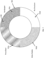
FIG. 2 is a front elevational view of a sidewall molding surface of a tire mold, illustrating four distinct exemplary negative irregular rough surface texture patterns, in accordance with the present disclosure; -
FIG. 3 is a fragmentary, enlarged perspective view of the sidewall molding surface ofFIG. 2 , illustrating the negative sidewall lettering pattern, in accordance with the present disclosure; -
FIG. 4 is a cross-sectional view of the sidewall molding surface ofFIG. 2 , illustrating raised and recessed portions of a pebble pattern, in accordance with the present disclosure; -
FIG. 5 is a cross-sectional view of the sidewall molding surface ofFIG. 2 , illustrating raised and recessed portions of an inverse pebble pattern, in accordance with the present disclosure; -
FIG. 6 is a cross-sectional view of the sidewall molding surface ofFIG. 2 , illustrating raised and recessed portions of a rough sandpaper pattern, in accordance with the present disclosure; -
FIG. 7 is a front elevational view of yet another sidewall molding surface of a tire mold, illustrating yet another set of four distinct exemplary negative irregular rough surface texture patterns, in accordance with the present disclosure; -
FIG. 8 is a cross-sectional, expanded view of a three-piece tire mold, illustrating cross-sections of a pair of sidewall rings and a tread molding portion, in accordance with the present disclosure; -
FIG. 9 is a cross-sectional, assembled view of the three-piece tire mold ofFIG. 8 , illustrating cross-sections of the pair of sidewall rings and the tread molding portion assembled together to create a tire molding cavity, in accordance with the present disclosure; -
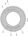
FIG. 10 is a side elevational view of a pneumatic tire with an irregular rough surface sandpaper texture finish extending circumferentially along the annular exterior surface of the tire sidewall, in accordance with the present disclosure; and -
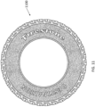
FIG. 11 is side elevational view of a pneumatic tire with an irregular rough surface pebble texture finish extending circumferentially along the annular exterior surface of the tire sidewall, in accordance with the present disclosure. - While the specification concludes with claims defining the features of the disclosure that are regarded as novel, it is believed that the disclosure will be better understood from a consideration of the following description in conjunction with the drawing figures, in which like reference numerals are carried forward. It is to be understood that the disclosed embodiments are merely exemplary and can be embodied in various forms.
- The present disclosure provides a novel and efficient tire mold, pneumatic tire, and method of producing the same with an irregular rough surface texture finish on the annular exterior surfaces of the tire that provides a unique textured visual appearance. Embodiments include irregular rough surface texture finishes with recessed portions non-uniformly disposed between irregular raised portions on a tire sidewall. In addition, embodiments of include the recessed portions having an irregularity depth of between 0.1 millimeters and 0.5 millimeters. As used herein, the term "between" and the ranges recited herein are intended to be inclusive of the outer limits defining the range (e.g., inclusive of 0.1 millimeters and 0.5 millimeters). In one embodiment, the rough surface texture finish may resemble rough sandpaper and, in an alternative embodiment, the rough surface texture finish may resemble a non-uniformly spaced apart pebble arrangement.
- Referring now to
FIG. 1 , one embodiment is shown in a perspective view.FIG. 1 shows several advantageous features of the present disclosure, but, as will be described below, the embodiments can be provided in several shapes, sizes, combinations of features and components, and varying numbers and functions of the components. The first example of atire molding surface 100 with a negative irregular roughsurface texture pattern 102, as shown inFIG. 1 , is provided in the form of asidewall ring plate 104. - As will be discussed herein below, with reference to
FIGS. 8 and 9 , atire mold 900 used in accordance with the present disclosure may be a three-piece tire mold with a pair ofsidewall ring plates FIG. 9 ). The sidewall molding surfaces in accordance with the present disclosure will be discussed with reference to the annular surface of thesidewall ring plate 104; however, it should be understood that some alternative embodiments may provide for sidewall molding surfaces in other types of tire molds, such as a one-piece tire mold in which the sidewall molding surfaces and the tread molding surfaces are integral with one another. - As can be seen in
FIG. 1 , in a preferred embodiment, the negative irregular roughsurface texture pattern 102 extends circumferentially along substantially the entiresidewall molding surface 100, except for the portions of the sidewall molding surface with lettering-numbering and/or logos. Stated another way, the negative irregular roughsurface texture pattern 102 may extend circumferentially continuously 360 degrees along thesidewall molding surface 100. Accordingly, as a result of agreen tire 800 being cured in the tire mold 900 (seeFIG. 9 ), anannular exterior surface 1000 of atire sidewall 1002 is provided with an irregular roughsurface texture finish 1004 that extends continuously circumferentially along the tire sidewall 1002 (seeFIG. 10 ). As should be apparent to those of ordinary skill in the art, thenegative pattern 102 on thesidewall molding surface 100 should be a mirror image of the resulting pattern on the curedtire sidewall 1002. - In another embodiment, the negative irregular rough
surface texture pattern 102 may extend circumferentially less than 360 degrees along thesidewall molding surface 100, such as, for example 270 degrees, 180 degrees, or 90 degrees along thesidewall molding surface 100. As should be apparent to those of ordinary skill in the art, thenegative pattern 102 on thesidewall molding surface 100 should be a mirror image of the resulting pattern on the curedtire sidewall 1002. - In yet other embodiments, the negative irregular rough
surface texture pattern 102 may extend discontinuously, circumferentially along thesidewall molding surface 100. In other words, the negative irregular roughsurface texture pattern 102 may have intervals or gaps between sub-sections of the negative irregular rough surface texture. The intervals or gaps may be formed as smooth surfaces to contrast with the irregular rough surface texture sub-sections. Alternatively, the intervals or gaps between sub-sections of the negative irregular rough surface texture may be formed as a different/alternating negative irregular rough surface texture sub-sections. In a further embodiment, the negative irregular rough surface texture sub-sections may be equally spaced apart from one another. As should be apparent to those of ordinary skill in the art, a discontinuous,negative pattern 102 on thesidewall molding surface 100 should be a mirror image of the resulting pattern on the curedtire sidewall 1002. - Referring now primarily to
FIG. 2 , a sidewall ring plate 200 (similar to thesidewall ring plate 104 depicted inFIG. 1 ) is shown in a front elevational view with multiple negative irregular roughsurface texture patterns sidewall molding surface 100 with a single irregular roughsurface texture pattern 102 extending circumferentially along themolding surface 100, as illustrated inFIG. 1 ; for illustrative purposes thesidewall ring plate 200 shown inFIG. 2 includes fourpatterns molding surface 100 for purposes of describing the various rough surface patterns that may be provided in accordance with various embodiments of the present disclosure. - In the exemplary embodiment, the negative irregular rough
surface texture pattern 102 defined on thesidewall molding surface 100 may be considered apebble pattern 102a. Stated another way, the negative irregular roughsurface texture pattern 102 may be configured to mold a pebble pattern on theannular exterior surface 1000 of thetire sidewall 1002. - Referring now specifically to
FIG. 4 , with reference still toFIG. 2 , the negative irregular rough surface texture pattern 102 (shown inFIG. 4 as a cross-section of thepebble pattern 102a) may define recessedportions 400 disposed non-uniformly between raisedportions 402. The raisedportions 402 may be the irregular-shaped pebble portions of thepattern 102a and the recessedportions 400 may be the irregular-shaped spaces between pebble portions of thepattern 102a. The pebble portions may be considered generally circular or oval in overall shape, yet follow an irregular curve-shaped path/outline, similar to the irregular-shape of pebbles, hence the name "pebble pattern." The spaces between the pebble portions may be non-linear and non-uniform in dimension in some embodiments (as shown inFIG. 4 ). - The recessed
portions 400 and the raisedportions 402 may be considered to vary non-uniformly in size and shape, one from another, along thesidewall molding surface 100. Stated another way, the dimensions of the recessedportions 400 and the dimensions of the raisedportions 402 may vary randomly along thesidewall molding surface 100. In particular,FIG. 4 shows an embodiment in which the widths of the recessedportions 400, Wa(recess) - Wn(recess), vary non-uniformly one from the other. Similarly,FIG. 4 shows an embodiment in which the widths of the raisedportions 402, Wa(raised) - Wn(raised), vary non-uniformly one from the other. The number of raisedportions 402 and the number of recessedportions 400 may be any number from a to n. - In one embodiment, the raised
portions 402 may have a maximum width, Wa(raised), or diameter that is 1.5 millimeters. In another embodiment, the raisedportions 402 may have a maximum width, Wa(raised), that is 1 millimeter. In yet another embodiment, the raisedportions 402 may have a maximum width, Wa(raised), that is 2.5 millimeters. In yet other embodiments, the raisedportions 402 may have a maximum width, Wa(raised), that is outside of those ranges. - In some embodiments, a width and a depth of the recessed
portions 400 may be the same across thepattern 102, yet the path and shape of the recessedportions 400 may still be irregular and follow a non-uniform path across thepattern 102. This may be the case, for example, in embodiments in which a laser beam may be used to etch an irregular pattern on a generally planar steel plate. The laser beam may create recessedportions 400 that have substantially the same width and depth (corresponding to the strength and size of the laser beam); however, the path that the laser beam follows should be irregular or non-uniform to create an irregular, non-uniform rough surface texture on themolding surface 100. - Similarly, a height of the raised
portions 402 may, in some embodiments, be the same across thepattern 102, yet the shape and/or width of the raisedportions 402 may be irregular and non-uniform across thepattern 102. In other words, the shape of one raisedportion 402 may be different from the shape of its neighboring raisedportion 402, as with actual pebbles (see for exampleFIG. 2 pebble) - The recessed
portions 400 and raisedportions 402 should be provided with dimensions that create an irregular roughsurface texture finish 1004 on the tire sidewall 1002 (seeFIGS. 10 and11 ) that is visually discernable by an outside observer. In other words, the irregular rough surface texture finish 1004 (whether it resembles sandpaper or a pebble pattern) should be visually discernible as compared to the other exterior surfaces of the tire. Stated yet another way, the irregular roughsurface texture finish 1004 should be configured as an apparent tire sidewall pattern that was intentionally created to provide a unique visual effect on thetire sidewall 1002, as opposed to mere random surface defect irregularities that may only be visible by a very close-up tire inspection. - In one embodiment, the negative irregular rough
surface texture pattern 102 may be provided with dimensions to create an irregular roughsurface texture finish 1004 on the tire sidewall 1002 (seeFIGS. 10 and11 ) that is visually discernible by an observer from at least 5 feet away from thetire sidewall 1002. In yet another embodiment, the irregular roughsurface texture finish 1004 may be configured to be visually discernible by an observer from at least 10 feet away from thetire sidewall 1002. Importantly, the irregular roughsurface texture finish 1004 should provide a unique look and feel to thetire sidewall 1002, which departs from the conventional glossy sidewall appearance that is sought after, or the uniform regular tire sidewall patterns existing in the art today. - In one embodiment, the recessed
portions 400 have adepth 404 of at least 0.1 millimeters. In another embodiment, the recessedportions 400 may have adepth 404 that is 0.3 millimeters. In yet another embodiment, the recessedportions 400 may have adepth 404 that is 0.5 millimeters. In yet another embodiment, the recessedportions 400 may have adepth 404 of between 0.1 to 0.5 millimeters. Thedepth 404 of the recessedportions 400 may also be referred to as an irregularity depth. - A
height 406 of the raisedportions 402 may correspond to thedepth 404 of the recessedportions 400. For example, in an embodiment where a smooth/planar sidewall molding surface is laser etched with an irregular rough surface texture pattern to create the rough textured,sidewall ring plate 104, the laser beam may create the recessedportions 400, which thereby define the raisedportions 400. In other words, the raisedportions 400 may be considered the remaining surfaces of the planar sidewall molding surfaces that were not cut/etched by the laser beam. Accordingly, in some embodiments, the raisedportions 402 may have aheight 406 of at least 1 millimeter. In another embodiment, the raisedportions 402 may have aheight 406 that is 0.3 millimeters. In yet another embodiment, the raisedportions 402 may have aheight 406 that is 0.5 millimeters. In yet another embodiment, the raisedportions 402 may have aheight 406 of between 0.1 to 0.5 millimeters. - The amount and dimensions of the raised
portions 402 and the amount and dimensions of the recessedportions 400 should preferably be selected to be sufficiently substantial to be visually discernible by an outside observer, but also not too large to be susceptible to cracks in the tire sidewall. For example, while agreater depth 404 of the recessedportions 400 and agreater height 406 of the raisedportions 402 may be more visually discernible to an outside observer for some patterns, if the recessedportions 400 are too deep over time the tire sidewall may be at an unacceptable risk of forming cracks too early in the tire life cycle. - Although the description thus far has been primarily focused on describing the negative irregular rough
surface texture pattern 102, with reference to thepebble pattern 102a depicted inFIGS. 2 and4 , it should be understood that other embodiments may provide other types of irregular roughsurface texture patterns portions 402 and the recessedportions 400 and other arrangements and configurations of the negative irregular roughsurface texture pattern 102 apply also with respective to suchalternative patterns - Referring now again to
FIG. 2 , thesidewall ring plate 200 illustrates various alternative negative irregular roughsurface texture patterns 102a-d. Thepattern 102b may be considered an inversepebble pattern 102b.FIG. 5 illustrates a close-up view of a portion of the inversepebble pattern 102b. With the inversepebble pattern 102b, the recessedportions 500 and the raisedportions 502 are the inverse of thepebble pattern 102a. Specifically, the raisedportions 502 correspond to the irregular-shaped spaces between the pebble portions and the recessedportions 500 correspond to the irregular-shaped pebble portions. As described herein above, the irregular-shaped pebble portions are considered generally circular or oval in overall shape, yet follow an irregular curve-shaped path/outline, similar to the irregular-shape of pebbles, hence the name "pebble pattern." The description herein above with respect to the dimensions and arrangement of thepebble pattern 102a apply also to the inversepebble pattern 102b and therefore will not be expressly repeated. - Referring again to
FIG. 2 , with reference also toFIGS. 3 and6 , thepattern 102c may be considered arough sandpaper pattern 102c. As with thepebble patterns rough sandpaper pattern 102c may include recessedportions 600 disposed non-uniformly between raisedportions 602 in a manner that resembles a sandpaper surface. In a preferred embodiment, the recessedportions 600 may have adepth 604 of 0.1 millimeters. In a further embodiment, thesidewall molding surface 100 may be created by laser etching a smooth sidewall ring plate with cuts 0.1 millimeters deep. In other embodiments, thedepth 604 may be slightly greater or less than 0.1 millimeters. In yet other embodiments, thedepth 604 of the recessedportions 600 may be in the range of 0.1 millimeters to 0.3 millimeters. In yet further embodiments, thedepth 604 of the recessedportions 600 may be in the range of 0.1 to 0.5 millimeters. Importantly, the cuts or depth of the recessedportions 600 and the overall arrangement of recessedportions 600 and raisedportions 602 should appear intentionally coarse, in other words, resembling rough sandpaper.FIG. 3 is a close-up view of thesandpaper patterns sidewall molding surface 100. - As with real sandpaper, the texture of the
sandpaper pattern portions 602, is proportional to the coarseness of the sandpaper surface. Thepattern 102d may be considered asmooth sandpaper pattern 102d, as compared to therough sandpaper pattern 102c. - Referring now primarily to
FIG. 3 , with reference toFIG. 10 , thesidewall molding surface 100 may also define anegative indicia pattern 300 overlaying the negative irregular roughsurface texture patterns negative indicia pattern 300 may include a negative space in the mold for creating sidewall lettering, manufacturer names, tire model information, and the like, and may include letters, numbers, as well, as other symbols, such as logos. In one embodiment, thenegative indicia pattern 300 may include anindicia depth 302 that is greater than the depth of the recessedportions 600 so as to mold theannular exterior surface 1000 of thetire sidewall 1002 with sidewall indicia 1006 (seeFIG. 10 ). The sidewall indicia 1006 preferably protrudes outwardly extending beyond the irregular roughsurface texture finish 1004 created by themold texture pattern 102. In other words, thesidewall indicia 1006 preferably overlays the irregular roughsurface texture finish 1004. - Referring now primarily to
FIG. 7 , yet another exemplary sidewall ring plate 700 (similar to thesidewall ring plate 104 depicted inFIG. 1 and thesidewall ring plate 200 depicted inFIG. 2 ) is shown in a front elevational view with multiple negative irregular roughsurface texture patterns surface texture pattern 702a may be considered a pinch or burl effect pattern, with raised and protruding portions arranged to resemble a pinch or burl effect, as depicted inFIG. 7 . The negative irregular roughsurface texture pattern 702b may be considered a wide pebble pattern, with protruding portions more widely spaced apart than the otherpebble patterns FIGS. 2 ,4, and 5 ). The negative irregular roughsurface texture pattern 702c may be considered yet another sandpaper pattern with a different coarseness, as compared to theother sandpaper patterns FIGS. 2 and6 ). Thefinish 702d may be considered a no structure, prior art pattern, having, for example, a smooth or a polished finish on thesidewall molding surface 100, shown as a comparison of embodiments of the present disclosure to existing mold surfaces. - Referring now primarily to
FIGS. 8 and 9 , a cross-sectional view of thetire mold 900 is shown as a three-piece mold with the pair ofsidewall ring plates tread molding portion 902. The general construction of tire molds is known by those of ordinary skill in the art and therefore will not be described in great detail. In the exemplary embodiment, the negative irregular roughsurface texture pattern 102 is provided on the sidewall molding surfaces 100 of thesidewall ring plates surface texture pattern 102 may extend circumferentially along each of thesidewall ring plates - As is generally known, the
tread molding portion 902 may include a negative tread pattern. In a further embodiment, there may also be provided a negative irregular roughsurface texture pattern 102 on thetread molding portion 902 to provide a unique visual effect on theannular exterior surface 1000 of thetire tread 1010, as well. In one embodiment, the irregular rough surface texture of thetire tread 1010 may be configured to resemble the irregular roughsurface texture finish 1004 of thetire sidewall 1002. In other embodiments, thetread molding portion 902 may not include a negative irregular roughsurface texture pattern 102. Because tire sidewalls are more visually prominent than thetire tread 1010 when installed on a vehicle, embodiments may only provide the irregular roughsurface texture finish 1004 on thetire sidewall 1002, rather than thetire tread 1010. - During the manufacturing process, the
green tire 800 may be placed within thetire mold cavity 904 defined by the tread and sidewall molding surfaces of thetire mold 900, as is generally known. After curing thegreen tire 800, apneumatic tire 1008 is formed with the irregular roughsurface texture finish 1004 on the tire sidewall 1002 (seeFIG. 10 ), the irregular roughsurface texture finish 1004 being a mirror image of the negative irregular roughsurface texture pattern 102 on the sidewall ring plate 104 (seeFIGS. 1 and2 ). - As is generally known, a tire includes a pair of tire sidewalls axially spaced apart from one another and extending from respective opposite ends of the
tire tread 1010. Accordingly, although not shown, it should be apparent that the opposite tire sidewall (not shown inFIG. 10 ) also includes the irregular roughsurface texture finish 1004. -
FIG. 10 illustrates thepneumatic tire 1008 made with a sidewall molding surface having therough sandpaper pattern 102c thereon, in accordance with the present disclosure.FIG. 11 illustrates another exemplarypneumatic tire 1100 made with a sidewall molding surface having thepebble pattern 102a thereon, in accordance with the present disclosure. - By providing the
tire mold 900 with negative irregular roughsurface texture patterns 102, 702, the irregular roughsurface texture finish 1004 may be formed integrally with thetire sidewall 1002, rather than, for example, being molded onto the tire, after thegreen tire 800 is cured, as a separate manufacturing process. Doing so reduces the time, cost, and complexity of the manufacturing process, as compared with, for example, a process with a separate post-curing step. - A novel and efficient tire mold, pneumatic tire, and method of producing the same has been disclosed to provide an irregular rough surface texture finish on the annular exterior surface of the tire that provides a unique textured visual appearance. Embodiments provide irregular rough surface texture finishes with recessed portions non-uniformly disposed between irregular raised portions on a tire sidewall. In one embodiment, the rough surface texture finish may resemble rough sandpaper and, in an alternative embodiment, the rough surface texture finish may resemble a non-uniformly spaced apart pebble arrangement.
- Additionally, the following examples are provided.
- 1. An apparatus comprising:
- a tire mold having a sidewall molding surface with a negative irregular rough surface texture pattern extending circumferentially along the sidewall molding surface so as to mold at least one annular exterior surface of a tire sidewall with an irregular rough surface texture, the negative irregular rough surface texture pattern defining recessed portions disposed non-uniformly between raised portions, the recessed portions having a depth of at least 0.1 millimeters.
- 2. The apparatus in accordance with example 1, wherein:
the recessed portions and the raised portions vary non-uniformly in size and shape along the sidewall molding surface. - 3. The apparatus in accordance with example 1, wherein:
the recessed portions have a depth of 0.1 - 0.5 millimeters. - 4. The apparatus in accordance with example 1, wherein:
the recessed portions have a depth of 0.3 millimeters. - 5. The apparatus in accordance with example 1, wherein:
the sidewall molding surface is a surface of a sidewall ring plate. - 6. The apparatus in accordance with example 1, wherein:
the negative irregular rough surface texture pattern is configured to mold a rough sandpaper pattern on the at least one annular exterior surface of the tire sidewall, the rough sandpaper pattern being visually discernible from other exterior surfaces of the tire by an observer. - 7. The apparatus in accordance with example 1, wherein:
the negative irregular rough surface texture pattern is configured to mold a pebble pattern on the at least one annular exterior surface of the tire sidewall, the pebble pattern being visually discernible from other exterior surfaces of the tire by an observer. - 8. The apparatus in accordance with example 1, wherein:
the sidewall molding surface defines a negative indicia pattern with an indicia depth that is greater than the depth of the recessed portions so as to mold the at least one annular exterior surface of the tire sidewall with the indicia pattern overlaying the irregular rough surface texture. - 9. The apparatus in accordance with example 1, wherein:
the negative irregular rough surface texture pattern is formed by laser etching a planar sidewall molding surface in a non-uniform laser pattern to create the recessed portions, said laser-etched recessed portions thereby defining the raised portions, the raised portions being portions of the planar sidewall molding surface not laser etched. - 10. The apparatus in accordance with example 1, wherein:
the tire mold includes a tread molding surface, the tread molding surface with a negative irregular rough surface texture pattern corresponding to the negative irregular rough surface texture pattern on the sidewall molding surface so as to mold at least one annular exterior surface of a tire tread with an irregular rough surface texture corresponding to the irregular rough surface texture of the tire sidewall. - 11. The apparatus in accordance with example 1, wherein:
the negative irregular rough surface texture pattern extends circumferentially continuously 360 degrees along the sidewall molding surface. - 12. An apparatus comprising:
a tire mold having a sidewall molding surface with a negative irregular rough surface texture pattern extending circumferentially along the sidewall molding surface so as to mold at least one annular exterior surface of a tire sidewall with an irregular rough surface texture, the negative irregular rough surface texture pattern having an irregularity depth of at least 0.1 millimeters. - 13. The apparatus in accordance with example 12, wherein:
the irregularity depth is in a range of 0.1 - 0.5 millimeters. - 14. The apparatus in accordance with example 12, wherein:
the irregularity depth is 0.3 millimeters. - 15. The apparatus in accordance with example 12, wherein:
the sidewall molding surface is a surface of a sidewall ring plate. - 16. The apparatus in accordance with example 12, wherein:
the negative irregular rough surface texture pattern is configured to mold one of a rough sandpaper pattern, and a pebble pattern on the at least one annular exterior surface of the tire sidewall, the one of the rough sandpaper pattern, and the pebble pattern being visually discernible from other exterior surfaces of the tire by an observer. - 17. A pneumatic tire comprising:
- a first and a second sidewall each axially spaced apart from one another and extending from respective opposite ends of a tread; and
- at least one of the first and second sidewalls having an annular exterior surface with an irregular rough surface texture, the irregular rough surface texture:
- having an irregularity depth of at least 0.1 millimeters,
- being integrally formed on the annular exterior surface, and
- formed so as to provide a non-uniform, coarse surface texture finish that extends circumferentially along the annular exterior surface of the at least one of the first and second sidewalls.
- 18. The pneumatic tire in accordance with example 17, wherein:
the irregularity depth is in a range of 0.1 - 0.5 millimeters. - 19. The apparatus in accordance with example 17, wherein:
the irregularity depth is 0.3 millimeters. - 20. The pneumatic tire in accordance with example 17, wherein:
- the irregular rough surface texture is one of a rough sandpaper pattern and a pebble pattern,
- the one of the rough sandpaper pattern and the pebble pattern being visually discernible from other exterior surfaces of the pneumatic tire by an observer
Claims (6)
- A pneumatic tire (1008) comprising:a first and a second sidewall (1002) each axially spaced apart from one another and extending from respective opposite ends of a tread (1010); andat least one of the first and second sidewalls (1002) having an annular exterior surface (1000) with an irregular rough surface texture (1004), the irregular rough surface texture (1004):defining recessed portions (400, 500, 600) disposed non-uniformly between raised portions (402, 502, 602), the recessed portions (400, 500, 600) having a depth having an irregularity depth (404, 604) of 0.1-0.5 millimeters,being integrally formed on the annular exterior surface (1000), andformed so as to provide a non-uniform, coarse surface texture finish that extends continuously circumferentially along the annular exterior surface (1000) of the at least one of the first and second sidewalls (1002).
- The pneumatic tire (1008) in accordance with claim 1, wherein:the irregularity depth (404, 604) is 0.3 millimeters.
- The pneumatic tire (1008) in accordance with claim 1 or 2, wherein:the irregular rough surface texture (1004) is one of a rough sandpaper pattern (102c, 102d) and a pebble pattern (102a, 102b), the one of the rough sandpaper pattern (102c, 102d) andthe pebble pattern (102a, 102b) being visually discernible from other exterior surfaces of the pneumatic tire by an observer.
- The pneumatic tire (1008) in accordance with any of claims 1 to 3, wherein:
the recessed portions (400, 500, 600) and the raised portions (402, 502, 602) vary non-uniformly in size and shape along the annular exterior surface (1000). - The pneumatic tire (1008) in accordance with any of claims 1 to 4, wherein:
the recessed portions (400, 500, 600) and the raised portions (402, 502, 602) include dimensions that vary randomly along the annular exterior surface (1000). - The pneumatic tire (1008) in accordance with any of claims 1 to 5, wherein:
the recessed portions (400, 500, 600) are non-linear and nonuniform in dimension
Applications Claiming Priority (3)
| Application Number | Priority Date | Filing Date | Title |
|---|---|---|---|
| US201762561704P | 2017-09-22 | 2017-09-22 | |
| PCT/US2018/051900 WO2019060517A1 (en) | 2017-09-22 | 2018-09-20 | Pneumatic tire with a textured surface, method of manufacturing, and textured mold |
| EP18858222.5A EP3684606B1 (en) | 2017-09-22 | 2018-09-20 | Mold for manufacturing pneumatic tire with a textured surface |
Related Parent Applications (2)
| Application Number | Title | Priority Date | Filing Date |
|---|---|---|---|
| EP18858222.5A Division EP3684606B1 (en) | 2017-09-22 | 2018-09-20 | Mold for manufacturing pneumatic tire with a textured surface |
| EP18858222.5A Division-Into EP3684606B1 (en) | 2017-09-22 | 2018-09-20 | Mold for manufacturing pneumatic tire with a textured surface |
Publications (2)
| Publication Number | Publication Date |
|---|---|
| EP4212363A1 true EP4212363A1 (en) | 2023-07-19 |
| EP4212363B1 EP4212363B1 (en) | 2025-06-18 |
Family
ID=65810923
Family Applications (2)
| Application Number | Title | Priority Date | Filing Date |
|---|---|---|---|
| EP23160356.4A Active EP4212363B1 (en) | 2017-09-22 | 2018-09-20 | Pneumatic tire with a textured surface |
| EP18858222.5A Active EP3684606B1 (en) | 2017-09-22 | 2018-09-20 | Mold for manufacturing pneumatic tire with a textured surface |
Family Applications After (1)
| Application Number | Title | Priority Date | Filing Date |
|---|---|---|---|
| EP18858222.5A Active EP3684606B1 (en) | 2017-09-22 | 2018-09-20 | Mold for manufacturing pneumatic tire with a textured surface |
Country Status (3)
| Country | Link |
|---|---|
| US (2) | US12122192B2 (en) |
| EP (2) | EP4212363B1 (en) |
| WO (1) | WO2019060517A1 (en) |
Families Citing this family (3)
| Publication number | Priority date | Publication date | Assignee | Title |
|---|---|---|---|---|
| USD1001726S1 (en) * | 2021-04-19 | 2023-10-17 | Continental Reifen Deustschland Gmbh | Sidewall of a tire with graphic symbol |
| EP4538067A1 (en) * | 2023-10-12 | 2025-04-16 | The Goodyear Tire & Rubber Company | Tire or item having a contrasting surface and method for creating contrast on a surface |
| DE102024200699A1 (en) * | 2024-01-26 | 2025-07-31 | Continental Reifen Deutschland Gmbh | Vulcanization mold for a two-wheel tire and insert for insertion into a sidewall shell of a vulcanization mold for a two-wheel tire |
Citations (5)
| Publication number | Priority date | Publication date | Assignee | Title |
|---|---|---|---|---|
| JP2003252012A (en) * | 2002-03-04 | 2003-09-09 | Sumitomo Rubber Ind Ltd | Pneumatic tire |
| DE102012104890A1 (en) * | 2012-06-05 | 2013-12-05 | Continental Reifen Deutschland Gmbh | Polymer product, preferably vehicle tires |
| US20140378030A1 (en) * | 2010-03-26 | 2014-12-25 | Bridgestone Corporation | Pneumatic tire and method of manufacturing tire vulcanization mold |
| FR3022851A1 (en) * | 2014-06-30 | 2016-01-01 | Michelin & Cie | PNEUMATIC COMPRISING A HIGH CONTRAST MARKING |
| US20170080759A1 (en) * | 2013-07-01 | 2017-03-23 | Bridgestone Americas Tire Operations, Llc | Methods and apparatuses for creating a visual effect on a rubber article |
Family Cites Families (24)
| Publication number | Priority date | Publication date | Assignee | Title |
|---|---|---|---|---|
| US4823856A (en) | 1984-12-19 | 1989-04-25 | The Goodyear Tire & Rubber Company | Serrated outline marking for a tire side wall |
| JPS6416408A (en) * | 1987-07-10 | 1989-01-19 | Yokohama Rubber Co Ltd | Pneumatic tyre and molding tool for the tyre |
| AT397373B (en) | 1990-05-14 | 1994-03-25 | Semperit Ag | VEHICLE TIRES |
| FR2677303A1 (en) | 1991-06-10 | 1992-12-11 | Michelin & Cie | Head and device for marking the walls of tyres and a method for implementing them |
| CA2180770A1 (en) | 1996-03-11 | 1997-09-12 | Bill Joe Ratliff, Jr. | Tire sidewall mosaic design patterns |
| JPH11321243A (en) * | 1998-05-18 | 1999-11-24 | Bridgestone Corp | Pneumatic tire provided with an annular decorative body composed of a large number of hemispherical projections |
| US6536490B2 (en) | 2001-06-15 | 2003-03-25 | The Goodyear Tire & Rubber Company | Off-road tire having a textured inner tread |
| US7156936B2 (en) | 2003-07-01 | 2007-01-02 | The Goodyear Tire & Rubber Company | Camouflage or otherwise multicolored pattern tire and method of manufacturing |
| US7387144B2 (en) | 2005-02-25 | 2008-06-17 | Bridgestone Firestone North American Tire, Llc | Tire having a textured marking and method of making same |
| US7409975B2 (en) | 2005-05-13 | 2008-08-12 | Bridgestone Firestone North American Tire, Llc | Apparatus for enhancing light reflective properties of tire sidewalls |
| KR20070042679A (en) * | 2005-10-19 | 2007-04-24 | 금호타이어 주식회사 | Sidewalls of Car Tires |
| RU2523881C2 (en) * | 2009-06-12 | 2014-07-27 | Сумитомо Раббер Индастриз, Лтд. | Transport facility |
| JP4920760B2 (en) * | 2010-04-08 | 2012-04-18 | 東洋ゴム工業株式会社 | Pneumatic tire, tire mold, and method for manufacturing pneumatic tire |
| JP5039810B2 (en) * | 2010-05-18 | 2012-10-03 | 東洋ゴム工業株式会社 | Tire mold and method for manufacturing pneumatic tire |
| JP6088137B2 (en) * | 2011-12-28 | 2017-03-01 | 株式会社ブリヂストン | Tire and tire mold |
| FR3007324B1 (en) | 2013-06-20 | 2015-07-17 | Michelin & Cie | PNEUMATIC COMPRISING A HIGH CONTRAST MARKING |
| USD695212S1 (en) | 2013-07-01 | 2013-12-10 | Bridgestone Americas Tire Operations, Llc | Tire sidewall |
| FR3009228B1 (en) * | 2013-08-05 | 2015-08-21 | Michelin & Cie | PNEUMATIC MOLD COMPRISING AN ANNULAR INSERT IN SEVERAL PARTS |
| FR3009231B1 (en) * | 2013-08-05 | 2016-01-01 | Michelin & Cie | PNEUMATIC MOLD COMPRISING A SHELL WITH REMOVABLE PARTS |
| FR3009522B1 (en) | 2013-08-07 | 2016-12-23 | Michelin & Cie | PNEUMATIC COMPRISING ON A FLANK A PARTICULAR TEXTURE |
| USD750015S1 (en) | 2013-11-18 | 2016-02-23 | Bridgestone Americas Tire Operations, Llc | Tire sidewall |
| USD750553S1 (en) | 2013-11-18 | 2016-03-01 | Bridgestone Americas Tire Operations, Llc | Tire sidewall |
| FR3020594B1 (en) | 2014-04-30 | 2018-01-05 | Compagnie Generale Des Etablissements Michelin | PNEUMATIC COMPRISING A MATRIX SYMBOL WITH HIGH CONTRAST ON THE FLANK |
| WO2016106190A1 (en) * | 2014-12-22 | 2016-06-30 | Bridgestone Americas Tire Operations, Llc | Tire mold and vent insert having corresponding surfaces |
-
2018
- 2018-09-20 EP EP23160356.4A patent/EP4212363B1/en active Active
- 2018-09-20 WO PCT/US2018/051900 patent/WO2019060517A1/en not_active Ceased
- 2018-09-20 US US16/642,034 patent/US12122192B2/en active Active
- 2018-09-20 EP EP18858222.5A patent/EP3684606B1/en active Active
-
2024
- 2024-09-13 US US18/885,143 patent/US12479178B2/en active Active
Patent Citations (5)
| Publication number | Priority date | Publication date | Assignee | Title |
|---|---|---|---|---|
| JP2003252012A (en) * | 2002-03-04 | 2003-09-09 | Sumitomo Rubber Ind Ltd | Pneumatic tire |
| US20140378030A1 (en) * | 2010-03-26 | 2014-12-25 | Bridgestone Corporation | Pneumatic tire and method of manufacturing tire vulcanization mold |
| DE102012104890A1 (en) * | 2012-06-05 | 2013-12-05 | Continental Reifen Deutschland Gmbh | Polymer product, preferably vehicle tires |
| US20170080759A1 (en) * | 2013-07-01 | 2017-03-23 | Bridgestone Americas Tire Operations, Llc | Methods and apparatuses for creating a visual effect on a rubber article |
| FR3022851A1 (en) * | 2014-06-30 | 2016-01-01 | Michelin & Cie | PNEUMATIC COMPRISING A HIGH CONTRAST MARKING |
Also Published As
| Publication number | Publication date |
|---|---|
| WO2019060517A1 (en) | 2019-03-28 |
| US20200247077A1 (en) | 2020-08-06 |
| US20250010666A1 (en) | 2025-01-09 |
| EP4212363B1 (en) | 2025-06-18 |
| US12479178B2 (en) | 2025-11-25 |
| US12122192B2 (en) | 2024-10-22 |
| EP3684606A4 (en) | 2021-05-19 |
| EP3684606A1 (en) | 2020-07-29 |
| EP3684606B1 (en) | 2023-04-12 |
Similar Documents
| Publication | Publication Date | Title |
|---|---|---|
| US12479178B2 (en) | Pneumatic tire with a textured surface, method of manufacturing, and textured mold | |
| EP3613614B1 (en) | Tire | |
| JP7204655B2 (en) | Tire with textured sidewalls | |
| JP5356447B2 (en) | Tire mold, method for producing pneumatic tire, and pneumatic tire | |
| US7021914B2 (en) | Tire mold | |
| JP3667818B2 (en) | Pneumatic tire with a decorative body consisting of many ridges | |
| CN106470827B (en) | Mold elements including high-contrast textured sections | |
| JP6699727B2 (en) | Pneumatic tire manufacturing method, tire mold, and pneumatic tire | |
| CN113891812A (en) | Pneumatic tire for vehicle | |
| US20110285064A1 (en) | Tire mold and manufacturing method of pneumatic tire | |
| CN109774385B (en) | Pneumatic tire | |
| JP2013252713A (en) | Tire mold, method of manufacturing pneumatic tire, and pneumatic tire | |
| CN110770046B (en) | Vehicle tyre | |
| WO2004002707A1 (en) | Method of manufacturing laminated mold and laminated mold | |
| US20140205695A1 (en) | Reinforced Thin Gage Tire Curing Bladder Mold Core | |
| JPH05177742A (en) | Split mold for retreaded tire and method for manufacturing retreaded tire | |
| EP3983215B1 (en) | Insert for a mould for vulcanising tyres for vehicle wheels and process for producing said insert | |
| CN114555346B (en) | Tire curing mold with removable insert and associated manufacturing method | |
| WO2025083559A1 (en) | Method for producing a vulcanization mold for a tyre for vehicle wheels | |
| JP2004255620A (en) | Tire mold and method for manufacturing pneumatic tire using the same | |
| BR112021024610B1 (en) | INSERT FOR A MOLD AND MOLD FOR VULCANIZING TIRES FOR VEHICLE WHEELS, AND PROCESS FOR PRODUCING AN INSERT | |
| JPH07156155A (en) | Tire forming mold and tire forming method | |
| JP2006142562A (en) | Laminated mold and its manufacturing method |
Legal Events
| Date | Code | Title | Description |
|---|---|---|---|
| PUAI | Public reference made under article 153(3) epc to a published international application that has entered the european phase |
Free format text: ORIGINAL CODE: 0009012 |
|
| STAA | Information on the status of an ep patent application or granted ep patent |
Free format text: STATUS: THE APPLICATION HAS BEEN PUBLISHED |
|
| AC | Divisional application: reference to earlier application |
Ref document number: 3684606 Country of ref document: EP Kind code of ref document: P |
|
| AK | Designated contracting states |
Kind code of ref document: A1 Designated state(s): AL AT BE BG CH CY CZ DE DK EE ES FI FR GB GR HR HU IE IS IT LI LT LU LV MC MK MT NL NO PL PT RO RS SE SI SK SM TR |
|
| STAA | Information on the status of an ep patent application or granted ep patent |
Free format text: STATUS: REQUEST FOR EXAMINATION WAS MADE |
|
| 17P | Request for examination filed |
Effective date: 20240118 |
|
| RBV | Designated contracting states (corrected) |
Designated state(s): AL AT BE BG CH CY CZ DE DK EE ES FI FR GB GR HR HU IE IS IT LI LT LU LV MC MK MT NL NO PL PT RO RS SE SI SK SM TR |
|
| GRAP | Despatch of communication of intention to grant a patent |
Free format text: ORIGINAL CODE: EPIDOSNIGR1 |
|
| STAA | Information on the status of an ep patent application or granted ep patent |
Free format text: STATUS: GRANT OF PATENT IS INTENDED |
|
| GRAJ | Information related to disapproval of communication of intention to grant by the applicant or resumption of examination proceedings by the epo deleted |
Free format text: ORIGINAL CODE: EPIDOSDIGR1 |
|
| STAA | Information on the status of an ep patent application or granted ep patent |
Free format text: STATUS: REQUEST FOR EXAMINATION WAS MADE |
|
| INTG | Intention to grant announced |
Effective date: 20250109 |
|
| STAA | Information on the status of an ep patent application or granted ep patent |
Free format text: STATUS: EXAMINATION IS IN PROGRESS |
|
| INTC | Intention to grant announced (deleted) | ||
| 17Q | First examination report despatched |
Effective date: 20250212 |
|
| GRAP | Despatch of communication of intention to grant a patent |
Free format text: ORIGINAL CODE: EPIDOSNIGR1 |
|
| STAA | Information on the status of an ep patent application or granted ep patent |
Free format text: STATUS: GRANT OF PATENT IS INTENDED |
|
| GRAS | Grant fee paid |
Free format text: ORIGINAL CODE: EPIDOSNIGR3 |
|
| GRAA | (expected) grant |
Free format text: ORIGINAL CODE: 0009210 |
|
| STAA | Information on the status of an ep patent application or granted ep patent |
Free format text: STATUS: THE PATENT HAS BEEN GRANTED |
|
| INTG | Intention to grant announced |
Effective date: 20250417 |
|
| P01 | Opt-out of the competence of the unified patent court (upc) registered |
Free format text: CASE NUMBER: APP_21072/2025 Effective date: 20250505 |
|
| AC | Divisional application: reference to earlier application |
Ref document number: 3684606 Country of ref document: EP Kind code of ref document: P |
|
| AK | Designated contracting states |
Kind code of ref document: B1 Designated state(s): AL AT BE BG CH CY CZ DE DK EE ES FI FR GB GR HR HU IE IS IT LI LT LU LV MC MK MT NL NO PL PT RO RS SE SI SK SM TR |
|
| REG | Reference to a national code |
Ref country code: GB Ref legal event code: FG4D |
|
| REG | Reference to a national code |
Ref country code: CH Ref legal event code: EP |
|
| REG | Reference to a national code |
Ref country code: DE Ref legal event code: R096 Ref document number: 602018082827 Country of ref document: DE |
|
| REG | Reference to a national code |
Ref country code: CH Ref legal event code: EP |
|
| REG | Reference to a national code |
Ref country code: IE Ref legal event code: FG4D |
|
| PG25 | Lapsed in a contracting state [announced via postgrant information from national office to epo] |
Ref country code: FI Free format text: LAPSE BECAUSE OF FAILURE TO SUBMIT A TRANSLATION OF THE DESCRIPTION OR TO PAY THE FEE WITHIN THE PRESCRIBED TIME-LIMIT Effective date: 20250618 |
|
| PGFP | Annual fee paid to national office [announced via postgrant information from national office to epo] |
Ref country code: DE Payment date: 20250820 Year of fee payment: 8 |
|
| REG | Reference to a national code |
Ref country code: LT Ref legal event code: MG9D |
|
| PG25 | Lapsed in a contracting state [announced via postgrant information from national office to epo] |
Ref country code: NO Free format text: LAPSE BECAUSE OF FAILURE TO SUBMIT A TRANSLATION OF THE DESCRIPTION OR TO PAY THE FEE WITHIN THE PRESCRIBED TIME-LIMIT Effective date: 20250918 Ref country code: GR Free format text: LAPSE BECAUSE OF FAILURE TO SUBMIT A TRANSLATION OF THE DESCRIPTION OR TO PAY THE FEE WITHIN THE PRESCRIBED TIME-LIMIT Effective date: 20250919 |
|
| PG25 | Lapsed in a contracting state [announced via postgrant information from national office to epo] |
Ref country code: BG Free format text: LAPSE BECAUSE OF FAILURE TO SUBMIT A TRANSLATION OF THE DESCRIPTION OR TO PAY THE FEE WITHIN THE PRESCRIBED TIME-LIMIT Effective date: 20250618 |
|
| PG25 | Lapsed in a contracting state [announced via postgrant information from national office to epo] |
Ref country code: HR Free format text: LAPSE BECAUSE OF FAILURE TO SUBMIT A TRANSLATION OF THE DESCRIPTION OR TO PAY THE FEE WITHIN THE PRESCRIBED TIME-LIMIT Effective date: 20250618 |
|
| PGFP | Annual fee paid to national office [announced via postgrant information from national office to epo] |
Ref country code: FR Payment date: 20250821 Year of fee payment: 8 |
|
| PG25 | Lapsed in a contracting state [announced via postgrant information from national office to epo] |
Ref country code: RS Free format text: LAPSE BECAUSE OF FAILURE TO SUBMIT A TRANSLATION OF THE DESCRIPTION OR TO PAY THE FEE WITHIN THE PRESCRIBED TIME-LIMIT Effective date: 20250918 |
|
| REG | Reference to a national code |
Ref country code: NL Ref legal event code: MP Effective date: 20250618 |
|
| PG25 | Lapsed in a contracting state [announced via postgrant information from national office to epo] |
Ref country code: LV Free format text: LAPSE BECAUSE OF FAILURE TO SUBMIT A TRANSLATION OF THE DESCRIPTION OR TO PAY THE FEE WITHIN THE PRESCRIBED TIME-LIMIT Effective date: 20250618 |
|
| PG25 | Lapsed in a contracting state [announced via postgrant information from national office to epo] |
Ref country code: NL Free format text: LAPSE BECAUSE OF FAILURE TO SUBMIT A TRANSLATION OF THE DESCRIPTION OR TO PAY THE FEE WITHIN THE PRESCRIBED TIME-LIMIT Effective date: 20250618 |
|
| PG25 | Lapsed in a contracting state [announced via postgrant information from national office to epo] |
Ref country code: PT Free format text: LAPSE BECAUSE OF FAILURE TO SUBMIT A TRANSLATION OF THE DESCRIPTION OR TO PAY THE FEE WITHIN THE PRESCRIBED TIME-LIMIT Effective date: 20251020 |
|
| REG | Reference to a national code |
Ref country code: AT Ref legal event code: MK05 Ref document number: 1803894 Country of ref document: AT Kind code of ref document: T Effective date: 20250618 |
|
| PG25 | Lapsed in a contracting state [announced via postgrant information from national office to epo] |
Ref country code: IS Free format text: LAPSE BECAUSE OF FAILURE TO SUBMIT A TRANSLATION OF THE DESCRIPTION OR TO PAY THE FEE WITHIN THE PRESCRIBED TIME-LIMIT Effective date: 20251018 |
|
| PG25 | Lapsed in a contracting state [announced via postgrant information from national office to epo] |
Ref country code: AT Free format text: LAPSE BECAUSE OF FAILURE TO SUBMIT A TRANSLATION OF THE DESCRIPTION OR TO PAY THE FEE WITHIN THE PRESCRIBED TIME-LIMIT Effective date: 20250618 Ref country code: SM Free format text: LAPSE BECAUSE OF FAILURE TO SUBMIT A TRANSLATION OF THE DESCRIPTION OR TO PAY THE FEE WITHIN THE PRESCRIBED TIME-LIMIT Effective date: 20250618 |
|
| PG25 | Lapsed in a contracting state [announced via postgrant information from national office to epo] |
Ref country code: CZ Free format text: LAPSE BECAUSE OF FAILURE TO SUBMIT A TRANSLATION OF THE DESCRIPTION OR TO PAY THE FEE WITHIN THE PRESCRIBED TIME-LIMIT Effective date: 20250618 |
|
| PG25 | Lapsed in a contracting state [announced via postgrant information from national office to epo] |
Ref country code: PL Free format text: LAPSE BECAUSE OF FAILURE TO SUBMIT A TRANSLATION OF THE DESCRIPTION OR TO PAY THE FEE WITHIN THE PRESCRIBED TIME-LIMIT Effective date: 20250618 |
|
| PG25 | Lapsed in a contracting state [announced via postgrant information from national office to epo] |
Ref country code: EE Free format text: LAPSE BECAUSE OF FAILURE TO SUBMIT A TRANSLATION OF THE DESCRIPTION OR TO PAY THE FEE WITHIN THE PRESCRIBED TIME-LIMIT Effective date: 20250618 |
|
| PG25 | Lapsed in a contracting state [announced via postgrant information from national office to epo] |
Ref country code: SK Free format text: LAPSE BECAUSE OF FAILURE TO SUBMIT A TRANSLATION OF THE DESCRIPTION OR TO PAY THE FEE WITHIN THE PRESCRIBED TIME-LIMIT Effective date: 20250618 |
|
| PG25 | Lapsed in a contracting state [announced via postgrant information from national office to epo] |
Ref country code: ES Free format text: LAPSE BECAUSE OF FAILURE TO SUBMIT A TRANSLATION OF THE DESCRIPTION OR TO PAY THE FEE WITHIN THE PRESCRIBED TIME-LIMIT Effective date: 20250618 |
|
| PG25 | Lapsed in a contracting state [announced via postgrant information from national office to epo] |
Ref country code: RO Free format text: LAPSE BECAUSE OF FAILURE TO SUBMIT A TRANSLATION OF THE DESCRIPTION OR TO PAY THE FEE WITHIN THE PRESCRIBED TIME-LIMIT Effective date: 20250618 |
|
| REG | Reference to a national code |
Ref country code: DE Ref legal event code: R097 Ref document number: 602018082827 Country of ref document: DE |
|
| PG25 | Lapsed in a contracting state [announced via postgrant information from national office to epo] |
Ref country code: DK Free format text: LAPSE BECAUSE OF FAILURE TO SUBMIT A TRANSLATION OF THE DESCRIPTION OR TO PAY THE FEE WITHIN THE PRESCRIBED TIME-LIMIT Effective date: 20250618 |
|
| PLBE | No opposition filed within time limit |
Free format text: ORIGINAL CODE: 0009261 |
|
| STAA | Information on the status of an ep patent application or granted ep patent |
Free format text: STATUS: NO OPPOSITION FILED WITHIN TIME LIMIT |
|
| REG | Reference to a national code |
Ref country code: CH Ref legal event code: L10 Free format text: ST27 STATUS EVENT CODE: U-0-0-L10-L00 (AS PROVIDED BY THE NATIONAL OFFICE) Effective date: 20260430 |
|
| REG | Reference to a national code |
Ref country code: CH Ref legal event code: H13 Free format text: ST27 STATUS EVENT CODE: U-0-0-H10-H13 (AS PROVIDED BY THE NATIONAL OFFICE) Effective date: 20260504 |
|
| PG25 | Lapsed in a contracting state [announced via postgrant information from national office to epo] |
Ref country code: LU Free format text: LAPSE BECAUSE OF NON-PAYMENT OF DUE FEES Effective date: 20250920 |
|
| 26N | No opposition filed |
Effective date: 20260319 |
|
| GBPC | Gb: european patent ceased through non-payment of renewal fee |
Effective date: 20250920 |
|
| REG | Reference to a national code |
Ref country code: BE Ref legal event code: MM Effective date: 20250930 |
|
| PG25 | Lapsed in a contracting state [announced via postgrant information from national office to epo] |
Ref country code: LT Free format text: LAPSE BECAUSE OF FAILURE TO SUBMIT A TRANSLATION OF THE DESCRIPTION OR TO PAY THE FEE WITHIN THE PRESCRIBED TIME-LIMIT Effective date: 20250618 |
|
| PG25 | Lapsed in a contracting state [announced via postgrant information from national office to epo] |
Ref country code: MC Free format text: LAPSE BECAUSE OF FAILURE TO SUBMIT A TRANSLATION OF THE DESCRIPTION OR TO PAY THE FEE WITHIN THE PRESCRIBED TIME-LIMIT Effective date: 20250618 |
|
| PG25 | Lapsed in a contracting state [announced via postgrant information from national office to epo] |
Ref country code: GB Free format text: LAPSE BECAUSE OF NON-PAYMENT OF DUE FEES Effective date: 20250920 |
|
| PG25 | Lapsed in a contracting state [announced via postgrant information from national office to epo] |
Ref country code: IT Free format text: LAPSE BECAUSE OF NON-PAYMENT OF DUE FEES Effective date: 20250920 |
|
| PG25 | Lapsed in a contracting state [announced via postgrant information from national office to epo] |
Ref country code: BE Free format text: LAPSE BECAUSE OF NON-PAYMENT OF DUE FEES Effective date: 20250930 Ref country code: CH Free format text: LAPSE BECAUSE OF NON-PAYMENT OF DUE FEES Effective date: 20250930 Ref country code: IE Free format text: LAPSE BECAUSE OF NON-PAYMENT OF DUE FEES Effective date: 20250920 |
|
| PG25 | Lapsed in a contracting state [announced via postgrant information from national office to epo] |
Ref country code: SE Free format text: LAPSE BECAUSE OF FAILURE TO SUBMIT A TRANSLATION OF THE DESCRIPTION OR TO PAY THE FEE WITHIN THE PRESCRIBED TIME-LIMIT Effective date: 20250618 |