EP4212360A1 - Motorcycle tire - Google Patents
Motorcycle tire Download PDFInfo
- Publication number
- EP4212360A1 EP4212360A1 EP22207811.5A EP22207811A EP4212360A1 EP 4212360 A1 EP4212360 A1 EP 4212360A1 EP 22207811 A EP22207811 A EP 22207811A EP 4212360 A1 EP4212360 A1 EP 4212360A1
- Authority
- EP
- European Patent Office
- Prior art keywords
- tire
- crown
- blocks
- centroid
- toe
- Prior art date
- Legal status (The legal status is an assumption and is not a legal conclusion. Google has not performed a legal analysis and makes no representation as to the accuracy of the status listed.)
- Granted
Links
Images



Classifications
-
- B—PERFORMING OPERATIONS; TRANSPORTING
- B60—VEHICLES IN GENERAL
- B60C—VEHICLE TYRES; TYRE INFLATION; TYRE CHANGING; CONNECTING VALVES TO INFLATABLE ELASTIC BODIES IN GENERAL; DEVICES OR ARRANGEMENTS RELATED TO TYRES
- B60C11/00—Tyre tread bands; Tread patterns; Anti-skid inserts
- B60C11/03—Tread patterns
- B60C11/0306—Patterns comprising block rows or discontinuous ribs
-
- B—PERFORMING OPERATIONS; TRANSPORTING
- B60—VEHICLES IN GENERAL
- B60C—VEHICLE TYRES; TYRE INFLATION; TYRE CHANGING; CONNECTING VALVES TO INFLATABLE ELASTIC BODIES IN GENERAL; DEVICES OR ARRANGEMENTS RELATED TO TYRES
- B60C11/00—Tyre tread bands; Tread patterns; Anti-skid inserts
- B60C11/03—Tread patterns
- B60C11/0302—Tread patterns directional pattern, i.e. with main rolling direction
-
- B—PERFORMING OPERATIONS; TRANSPORTING
- B60—VEHICLES IN GENERAL
- B60C—VEHICLE TYRES; TYRE INFLATION; TYRE CHANGING; CONNECTING VALVES TO INFLATABLE ELASTIC BODIES IN GENERAL; DEVICES OR ARRANGEMENTS RELATED TO TYRES
- B60C11/00—Tyre tread bands; Tread patterns; Anti-skid inserts
- B60C11/03—Tread patterns
- B60C11/04—Tread patterns in which the raised area of the pattern consists only of continuous circumferential ribs, e.g. zig-zag
-
- B—PERFORMING OPERATIONS; TRANSPORTING
- B60—VEHICLES IN GENERAL
- B60C—VEHICLE TYRES; TYRE INFLATION; TYRE CHANGING; CONNECTING VALVES TO INFLATABLE ELASTIC BODIES IN GENERAL; DEVICES OR ARRANGEMENTS RELATED TO TYRES
- B60C11/00—Tyre tread bands; Tread patterns; Anti-skid inserts
- B60C11/03—Tread patterns
- B60C11/11—Tread patterns in which the raised area of the pattern consists only of isolated elements, e.g. blocks
-
- B—PERFORMING OPERATIONS; TRANSPORTING
- B60—VEHICLES IN GENERAL
- B60C—VEHICLE TYRES; TYRE INFLATION; TYRE CHANGING; CONNECTING VALVES TO INFLATABLE ELASTIC BODIES IN GENERAL; DEVICES OR ARRANGEMENTS RELATED TO TYRES
- B60C11/00—Tyre tread bands; Tread patterns; Anti-skid inserts
- B60C11/03—Tread patterns
- B60C11/12—Tread patterns characterised by the use of narrow slits or incisions, e.g. sipes
- B60C11/1259—Depth of the sipe
-
- B—PERFORMING OPERATIONS; TRANSPORTING
- B60—VEHICLES IN GENERAL
- B60C—VEHICLE TYRES; TYRE INFLATION; TYRE CHANGING; CONNECTING VALVES TO INFLATABLE ELASTIC BODIES IN GENERAL; DEVICES OR ARRANGEMENTS RELATED TO TYRES
- B60C11/00—Tyre tread bands; Tread patterns; Anti-skid inserts
- B60C11/03—Tread patterns
- B60C11/12—Tread patterns characterised by the use of narrow slits or incisions, e.g. sipes
- B60C11/1272—Width of the sipe
-
- B—PERFORMING OPERATIONS; TRANSPORTING
- B60—VEHICLES IN GENERAL
- B60C—VEHICLE TYRES; TYRE INFLATION; TYRE CHANGING; CONNECTING VALVES TO INFLATABLE ELASTIC BODIES IN GENERAL; DEVICES OR ARRANGEMENTS RELATED TO TYRES
- B60C11/00—Tyre tread bands; Tread patterns; Anti-skid inserts
- B60C11/03—Tread patterns
- B60C11/12—Tread patterns characterised by the use of narrow slits or incisions, e.g. sipes
- B60C11/1204—Tread patterns characterised by the use of narrow slits or incisions, e.g. sipes with special shape of the sipe
- B60C2011/1209—Tread patterns characterised by the use of narrow slits or incisions, e.g. sipes with special shape of the sipe straight at the tread surface
-
- B—PERFORMING OPERATIONS; TRANSPORTING
- B60—VEHICLES IN GENERAL
- B60C—VEHICLE TYRES; TYRE INFLATION; TYRE CHANGING; CONNECTING VALVES TO INFLATABLE ELASTIC BODIES IN GENERAL; DEVICES OR ARRANGEMENTS RELATED TO TYRES
- B60C2200/00—Tyres specially adapted for particular applications
- B60C2200/10—Tyres specially adapted for particular applications for motorcycles, scooters or the like
-
- Y—GENERAL TAGGING OF NEW TECHNOLOGICAL DEVELOPMENTS; GENERAL TAGGING OF CROSS-SECTIONAL TECHNOLOGIES SPANNING OVER SEVERAL SECTIONS OF THE IPC; TECHNICAL SUBJECTS COVERED BY FORMER USPC CROSS-REFERENCE ART COLLECTIONS [XRACs] AND DIGESTS
- Y02—TECHNOLOGIES OR APPLICATIONS FOR MITIGATION OR ADAPTATION AGAINST CLIMATE CHANGE
- Y02T—CLIMATE CHANGE MITIGATION TECHNOLOGIES RELATED TO TRANSPORTATION
- Y02T10/00—Road transport of goods or passengers
- Y02T10/80—Technologies aiming to reduce greenhouse gasses emissions common to all road transportation technologies
- Y02T10/86—Optimisation of rolling resistance, e.g. weight reduction
Definitions
- the present disclosure relates to a motorcycle tire.
- Japanese Laid-Open Patent Publication No. H02-128908 discloses a motorcycle tire that includes central blocks, first lateral blocks, and second lateral blocks, and that is suitable for both running on rough terrain and running on paved road surfaces.
- a ratio between a length in the tire circumferential direction and a length in the tire axial direction for each of the central block, the first lateral block, and the second lateral block, a ratio between a sea area and a land area, and the like are specified.
- Such a motorcycle tire is considered to enhance traction performance without increasing a noise level.
- the present disclosure has been made in view of the aforementioned circumstances, and a main object of the present disclosure is to provide a motorcycle tire that allows tire noise to be further reduced.
- the present disclosure is directed to a motorcycle tire including a tread portion.
- the tread portion has, on a tire equator, a crown block array in which a plurality of crown blocks are aligned in a tire circumferential direction.
- Distances in the tire circumferential direction over which the crown blocks adjacent to each other in the tire circumferential direction are distant from each other include a first distance and a second distance different from the first distance.
- a centroid of a tread surface of each of the plurality of crown blocks is positioned so as to be distant from the tire equator over a certain distance in a tire axial direction.
- the motorcycle tire of the present disclosure has the above-described configuration, and, therefore, can further reduce tire noise.
- FIG. 1 is a development of a tread portion 2 of a motorcycle tire 1 (hereinafter, may be simply referred to as a "tire") according to one embodiment of the present disclosure.
- the tire 1 of the present embodiment is suitable for, for example, running on a course in which an on-road course and an off-road course are mixed.
- the tire 1 of the present embodiment is preferably used for, for example, both a front wheel and a rear wheel of a motorcycle.
- the tread portion 2 has, on a tire equator C, a crown block array 3R in which a plurality of crown blocks 3 are aligned in the tire circumferential direction.
- Distances over which the crown blocks 3 and 3 adjacent to each other in the tire circumferential direction are distant from each other in the tire circumferential direction include a first distance La1 and a second distance La2 different from the first distance La1.
- the above-described distances include three kinds of distances that are the first distance La1, the second distance La2, and a third distance La3 different from each of the first and the second distances La1 and La2.
- the tire 1 may include four kinds of distances that are the first distance La1, the second distance La2, the third distance La3, and a fourth distance (not shown) different from each of the first, the second, and the third distances La1, La2, and La3.
- a centroid 3c of a tread surface 3a of each of the plurality of crown blocks 3 is positioned so as to be distant from the tire equator C over a distance Lb in the tire axial direction.
- noise generated when air is compressed/released between the crown blocks 3 and 3 is different between both sides of the tire equator C in the crown block 3.
- concentration of noise in a specific frequency range is further inhibited.
- the tire 1 of the present embodiment allows tire noise to be further reduced.
- the distance Lb is preferably not less than 1.0 mm and more preferably not less than 2.0 mm, and preferably not greater than 15.0 mm and more preferably not greater than 10.0 mm.
- the tread portion 2 has, for example, a directional pattern in which the tire rotation direction R is designated.
- the tire 1 of the present disclosure is not limited to a tire having a designated tire rotation direction.
- the tread portion 2 includes a pair of middle block arrays 4R and a pair of shoulder block arrays 5R.
- the pair of middle block arrays 4R are disposed on both outer sides of the crown block 3 in the tire axial direction.
- Each middle block array 4R has a plurality of middle blocks 4 aligned in the tire circumferential direction.
- the pair of shoulder block arrays 5R are disposed outward of the middle blocks 4 in the tire axial direction.
- Each shoulder block array 5R has a plurality of shoulder blocks 5 aligned in the tire circumferential direction.
- the tread portion 2 includes a first tread end T1 (left side in the drawings) and a second tread end T2.
- the crown blocks 3 include a plurality of first crown blocks 3A each having the centroid 3c disposed on the first tread end T1 side relative to the tire equator C, and a plurality of second crown blocks 3B each having the centroid 3c disposed on the second tread end T2 side relative to the tire equator C.
- the first crown blocks 3A and the second crown blocks 3B alternate in the tire circumferential direction.
- noise generated when air is compressed/released between the crown blocks 3 and 3 repeatedly flows alternately toward the first tread end T1 and the second tread end T2, and is reduced, so that concentration of noise in a specific frequency range is further inhibited.
- the first tread end T1 and the second tread end T2 correspond to both ends in the tire axial direction in the normal state of the tire 1.
- the "normal state” represents a state in which the tire 1 is mounted on a normal rim (not shown) and is inflated to a normal internal pressure, and no load is applied.
- dimensions of components of the tire 1 are represented as values measured in the normal state.
- the "normal rim” represents a rim that is defined in a standard system including a standard on which the tire is based, by the standard, for each tire, and is, for example, the "standard rim” in the JATMA standard, the "Design Rim” in the TRA standard, or the “Measuring Rim” in the ETRTO standard.
- the "normal internal pressure” represents an air pressure that is defined in a standard system including a standard on which the tire is based, by the standard, for each tire, and is the “maximum air pressure” in the JATMA standard, the maximum value recited in the table "TIRE LOAD LIMITS AT VARIOUS COLD INFLATION PRESSURES" in the TRA standard, or the “INFLATION PRESSURE” in the ETRTO standard.
- FIG. 2 is an enlarged view of FIG. 1 .
- the plurality of the crown blocks 3 each include, for example, a crown toe-side edge 10A disposed on a toe side in the tire rotation direction R.
- each of the crown blocks 3 includes a crown heel-side edge 11A disposed on a heel side in the tire rotation direction R, and a pair of crown lateral edges 12A connecting between both ends of the crown toe-side edge 10A and both ends of the crown heel-side edge 11A.
- the crown toe-side edge 10A is, for example, inclined relative to the tire axial direction.
- the entirety of the crown toe-side edge 10A is inhibited from simultaneously coming into contact with a road surface when the crown block 3 comes into contact with the ground, so that impact sound becomes low to further reduce tire noise.
- the angle ⁇ 1 of the crown toe-side edge 10A is preferably not less than 10° and more preferably not less than 20°, and preferably not greater than 45° and more preferably not greater than 35°.
- the crown toe-side edge 10A extends from a first outer end 15a (left side in the drawings) to a second outer end 15b (right side in the drawings) in the tire axial direction so as to be V-shaped.
- the crown toe-side edge 10A includes a first edge portion 16a that linearly extends from the first outer end 15a toward the tire equator C, and a second edge portion 16b that linearly extends from the second outer end 15b toward the tire equator C.
- the term "linearly” implies a straight line, and a curved line formed of a single arc in which a curvature radius is not less than 200 mm.
- the first edge portion 16a and the second edge portion 16b connect to each other at a position (first connection position) X1 distant from the tire equator C over a distance Lc in the tire axial direction.
- concentration of noise in a specific frequency range can be further inhibited.
- the distance Lc in the tire axial direction between the first connection position X1 and the tire equator C is preferably not less than 1% of a maximum width Wc of the crown block 3 in the tire axial direction and more preferably not less than 2% thereof, and preferably not greater than 5% thereof and more preferably not greater than 4% thereof.
- the crown heel-side edge 11A extends from a third outer end 15c (left side in the drawings) to a fourth outer end 15d in the tire axial direction so as to be V-shaped.
- the crown heel-side edge 11A includes a third edge portion 16c that linearly extends from the third outer end 15c toward the tire equator C, and a fourth edge portion 16d that linearly extends from the fourth outer end 15d toward the tire equator C.
- the third edge portion 16c and the fourth edge portion 16d are inclined relative to the tire axial direction.
- the third edge portion 16c and the fourth edge portion 16d connect to each other at a position (second connection position) X2 distant from the tire equator C over a distance Ld in the tire axial direction.
- the second connection position X2 is positioned on the same side as the first connection position X1 relative to the tire equator C in the tire axial direction.
- the distance Ld is preferably equal to the distance Lc.
- each crown lateral edge 12A linearly extends.
- each crown lateral edge 12A extends outward in the tire axial direction toward the heel side in the tire rotation direction R.
- the plurality of the crown blocks 3 each have a crown sipe 18 extending in the tire axial direction.
- the crown sipe 18 contributes to proper reduction of stiffness of the crown block 3, and reduction of impact sound during contact with a road surface.
- sipes including a middle sipe 20 and a shoulder sipe 22 described below each represent a cut recess having a width of not greater than 1.5 mm, and are clearly distinguished from a groove in which a width for demarcating each block is not less than 1.5 mm.
- the crown sipe 18 is formed as a semi-open sipe that extends from the crown lateral edge 12A and terminates in the tread surface 3a of the crown block 3 without reaching the tire equator C. Therefore, reduction of stiffness of the crown block 3 is inhibited, and running performance (rough terrain running-through performance) is thus stabilized in rough terrain.
- the crown sipe 18 linearly extends.
- the crown sipe 18 may extend, for example, in a wavy or zigzag manner.
- An angle ⁇ 2 of the crown sipe 18 relative to the tire axial direction is preferably equal to the angle ⁇ 1 of the crown toe-side edge 10A.
- an edge effect is enhanced, and rough terrain running-through performance becomes excellent.
- the term "equal” means that an absolute value
- a length L1 of the crown sipe 18 in the tire axial direction is preferably not less than 5% of the maximum width Wc of the crown block 3 in the tire axial direction and more preferably not less than 10% thereof, and preferably not greater than 20% thereof and more preferably not greater than 15% thereof.
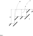
- FIG. 3 is a cross-sectional view taken along a line A-A in FIG. 2 .
- a depth d of the crown sipe 18 is preferably not less than 30% of a block height H1 of the crown block 3 and more preferably not less than 40% thereof, and preferably not greater than 70% thereof and more preferably not greater than 60% thereof.
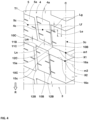
- FIG. 4 is an enlarged view of FIG. 1 .
- FIG. 4 shows the crown blocks 3, and the middle blocks 4 and the shoulder blocks 5 on the first tread end T1 side.
- a centroid 4c of a tread surface 4a of each of the plurality of middle blocks 4 and a centroid 5c of a tread surface 5a of each of the plurality of shoulder blocks 5 are each distanced from the centroid 3c of a corresponding one of the plurality of the crown blocks 3 over a certain distance in the tire circumferential direction.
- a distance Le in the tire circumferential direction between the centroid 4c of the middle block 4 and the centroid 3c of the crown block 3 is, but is not particularly limited to, preferably not less than 5.0 mm and more preferably not less than 7.0 mm, and preferably not greater than 15.0 mm and more preferably not greater than 13.0 mm.
- a distance Lf in the tire circumferential direction between the centroid 5c of the shoulder block 5 and the centroid 3c of the crown block 3 is preferably not less than 5.0 mm and more preferably not less than 7.0 mm, and preferably not greater than 15.0 mm and more preferably not greater than 13.0 mm.
- the centroid 5c of the shoulder block 5 is distanced from the centroid 4c of the middle block 4 over a certain distance in the tire circumferential direction.
- the centroid 5c of the shoulder block 5 is disposed closer to the heel side in the tire rotation direction R than the centroid 4c of the middle block 4 is.
- a distance Lg in the tire circumferential direction between the centroid 4c of the middle block 4 and the centroid 5c of the shoulder block 5 is, but is not particularly limited to, preferably not less than 2.0 mm and more preferably not less than 3.0 mm, and preferably not greater than 5.0 mm and more preferably not greater than 4.0 mm.
- each of the plurality of the middle blocks 4 and each of the plurality of the shoulder blocks 5 include a middle toe-side edge 10B and a shoulder toe-side edge 10C, respectively, disposed on the toe side in the tire rotation direction R.
- Each of the middle blocks 4 includes, for example, a middle heel-side edge 11B disposed on the heel side in the tire rotation direction R, and a pair of middle lateral edges 12B connecting between both ends of the middle toe-side edge 10B and both ends of the middle heel-side edge 11B.
- each of the shoulder blocks 5 includes, for example, a shoulder heel-side edge 11C disposed on the heel side in the tire rotation direction R, and a shoulder lateral edge 12C connecting between an inner end of the shoulder toe-side edge 10C and an inner end of the shoulder heel-side edge 11C.
- the shoulder toe-side edge 10C, and the first edge portion 16a or the second edge portion 16b are positioned on a first imaginary straight line m1.
- FIG. 4 shows the shoulder toe-side edge 10C and the first edge portion 16a that are positioned on the first imaginary straight line m1.
- FIG. 1 shows the shoulder toe-side edge 10C and the second edge portion 16b that are positioned on the first imaginary straight line m1.
- the first imaginary straight line m1 is a straight line that passes through the first connection position X1 and the first outer end 15a or passes through the first connection position X1 and the second outer end 15b.
- the phrase "positioned on the first imaginary straight line m1" means that the first imaginary straight line m1 and the shoulder toe-side edge 10C overlap each other.
- the phrase "positioned on the first imaginary straight line m1" also implies a state where a maximum distance Lm over which the first imaginary straight line m1 and the shoulder toe-side edge 10C are distant from each other in the tire circumferential direction is not greater than 2 mm.
- the shoulder toe-side edge 10C overlaps the first imaginary straight line m1.
- the middle toe-side edge 10B is disposed closer to the heel side in the tire rotation direction R than the first imaginary straight line m1 is.
- air resonance sound between the middle blocks 4 is reduced at the middle toe-side edge 10B, thereby reducing tire noise.
- the middle toe-side edge 10B is, for example, disposed so as not to come into contact with or intersect the first imaginary straight line m1.
- the above-described effect is more effectively exhibited.
- a minimum distance Ln over which the middle toe-side edge 10B and the first imaginary straight line m1 are distant from each other in the tire circumferential direction is, but is not particularly limited to, preferably not less than 1.0 mm and more preferably not less than 2.0 mm, and preferably not greater than 10.0 mm and more preferably not greater than 5.0 mm.
- the shoulder heel-side edge 11C, and the third edge portion 16c or the fourth edge portion 16d are positioned on a second imaginary straight line m2.
- FIG. 4 shows the shoulder heel-side edge 11C and the third edge portion 16c that are positioned on the second imaginary straight line m2.
- FIG. 1 shows the shoulder heel-side edge 11C and the fourth edge portion 16d that are positioned on the second imaginary straight line m2.
- the second imaginary straight line m2 is a straight line that passes through the second connection position X2 and the third outer end 15c or passes through the second connection position X2 and the fourth outer end 15d.
- the "positioned on the second imaginary straight line m2" is defined similarly to the "positioned on the first imaginary straight line m1".
- the middle heel-side edge 11B is disposed closer to the heel side in the tire rotation direction R than the second imaginary straight line m2 is.
- air resonance sound between the middle blocks 4 is reduced at the middle heel-side edge 11B, thereby further reducing tire noise.
- the middle toe-side edge 10B, the shoulder toe-side edge 10C, the middle heel-side edge 11B, and the shoulder heel-side edge 11C linearly extend outwardly in the tire axial direction toward the heel side in the tire rotation direction R.
- the middle lateral edge 12B and the shoulder lateral edge 12C linearly extend outwardly in the tire axial direction toward the heel side in the tire rotation direction R.
- FIG. 5 is an enlarged view of FIG. 1 .
- the plurality of the middle blocks 4 each have a middle sipe 20 extending in the tire axial direction.
- the middle sipe 20 is formed as a semi-open sipe that extends from the middle lateral edge 12B to the inner side of the middle block 4, and terminates in the middle block 4 without extending across the middle block 4. In the present embodiment, the middle sipe 20 linearly extends. The middle sipe 20 may extend, for example, in a wavy or zigzag manner. The middle sipe 20 is disposed in each of the pair of middle lateral edges 12B.
- An angle ⁇ 3 of the middle sipe 20 relative to the tire axial direction is preferably equal to an angle ⁇ 4 of the middle toe-side edge 10B relative to the tire axial direction.
- the term "equal” means that an absolute value
- a distance Lh in the tire axial direction between the middle sipes 20 distanced from each other in the tire axial direction is, for example, preferably not less than 10% of a maximum width Wm of the middle block 4 in the tire axial direction and more preferably not less than 15% thereof, and preferably not greater than 30% thereof and more preferably not greater than 25% thereof.
- the plurality of the shoulder blocks 5 each have a shoulder sipe 22 extending in the tire axial direction.
- the shoulder sipe 22 is formed as a semi-open sipe that extends from the shoulder lateral edge 12C, the first tread end T1, or the second tread end T2 to the inner side of the shoulder block 5, and terminates in the shoulder block 5.
- the shoulder sipe 22 linearly extends.
- the shoulder sipe 22 may extend, for example, in a wavy or zigzag manner.
- An angle ⁇ 5 of the shoulder sipe 22 relative to the tire axial direction is preferably equal to an angle ⁇ 6 of the shoulder toe-side edge 10C relative to the tire axial direction.
- the term "equal” means that an absolute value
- a distance Li in the tire axial direction between the shoulder sipes 22 distanced from each other in the tire axial direction is, for example, preferably not less than 5% of a maximum width Ws of the shoulder block 5 and more preferably not less than 10% thereof, and preferably not greater than 25% thereof and more preferably not greater than 20% thereof.
- a motorcycle rear wheel tire and a motorcycle front wheel tire each having the tread pattern shown in FIG. 1 were produced as test tires according to the specifications in Table
- test was performed in accordance with an actual vehicle coasting test specified in ASO/C/606.
- Pass-by noise maximum level dB(a)
- the results are each indicated as an index with the index of comparative example 1 being 100. The less the value is, the less tire noise is and the better the noise performance is.
- test rider drove the test vehicle on rough terrain. At this time, the test rider made a sensory evaluation for stability. The results are each indicated as a score with the score of comparative example 1 being 100. The greater the value is, the more excellent rough terrain running-through performance is.
- Table 1 indicates the test results.
- test results indicate that tire noise was low in the tires of the examples, and further indicate that the tires of the examples had excellent rough terrain running-through performance.
- the present disclosure includes the following aspects.
- a motorcycle tire including a tread portion, in which
- the motorcycle tire according to disclosure 3 in which the first crown blocks and the second crown blocks alternate in the tire circumferential direction.
- the motorcycle tire according to disclosure 5 in which the distance in the tire circumferential direction between the centroid of the tread surface of each of the plurality of middle blocks and the centroid of the tread surface of a corresponding one of the plurality of crown blocks is 5.0 to 15.0 mm.
- a length of the crown sipe in the tire axial direction is 5% to 20% of a maximum length of each crown block in the tire axial direction.
Landscapes
- Engineering & Computer Science (AREA)
- Mechanical Engineering (AREA)
- Tires In General (AREA)
Abstract
Description
- The present disclosure relates to a motorcycle tire.
- For example,
Japanese Laid-Open Patent Publication No. H02-128908 - In recent years, since quietness has been improved in a vehicle power unit, noise (tire noise) generated in the tire while the vehicle is running has also been required to be further reduced.
- The present disclosure has been made in view of the aforementioned circumstances, and a main object of the present disclosure is to provide a motorcycle tire that allows tire noise to be further reduced.
- The present disclosure is directed to a motorcycle tire including a tread portion. The tread portion has, on a tire equator, a crown block array in which a plurality of crown blocks are aligned in a tire circumferential direction. Distances in the tire circumferential direction over which the crown blocks adjacent to each other in the tire circumferential direction are distant from each other include a first distance and a second distance different from the first distance. A centroid of a tread surface of each of the plurality of crown blocks is positioned so as to be distant from the tire equator over a certain distance in a tire axial direction.
- The motorcycle tire of the present disclosure has the above-described configuration, and, therefore, can further reduce tire noise.
-
-
FIG. 1 is a development of a tread portion of a motorcycle tire according to one embodiment of the present disclosure; -
FIG. 2 is an enlarged view ofFIG. 1 ; -
FIG. 3 is a cross-sectional view taken along a line A-A inFIG. 2 ; -
FIG. 4 is an enlarged view ofFIG. 1 ; and -
FIG. 5 is an enlarged view ofFIG. 1 . - One embodiment of the present disclosure will be described below with reference to the drawings.
-
FIG. 1 is a development of atread portion 2 of a motorcycle tire 1 (hereinafter, may be simply referred to as a "tire") according to one embodiment of the present disclosure. Thetire 1 of the present embodiment is suitable for, for example, running on a course in which an on-road course and an off-road course are mixed. Thetire 1 of the present embodiment is preferably used for, for example, both a front wheel and a rear wheel of a motorcycle. - In the present embodiment, the
tread portion 2 has, on a tire equator C, acrown block array 3R in which a plurality ofcrown blocks 3 are aligned in the tire circumferential direction. Distances over which the crown blocks 3 and 3 adjacent to each other in the tire circumferential direction are distant from each other in the tire circumferential direction include a first distance La1 and a second distance La2 different from the first distance La1. Thus, a time interval of air compression/release generated between thecrown blocks tire 1 may include four kinds of distances that are the first distance La1, the second distance La2, the third distance La3, and a fourth distance (not shown) different from each of the first, the second, and the third distances La1, La2, and La3. - A centroid 3c of a
tread surface 3a of each of the plurality ofcrown blocks 3 is positioned so as to be distant from the tire equator C over a distance Lb in the tire axial direction. Thus, noise generated when air is compressed/released between thecrown blocks crown block 3. By combining this difference with variation of the time interval, concentration of noise in a specific frequency range is further inhibited. As described above, thetire 1 of the present embodiment allows tire noise to be further reduced. - If the distance Lb is excessively great, running balance during straight running is degraded, and rough terrain running-through performance may be degraded. Therefore, the distance Lb is preferably not less than 1.0 mm and more preferably not less than 2.0 mm, and preferably not greater than 15.0 mm and more preferably not greater than 10.0 mm.
- The
tread portion 2 has, for example, a directional pattern in which the tire rotation direction R is designated. However, thetire 1 of the present disclosure is not limited to a tire having a designated tire rotation direction. - In the present embodiment, the
tread portion 2 includes a pair ofmiddle block arrays 4R and a pair ofshoulder block arrays 5R. The pair ofmiddle block arrays 4R are disposed on both outer sides of thecrown block 3 in the tire axial direction. Eachmiddle block array 4R has a plurality ofmiddle blocks 4 aligned in the tire circumferential direction. The pair ofshoulder block arrays 5R are disposed outward of themiddle blocks 4 in the tire axial direction. Eachshoulder block array 5R has a plurality ofshoulder blocks 5 aligned in the tire circumferential direction. - The
tread portion 2 includes a first tread end T1 (left side in the drawings) and a second tread end T2. Thecrown blocks 3 include a plurality offirst crown blocks 3A each having the centroid 3c disposed on the first tread end T1 side relative to the tire equator C, and a plurality ofsecond crown blocks 3B each having thecentroid 3c disposed on the second tread end T2 side relative to the tire equator C. - The first crown blocks 3A and the
second crown blocks 3B alternate in the tire circumferential direction. Thus, noise generated when air is compressed/released between thecrown blocks - The first tread end T1 and the second tread end T2 correspond to both ends in the tire axial direction in the normal state of the
tire 1. The "normal state" represents a state in which thetire 1 is mounted on a normal rim (not shown) and is inflated to a normal internal pressure, and no load is applied. In the description herein, unless otherwise specified, dimensions of components of thetire 1 are represented as values measured in the normal state. - The "normal rim" represents a rim that is defined in a standard system including a standard on which the tire is based, by the standard, for each tire, and is, for example, the "standard rim" in the JATMA standard, the "Design Rim" in the TRA standard, or the "Measuring Rim" in the ETRTO standard.
- The "normal internal pressure" represents an air pressure that is defined in a standard system including a standard on which the tire is based, by the standard, for each tire, and is the "maximum air pressure" in the JATMA standard, the maximum value recited in the table "TIRE LOAD LIMITS AT VARIOUS COLD INFLATION PRESSURES" in the TRA standard, or the "INFLATION PRESSURE" in the ETRTO standard.
-
FIG. 2 is an enlarged view ofFIG. 1 . As shown inFIG. 2 , the plurality of thecrown blocks 3 each include, for example, a crown toe-side edge 10A disposed on a toe side in the tire rotation direction R. In the present embodiment, each of thecrown blocks 3 includes a crown heel-side edge 11A disposed on a heel side in the tire rotation direction R, and a pair of crownlateral edges 12A connecting between both ends of the crown toe-side edge 10A and both ends of the crown heel-side edge 11A. - The crown toe-
side edge 10A is, for example, inclined relative to the tire axial direction. Thus, the entirety of the crown toe-side edge 10A is inhibited from simultaneously coming into contact with a road surface when thecrown block 3 comes into contact with the ground, so that impact sound becomes low to further reduce tire noise. - If an angle θ1 of the crown toe-
side edge 10A relative to the tire axial direction is excessively great, traction by the crown toe-side edge 10A may be reduced. Therefore, the angle θ1 of the crown toe-side edge 10A is preferably not less than 10° and more preferably not less than 20°, and preferably not greater than 45° and more preferably not greater than 35°. - The crown toe-
side edge 10A extends from a firstouter end 15a (left side in the drawings) to a secondouter end 15b (right side in the drawings) in the tire axial direction so as to be V-shaped. The crown toe-side edge 10A includes afirst edge portion 16a that linearly extends from the firstouter end 15a toward the tire equator C, and asecond edge portion 16b that linearly extends from the secondouter end 15b toward the tire equator C. The term "linearly" implies a straight line, and a curved line formed of a single arc in which a curvature radius is not less than 200 mm. - The
first edge portion 16a and thesecond edge portion 16b connect to each other at a position (first connection position) X1 distant from the tire equator C over a distance Lc in the tire axial direction. Thus, concentration of noise in a specific frequency range can be further inhibited. In order to exhibit such an effect, the distance Lc in the tire axial direction between the first connection position X1 and the tire equator C is preferably not less than 1% of a maximum width Wc of thecrown block 3 in the tire axial direction and more preferably not less than 2% thereof, and preferably not greater than 5% thereof and more preferably not greater than 4% thereof. - The crown heel-
side edge 11A extends from a thirdouter end 15c (left side in the drawings) to a fourthouter end 15d in the tire axial direction so as to be V-shaped. The crown heel-side edge 11A includes athird edge portion 16c that linearly extends from the thirdouter end 15c toward the tire equator C, and afourth edge portion 16d that linearly extends from the fourthouter end 15d toward the tire equator C. In the present embodiment, thethird edge portion 16c and thefourth edge portion 16d are inclined relative to the tire axial direction. - For example, the
third edge portion 16c and thefourth edge portion 16d connect to each other at a position (second connection position) X2 distant from the tire equator C over a distance Ld in the tire axial direction. The second connection position X2 is positioned on the same side as the first connection position X1 relative to the tire equator C in the tire axial direction. The distance Ld is preferably equal to the distance Lc. - In the present embodiment, each crown
lateral edge 12A linearly extends. For example, each crownlateral edge 12A extends outward in the tire axial direction toward the heel side in the tire rotation direction R. - The plurality of the crown blocks 3 each have a
crown sipe 18 extending in the tire axial direction. Thecrown sipe 18 contributes to proper reduction of stiffness of thecrown block 3, and reduction of impact sound during contact with a road surface. In the description herein, sipes including amiddle sipe 20 and ashoulder sipe 22 described below each represent a cut recess having a width of not greater than 1.5 mm, and are clearly distinguished from a groove in which a width for demarcating each block is not less than 1.5 mm. - The
crown sipe 18 is formed as a semi-open sipe that extends from thecrown lateral edge 12A and terminates in thetread surface 3a of thecrown block 3 without reaching the tire equator C. Therefore, reduction of stiffness of thecrown block 3 is inhibited, and running performance (rough terrain running-through performance) is thus stabilized in rough terrain. In the present embodiment, thecrown sipe 18 linearly extends. Thecrown sipe 18 may extend, for example, in a wavy or zigzag manner. - An angle θ2 of the
crown sipe 18 relative to the tire axial direction is preferably equal to the angle θ1 of the crown toe-side edge 10A. Thus, an edge effect is enhanced, and rough terrain running-through performance becomes excellent. The term "equal" means that an absolute value |θ2-θ1| of a difference between the angle θ2 of thecrown sipe 18 and the angle θ1 of the crown toe-side edge 10A is 0°, and also means the absolute value is not greater than 10°. - In order to effectively exhibit the above-described effect, a length L1 of the
crown sipe 18 in the tire axial direction is preferably not less than 5% of the maximum width Wc of thecrown block 3 in the tire axial direction and more preferably not less than 10% thereof, and preferably not greater than 20% thereof and more preferably not greater than 15% thereof. -
FIG. 3 is a cross-sectional view taken along a line A-A inFIG. 2 . As shown inFIG. 3 , a depth d of thecrown sipe 18 is preferably not less than 30% of a block height H1 of thecrown block 3 and more preferably not less than 40% thereof, and preferably not greater than 70% thereof and more preferably not greater than 60% thereof. -
FIG. 4 is an enlarged view ofFIG. 1 .FIG. 4 shows the crown blocks 3, and the middle blocks 4 and the shoulder blocks 5 on the first tread end T1 side. As shown inFIG. 4 , acentroid 4c of atread surface 4a of each of the plurality ofmiddle blocks 4 and acentroid 5c of atread surface 5a of each of the plurality ofshoulder blocks 5 are each distanced from thecentroid 3c of a corresponding one of the plurality of the crown blocks 3 over a certain distance in the tire circumferential direction. Thus, a portion at which impact sound between thecrown block 3 and a road surface is high, and a portion at which impact sound between themiddle block 4 and theshoulder block 5, and the road surface is high, are shifted in the tire circumferential direction, thereby further reducing tire noise. - A distance Le in the tire circumferential direction between the
centroid 4c of themiddle block 4 and thecentroid 3c of thecrown block 3 is, but is not particularly limited to, preferably not less than 5.0 mm and more preferably not less than 7.0 mm, and preferably not greater than 15.0 mm and more preferably not greater than 13.0 mm. From the same viewpoint, a distance Lf in the tire circumferential direction between thecentroid 5c of theshoulder block 5 and thecentroid 3c of thecrown block 3 is preferably not less than 5.0 mm and more preferably not less than 7.0 mm, and preferably not greater than 15.0 mm and more preferably not greater than 13.0 mm. - In the present embodiment, the
centroid 5c of theshoulder block 5 is distanced from thecentroid 4c of themiddle block 4 over a certain distance in the tire circumferential direction. For example, thecentroid 5c of theshoulder block 5 is disposed closer to the heel side in the tire rotation direction R than thecentroid 4c of themiddle block 4 is. A distance Lg in the tire circumferential direction between thecentroid 4c of themiddle block 4 and thecentroid 5c of theshoulder block 5 is, but is not particularly limited to, preferably not less than 2.0 mm and more preferably not less than 3.0 mm, and preferably not greater than 5.0 mm and more preferably not greater than 4.0 mm. - In the present embodiment, each of the plurality of the middle blocks 4 and each of the plurality of the
shoulder blocks 5 include a middle toe-side edge 10B and a shoulder toe-side edge 10C, respectively, disposed on the toe side in the tire rotation direction R. Each of the middle blocks 4 includes, for example, a middle heel-side edge 11B disposed on the heel side in the tire rotation direction R, and a pair of middle lateral edges 12B connecting between both ends of the middle toe-side edge 10B and both ends of the middle heel-side edge 11B. Furthermore, each of the shoulder blocks 5 includes, for example, a shoulder heel-side edge 11C disposed on the heel side in the tire rotation direction R, and a shoulderlateral edge 12C connecting between an inner end of the shoulder toe-side edge 10C and an inner end of the shoulder heel-side edge 11C. - The shoulder toe-
side edge 10C, and thefirst edge portion 16a or thesecond edge portion 16b are positioned on a first imaginary straight line m1.FIG. 4 shows the shoulder toe-side edge 10C and thefirst edge portion 16a that are positioned on the first imaginary straight line m1.FIG. 1 shows the shoulder toe-side edge 10C and thesecond edge portion 16b that are positioned on the first imaginary straight line m1. The first imaginary straight line m1 is a straight line that passes through the first connection position X1 and the firstouter end 15a or passes through the first connection position X1 and the secondouter end 15b. The phrase "positioned on the first imaginary straight line m1" means that the first imaginary straight line m1 and the shoulder toe-side edge 10C overlap each other. Furthermore, the phrase "positioned on the first imaginary straight line m1" also implies a state where a maximum distance Lm over which the first imaginary straight line m1 and the shoulder toe-side edge 10C are distant from each other in the tire circumferential direction is not greater than 2 mm. In the present embodiment, the shoulder toe-side edge 10C overlaps the first imaginary straight line m1. - In the present embodiment, the middle toe-
side edge 10B is disposed closer to the heel side in the tire rotation direction R than the first imaginary straight line m1 is. Thus, air resonance sound between themiddle blocks 4 is reduced at the middle toe-side edge 10B, thereby reducing tire noise. The middle toe-side edge 10B is, for example, disposed so as not to come into contact with or intersect the first imaginary straight line m1. Thus, the above-described effect is more effectively exhibited. A minimum distance Ln over which the middle toe-side edge 10B and the first imaginary straight line m1 are distant from each other in the tire circumferential direction is, but is not particularly limited to, preferably not less than 1.0 mm and more preferably not less than 2.0 mm, and preferably not greater than 10.0 mm and more preferably not greater than 5.0 mm. - The shoulder heel-
side edge 11C, and thethird edge portion 16c or thefourth edge portion 16d are positioned on a second imaginary straight line m2.FIG. 4 shows the shoulder heel-side edge 11C and thethird edge portion 16c that are positioned on the second imaginary straight line m2.FIG. 1 shows the shoulder heel-side edge 11C and thefourth edge portion 16d that are positioned on the second imaginary straight line m2. The second imaginary straight line m2 is a straight line that passes through the second connection position X2 and the thirdouter end 15c or passes through the second connection position X2 and the fourthouter end 15d. The "positioned on the second imaginary straight line m2" is defined similarly to the "positioned on the first imaginary straight line m1". - In the present embodiment, the middle heel-
side edge 11B is disposed closer to the heel side in the tire rotation direction R than the second imaginary straight line m2 is. Thus, air resonance sound between themiddle blocks 4 is reduced at the middle heel-side edge 11B, thereby further reducing tire noise. - In the present embodiment, the middle toe-
side edge 10B, the shoulder toe-side edge 10C, the middle heel-side edge 11B, and the shoulder heel-side edge 11C linearly extend outwardly in the tire axial direction toward the heel side in the tire rotation direction R. For example, the middlelateral edge 12B and the shoulderlateral edge 12C linearly extend outwardly in the tire axial direction toward the heel side in the tire rotation direction R. -
FIG. 5 is an enlarged view ofFIG. 1 . As shown inFIG. 5 , the plurality of the middle blocks 4 each have amiddle sipe 20 extending in the tire axial direction. - The
middle sipe 20 is formed as a semi-open sipe that extends from the middlelateral edge 12B to the inner side of themiddle block 4, and terminates in themiddle block 4 without extending across themiddle block 4. In the present embodiment, themiddle sipe 20 linearly extends. Themiddle sipe 20 may extend, for example, in a wavy or zigzag manner. Themiddle sipe 20 is disposed in each of the pair of middle lateral edges 12B. - An angle θ3 of the
middle sipe 20 relative to the tire axial direction is preferably equal to an angle θ4 of the middle toe-side edge 10B relative to the tire axial direction. Thus, rough terrain running-through performance can be further enhanced. The term "equal" means that an absolute value |θ3-θ4| of a difference between the angle θ3 of themiddle sipe 20 and the angle θ4 of the middle toe-side edge 10B is not greater than 10°. - A distance Lh in the tire axial direction between the
middle sipes 20 distanced from each other in the tire axial direction is, for example, preferably not less than 10% of a maximum width Wm of themiddle block 4 in the tire axial direction and more preferably not less than 15% thereof, and preferably not greater than 30% thereof and more preferably not greater than 25% thereof. - In the present embodiment, the plurality of the
shoulder blocks 5 each have ashoulder sipe 22 extending in the tire axial direction. - The
shoulder sipe 22 is formed as a semi-open sipe that extends from the shoulderlateral edge 12C, the first tread end T1, or the second tread end T2 to the inner side of theshoulder block 5, and terminates in theshoulder block 5. In the present embodiment, theshoulder sipe 22 linearly extends. Theshoulder sipe 22 may extend, for example, in a wavy or zigzag manner. - An angle θ5 of the
shoulder sipe 22 relative to the tire axial direction is preferably equal to an angle θ6 of the shoulder toe-side edge 10C relative to the tire axial direction. Thus, rough terrain running-through performance is enhanced. The term "equal" means that an absolute value |θ5-θ6| of a difference between the angle θ5 of theshoulder sipe 22 and the angle θ6 of the shoulder toe-side edge 10C is not greater than 10°. - A distance Li in the tire axial direction between the
shoulder sipes 22 distanced from each other in the tire axial direction is, for example, preferably not less than 5% of a maximum width Ws of theshoulder block 5 and more preferably not less than 10% thereof, and preferably not greater than 25% thereof and more preferably not greater than 20% thereof. - Although the particularly preferred embodiment of the present disclosure has been described above in detail, the present disclosure is not limited to the above-described embodiment, and various modifications can be made to implement the technique of the present disclosure.
- A motorcycle rear wheel tire and a motorcycle front wheel tire each having the tread pattern shown in
FIG. 1 were produced as test tires according to the specifications in Table - 1. Each test tire was tested for noise performance and rough terrain running-through performance. Specifications common to the test tires were as follows.
- Tire size
- Front wheel: 120/70R17
- Rear wheel: 160/60R17
- Rim size
- Front wheel: 3.50×17
- Rear wheel: 4.50×17
- Tire internal pressure
- Front wheel: 250 kPa
- Rear wheel: 250 kPa
- The test methods were as follows.
- Tire size
- The test was performed in accordance with an actual vehicle coasting test specified in ASO/C/606. Pass-by noise (maximum level dB(a)) was measured by a stationary microphone when the test vehicle was coasted under the following conditions. The results are each indicated as an index with the index of comparative example 1 being 100. The less the value is, the less tire noise is and the better the noise performance is.
- Test vehicle: motorcycle having engine displacement of 500 cc
- Road on which the test vehicle ran: dry asphalt road surface
- Coasting distance: 50 m
- Passing speed: 60 km/h
- Position of stationary microphone: position that was distant laterally from the travel center line over 7.5 m and was 1.2 m high from the road surface
- A test rider drove the test vehicle on rough terrain. At this time, the test rider made a sensory evaluation for stability. The results are each indicated as a score with the score of comparative example 1 being 100. The greater the value is, the more excellent rough terrain running-through performance is.
- Table 1 indicates the test results.
- In Table 1, "A" indicates that the centroid of the crown block was distant from the tire equator, and
- "B" indicates that the centroid of the crown block was on the tire equator.
- In Table 1, "C" indicates that the centroid of the middle block and the centroid of the shoulder block, and the centroid of the crown block were shifted from each other in the tire circumferential direction, and "D" indicates that the centroid of the middle block and the centroid of the shoulder block, and the centroid of the crown block were not shifted from each other in the tire circumferential direction.
[Table 1] Comp. Ex. 1 Comp. Ex. 2 Ex. 1 Ex. 2 Ex. 3 Kinds of distances over which crown blocks were distanced 1 1 2 3 3 Position of centroid of crown block (A or B) B B A A A Position of centroid of middle block (C or D) D D D D C Position of centroid of shoulder block (C or D) D D D D C θ1 (°) 0 10 20 20 20 Presence or absence of crown sipe Absent Absent Absent Absent Present Noise performance [Index, the less the value is, the better the noise performance is] 100 90 80 70 65 Rough terrain running-through performance [Score, the greater the value is, the better the performance is] 100 100 100 100 100 - The test results indicate that tire noise was low in the tires of the examples, and further indicate that the tires of the examples had excellent rough terrain running-through performance.
- The present disclosure includes the following aspects.
- A motorcycle tire including a tread portion, in which
- the tread portion has, on a tire equator, a crown block array in which a plurality of crown blocks are aligned in a tire circumferential direction,
- distances in the tire circumferential direction over which the crown blocks adjacent to each other in the tire circumferential direction are distant from each other include a first distance and a second distance different from the first distance, and
- a centroid of a tread surface of each of the plurality of crown blocks is positioned so as to be distant from the tire equator over a certain distance in a tire axial direction.
- The motorcycle tire according to
disclosure 1, in which the distance between the tire equator and the centroid of each crown block is 1.0 to 15.0 mm. - The motorcycle tire according to
disclosure - the tread portion includes a first tread end and a second tread end, and
- the crown blocks include a plurality of first crown blocks each having the centroid disposed on the first tread end side relative to the tire equator, and a plurality of second crown blocks each having the centroid disposed on the second tread end side relative to the tire equator.
- The motorcycle tire according to
disclosure 3, in which the first crown blocks and the second crown blocks alternate in the tire circumferential direction. - The motorcycle tire according to any one of
disclosures 1 to 4, in which - the tread portion includes a pair of middle block arrays each of which is disposed outward of the crown blocks in the tire axial direction and has a plurality of middle blocks aligned in the tire circumferential direction, and includes a pair of shoulder block arrays each of which is disposed outward of the middle blocks in the tire axial direction and has a plurality of shoulder blocks aligned in the tire circumferential direction, and
- a centroid of a tread surface of each of the plurality of middle blocks and a centroid of a tread surface of each of the plurality of shoulder blocks are each distanced from the centroid of the tread surface of a corresponding one of the plurality of crown blocks, over a certain distance, in the tire circumferential direction.
- The motorcycle tire according to
disclosure 5, in which the distance in the tire circumferential direction between the centroid of the tread surface of each of the plurality of middle blocks and the centroid of the tread surface of a corresponding one of the plurality of crown blocks is 5.0 to 15.0 mm. - The motorcycle tire according to
disclosure 5 or 6, in which the distance in the tire circumferential direction between the centroid of the tread surface of each of the plurality of shoulder blocks and the centroid of the tread surface of a corresponding one of the plurality of crown blocks is 5.0 to 15.0 mm. - The motorcycle tire according to any one of
disclosures 1 to 7, in which - the tread portion has a designated tire rotation direction,
- the plurality of crown blocks each include a crown toe-side edge disposed on a toe side in the tire rotation direction, and
- the crown toe-side edge is inclined relative to the tire axial direction.
- The motorcycle tire according to disclosure 8, in which an angle of the crown toe-side edge relative to the tire axial direction is 10 to 45°.
- The motorcycle tire according to disclosure 8 or 9, in which
- the crown toe-side edge extends from a first outer end to a second outer end in the tire axial direction so as to be V-shaped,
- the crown toe-side edge includes a first edge portion that linearly extends from the first outer end toward the tire equator, and a second edge portion that linearly extends from the second outer end toward the tire equator, and
- the first edge portion and the second edge portion connect to each other at a position distant from the tire equator over a certain distance in the tire axial direction.
- The motorcycle tire according to disclosure 10, in which
- the tread portion includes a pair of middle block arrays each of which is disposed outward of the crown blocks in the tire axial direction and has a plurality of middle blocks aligned in the tire circumferential direction, and includes a pair of shoulder block arrays each of which is disposed outward of the middle blocks in the tire axial direction and has a plurality of shoulder blocks aligned in the tire circumferential direction,
- each of the plurality of middle blocks and each of the plurality of shoulder blocks include a middle toe-side edge and a shoulder toe-side edge, respectively, disposed on a toe side in the tire rotation direction,
- the first edge portion or the second edge portion, and the shoulder toe-side edge are positioned on a first imaginary straight line, and
- the middle toe-side edge is disposed closer to a heel side in tire rotation direction than the first imaginary straight line is.
- The motorcycle tire according to any one of
disclosures 1 to 11, in which - the plurality of crown blocks each have a crown sipe extending in the tire axial direction, and
- a depth of the crown sipe is 30% to 70% of a block height of each crown block.
- The motorcycle tire according to disclosure 12, in which a length of the crown sipe in the tire axial direction is 5% to 20% of a maximum length of each crown block in the tire axial direction.
Claims (13)
- A motorcycle tire (1) comprisinga tread portion (2), whereinthe tread portion (2) has, on a tire equator (C), a crown block array (3R) in which a plurality of crown blocks (3) are aligned in a tire circumferential direction,distances in the tire circumferential direction over which the crown blocks (3) adjacent to each other in the tire circumferential direction are distant from each other include a first distance (La1) and a second distance (La2) different from the first distance (La1), anda centroid (3c) of a tread surface (3a) of each of the plurality of crown blocks (3) is positioned so as to be distant from the tire equator (C) over a certain distance (Lb) in a tire axial direction.
- The motorcycle tire (1) according to claim 1, wherein the distance (Lb) between the tire equator (C) and the centroid (3c) of each crown block (3) is 1.0 to 15.0 mm.
- The motorcycle tire (1) according to claim 1 or 2, whereinthe tread portion (2) includes a first tread end (T1) and a second tread end (T2), andthe crown blocks (3) include a plurality of first crown blocks (3A) each having the centroid (3c) disposed on the first tread end (T1) side relative to the tire equator (C), and a plurality of second crown blocks (3B) each having the centroid (3c) disposed on the second tread end (T2) side relative to the tire equator (C).
- The motorcycle tire (1) according to claim 3, wherein the first crown blocks (3A) and the second crown blocks (3B) alternate in the tire circumferential direction.
- The motorcycle tire (1) according to any one of claims 1 to 4, whereinthe tread portion (2) includes a pair of middle block arrays (4R) each of which is disposed outward of the crown blocks (3) in the tire axial direction and has a plurality of middle blocks (4) aligned in the tire circumferential direction, and includes a pair of shoulder block arrays (5R) each of which is disposed outward of the middle blocks (4) in the tire axial direction and has a plurality of shoulder blocks (5) aligned in the tire circumferential direction, anda centroid (4c) of a tread surface (4a) of each of the plurality of middle blocks (4) and a centroid (5c) of a tread surface (5a) of each of the plurality of shoulder blocks (5) are each distanced from the centroid (3c) of the tread surface (3a) of a corresponding one of the plurality of crown blocks (3), over a certain distance, in the tire circumferential direction.
- The motorcycle tire (1) according to claim 5, wherein the distance (Le) in the tire circumferential direction between the centroid (4c) of the tread surface (4a) of each of the plurality of middle blocks (4) and the centroid (3c) of the tread surface (3a) of a corresponding one of the plurality of crown blocks (3) is 5.0 to 15.0 mm.
- The motorcycle tire (1) according to claim 5 or 6, wherein the distance (Lf) in the tire circumferential direction between the centroid (5c) of the tread surface (5a) of each of the plurality of shoulder blocks (5) and the centroid (3c) of the tread surface (3a) of a corresponding one of the plurality of crown blocks (3) is 5.0 to 15.0 mm.
- The motorcycle tire (1) according to any one of claims 1 to 7, whereinthe tread portion (2) has a designated tire rotation direction (R),the plurality of crown blocks (3) each include a crown toe-side edge (10A) disposed on a toe side in the tire rotation direction (R), andthe crown toe-side edge (10A) is inclined relative to the tire axial direction.
- The motorcycle tire (1) according to claim 8, wherein an angle (θ1) of the crown toe-side edge (10A) relative to the tire axial direction is 10 to 45°.
- The motorcycle tire (1) according to claim 8 or 9, whereinthe crown toe-side edge (10A) extends from a first outer end (15a) to a second outer end (15b) in the tire axial direction so as to be V-shaped,the crown toe-side edge (10A) includes a first edge portion (16a) that linearly extends from the first outer end (15a) toward the tire equator (C), and a second edge portion (16b) that linearly extends from the second outer end (15b) toward the tire equator (C), andthe first edge portion (16a) and the second edge portion (16b) connect to each other at a position (X1) distant from the tire equator (C) over a certain distance (Lc) in the tire axial direction.
- The motorcycle tire (1) according to claim 10, whereinthe tread portion (2) includes a pair of middle block arrays (4R) each of which is disposed outward of the crown blocks (3) in the tire axial direction and has a plurality of middle blocks (4) aligned in the tire circumferential direction, and includes a pair of shoulder block arrays (5R) each of which is disposed outward of the middle blocks (4) in the tire axial direction and has a plurality of shoulder blocks (5) aligned in the tire circumferential direction,each of the plurality of middle blocks (4) and each of the plurality of shoulder blocks (5) include a middle toe-side edge (10B) and a shoulder toe-side edge (10C), respectively, disposed on a toe side in the tire rotation direction (R),the first edge portion (16a) or the second edge portion (16b), and the shoulder toe-side edge (10C) are positioned on a first imaginary straight line (m1), andthe middle toe-side edge (10B) is disposed closer to a heel side in tire rotation direction (R) than the first imaginary straight line (m1) is.
- The motorcycle tire (1) according to any one of claims 1 to 11, whereinthe plurality of crown blocks (3) each have a crown sipe (18) extending in the tire axial direction, anda depth (d) of the crown sipe (18) is 30% to 70% of a block height (H1) of each crown block (3).
- The motorcycle tire (1) according to claim 12, wherein a length (L1) of the crown sipe (18) in the tire axial direction is 5% to 20% of a maximum length (Wc) of each crown block (3) in the tire axial direction.
Applications Claiming Priority (1)
| Application Number | Priority Date | Filing Date | Title |
|---|---|---|---|
| JP2022003235A JP2023102628A (en) | 2022-01-12 | 2022-01-12 | motorcycle tire |
Publications (2)
| Publication Number | Publication Date |
|---|---|
| EP4212360A1 true EP4212360A1 (en) | 2023-07-19 |
| EP4212360B1 EP4212360B1 (en) | 2025-01-01 |
Family
ID=84359049
Family Applications (1)
| Application Number | Title | Priority Date | Filing Date |
|---|---|---|---|
| EP22207811.5A Active EP4212360B1 (en) | 2022-01-12 | 2022-11-16 | Motorcycle tire |
Country Status (3)
| Country | Link |
|---|---|
| EP (1) | EP4212360B1 (en) |
| JP (1) | JP2023102628A (en) |
| CN (1) | CN116424034A (en) |
Families Citing this family (1)
| Publication number | Priority date | Publication date | Assignee | Title |
|---|---|---|---|---|
| JP2025091218A (en) | 2023-12-06 | 2025-06-18 | 住友ゴム工業株式会社 | Motorcycle tire |
Citations (6)
| Publication number | Priority date | Publication date | Assignee | Title |
|---|---|---|---|---|
| JPH02128908A (en) | 1988-11-09 | 1990-05-17 | Sumitomo Rubber Ind Ltd | Tire for motorcycle |
| US5318086A (en) * | 1987-12-17 | 1994-06-07 | Bridgestone Corporation | Pneumatic off-the-road tires |
| JP2001071711A (en) * | 1999-09-07 | 2001-03-21 | Bridgestone Corp | Pneumatic tire for two-wheeled vehicle |
| JP2006076520A (en) * | 2004-09-13 | 2006-03-23 | Bridgestone Corp | Rear tire for bicycle |
| US9937755B2 (en) * | 2013-09-20 | 2018-04-10 | Sumitomo Rubber Industries Ltd. | Motorcycle tire |
| US10464375B2 (en) * | 2015-02-10 | 2019-11-05 | Sumitomo Rubber Industries, Ltd. | Motorcycle tire |
Family Cites Families (8)
| Publication number | Priority date | Publication date | Assignee | Title |
|---|---|---|---|---|
| JPS59220405A (en) * | 1983-05-28 | 1984-12-11 | Honda Motor Co Ltd | Motorcycle tire |
| JPS6052104U (en) * | 1983-09-20 | 1985-04-12 | 住友ゴム工業株式会社 | low noise tires |
| JPS6136002A (en) * | 1984-07-27 | 1986-02-20 | Bridgestone Corp | Motorcycle belted tire excellent in grounding characteristic |
| US5088535A (en) * | 1988-11-02 | 1992-02-18 | Specialized Bicycle Components, Inc. | Bicycle or motorcycle tire tread |
| JP3643152B2 (en) * | 1995-10-24 | 2005-04-27 | 株式会社ブリヂストン | Pneumatic tire for motorcycle |
| JP4369249B2 (en) * | 2004-01-07 | 2009-11-18 | 株式会社ブリヂストン | Pneumatic tire for two-wheeled vehicle and mounting method thereof |
| JP7000846B2 (en) * | 2017-12-25 | 2022-01-19 | 住友ゴム工業株式会社 | Motorcycle tires |
| WO2020031640A1 (en) * | 2018-08-09 | 2020-02-13 | 株式会社ブリヂストン | Motorcycle tire |
-
2022
- 2022-01-12 JP JP2022003235A patent/JP2023102628A/en active Pending
- 2022-11-16 EP EP22207811.5A patent/EP4212360B1/en active Active
- 2022-12-09 CN CN202211580045.1A patent/CN116424034A/en active Pending
Patent Citations (6)
| Publication number | Priority date | Publication date | Assignee | Title |
|---|---|---|---|---|
| US5318086A (en) * | 1987-12-17 | 1994-06-07 | Bridgestone Corporation | Pneumatic off-the-road tires |
| JPH02128908A (en) | 1988-11-09 | 1990-05-17 | Sumitomo Rubber Ind Ltd | Tire for motorcycle |
| JP2001071711A (en) * | 1999-09-07 | 2001-03-21 | Bridgestone Corp | Pneumatic tire for two-wheeled vehicle |
| JP2006076520A (en) * | 2004-09-13 | 2006-03-23 | Bridgestone Corp | Rear tire for bicycle |
| US9937755B2 (en) * | 2013-09-20 | 2018-04-10 | Sumitomo Rubber Industries Ltd. | Motorcycle tire |
| US10464375B2 (en) * | 2015-02-10 | 2019-11-05 | Sumitomo Rubber Industries, Ltd. | Motorcycle tire |
Also Published As
| Publication number | Publication date |
|---|---|
| CN116424034A (en) | 2023-07-14 |
| EP4212360B1 (en) | 2025-01-01 |
| JP2023102628A (en) | 2023-07-25 |
Similar Documents
| Publication | Publication Date | Title |
|---|---|---|
| US10800212B2 (en) | Pneumatic tire | |
| EP1437237B1 (en) | Pneumatic tire | |
| EP3539798A1 (en) | Tyre | |
| EP3388255B1 (en) | Pneumatic tire | |
| EP4406762B1 (en) | Motorcycle tire set | |
| US20170113493A1 (en) | Tire | |
| US11541692B2 (en) | Tyre | |
| US11975569B2 (en) | Pneumatic tire | |
| US20240246366A1 (en) | Motorcycle tire set | |
| US11571933B2 (en) | Tire | |
| EP3603992A1 (en) | Tyre for running on rough terrain | |
| EP4212360B1 (en) | Motorcycle tire | |
| US11618284B2 (en) | Tire | |
| EP3611037B1 (en) | Tyre for running on rough terrain | |
| EP4074522B1 (en) | Tyre | |
| US11607914B2 (en) | Two-wheeled vehicle tire | |
| US11135877B2 (en) | Tire | |
| EP3597451A1 (en) | Tyre | |
| EP3970996B1 (en) | Tire | |
| EP4151435A1 (en) | Tire | |
| EP4151432A1 (en) | Tire | |
| EP3689641B1 (en) | Tire tread | |
| US11745547B2 (en) | Tyre | |
| US20200254821A1 (en) | Tyre | |
| EP3925800B1 (en) | Tire |
Legal Events
| Date | Code | Title | Description |
|---|---|---|---|
| PUAI | Public reference made under article 153(3) epc to a published international application that has entered the european phase |
Free format text: ORIGINAL CODE: 0009012 |
|
| STAA | Information on the status of an ep patent application or granted ep patent |
Free format text: STATUS: THE APPLICATION HAS BEEN PUBLISHED |
|
| AK | Designated contracting states |
Kind code of ref document: A1 Designated state(s): AL AT BE BG CH CY CZ DE DK EE ES FI FR GB GR HR HU IE IS IT LI LT LU LV MC ME MK MT NL NO PL PT RO RS SE SI SK SM TR |
|
| STAA | Information on the status of an ep patent application or granted ep patent |
Free format text: STATUS: REQUEST FOR EXAMINATION WAS MADE |
|
| 17P | Request for examination filed |
Effective date: 20230927 |
|
| RBV | Designated contracting states (corrected) |
Designated state(s): AL AT BE BG CH CY CZ DE DK EE ES FI FR GB GR HR HU IE IS IT LI LT LU LV MC ME MK MT NL NO PL PT RO RS SE SI SK SM TR |
|
| P01 | Opt-out of the competence of the unified patent court (upc) registered |
Effective date: 20240327 |
|
| GRAP | Despatch of communication of intention to grant a patent |
Free format text: ORIGINAL CODE: EPIDOSNIGR1 |
|
| STAA | Information on the status of an ep patent application or granted ep patent |
Free format text: STATUS: GRANT OF PATENT IS INTENDED |
|
| RIC1 | Information provided on ipc code assigned before grant |
Ipc: B60C 11/12 20060101ALI20240814BHEP Ipc: B60C 11/11 20060101ALI20240814BHEP Ipc: B60C 11/03 20060101AFI20240814BHEP |
|
| INTG | Intention to grant announced |
Effective date: 20240912 |
|
| GRAS | Grant fee paid |
Free format text: ORIGINAL CODE: EPIDOSNIGR3 |
|
| GRAA | (expected) grant |
Free format text: ORIGINAL CODE: 0009210 |
|
| STAA | Information on the status of an ep patent application or granted ep patent |
Free format text: STATUS: THE PATENT HAS BEEN GRANTED |
|
| AK | Designated contracting states |
Kind code of ref document: B1 Designated state(s): AL AT BE BG CH CY CZ DE DK EE ES FI FR GB GR HR HU IE IS IT LI LT LU LV MC ME MK MT NL NO PL PT RO RS SE SI SK SM TR |
|
| REG | Reference to a national code |
Ref country code: GB Ref legal event code: FG4D |
|
| REG | Reference to a national code |
Ref country code: CH Ref legal event code: EP |
|
| REG | Reference to a national code |
Ref country code: DE Ref legal event code: R096 Ref document number: 602022009311 Country of ref document: DE |
|
| REG | Reference to a national code |
Ref country code: IE Ref legal event code: FG4D |
|
| REG | Reference to a national code |
Ref country code: LT Ref legal event code: MG9D |
|
| REG | Reference to a national code |
Ref country code: NL Ref legal event code: MP Effective date: 20250101 |
|
| REG | Reference to a national code |
Ref country code: AT Ref legal event code: MK05 Ref document number: 1755883 Country of ref document: AT Kind code of ref document: T Effective date: 20250101 |
|
| PG25 | Lapsed in a contracting state [announced via postgrant information from national office to epo] |
Ref country code: NL Free format text: LAPSE BECAUSE OF FAILURE TO SUBMIT A TRANSLATION OF THE DESCRIPTION OR TO PAY THE FEE WITHIN THE PRESCRIBED TIME-LIMIT Effective date: 20250101 |
|
| PG25 | Lapsed in a contracting state [announced via postgrant information from national office to epo] |
Ref country code: FI Free format text: LAPSE BECAUSE OF FAILURE TO SUBMIT A TRANSLATION OF THE DESCRIPTION OR TO PAY THE FEE WITHIN THE PRESCRIBED TIME-LIMIT Effective date: 20250101 |
|
| PG25 | Lapsed in a contracting state [announced via postgrant information from national office to epo] |
Ref country code: PL Free format text: LAPSE BECAUSE OF FAILURE TO SUBMIT A TRANSLATION OF THE DESCRIPTION OR TO PAY THE FEE WITHIN THE PRESCRIBED TIME-LIMIT Effective date: 20250101 |
|
| PG25 | Lapsed in a contracting state [announced via postgrant information from national office to epo] |
Ref country code: ES Free format text: LAPSE BECAUSE OF FAILURE TO SUBMIT A TRANSLATION OF THE DESCRIPTION OR TO PAY THE FEE WITHIN THE PRESCRIBED TIME-LIMIT Effective date: 20250101 |
|
| PG25 | Lapsed in a contracting state [announced via postgrant information from national office to epo] |
Ref country code: IS Free format text: LAPSE BECAUSE OF FAILURE TO SUBMIT A TRANSLATION OF THE DESCRIPTION OR TO PAY THE FEE WITHIN THE PRESCRIBED TIME-LIMIT Effective date: 20250501 Ref country code: NO Free format text: LAPSE BECAUSE OF FAILURE TO SUBMIT A TRANSLATION OF THE DESCRIPTION OR TO PAY THE FEE WITHIN THE PRESCRIBED TIME-LIMIT Effective date: 20250401 |
|
| PG25 | Lapsed in a contracting state [announced via postgrant information from national office to epo] |
Ref country code: HR Free format text: LAPSE BECAUSE OF FAILURE TO SUBMIT A TRANSLATION OF THE DESCRIPTION OR TO PAY THE FEE WITHIN THE PRESCRIBED TIME-LIMIT Effective date: 20250101 |
|
| PG25 | Lapsed in a contracting state [announced via postgrant information from national office to epo] |
Ref country code: LV Free format text: LAPSE BECAUSE OF FAILURE TO SUBMIT A TRANSLATION OF THE DESCRIPTION OR TO PAY THE FEE WITHIN THE PRESCRIBED TIME-LIMIT Effective date: 20250101 Ref country code: PT Free format text: LAPSE BECAUSE OF FAILURE TO SUBMIT A TRANSLATION OF THE DESCRIPTION OR TO PAY THE FEE WITHIN THE PRESCRIBED TIME-LIMIT Effective date: 20250502 |
|
| PG25 | Lapsed in a contracting state [announced via postgrant information from national office to epo] |
Ref country code: BG Free format text: LAPSE BECAUSE OF FAILURE TO SUBMIT A TRANSLATION OF THE DESCRIPTION OR TO PAY THE FEE WITHIN THE PRESCRIBED TIME-LIMIT Effective date: 20250101 Ref country code: GR Free format text: LAPSE BECAUSE OF FAILURE TO SUBMIT A TRANSLATION OF THE DESCRIPTION OR TO PAY THE FEE WITHIN THE PRESCRIBED TIME-LIMIT Effective date: 20250402 |
|
| PG25 | Lapsed in a contracting state [announced via postgrant information from national office to epo] |
Ref country code: AT Free format text: LAPSE BECAUSE OF FAILURE TO SUBMIT A TRANSLATION OF THE DESCRIPTION OR TO PAY THE FEE WITHIN THE PRESCRIBED TIME-LIMIT Effective date: 20250101 |
|
| PG25 | Lapsed in a contracting state [announced via postgrant information from national office to epo] |
Ref country code: CZ Free format text: LAPSE BECAUSE OF FAILURE TO SUBMIT A TRANSLATION OF THE DESCRIPTION OR TO PAY THE FEE WITHIN THE PRESCRIBED TIME-LIMIT Effective date: 20250101 |
|
| PG25 | Lapsed in a contracting state [announced via postgrant information from national office to epo] |
Ref country code: SE Free format text: LAPSE BECAUSE OF FAILURE TO SUBMIT A TRANSLATION OF THE DESCRIPTION OR TO PAY THE FEE WITHIN THE PRESCRIBED TIME-LIMIT Effective date: 20250101 |
|
| REG | Reference to a national code |
Ref country code: DE Ref legal event code: R097 Ref document number: 602022009311 Country of ref document: DE |
|
| PG25 | Lapsed in a contracting state [announced via postgrant information from national office to epo] |
Ref country code: SM Free format text: LAPSE BECAUSE OF FAILURE TO SUBMIT A TRANSLATION OF THE DESCRIPTION OR TO PAY THE FEE WITHIN THE PRESCRIBED TIME-LIMIT Effective date: 20250101 |
|
| PG25 | Lapsed in a contracting state [announced via postgrant information from national office to epo] |
Ref country code: DK Free format text: LAPSE BECAUSE OF FAILURE TO SUBMIT A TRANSLATION OF THE DESCRIPTION OR TO PAY THE FEE WITHIN THE PRESCRIBED TIME-LIMIT Effective date: 20250101 |
|
| PG25 | Lapsed in a contracting state [announced via postgrant information from national office to epo] |
Ref country code: IT Free format text: LAPSE BECAUSE OF FAILURE TO SUBMIT A TRANSLATION OF THE DESCRIPTION OR TO PAY THE FEE WITHIN THE PRESCRIBED TIME-LIMIT Effective date: 20250101 |
|
| PGFP | Annual fee paid to national office [announced via postgrant information from national office to epo] |
Ref country code: FR Payment date: 20250930 Year of fee payment: 4 |
|
| PG25 | Lapsed in a contracting state [announced via postgrant information from national office to epo] |
Ref country code: EE Free format text: LAPSE BECAUSE OF FAILURE TO SUBMIT A TRANSLATION OF THE DESCRIPTION OR TO PAY THE FEE WITHIN THE PRESCRIBED TIME-LIMIT Effective date: 20250101 |
|
| PG25 | Lapsed in a contracting state [announced via postgrant information from national office to epo] |
Ref country code: RO Free format text: LAPSE BECAUSE OF FAILURE TO SUBMIT A TRANSLATION OF THE DESCRIPTION OR TO PAY THE FEE WITHIN THE PRESCRIBED TIME-LIMIT Effective date: 20250101 |
|
| PG25 | Lapsed in a contracting state [announced via postgrant information from national office to epo] |
Ref country code: SK Free format text: LAPSE BECAUSE OF FAILURE TO SUBMIT A TRANSLATION OF THE DESCRIPTION OR TO PAY THE FEE WITHIN THE PRESCRIBED TIME-LIMIT Effective date: 20250101 |
|
| PLBE | No opposition filed within time limit |
Free format text: ORIGINAL CODE: 0009261 |
|
| STAA | Information on the status of an ep patent application or granted ep patent |
Free format text: STATUS: NO OPPOSITION FILED WITHIN TIME LIMIT |
|
| 26N | No opposition filed |
Effective date: 20251002 |
|
| PGFP | Annual fee paid to national office [announced via postgrant information from national office to epo] |
Ref country code: DE Payment date: 20250930 Year of fee payment: 4 |