EP4212348A1 - Dispositif optique avec couche holographique - Google Patents
Dispositif optique avec couche holographique Download PDFInfo
- Publication number
- EP4212348A1 EP4212348A1 EP22210645.2A EP22210645A EP4212348A1 EP 4212348 A1 EP4212348 A1 EP 4212348A1 EP 22210645 A EP22210645 A EP 22210645A EP 4212348 A1 EP4212348 A1 EP 4212348A1
- Authority
- EP
- European Patent Office
- Prior art keywords
- layer
- holographic
- pixels
- macro
- textures
- Prior art date
- Legal status (The legal status is an assumption and is not a legal conclusion. Google has not performed a legal analysis and makes no representation as to the accuracy of the status listed.)
- Withdrawn
Links
- 230000003287 optical effect Effects 0.000 title claims abstract description 88
- 238000003475 lamination Methods 0.000 claims abstract description 74
- 239000003086 colorant Substances 0.000 claims abstract description 36
- 230000000007 visual effect Effects 0.000 claims abstract description 28
- 238000004519 manufacturing process Methods 0.000 claims abstract description 24
- 230000000694 effects Effects 0.000 claims abstract description 19
- 239000000463 material Substances 0.000 claims description 22
- 238000000034 method Methods 0.000 claims description 21
- 230000015572 biosynthetic process Effects 0.000 claims description 18
- 238000001228 spectrum Methods 0.000 claims description 17
- 230000005855 radiation Effects 0.000 claims description 9
- 230000009477 glass transition Effects 0.000 claims description 4
- 238000005286 illumination Methods 0.000 description 14
- 238000012546 transfer Methods 0.000 description 10
- 230000000295 complement effect Effects 0.000 description 7
- 230000008569 process Effects 0.000 description 7
- 230000008859 change Effects 0.000 description 4
- 239000000470 constituent Substances 0.000 description 4
- 238000000748 compression moulding Methods 0.000 description 3
- 238000007689 inspection Methods 0.000 description 3
- 229910052751 metal Inorganic materials 0.000 description 3
- 239000002184 metal Substances 0.000 description 3
- 230000004048 modification Effects 0.000 description 3
- 238000012986 modification Methods 0.000 description 3
- 229920000515 polycarbonate Polymers 0.000 description 3
- 239000004417 polycarbonate Substances 0.000 description 3
- 238000009877 rendering Methods 0.000 description 3
- 230000006378 damage Effects 0.000 description 2
- 238000010586 diagram Methods 0.000 description 2
- 230000010354 integration Effects 0.000 description 2
- 230000001788 irregular Effects 0.000 description 2
- 230000000737 periodic effect Effects 0.000 description 2
- 230000004044 response Effects 0.000 description 2
- 238000001429 visible spectrum Methods 0.000 description 2
- RYGMFSIKBFXOCR-UHFFFAOYSA-N Copper Chemical compound [Cu] RYGMFSIKBFXOCR-UHFFFAOYSA-N 0.000 description 1
- 241000282412 Homo Species 0.000 description 1
- 239000004698 Polyethylene Substances 0.000 description 1
- BQCADISMDOOEFD-UHFFFAOYSA-N Silver Chemical compound [Ag] BQCADISMDOOEFD-UHFFFAOYSA-N 0.000 description 1
- GWEVSGVZZGPLCZ-UHFFFAOYSA-N Titan oxide Chemical compound O=[Ti]=O GWEVSGVZZGPLCZ-UHFFFAOYSA-N 0.000 description 1
- 239000005083 Zinc sulfide Substances 0.000 description 1
- 238000002679 ablation Methods 0.000 description 1
- 230000009471 action Effects 0.000 description 1
- 230000006978 adaptation Effects 0.000 description 1
- 229910052782 aluminium Inorganic materials 0.000 description 1
- XAGFODPZIPBFFR-UHFFFAOYSA-N aluminium Chemical compound [Al] XAGFODPZIPBFFR-UHFFFAOYSA-N 0.000 description 1
- 238000004458 analytical method Methods 0.000 description 1
- 238000000429 assembly Methods 0.000 description 1
- 230000000712 assembly Effects 0.000 description 1
- 230000001427 coherent effect Effects 0.000 description 1
- 229910052802 copper Inorganic materials 0.000 description 1
- 239000010949 copper Substances 0.000 description 1
- 230000003247 decreasing effect Effects 0.000 description 1
- 238000000151 deposition Methods 0.000 description 1
- 238000004049 embossing Methods 0.000 description 1
- 238000013401 experimental design Methods 0.000 description 1
- 230000004438 eyesight Effects 0.000 description 1
- 230000004927 fusion Effects 0.000 description 1
- 239000003292 glue Substances 0.000 description 1
- 238000010438 heat treatment Methods 0.000 description 1
- 230000003993 interaction Effects 0.000 description 1
- 238000000608 laser ablation Methods 0.000 description 1
- 238000010297 mechanical methods and process Methods 0.000 description 1
- 230000005226 mechanical processes and functions Effects 0.000 description 1
- 239000004033 plastic Substances 0.000 description 1
- 229920003023 plastic Polymers 0.000 description 1
- 238000007747 plating Methods 0.000 description 1
- -1 polyethylene Polymers 0.000 description 1
- 229920000573 polyethylene Polymers 0.000 description 1
- 229920000642 polymer Polymers 0.000 description 1
- 238000003825 pressing Methods 0.000 description 1
- 238000010992 reflux Methods 0.000 description 1
- 229920006395 saturated elastomer Polymers 0.000 description 1
- 229910052709 silver Inorganic materials 0.000 description 1
- 239000004332 silver Substances 0.000 description 1
- OGIDPMRJRNCKJF-UHFFFAOYSA-N titanium oxide Inorganic materials [Ti]=O OGIDPMRJRNCKJF-UHFFFAOYSA-N 0.000 description 1
- 238000012549 training Methods 0.000 description 1
- 239000002966 varnish Substances 0.000 description 1
- 230000004304 visual acuity Effects 0.000 description 1
- DRDVZXDWVBGGMH-UHFFFAOYSA-N zinc;sulfide Chemical compound [S-2].[Zn+2] DRDVZXDWVBGGMH-UHFFFAOYSA-N 0.000 description 1
Images



Classifications
-
- G—PHYSICS
- G02—OPTICS
- G02B—OPTICAL ELEMENTS, SYSTEMS OR APPARATUS
- G02B5/00—Optical elements other than lenses
- G02B5/32—Holograms used as optical elements
-
- B—PERFORMING OPERATIONS; TRANSPORTING
- B42—BOOKBINDING; ALBUMS; FILES; SPECIAL PRINTED MATTER
- B42D—BOOKS; BOOK COVERS; LOOSE LEAVES; PRINTED MATTER CHARACTERISED BY IDENTIFICATION OR SECURITY FEATURES; PRINTED MATTER OF SPECIAL FORMAT OR STYLE NOT OTHERWISE PROVIDED FOR; DEVICES FOR USE THEREWITH AND NOT OTHERWISE PROVIDED FOR; MOVABLE-STRIP WRITING OR READING APPARATUS
- B42D25/00—Information-bearing cards or sheet-like structures characterised by identification or security features; Manufacture thereof
- B42D25/30—Identification or security features, e.g. for preventing forgery
- B42D25/324—Reliefs
-
- B—PERFORMING OPERATIONS; TRANSPORTING
- B42—BOOKBINDING; ALBUMS; FILES; SPECIAL PRINTED MATTER
- B42D—BOOKS; BOOK COVERS; LOOSE LEAVES; PRINTED MATTER CHARACTERISED BY IDENTIFICATION OR SECURITY FEATURES; PRINTED MATTER OF SPECIAL FORMAT OR STYLE NOT OTHERWISE PROVIDED FOR; DEVICES FOR USE THEREWITH AND NOT OTHERWISE PROVIDED FOR; MOVABLE-STRIP WRITING OR READING APPARATUS
- B42D25/00—Information-bearing cards or sheet-like structures characterised by identification or security features; Manufacture thereof
- B42D25/30—Identification or security features, e.g. for preventing forgery
- B42D25/328—Diffraction gratings; Holograms
-
- B—PERFORMING OPERATIONS; TRANSPORTING
- B42—BOOKBINDING; ALBUMS; FILES; SPECIAL PRINTED MATTER
- B42D—BOOKS; BOOK COVERS; LOOSE LEAVES; PRINTED MATTER CHARACTERISED BY IDENTIFICATION OR SECURITY FEATURES; PRINTED MATTER OF SPECIAL FORMAT OR STYLE NOT OTHERWISE PROVIDED FOR; DEVICES FOR USE THEREWITH AND NOT OTHERWISE PROVIDED FOR; MOVABLE-STRIP WRITING OR READING APPARATUS
- B42D25/00—Information-bearing cards or sheet-like structures characterised by identification or security features; Manufacture thereof
- B42D25/30—Identification or security features, e.g. for preventing forgery
- B42D25/346—Perforations
-
- B—PERFORMING OPERATIONS; TRANSPORTING
- B42—BOOKBINDING; ALBUMS; FILES; SPECIAL PRINTED MATTER
- B42D—BOOKS; BOOK COVERS; LOOSE LEAVES; PRINTED MATTER CHARACTERISED BY IDENTIFICATION OR SECURITY FEATURES; PRINTED MATTER OF SPECIAL FORMAT OR STYLE NOT OTHERWISE PROVIDED FOR; DEVICES FOR USE THEREWITH AND NOT OTHERWISE PROVIDED FOR; MOVABLE-STRIP WRITING OR READING APPARATUS
- B42D25/00—Information-bearing cards or sheet-like structures characterised by identification or security features; Manufacture thereof
- B42D25/30—Identification or security features, e.g. for preventing forgery
- B42D25/351—Translucent or partly translucent parts, e.g. windows
-
- B—PERFORMING OPERATIONS; TRANSPORTING
- B42—BOOKBINDING; ALBUMS; FILES; SPECIAL PRINTED MATTER
- B42D—BOOKS; BOOK COVERS; LOOSE LEAVES; PRINTED MATTER CHARACTERISED BY IDENTIFICATION OR SECURITY FEATURES; PRINTED MATTER OF SPECIAL FORMAT OR STYLE NOT OTHERWISE PROVIDED FOR; DEVICES FOR USE THEREWITH AND NOT OTHERWISE PROVIDED FOR; MOVABLE-STRIP WRITING OR READING APPARATUS
- B42D25/00—Information-bearing cards or sheet-like structures characterised by identification or security features; Manufacture thereof
- B42D25/40—Manufacture
- B42D25/405—Marking
- B42D25/41—Marking using electromagnetic radiation
-
- B—PERFORMING OPERATIONS; TRANSPORTING
- B42—BOOKBINDING; ALBUMS; FILES; SPECIAL PRINTED MATTER
- B42D—BOOKS; BOOK COVERS; LOOSE LEAVES; PRINTED MATTER CHARACTERISED BY IDENTIFICATION OR SECURITY FEATURES; PRINTED MATTER OF SPECIAL FORMAT OR STYLE NOT OTHERWISE PROVIDED FOR; DEVICES FOR USE THEREWITH AND NOT OTHERWISE PROVIDED FOR; MOVABLE-STRIP WRITING OR READING APPARATUS
- B42D25/00—Information-bearing cards or sheet-like structures characterised by identification or security features; Manufacture thereof
- B42D25/40—Manufacture
- B42D25/405—Marking
- B42D25/425—Marking by deformation, e.g. embossing
-
- B—PERFORMING OPERATIONS; TRANSPORTING
- B42—BOOKBINDING; ALBUMS; FILES; SPECIAL PRINTED MATTER
- B42D—BOOKS; BOOK COVERS; LOOSE LEAVES; PRINTED MATTER CHARACTERISED BY IDENTIFICATION OR SECURITY FEATURES; PRINTED MATTER OF SPECIAL FORMAT OR STYLE NOT OTHERWISE PROVIDED FOR; DEVICES FOR USE THEREWITH AND NOT OTHERWISE PROVIDED FOR; MOVABLE-STRIP WRITING OR READING APPARATUS
- B42D25/00—Information-bearing cards or sheet-like structures characterised by identification or security features; Manufacture thereof
- B42D25/40—Manufacture
- B42D25/405—Marking
- B42D25/43—Marking by removal of material
- B42D25/435—Marking by removal of material using electromagnetic radiation, e.g. laser
-
- B—PERFORMING OPERATIONS; TRANSPORTING
- B42—BOOKBINDING; ALBUMS; FILES; SPECIAL PRINTED MATTER
- B42D—BOOKS; BOOK COVERS; LOOSE LEAVES; PRINTED MATTER CHARACTERISED BY IDENTIFICATION OR SECURITY FEATURES; PRINTED MATTER OF SPECIAL FORMAT OR STYLE NOT OTHERWISE PROVIDED FOR; DEVICES FOR USE THEREWITH AND NOT OTHERWISE PROVIDED FOR; MOVABLE-STRIP WRITING OR READING APPARATUS
- B42D25/00—Information-bearing cards or sheet-like structures characterised by identification or security features; Manufacture thereof
- B42D25/40—Manufacture
- B42D25/45—Associating two or more layers
- B42D25/455—Associating two or more layers using heat
-
- B—PERFORMING OPERATIONS; TRANSPORTING
- B42—BOOKBINDING; ALBUMS; FILES; SPECIAL PRINTED MATTER
- B42D—BOOKS; BOOK COVERS; LOOSE LEAVES; PRINTED MATTER CHARACTERISED BY IDENTIFICATION OR SECURITY FEATURES; PRINTED MATTER OF SPECIAL FORMAT OR STYLE NOT OTHERWISE PROVIDED FOR; DEVICES FOR USE THEREWITH AND NOT OTHERWISE PROVIDED FOR; MOVABLE-STRIP WRITING OR READING APPARATUS
- B42D25/00—Information-bearing cards or sheet-like structures characterised by identification or security features; Manufacture thereof
- B42D25/40—Manufacture
- B42D25/45—Associating two or more layers
- B42D25/46—Associating two or more layers using pressure
Definitions
- the invention relates to the field of holographic images and relates in particular to optical devices configured to form a holographic image from an arrangement of pixels.
- the invention relates in particular to such optical devices capable of being integrated into a document or any other medium to serve as a security device.
- identity documents also known as identity documents. These documents must be easily authenticated and difficult to counterfeit (if possible tamper-proof). This market concerns a wide variety of documents, such as identity cards, passports, access badges, driving licenses, etc., which can be in different formats (cards, booklets, etc.).
- Another known image formation technique relates to holograms, this type of image being able in particular to be used to secure a document or the like. By inspecting for example a holographic image under a certain illumination, it is possible to verify the authenticity of the image and thus determine whether the object with which it is associated is authentic or not.
- optical devices known to date and more particularly those configured to form holographic images, are however not always satisfactory.
- holographic diffractive gratings generally impose relatively low angles of illumination of the incident light.
- the viewing angle is generally restricted to view the holographic image with good colors. Beyond a certain observation angle, the observer no longer sees the holographic image correctly.
- the second macro-textures of the holographic layer are of semi-cylindrical or elliptical shape and extend according to a first orientation in the plane of the holographic layer
- each pixel being formed by a corresponding portion of the diffractive grating, said corresponding portion being structured in diffractive lines extending along a second orientation perpendicular to the first orientation in the plane of the holographic layer.
- the optical device of the invention makes it possible to form a high quality and secure personalized holographic image, and this from a holographic layer which is configured to form an arrangement of pixels and which is further deformed by lamination with a textured layer. to customize the visual appearance of the pixel arrangement.
- the diffractive network of the holographic layer can extend intrinsically (before lamination) in a single plane (in the form for example of a thin 2D layer).
- the formation of the second macro-textures gives the diffractive grating a modified orientation along a third dimension (nonplanar). Thanks to this macro-texturing, it is therefore possible to distribute the orientation of the diffraction around the axis perpendicular to the diffraction grating, and thus create various patterns in the arrangement of pixels to obtain a personalized holographic image.
- the optical device of the invention is difficult to reproduce or falsify and can be authenticated reliably and securely.
- the authentication of the optical device can be carried out by analyzing the pattern of the second macro-textures formed in the holographic layer and by checking the position or the alignment of this pattern with respect to the arrangement of pixels.
- the invention finds particular application in particular in security devices able to be associated with a document or any other object with a view to securing it (for identity documents, official or other documents).
- the invention makes it possible in particular to form personalized security devices at low cost and making it possible to effectively secure a document or the like.
- the formation of the second macro-textures by lamination in the holographic layer also makes it possible to obtain a wide range of viewing angles in which an observer can visualize the personalized holographic image produced by the optical device, as described in more detail below. -after in particular examples.
- the first and second macro-textures have a height of between 1 ⁇ m and 100 ⁇ m.
- the pixels of the diffractive grating are at least partly arranged so as to form rows of pixels each in a single color from among the base of at least two distinct colors, the rows of pixels extending along the second direction.
- the rows of pixels are arranged periodically in the holographic layer.
- the rows of pixels are arranged by group of rows of pixels in each color from among the base of at least two distinct colors, each group comprising a plurality of rows of pixels in the same color from among said base of at least two distinct colors, the rows of pixels being arranged periodically in each group.
- the rows of pixels are spatially arranged in each said group according to a pitch separating each pair of adjacent rows of pixels, such that P ⁇ 100 ⁇ m.
- the textured layer has a glass transition temperature greater than or equal to that of the support.
- the textured layer and the support are formed from the same material or from the same set of materials.
- the holographic layer is characterized by optical diffraction properties which are a function of the second macro-textures formed by lamination according to a pattern in relief imposed by the first macro-textures of the textured layer.
- said personalization layer is opaque with respect to at least the spectrum of visible wavelengths, the zones of colorimetric shade caused by the underlying regions of the personalization layer being zones dark in the subpixels
- each pixel of said arrangement of pixels forms an identical pattern of color sub-pixels in the base of at least two colors.
- the personalization layer comprises an ink sensitive to ultraviolet rays, so that the personalized holographic image is visible when the device is exposed to ultraviolet rays.
- the personalization layer is transparent with respect to at least the spectrum of visible wavelengths, the zones of colorimetric nuance caused by the underlying regions of the personalization layer being zones bright in the sub-pixels when incident light in the visible spectrum is projected through the perforations.
- the present invention relates to a secure document comprising a document body and an optical device as defined above and described below in modes particular achievements.
- the optical device can thus be integrated as a security device in or on the body of the document.
- the second macro-textures of the holographic layer are of semi-cylindrical or elliptical shape and extend according to a first orientation in the plane of the holographic layer
- each pixel being formed by a corresponding portion of the diffractive grating, said corresponding portion being structured in diffractive lines extending along a second orientation perpendicular to the first orientation in the plane of the holographic layer.
- the first macro-textures of the textured layer are formed by laser or by a thermo-compression molding technique.
- the invention also relates to a method for producing a secure document as defined above.
- the invention relates to an optical device configured to securely form a high-quality holographic image, which may optionally be authenticated by an observer or a third party entity.
- the invention implements a texturing transfer technique for transferring macro-texturing by lamination from a textured layer to a holographic layer, the latter comprising one (or at least one) diffractive grating configured to form by effect holographic an arrangement of pixels in a base of colors.
- This transfer of texturing is achieved by deforming the holographic layer by lamination with the textured layer so that the holographic layer forms or adopts macro-textures on the surface which modify its optical diffraction properties, which leads to a personalization of the arrangement of pixels, and therefore of the visual effect (or visual appearance) produced by the holographic layer.
- the invention thus implements an optical device comprising: a textured layer comprising a first surface having first macrotextures; and a support comprising on the surface a holographic layer interposed between the textured layer and the support, the holographic layer comprising one (or at least one) diffractive grating forming by holographic effect an arrangement of pixels in a base of at least two distinct colors.
- the first surface of the textured layer is assembled by lamination with the support so that the holographic layer, placed between the textured layer and the support, is deformed by the first macro-textures to include second macro-textures conforming to said first macro-textures. textures, the visual appearance of the pixel arrangement being customized by the second macro-textures.
- the invention applies both to the formation of holographic images in color and holographic images in black and white, that is to say in levels of gray. Also, in this document, the notion of color can be applied by extension to the gray levels of a black and white image.
- the concept of “macro-texturing” designates reliefs formed on the surface of a material (for example polycarbonate for an identity document) by an appropriate forming process making it possible to deform the surface of this material (for example, by means of a CO 2 laser deformation technique, by lamination, etc.), the properties of form and mechanical resistance of the reliefs thus obtained allowing a transfer of reliefs by lamination (quantifiable and adjustable) to another surface.
- a transfer of texturing is possible from a first surface comprising first macro-texturing to a second surface, namely that of an optically active layer arranged opposite screws from the first surface.
- Various relief patterns of the first macro-textures can be used to adapt the second macro-textures formed in the holographic layer as a function in particular of the visual effect and of the desired level of complexity.
- the invention also relates to a secure document comprising the optical device of the invention, as well as a method of manufacturing such an optical device.
- examples of implementation of the invention are described in the context of an optical device capable of serving as a security device vis-à-vis a document or any other medium with which it is associated (see which it is integrated).
- the invention is not limited to the embodiments described below and can be applied more generally to the formation of an optical device configured to produce a high quality and secure personalized holographic image from a layer holographic distorted by lamination with a textured layer.
- first(s) or first(s)
- second(s) etc. are used in this document by arbitrary convention to make it possible to identify and distinguish different elements (such as layers, macro-textures, etc.) implemented in the embodiments described below.
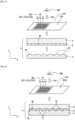
- FIG. 1 and 2 schematically represent the structure of an optical device 2 according to a particular embodiment of the invention.
- the optical device 2 comprises a textured layer 4, a support 6 and a holographic layer 8.
- the optical device 2 is made from a lamination of the textured layer 4 with the support 6 so that the holographic layer 8 is interposed between the textured layer 4 and the support 6.
- figure 1 represents the intrinsic constituent elements of the optical device 2 before the lamination step as well as the intrinsic holographic image IG1 formed intrinsically by the holographic layer 8 before lamination.
- figure 2 represents the optical device 2 formed following the lamination, as well as a personalized holographic image (or final image) IG1a produced by the optical device 2 following the deformation by lamination of the holographic layer 6.
- the textured layer 4 comprises a first surface 4a, namely the upper face in this example, this first surface 4a presenting first macro-textures denoted 10.
- These first macro-textures 10 are reliefs, present on the surface of the textured layer 4, the shapes and dimensions of which can be adapted as appropriate.
- these first macro-textures 10 are intended to deform the holographic layer 8 by lamination in order to create in the latter second macro-textures 11 which constitute a texturing in conformity with or complementary to the first macro-textures 10.
- first macro-textures 10 of textured layer 4 can form a particular pattern (relief pattern) intended to be transferred to holographic layer 8 as described below.
- the first macro-texturings 10 have for example a height of between 1 ⁇ m and 100 ⁇ m.
- the configuration in number, size, shape, etc. of the first macro-textures 10 can be adapted by those skilled in the art according to the desired visual effect.
- the first macro-textures 10 are uniform or regular, here semi-cylindrical or semi-spherical reliefs, which can be arranged periodically, as described later.
- the first macro-textures 10 are irregular or random macro-textures.
- the surface 4a of the textured layer 4 is for example an unmachined surface or one that has not undergone any particular treatment in order to guarantee it an irregular or rough surface condition.
- the first macro-textures 10 can be formed in various ways, for example by laser (using a CO 2 laser or other) or by a thermo-compression molding technique (as described below with reference to the figure 12 ). It is thus possible to form the first macrotextures 10 by laser thermal reflux or by laser ablation (ablation by means of ultra-short laser pulses).
- the holographic layer 8, placed between the textured layer 4 and the support 6, comprises a diffractive network forming by holographic effect an arrangement 15 of pixels 16 in a color base BC of at least two distinct colors ( figures 1-2 ).
- this diffractive grating may itself be formed by a plurality of diffractive gratings.
- This arrangement 15 of pixels 16 intrinsically forms, before lamination of the textured layer 4 with the support 6, the intrinsic holographic image IG1 ( figure 1 ). The lamination leads to the personalization of the arrangement 15 of pixels 16 which then forms the personalized holographic image IG1a ( figure 2 ).
- the color base BC is composed of 3 distinct colors CL1, CL2 and CL3 (for example a red-green-blue base), other examples of color bases BC with a plurality of colors distinct being possible.
- the holographic layer 8 comprises for example a metallic holographic structure configured to form by holographic effect an arrangement 15 of color pixels 16 in the color base BC.
- This holographic structure intrinsically produces the arrangement 15 of pixels 16 in the form of a holographic image IG1 by diffraction, refraction and/or reflection of incident light LG1.
- the configuration in size, shape, dimensions, etc. of the arrangement 15 can be adapted on a case-by-case basis by those skilled in the art.
- the shapes and dimensions of the pixels 16 as well as the spatial arrangement of the pixels 16 may vary depending on the case.
- the principle of the hologram is well known to those skilled in the art. Some items are listed below for reference. Examples of embodiments of holographic structures are described for example in the document EP 2 567 270 B1 .
- the diffraction occurring in a hologram is a reflection phenomenon with interferences, as is well known to those skilled in the art.
- diffraction at the level of a holographic diffractive grating therefore constitutes a particular case of the phenomenon of reflection at the interface between two materials. In other words, it can be considered that if the optically active layer 8 is holographic, it is both reflective and diffractive.
- the optical layer 8 is characterized by optical properties (in particular diffraction) which define the way in which an incident light LG1 interacts with the holographic layer 8 in particular by diffracting to produce a visual effect, as described above. -After.
- the holographic layer 8 comprises, for example, reliefs (or structures in relief) and a metal sub-layer with a high refractive index which covers these reliefs and which has a refractive index greater than the refractive index of the landforms.
- These reliefs include protruding portions (also called “mounts”) separated by recesses (also called “valleys”), so as to define three-dimensional information of a holographic image.
- the high refractive index metal underlayer can comprise at least one of the following materials: aluminum, silver, copper, zinc sulphide, titanium oxide, or a combination of at least two of these materials.
- the reliefs of the diffractive grating of the holographic layer 8 can be formed, for example, by embossing a layer of stamping varnish in a known manner for producing diffractive structures.
- the stamped surface of the reliefs thus has the form of a periodic diffractive grating whose depth and period can be respectively of the order of a hundred to a few hundred nanometers for example.
- the support 6 can be arbitrary. It may be a support layer, for example, making it possible to ensure good mechanical strength of the assembly.
- the diffractive grating of the holographic layer 8 is configured intrinsically (before the lamination of the constituent elements of the optical device 2) to form an arrangement 15 of pixels 16.
- the first surface 4a of the textured layer 4 is assembled by lamination with the support 6 so that the holographic layer 8, placed between the textured layer 4 and the support 6, is deformed by the first macro-textures 10 to present (or understand, or adopt) second macro-textures 11 conforming (or complementary) to the first macro-textures 10.
- the second macro-textures 11 of the holographic layer 8 are formed in correspondence with the first macro-textures 10 of the layer textured 4.
- lamination we mean in this document a mechanical process consisting in fixing together at least two layers by applying to these layers a mechanical pressure for an appropriate period, with or without the addition of heat, so that the layers involved are assembled at pressure and temperature such that the materials which constitute them reach their Vicat softening point and interpenetrate locally to give substantially coherent laminated assemblies.
- the lamination of the first surface 4a of the textured layer 4 with the support 6 involves a pressing action (or pressure), and possibly a heating (hot lamination), which causes a transfer of texturing (or transfer of relief ) from the textured layer 4 to the holographic layer 8 positioned opposite.
- the holographic layer 8 is deformed by a transfer of the macro-textures 10 of the layer textured 4 towards the holographic layer 8.
- the second macro-textures 11 are generated in the holographic layer 8 in accordance with the first macro-textures 10.
- the second macro-textures 11 according to which the holographic layer 8 during lamination are complementary, or substantially complementary (if possible imperfections in the transfer process are taken into account), to the first macro-textures 10 of the textured layer 4.
- the pattern according to which are formed the second macro-textures 11 is complementary to the pattern of the first macro-textures 10.
- the patterns of the first and second macro-textures 10, 11 respectively define the spatial arrangement of these macro-textures.
- the deformation by lamination of the diffractive network of the holographic layer 8 leads to a personalization (or modification) of the visual appearance of the holographic layer 8, that is to say of the arrangement 15 of pixels 16 intrinsically forming the intrinsic holographic image IG1, so as to obtain a personalized visual appearance of the arrangement 15 of pixels 16 which then takes the form of a personalized holographic image IG1a which is a function of the second macro-textures 11 formed in the holographic layer 8. Otherwise said, the holographic image IG1a thus obtained is formed by the holographic layer 8 which has been deformed by lamination to adopt the second macro-textures 11.
- the holographic layer 8 is laminated directly against the textured layer 4, although variants are possible in which one or more intermediate layers are present at the interface between the holographic layer 8 and the textured layer 4.
- the holographic layer 8 is substantially flat before the lamination (it extends in a plane).
- the holographic layer 8 follows the orientation of the support 6 before lamination insofar as the holographic layer 8 is placed on it.
- the holographic layer 8 can for example be formed (deposited, printed, etc.) on the support 6 before carrying out the lamination with the textured layer 4.
- the texturing of the support 6 is thus constrained by the adhesion of the holographic layer 8 on the support 6 depending on the forming process (printing process for example) used.
- the support 6 comprises a surface (or face) 6a on which the holographic layer 8 is formed before the lamination with the textured layer 4, this surface 6a possibly being smooth or having a slight random roughness in order to facilitate the formation of the holographic layer 8 (manipulation of the support and, if necessary, ink adhesion).
- the holographic layer 8 is for example deposited and bonded by a hot plating process on the support 6.
- the surface 6a of the support 8 has for example a roughness lower on average than 5 ⁇ m in amplitude before the lamination with the textured layer 4a.
- FIG. 3 schematically represents the way in which the diffractive network of the holographic layer 8 can be modified by the process of lamination of the textured layer 4 with the support 6. It is assumed for example that the holographic layer 8 intrinsically comprises (before lamination) a uniform diffractive structure without any particular reason. Under the effect of the lamination, the holographic layer 8 is deformed so that its diffractive network adopts at least one particular pattern, namely that of the second macro-textures 11a or 11b for example in the zones 8a and 8b respectively.
- the optical device 2 can be configured so that the holographic layer 8 comprises a plurality of textured regions, for example the textured regions 8b and 8c ( picture 3 ), these regions comprising second different macrotextures 11 .
- the optical device 2 can also be configured so that the holographic layer 8 includes at least one non-textured region 8a ( picture 3 ), i.e. a region devoid of second macrotextures 11.
- the first and second macro-textures 10, 11 have a height of between 1 ⁇ m and 100 ⁇ m.
- the pattern of the second macro-textures 11 formed during the deformation by lamination in the holographic layer 8 can be of various natures, includes semi-cylindrical or elliptical reliefs.
- the pattern of the second macro-textures 11 can also comprise any combination of the pattern configurations above.
- the textured layer 4 has a glass transition temperature greater than or equal to that of the support 6.
- the glass transition temperature is the temperature at which the material considered becomes viscous.
- the textured layer 4 is harder than the support 6, which makes it possible to guarantee good adhesion of the entire structure during lamination.
- the textured layer 4 and the support 6 are formed from the same material or from the same set of materials.
- the textured layer 4 and the support 6 have the same ability to adhere and can therefore fuse and adhere well with each other during lamination, which makes it possible to guarantee good mechanical properties of the structure. It is thus more difficult to subsequently separate the constituent elements of the optical device 2, which makes the latter more robust to falsifications.
- the textured layer 4 and the support 6 can for example both be formed from a material, or set of materials, based on a polymer. They can for example be made of plastic material (polycarbonate, polyethylene, etc.).
- the textured layer 4 can merge with the support 6 in one or more regions where the holographic layer 8 is not present at the interface between the textured layer 4 and the support 6.
- openings can be made in the holographic layer 8 or, more generally, at least one contact region is made so that the textured layer 4 is in direct contact with the support 6 (so that there is no does not have the optically active layer 8 at the interface in this region).
- the phenomenon of fusion of the textured layer 4 with the support 6 then leads to the creation of adhesion bridges fixing the textured layer 4 to the support 6 so as to trap the holographic layer 8 within the structure, which makes it possible to improve even more the good mechanical properties of the whole.
- the deformations generated by the lamination can cause modifications of the optical properties (diffraction or reflection) of the holographic layer 8.
- the holographic layer 8 is characterized by optical properties of reflection or diffraction which are a function of the second macro-textures 11 caused by the first macro-textures 10.
- These modifications of the optical properties in turn generate personalized visual effects IG1a, which are difficult to reproduce, and which can be authenticated using any appropriate optical inspection technique.
- the complexity of the visual effects IG1a can be controlled by adapting the pattern of the first macro-textures 10, and therefore the pattern of the second macro-textures 11 which are spatially arranged in accordance with (or in a complementary manner) to the first macro-textures 10.
- the effects visuals IG1 produced by the optical device 10 can in particular be uniform or non-uniform, or respect a particular pattern imposed by the spatial arrangement of the second macro-textures 11.
- the formation of the second macro-textures 11 in the optically active layer 8 leads to a change in the optical properties of diffraction of the optical active layer 8 after lamination compared to the optically active layer 8 intrinsic (before lamination).
- This change can result in a change in intensity of an incident light LG1 diffracted by the optically active layer 8 as a function of an angle of incidence of the incident light LG1 with respect to said holographic layer 8, or again by a change in color (or tint) as a function of the angle of incidence of the incident light LG1.
- the support 6 is composed of a material (or of a set of materials) at least partially transparent to light in the spectrum of visible wavelengths, which allows the exposure (or illumination ) of the holographic layer 8 to the incident light LG1 from the upper face of the optical device 2 as well as the observation (top view as illustrated in figure 2 ) of the personalized visual effect IG1a produced in response by the holographic layer 8.
- the textured layer 4 can be opaque or transparent depending on the case. In the case where the textured layer 4 is also at least partially transparent to light in the visible wavelength spectrum, an observer can then view the personalized visual effect IG1a produced by the holographic layer 8 from both sides ( upper and lower) of the optical device 2.
- the textured layer 4 is composed of a material (or of a set of materials) transparent at least partially to light in the spectrum of visible wavelengths, which allows the exposure of the holographic layer 8 to incident light from the underside of the optical device 2 as well as the observation (view from below) of the personalized visual effect IG1a produced in response by the holographic layer 8.
- the support 6 can be opaque or transparent depending on the case. As indicated above, when the support 6 and the textured layer 4 are transparent, it is possible to illuminate and view the holographic layer 8 from both sides of the optical device 2.
- the personalized visual rendering IG1a thus obtained then forms a holographic image when the optical device 2 is exposed to incident light (in the visible wavelength spectrum for example).
- incident light in the visible wavelength spectrum for example.
- An optical inspection can be performed by an OB observer (with the naked eye or by means of a viewing device) or by means of an optical inspection device configured to inspect (automatically or not) the custom visual effect IG1a produced by the optical device 2 under illumination of an incident light.
- FIG 4 represents an example of a personalized holographic image IG1a produced by an optical device 2 under illumination of an incident light, for example in the visible wavelength spectrum, as previously described. More precisely, this personalized image IG1a emanates from the holographic layer 8 which is configured to form the arrangement 15 of pixels 16 and which has second macro-textures 11 to personalize this arrangement 15. In this example, the second macro-textures 11 thus form in the final image IG1a a pattern of a predetermined geometric shape (a grid of curvilinear lines in this example).
- the diffractive network can extend intrinsically (before lamination) in a single plane (to form for example a thin 2-dimensional layer).
- the formation of the second macro-textures 11 then confers a particular orientation in 3 dimensions (non-planar) to the diffractive grating.
- the lamination has the effect that the diffractive grating no longer extends in a single plane but presents orientations in 3 dimensions (for example with protruding parts, valleys, recesses, etc.).
- the orientation of the diffraction can be distributed in a personalized way, for example around the axis perpendicular to the axis of the diffraction grating.
- the lamination performed makes it possible to totally or substantially retain the intrinsic structure of the diffractive grating.
- the spatial orientation of the holographic layer 8 (which contains the diffractive grating) is modified or personalized while the intrinsic structure of the diffractive grating is preserved.
- the diffractive grating can keep in particular the same period, but with a different orientation in space.
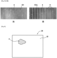
- THE figures 5A and 5B are top views of a region of the holographic layer 8 respectively before lamination ( figure 5A ), and after lamination ( figure 5B ) of the textured layer 4 with the support, as previously described.
- second macro-textures 11 are formed in the holographic layer 8 which causes the introduction of a striped pattern in the final holographic image IG1a.
- the optical device 2 as previously described is suitable for being integrated (or positioned) in or on a document to serve as a security device.
- a document comprising the optical device 2 thus constitutes a secure document insofar as the optical device 2 can be authenticated from a visual or optical analysis of the personalized holographic image IG1a produced by the holographic layer 8 under illumination of an incident light
- FIG. 6 schematically represents a secure document 20 comprising a document body 22 in which is incorporated the optical device 2 serving as a security device according to a particular embodiment.
- the secure document 20 is for example a card (smart card, badge, or other).
- the shape and configuration of the optical device 2 as well as of the document 20 itself can be adapted by those skilled in the art according to the case of use.
- the optical device of the invention makes it possible to form a high quality and secure personalized holographic image, and this from a holographic layer which is configured to form an arrangement of pixels and which is further deformed by lamination with a textured layer. to customize the visual appearance of the pixel arrangement.
- the diffractive grating of the holographic layer can extend intrinsically (before lamination) in a single plane (in the form for example of a thin 2D layer).
- the addition of the macro-texturing according to the invention gives the diffractive grating an orientation along a third dimension (nonplanar). Thanks to this macro-texturing, it is therefore possible to distribute the orientation of the diffraction around the axis perpendicular to the diffraction grating, and thus create various patterns in the arrangement of pixels to obtain a personalized holographic image.
- the optical device of the invention is difficult to reproduce or falsify and can be authenticated reliably and securely. Authentication of the optical device can be carried out by analyzing the pattern of the macro-textures formed in the holographic layer and by checking the position or the alignment of this pattern with respect to the arrangement of pixels.
- the invention finds particular application in particular in security devices able to be associated with a document or any other object with a view to securing it (for example identity documents, official documents or others).
- security devices able to be associated with a document or any other object with a view to securing it (for example identity documents, official documents or others).
- the invention makes it possible in particular to form personalized security devices at low cost and making it possible to effectively secure a document or the like.
- the holographic layer 8 is integrated within the structure of the optical device 2, between the textured layer 4 and the support 6 which are laminated together and which are preferentially fused together, which makes it difficult for the holographic layer 8 by a counterfeiter without damaging or destroying the optical device 2.
- the formation of the second macro-textures 11 by lamination in the optical layer 8 also makes it possible to obtain a wide range of viewing angles in which an observer OB can view the personalized holographic image IG1a produced by the optical device 2, as described in more detail below in specific examples.
- FIG. 7A represents the holographic layer 8 before the lamination of the textured layer 4 with the support 6, while the figures 7B and 7C represent the holographic layer 8 in which second macro-textures 11 are formed by lamination according to embodiments of the invention.
- the second macro-textures 11 formed by lamination in the holographic layer 8 are of semi-cylindrical shape ( figure 7B ) or elliptical ( Fig. 7C ) and extend along a first orientation (or first direction) denoted O1 in the plane (xy) of the holographic layer 8.
- the second semi-cylindrical or elliptical macrotextures 11 make it possible to orient the incident light LG1 diffracted by the diffraction gratings homogeneously in space, thus improving the quality of the holographic image viewable by an observer from the 16 color pixels.
- the holographic layer 8 is further configured to form in the form of a hologram an arrangement 15 of pixels 16.
- the pixels 16 are each formed by a corresponding portion (or section) of the diffractive grating of the holographic layer 8.
- These corresponding portions of the diffractive grating, and more generally the diffractive grating itself, are structured in (comprise) diffractive lines LD extending along a second orientation (or first direction) O2 perpendicular to the first orientation O1 in the plane of the holographic layer.
- diffractive lines is meant here diffraction lines according to which the diffractive grating of the holographic layer 8 is structured.
- the diffractive lines LN are rectilinear, although variants are possible with curvilinear diffraction lines.
- the way the pixels 16 are arranged may vary depending on the case.
- the pixels 16 of the diffractive grating of the holographic layer 8 are at least partly arranged so as to form rows of pixels denoted LN, each of these rows being in a single color CL1-CL3 among the base BC colors.
- these lines LN of pixels are parallel and oriented according to the orientation O2.
- these lines LN of pixels extend perpendicularly (or substantially perpendicularly) to the orientation O1 of the second macro-textures 11 of semi-cylindrical or elliptical shape ( Figures 7B-7C ).
- the lines LN of pixels and the sections of the diffraction grating (that is to say the diffractive lines LD) constituting these lines LN of pixels are perpendicular to the second semi-cylindrical or elliptical macrotextures 11 .
- the holographic layer 8 before lamination is devoid of macro-texturing.
- the holographic layer 8 therefore forms by holographic effect the lines LN of color pixels which are not personalized by means of macro-texturing.
- the non-personalized pixel lines LN thus extend in 2 dimensions, namely in the (or substantially in) plane of the holographic layer 8.
- An incident ray LG1a is thus diffracted by the diffractive grating of the layer holographic 8 so as to form a diffracted ray LG1b.
- the range of illumination angles ⁇ 1, with respect to the normal to the plane of the holographic layer 8, in which the holographic layer 8 must be illuminated by the incident light LG1 to form a holographic image is by nature restricted.
- the range of viewing angles ⁇ 2, relative to the normal to the plane of the holographic layer 8, in which the holographic image can be viewed for an observer is also by nature restricted.
- the formation by lamination of the second macro-textures 11 in the holographic layer 8 makes it possible to enlarge the range of illumination angle ⁇ 1, with respect to the normal to the plane of the holographic layer 8, in which the holographic layer 8 must be illuminated by the incident light LG1 to form a holographic image, namely the personalized image IG1a.
- this makes it possible to enlarge the range of viewing angles ⁇ 2, relative to the normal to the plane of the holographic layer 8, in which the personalized holographic image IG1a can be viewed.
- the perpendicular configuration of the lines LN of pixels (and therefore of the diffractive lines LD) with respect to the second macro-textures 11 makes it possible to obtain a good quality holographic image insofar as this makes it possible to guarantee a homogeneous diffraction of the incident light LG1 on the lines LN of pixels and makes it possible to prevent the diffraction phenomenon from being suppressed or limited in certain cases.
- the deformations generated by the texturing can thus be the same (or substantially the same) on each pixel line LN. If, on the contrary, the second macro-textures 11 were parallel to the lines LN of pixels, certain lines of color could always be on a crest of the second macro-textures 11 and others always in a recess. The orientation of the diffraction would then be different from one LN pixel line to another, which would degrade the quality of the final holographic image.
- the lines LN of pixels are arranged periodically in the plane of the holographic layer 8. This arrangement makes it possible to obtain a homogeneous visual effect by diffraction of an incident light by the diffractive grating of the layer holographic 8.
- the LN rows of pixels are arranged by group GP of LN rows of pixels in each color among the base of colors BC, each group GP comprising one (or being formed of a) plurality of LN rows of pixels in the same color from the colors CL1-CL3 of the color base BC.
- the rows LN of pixels are further arranged periodically in each group GP. It is thus possible to spatially arrange the groups GP according to a periodic alternation in the different colors of the base BC of colors used. This particular arrangement makes it possible to obtain good image quality.
- the lines of pixels are spatially arranged in each group GP according to a pitch D1 separating each pair of lines LN of adjacent pixels, such that P ⁇ 100 ⁇ m ( Figures 7A-7C ).
- the lines LN of pixels are spatially arranged in each group GP so that each pair of two adjacent lines LN of pixels are spaced from each other by a pitch P, where P ⁇ 100 ⁇ m.
- the distance D1 separating the lines LN of neighboring pixels is thus less than the resolving power of the human eye, which makes it possible to obtain a good quality holographic image insofar as an observer is not able to distinguish or differentiate individually LN rows of pixels from each other.
- the pixels 16 of the arrangement 15 formed by the holographic layer 8 each comprise a plurality of sub-pixels of distinct colors (or respective colors) in the base BC of colors (CL1-CL3 in this example ).
- THE figures 8-9 thus represent a particular embodiment in which the pixels 16 of the arrangement 15 each comprise a plurality of sub-pixels 18 of distinct color in the base BC of at least two distinct colors (namely CL1-CL3 in this example) .
- each sub-pixel 18 is formed by a respective portion (or section) of diffractive grating, of the holographic layer 8, configured to generate by diffraction a corresponding color of said sub-pixel.
- each pixel 16 of the arrangement 15 of pixels forms an identical pattern of color sub-pixels in the base BC of colors (for example a red-green-blue pattern according to a predetermined spatial arrangement).
- This arrangement 15 of pixels 16 is further personalized by means of perforations as described below.
- the optical device 2 further comprises a personalization layer 40 positioned facing the holographic layer 8.
- the personalization layer 40 is an additional layer positioned under the textured layer 4, so that the textured layer 4 is interposed between the holographic layer 8 and the personalization layer 40.
- the personalization layer and the textured layer 4 can for example form one and the same layer, so that no other additional layer is required for this purpose.
- the holographic layer 8 comprises perforations (or micro-perforations) 30 formed by laser radiation LS1. These perforations 30 reveal locally through the holographic layer 8 areas of colorimetric nuance 32, in the sub-pixels 18, caused by underlying regions 31 of the personalization layer 40. These underlying regions 31, located in next to the perforations 30, personalize the arrangement 15 of pixels and thus make it possible to form the personalized holographic image (or final image) IG1a from the arrangement 15 of pixels combined with the colorimetric shade zones 32.
- the perforations 30 constitute regions in which the holographic layer 8 is destroyed (or removed) locally by the perforation effect of the laser. In addition to locally destroying the diffractive structure of the holographic layer 8, these perforations 30 locally reveal through the holographic structure areas of colorimetric nuance 32 caused by the underlying regions 31 positioned in correspondence in the personalization layer 40.
- the textured layer 4 and the support 6 are transparent 4 vis-à-vis at least the visible wavelength spectrum so that a user can visualize, in the form colorimetric shade zones 32, the underlying regions 31 of the personalization layer 40.
- the perforations 40 are through perforations which extend through the thickness of the holographic layer 8 so as to reveal the underlying regions 31 of the personalization layer 34 at the level of the arrangement 15 of pixels 16. Otherwise said, by making these perforations 40 with the laser in the thickness of the holographic layer 8, it is possible to discover underlying regions 31 of the personalization layer 40 so as to produce the colorimetric shade zones 32 in all or parts of the underside - 18 pixels.
- the colorimetric shade areas 32 are areas of color shade (or gray level) with respect to the respective colors of the sub-pixels 18. The nature and appearance of these colorimetric shade areas 32 may vary depending on the configuration of the personalization layer 40 used. As described below, the personalization layer 40 can be opaque, or transparent, or even be sensitive to ultraviolet rays, which impacts differently the colorimetric influence of the zones of colorimetric nuance 32 in the final image IG1b.
- the personalization layer 40 is opaque vis-à-vis at least the visible wavelength spectrum.
- the areas of colorimetric nuance 32 caused by the underlying regions 31 of the personalization layer 40 are dark (or opaque) areas formed in the sub-pixels 18.
- a personalized holographic image IG1a is thus formed by the arrangement 15 of pixels combined with the dark areas 32.
- the personalization layer 40 comprises an ink sensitive to ultraviolet rays, so that the personalized holographic image IG1a is visible when the optical device 2 (and more particularly the holographic layer 8) is exposed to ultraviolet rays. Under illumination of incident light LG1 in the ultraviolet, the ink produces light in the visible wavelength spectrum, thus causing the formation in the sub-pixels 18 of colorimetric shades 32.
- the personalization layer 40 is transparent with respect to at least the visible wavelength spectrum.
- the areas of colorimetric shading 32 caused by the underlying regions 31 of the personalization layer 40 are light (or bright) areas in the sub-pixels 18 when incident light LG1 in the wavelength spectrum of the visible is projected through the perforations 32.
- the perforations 40 may have various shapes and dimensions which may vary depending on the case. More particularly, the perforations 40 are arranged so as to select the color of the pixels 16 by modifying the colorimetric contribution of the sub-pixels 18 relative to each other in at least part of the pixels 16 formed by the holographic layer 8, so to reveal the custom image IG1a from the arrangement 15 of pixels combined 32 color swatch areas.
- shades of colors are thus generated in the pixels 16 by modifying the colorimetric contribution of certain sub-pixels 18, relative to each other, in the visual rendering of the final image IG1a.
- the colorimetric nuance zones 32 make it possible in particular to modulate the passage of light so that, for at least part of the pixels 16, a sub-pixel 18 or more has an increased or decreased colorimetric contribution (or weight) compared to to that of at least one other sub-pixel 18 close to the pixel concerned.
- the holographic effect can thus be eliminated, or reduced, in the regions perforated of the holographic layer 8, which reduces (or even completely eliminates) the relative color contribution of the sub-pixels 18 which are perforated at least in part with respect to at least one other sub-pixel 18 neighboring the pixels 16 concerned.
- the personalized image IG1a thus created is a color image resulting from a selective modulation of the colorimetric contributions of sub-pixels 18 of color. It should be noted, however, that a personalized image IG1a in gray levels can be produced in the same way by adapting the colors of the sub-pixels 18 accordingly.
- the laser radiation LS1 used to form the perforations 30 in the holographic layer 8 is preferably in a spectrum of wavelengths different from the spectrum of wavelengths of the visible. To do this, it is possible for example to use a YAG laser (for example at a wavelength of 1064 nm), a blue laser, a UV laser, etc. It is also possible to apply, for example, a pulse frequency of between 1 kHz and 100 kHz, although other configurations can be envisaged. It is up to the person skilled in the art to choose the configuration of the laser radiation LS1 according to the specific case.
- the laser radiation LS1 is characterized by a spectrum of wavelengths which is absorbed at least partially by the holographic layer 8.
- the materials of the holographic layer 8 are therefore chosen accordingly.
- the materials forming the holographic layer 8 are selected so that they do not absorb light in the visible. In this way, it is possible to create perforations 30 by means of laser radiation LS1 emitting outside the visible spectrum and to generate a personalized image IG1a which is visible to the human eye by holographic effect.
- the holographic layer 8 may for example be made of transparent polycarbonate, PVC, transparent glue, etc.
- the perforations 30 are formed by projecting the laser radiation LS1 onto the holographic layer 8 at a power less than or equal to a threshold value beyond which a "blistering" effect (loss of adhesion between the layers ) is likely to occur, which ensures that no air bubbles are generated that could damage the structure.
- This laser power threshold value is however variable and depends on each case of use (depends in particular on the types of hologram and the characteristics of the laser used).
- This threshold value can be determined by a person skilled in the art, in particular by means of an appropriate experimental design which makes it possible to determine the laser power beyond which the laser causes destruction of the structure (appearance of bubbles).
- the addition of the perforations 30 thus makes it possible to create shades of color so as to form a secure and good quality IG1a color image, thanks to the interaction between the zones colorimetric shade 32 and the arrangement 15 of pixels formed by the holographic layer 8.
- the pixels 16 without the formation of these colorimetric shade zones 32 by perforation as described above to judiciously orient or select the passage of light incident LG1, the pixels 16 only form a blank arrangement of pixels insofar as this set is devoid of the information characterizing the desired color image.
- the perforations 40 which are configured, depending on the arrangement of sub-pixels 18 chosen, to personalize the visual appearance of the pixels 16 and thus reveal the final color image IG1a.
- FIG. 10-12 A method of manufacturing an optical device 2 ( figures 1-9 ) as previously presented is described below with reference to the figures 10-12 , according to particular embodiments. In general, the different embodiments and implementation details described above concerning the optical device 2 with reference to the figures 1-9 can be applied analogously to the manufacturing method of said optical device 2.
- a textured layer 4 as previously described is formed, this layer comprising in particular a first surface 4a having first macro-textures 10.
- first macro-textures 10 are possible at the level of the surface 4a of the textured layer 4.
- the first macro-textures 10 of the textured layer are for example formed by laser or by a thermo-compression molding technique.
- the first surface 4a of the textured layer 4 is positioned facing a support 6 comprising on the surface (on its lower face 6a in this example) a holographic layer 8 inserted between the textured layer 4 and the support 6.
- the holographic layer 8 is for example formed for example by printing or depositing on the surface 6a of the support 6 before the next lamination step S6.
- the first surface 4a of the textured layer 4 is laminated on the support 6, thus causing a deformation by the first macro-textures 10 of the holographic layer 8 placed between the textured layer 4 and the support 6, so that the layer holographic 8 comprises second macro-textures 11 conforming to the first macro-textures 10, as already described.
- the second macro-textures 11 thus formed are therefore complementary with the first macro-textures 10 of the textured layer 4.
- the optical device 2 resulting from steps S2-S6 can possibly be integrated or incorporated in or on a document 20, and more particularly in or on the body 22 of said document, so that the optical device 2 serves as a security device allowing to authenticate the document considered (then called “secure document”) from the personalized holographic image IG1a thus formed.
- a formation step S7 is also carried out after the lamination step S6, and before the optional integration step S8. More particularly, laser radiation LS1 is projected (S7) onto the optical device 2 as already described in order to form perforations 30 ( figures 8-9 ) in the holographic layer 8 so as to form areas of colorimetric shade 32 in the sub-pixels 18. These areas of colorimetric shade 32 (dark, opaque or transparent) are caused by underlying regions 31, of the layer of personalization 40, located opposite the perforations 30, so as to form a personalized holographic image IG1a from the arrangement 15 of pixels combined with the colorimetric shade areas 32.
- FIG. 12 it is for example possible to use a system of rollers 62 comprising at least one textured roller 64 configured to apply by lamination a textured layer 4 on a free face of the holographic layer 8 so as to form the above-described laminated assembly.
Landscapes
- Engineering & Computer Science (AREA)
- Manufacturing & Machinery (AREA)
- Physics & Mathematics (AREA)
- Optics & Photonics (AREA)
- Health & Medical Sciences (AREA)
- Electromagnetism (AREA)
- General Health & Medical Sciences (AREA)
- Toxicology (AREA)
- General Physics & Mathematics (AREA)
- Holo Graphy (AREA)
- Diffracting Gratings Or Hologram Optical Elements (AREA)
Abstract
Description
- L'invention se rapporte au domaine des images holographiques et porte notamment sur des dispositifs optiques configurées pour former une image holographique à partir d'un arrangement de pixels. L'invention vise notamment de tels dispositifs optiques aptes à être intégrés dans un document ou un quelconque autre support pour servir de dispositif de sécurité.
- Le marché de l'identité requiert aujourd'hui des documents d'identité (dits aussi documents identitaires) de plus en plus sécurisés. Ces documents doivent être facilement authentifiables et difficiles à contrefaire (si possible infalsifiables). Ce marché concerne des documents très diverses, tels que cartes d'identité, passeports, badges d'accès, permis de conduire etc., qui peuvent se présenter sous différents formats (cartes, livrets...).
- Divers types de documents sécurisés comportant des images ont ainsi été développés au cours du temps, notamment pour identifier de manière sécurisée des personnes. De plus en plus de passeports, cartes d'identité ou autres documents officiels comportent aujourd'hui des éléments de sécurité qui permettent d'authentifier le document et de limiter les risques de fraudes, falsification ou contrefaçon. Les documents identitaires électroniques comportant une carte à puce, tels que les passeports électroniques par exemple, connaissent ainsi un essor important ces dernières années.
- Diverses techniques d'impression ont été développées au fil du temps pour réaliser des impressions d'image, en noir et blanc ou en couleur. La réalisation en particulier de documents identitaires tels que ceux précités nécessitent de réaliser des images de façon sécurisée afin de limiter les risques de falsification par des individus malveillants. La fabrication de tels documents, au niveau en particulier de l'image d'identité du porteur, nécessite d'être suffisamment complexe pour rendre difficile la reproduction ou falsification par un individu non autorisé.
- Une autre technique connue de formation d'image concerne les hologrammes, ce type d'image pouvant notamment être utilisé pour sécuriser un document ou autre. En inspectant par exemple une image holographique sous une certaine illumination, il est possible de vérifier l'authenticité de l'image et ainsi déterminer si l'objet auquel elle est associée est authentique ou non.
- Les dispositifs optiques connus à ce jour, et plus particulièrement ceux configurés pour former des images holographiques, ne sont toutefois pas toujours satisfaisants. Un besoin existe pour former de façon sécurisée des images personnalisées de haute qualité (en couleurs ou en noir et blanc), notamment pour servir de dispositifs de sécurité dans des documents (documents identitaires, documents officiels, etc.) ou tout autre objet nécessitant d'être sécurisé. Un besoin existe en particulier pour permettre une personnalisation flexible et sécurisée d'images couleurs, ou en noir et blanc (en niveaux de gris), de sorte que l'image ainsi produite soit difficile à falsifier ou à reproduire et puisse être authentifiée de façon fiable et sécurisée.
- Un besoin existe en particulier pour une technique de formation d'image offrant un niveau élevé de sécurité et de flexibilité de fabrication ainsi qu'un bon niveau de qualité d'image, en termes notamment de luminosité de l'image et de gamut de couleur, par exemple lorsque des zones d'image doivent présenter un niveau hautement saturé dans une couleur donnée.
- Par ailleurs, pour bien séparer les longueurs d'onde, les réseaux diffractifs holographiques imposent généralement des angles d'illumination relativement faibles de la lumière incidente. De plus, l'angle de visualisation est généralement restreint pour visualiser l'image holographique avec de bonnes couleurs. Au-delà d'un certain angle d'observation, l'observateur ne voit plus correctement l'image holographique.
- En raison de la vision stéréoscopique des humains, il est généralement difficile pour un observateur de visualiser correctement une image holographique. En particulier il est difficile de trouver le bon angle d'illumination et le bon angle d'observation, d'autant plus en raison du fait que chaque œil de l'observateur visualise l'image suivant un plan légèrement différent. Si l'hologramme n'est pas illuminé et visualisé selon le bon couple d'angles (illumination, visualisation), l'observateur ne voit pas, ou mal, les couleurs de l'image holographique.
- Un besoin existe donc également pour des images holographiques de bonne qualité autorisant des plages d'angles d'illumination et d'angles d'observation plus importantes.
- A cet effet, la présente invention concerne un dispositif optique comprenant :
- une couche texturée comprenant une première surface présentant des premières macro-texturations; et
- un support comprenant en surface une couche holographique intercalée entre la couche texturée et le support, la couche holographique comprenant un réseau diffractif formant par effet holographique un arrangement de pixels dans une base d'au moins deux couleurs distinctes,
- Selon une caractéristique générale, les deuxièmes macro-texturations de la couche holographique sont de forme semi-cylindrique ou elliptique et s'étendent selon une première orientation dans le plan de la couche holographique,
- chaque pixel étant formé par une portion correspondante du réseau diffractif, ladite portion correspondante étant structurée en lignes diffractives s'étendant selon une deuxième orientation perpendiculaire à la première orientation dans le plan de la couche holographique.
- Le dispositif optique de l'invention permet de former une image holographique personnalisée de haute qualité et sécurisée, et ce à partir d'une couche holographique qui est configurée pour former un arrangement de pixels et qui est en outre déformée par lamination avec une couche texturée de sorte à personnaliser l'apparence visuelle de l'arrangement de pixels.
- Le réseau diffractif de la couche holographique peut s'étendre intrinsèquement (avant la lamination) dans un seul plan (sous la forme par exemple d'une couche mince 2D). La formation des deuxièmes macro-texturations confère au réseau diffractif une orientation modifiée suivant une troisième dimension (non plane). Grâce à cette macro-texturation, on peut donc répartir l'orientation de la diffraction autour de l'axe perpendiculaire au réseau de diffraction, et ainsi créer divers motifs dans l'arrangement de pixels pour obtenir une image holographique personnalisée.
- Le dispositif optique de l'invention est difficile à reproduire ou falsifier et peut être authentifié de façon fiable et sécurisée. L'authentification du dispositif optique peut être réalisée en analysant le motif des deuxièmes macro-texturations formées dans la couche holographique et en vérifiant la position ou l'alignement de ce motif par rapport à l'arrangement de pixels.
- Aussi, l'invention trouve une application particulière notamment dans les dispositifs de sécurité aptes à être associés à un document ou tout autre objet en vue de le sécuriser (par exemple des documents identitaires, documents officiels ou autres). L'invention permet en particulier de former des dispositifs de sécurité personnalisés à bas coût et permettant de sécuriser efficacement un document ou autre.
- La formation des deuxièmes macro-texturations par lamination dans la couche holographique permet également d'obtenir une plage importante d'angles d'observation dans laquelle un observateur peut visualiser l'image holographique personnalisée produite par le dispositif optique, comme décrit plus en détail ci-après dans des exemples particuliers.
- Selon un mode de réalisation particulier, les premières et deuxièmes macro-texturations présentent une hauteur comprise entre 1 µm et 100 µm.
- Selon un mode de réalisation particulier, les pixels du réseau diffractif sont au moins en partie arrangés de sorte à former des lignes de pixels chacune dans une couleur unique parmi la base d'au moins deux couleurs distinctes, les lignes de pixels s'étendant selon la deuxième orientation.
- Selon un mode de réalisation particulier, les lignes de pixels sont arrangées de façon périodique dans la couche holographique.
- Selon un mode de réalisation particulier, les lignes de pixels sont arrangées par groupe de lignes de pixels dans chaque couleur parmi la base d'au moins deux couleurs distinctes, chaque groupe comprenant une pluralité de lignes de pixels dans une même couleur parmi ladite base d'au moins deux couleurs distinctes,
les lignes de pixels étant arrangées périodiquement dans chaque groupe. - Selon un mode de réalisation particulier, les lignes de pixels sont arrangées spatialement dans chaque dit groupe selon un pas séparant chaque paire de lignes de pixels adjacentes, tel que P ≤ 100 µm.
- Selon un mode de réalisation particulier, la couche texturée présente une température de transition vitreuse supérieure ou égale à celle du support.
- Selon un mode de réalisation particulier, la couche texturée et le support sont formés d'un même matériau ou d'un même ensemble de matériaux.
- Selon un mode de réalisation particulier, la couche holographique se caractérise par des propriétés optiques de diffraction qui sont fonction des deuxièmes macro-texturations formées par lamination selon un motif en relief imposé par les premières macro-texturations de la couche texturée.
- Selon un mode de réalisation particulier, les pixels dudit arrangement de pixels comportent chacun une pluralité de sous-pixels de couleurs distinctes dans la base d'au moins deux couleurs distinctes,
- le dispositif comprenant une couche de personnalisation positionnée en regard de la couche holographique,
- dans lequel la couche holographique comprend des perforations formées par un rayonnement laser, lesdites perforations révélant localement au travers de la couche holographique des zones de nuance colorimétrique dans les sous-pixels causées par des régions sous-jacentes, de la couche de personnalisation, situées en regard des perforations, de sorte à former une image holographique personnalisée à partir de l'arrangement de pixels combiné aux zones de nuance colorimétrique.
- Selon un mode de réalisation particulier, la couche de personnalisation est l'une parmi :
- la couche texturée ; et
- une couche positionnée en regard de la couche holographique de sorte que la couche texturée est intercalée entre la couche holographique et la couche de personnalisation.
- Selon un mode de réalisation particulier, ladite couche de personnalisation est opaque vis-à-vis au moins du spectre de longueurs d'onde du visible, les zones de nuance colorimétrique causées par les régions sous-jacentes de la couche de personnalisation étant des zones sombres dans les sous-pixels
- Selon un mode de réalisation particulier, chaque pixel dudit arrangement de pixels forme un motif identique de sous-pixels de couleur dans la base d'au moins deux couleurs.
- Selon un mode de réalisation particulier, la couche de personnalisation comporte une encre sensible aux ultraviolets, de sorte que l'image holographique personnalisée est visible lorsque le dispositif est exposé à des ultraviolets.
- Selon un mode de réalisation particulier, la couche de personnalisation est transparente vis-à-vis au moins du spectre de longueurs d'onde du visible, les zones de nuance colorimétrique causées par les régions sous-jacentes de la couche de personnalisation étant des zones claires dans les sous-pixels lorsqu'une lumière incidente dans le spectre du visible est projetée au travers des perforations.
- Corrélativement, la présente invention concerne un document sécurisé comprenant un corps de document et un dispositif optique tel que défini ci-avant et décrit ci-après dans des modes de réalisation particuliers. Le dispositif optique peut ainsi être intégré en tant que dispositif de sécurité dans ou sur le corps de document.
- La présente invention vise également un procédé de fabrication correspondant, à savoir un procédé pour fabriquer un dispositif optique tel que défini ci-avant et décrit ci-après dans des modes de réalisation particuliers. En particulier, l'invention prévoit un procédé de fabrication d'un dispositif optique, ledit procédé comprenant :
- formation d'une couche texturée comprenant une première surface présentant des premières macro-texturations; et
- positionnement de la première surface de la couche texturée en vis-à-vis d'un support comprenant en surface une couche holographique intercalée entre la couche texturée et le support,
- la couche holographique comprenant un réseau diffractif formant par effet holographique un arrangement de pixels dans une base d'au moins deux couleurs distinctes ; et
- lamination de la première surface de la couche texturée sur le support, causant une déformation par les premières macro-texturations de la couche holographique disposée entre la couche texturée et le support, de sorte à former dans la couche holographique des deuxièmes macro-texturations conformes auxdites premières macro-texturations, l'apparence visuelle de l'arrangement de pixels étant personnalisée par les deuxièmes macro-texturations.
- Selon une caractéristique générale, les deuxièmes macro-texturations de la couche holographique sont de forme semi-cylindrique ou elliptique et s'étendent selon une première orientation dans le plan de la couche holographique,
- chaque pixel étant formé par une portion correspondante du réseau diffractif, ladite portion correspondante étant structurée en lignes diffractives s'étendant selon une deuxième orientation perpendiculaire à la première orientation dans le plan de la couche holographique.
- A noter que les différents modes de réalisation mentionnés ci-avant (ainsi que ceux décrits ci-après) en relation avec le dispositif optique de l'invention ainsi que les avantages associés s'appliquent de façon analogue au procédé de fabrication de l'invention.
- Selon un mode de réalisation particulier, lors de la formation de la couche texturée, les premières macro-texturations de la couche texturée sont formées au laser ou par une technique de moulage par thermo-compression.
- L'invention concerne également un procédé de fabrication d'un document sécurisé tel que précédemment défini.
- D'autres caractéristiques et avantages de la présente invention ressortiront de la description faite ci-dessous, en référence aux dessins annexés qui en illustrent des exemples de réalisation dépourvus de tout caractère limitatif. Sur les figures:
- [
Fig. 1 ] Lafigure 1 représente schématiquement les éléments constitutifs d'un dispositif optique en cours de fabrication selon au moins un mode de réalisation de l'invention ; - [
Fig. 2 ] Lafigure 2 représente schématiquement la structure d'un dispositif optique selon au moins un mode de réalisation de l'invention ; - [
Fig. 3 ] Lafigure 3 représente schématiquement la structure de la couche holographique d'un dispositif optique selon au moins un mode de réalisation de l'invention ; - [
Fig. 4 ] Lafigure 4 représente un dispositif optique selon au moins un mode de réalisation de l'invention ; - [
Fig. 5A-5B ] Lesfigures 5A et 5B sont des vues de haut représentant une région de la couche holographique d'un dispositif optique respectivement avant et après lamination, selon des modes de réalisation de l'invention ; - [
Fig. 6 ] Lafigure 6 représente un document sécurisé comprenant un dispositif optique selon au moins un mode de réalisation de l'invention ; - [
Fig. 7A-7B-7C ] Lafigure 7A représente schématiquement la couche holographique d'un dispositif optique avant lamination selon un mode de réalisation de l'invention, et lesfigures 7B et 7C représentent schématiquement la couche holographique d'un dispositif optique après lamination selon des modes de réalisation de l'invention ; - [
Fig. 8 ] Lafigure 8 représente un dispositif optique de l'invention selon au moins un mode de réalisation de l'invention ; - [
Fig. 9 ] Lafigure 9 représente un dispositif optique de l'invention selon au moins un mode de réalisation de l'invention ; - [
Fig. 10 ] Lafigure 10 représente, sous forme d'un diagramme, les étapes d'un procédé de fabrication selon certains modes de réalisation de l'invention ; - [
Fig. 11 ] Lafigure 11 représente, sous forme d'un diagramme, les étapes d'un procédé de fabrication selon certains modes de réalisation de l'invention ; et - [
Fig. 12 ] Lafigure 12 représente schématiquement la formation d'une couche texturée lors d'un procédé de fabrication selon au moins un mode de réalisation de l'invention. - Comme déjà indiqué, l'invention concerne un dispositif optique configuré pour former de façon sécurisée une image holographique de haute qualité, pouvant éventuellement être authentifiée par un observateur ou une entité tierce. Pour ce faire, l'invention met en oeuvre une technique de transfert de texturation pour transférer par lamination des macro-texturations depuis une couche texturée vers une couche holographique, cette dernière comprenant un (ou au moins un) réseau diffractif configuré pour former par effet holographique un arrangement de pixels dans une base de couleurs. Ce transfert de texturation est réalisé en déformant la couche holographique par lamination avec la couche texturée de sorte à ce que la couche holographique forme ou adopte en surface des macro-texturations qui modifient ses propriétés optiques de diffraction, ce qui conduit à une personnalisation de l'arrangement de pixels, et donc de l'effet visuel (ou apparence visuelle) produit par la couche holographique.
- L'invention, selon ses différents modes de réalisation, met ainsi en oeuvre un dispositif optique comprenant : une couche texturée comprenant une première surface présentant des premières macro-texturations; et un support comprenant en surface une couche holographique intercalée entre la couche texturée et le support, la couche holographique comprenant un (ou au moins un) réseau diffractif formant par effet holographique un arrangement de pixels dans une base d'au moins deux couleurs distinctes. La première surface de la couche texturée est assemblée par lamination avec le support de sorte que la couche holographique, disposée entre la couche texturée et le support, est déformée par les premières macro-texturations pour comprendre des deuxièmes macro-texturations conformes auxdites premières macro-texturations, l'apparence visuelle de l'arrangement de pixels étant personnalisée par les deuxièmes macro-texturations.
- L'invention s'applique aussi bien à la formation d'images holographiques en couleurs que des images holographiques en noir et blanc, c'est-à-dire en niveaux de gris. Aussi, dans le présent document, la notion de couleur peut s'appliquer par extension aux niveaux de gris d'une image en noir et blanc.
- Dans ce document, la notion de « macro-texturation » désigne des reliefs formés en surface d'un matériau (par exemple en polycarbonate pour un document d'identité) par un procédé de formation approprié permettant de déformer la surface de ce matériau (par exemple, au moyen d'une technique de déformation au laser CO2, par lamination...), les propriétés de forme et de résistance mécanique des reliefs ainsi obtenus permettant un transfert de reliefs par lamination (quantifiable et ajustable) vers une autre surface. Ainsi, comme décrit par la suite, un transfert de texturations (ou macro-texturations) est possible depuis une première surface comprenant des premières macro-texturations vers une deuxième surface, à savoir celle d'une couche optiquement active disposée en vis-à-vis de la première surface.
- Comme expliqué ci-après, il est ainsi possible d'obtenir une image holographique personnalisée de haute qualité, en couleur ou en noir & blanc, qui est sécurisée car difficile à falsifier ou reproduire, et facile à authentifier, et donc robuste aux risques de fraudes falsification ou contrefaçon. Divers motifs de reliefs des premières macro-texturations peuvent être utilisés pour adapter les deuxièmes macro-texturations formées dans la couche holographique en fonction notamment de l'effet visuel et du niveau de complexité désiré.
- L'invention concerne également un document sécurisé comprenant le dispositif optique de l'invention, ainsi qu'un procédé de fabrication d'un tel dispositif optique. D'autres aspects et avantages de la présente invention ressortiront des exemples de réalisation décrits ci-dessous en référence aux dessins mentionnés ci-avant.
- Dans ce document, des exemples de mise en œuvre de l'invention sont décrits dans le cadre d'un dispositif optique apte à servir de dispositif de sécurité vis-à-vis d'un document ou autre support quelconque auquel il est associé (voir auquel il est intégré). L'invention ne se limite toutefois pas aux seuls exemples de réalisation décrits ci-après et peut s'appliquer plus généralement à la formation d'un dispositif optique configuré pour produire une image holographique personnalisée de haute qualité et sécurisée à partir d'une couche holographique déformée par lamination avec une couche texturée.
- Sauf indications contraires, les éléments communs ou analogues à plusieurs figures portent les mêmes signes de référence et présentent des caractéristiques identiques ou analogues, de sorte que ces éléments communs ne sont généralement pas à nouveau décrits par souci de simplicité.
- Les termes « premier(s) » (ou première(s)), « deuxième(s) », etc. sont utilisés dans ce document par convention arbitraire pour permettre d'identifier et de distinguer différents éléments (telles que des couches, macro-texturations, etc..) mis en œuvre dans les modes de réalisation décrits ci-après.
- Les
figures 1 et 2 représentent schématiquement la structure d'un dispositif optique 2 selon un mode de réalisation particulier de l'invention. Comme illustré enfigures 1-2 , le dispositif optique 2 comprend une couche texturée 4, un support 6 et une couche holographique 8. - Comme décrit en détail ci-après, le dispositif optique 2 est fabriqué à partir d'une lamination de la couche texturée 4 avec le support 6 de sorte à ce que la couche holographique 8 soit intercalée entre la couche texturée 4 et le support 6. La
figure 1 représente les éléments intrinsèques constitutifs du dispositif optique 2 avant l'étape de lamination ainsi que l'image holographique intrinsèque IG1 formée intrinsèquement par la couche holographique 8 avant lamination. Lafigure 2 représente le dispositif optique 2 formé suite à la lamination, ainsi qu'une image holographique personnalisée (ou image finale) IG1a produite par le dispositif optique 2 suite à la déformation par lamination de la couche holographique 6. - Plus particulièrement, la couche texturée 4 comprend une première surface 4a, à savoir la face supérieure dans cet exemple, cette première surface 4a présentant des premières macro-texturations notées 10. Ces premières macro-texturations 10 sont des reliefs, présents en surface de la couche texturée 4, dont les formes et dimensions peuvent être adaptées selon le cas. Comme décrit ci-avant après, ces premières macro-texturation 10 sont destinées à déformer par lamination la couche holographique 8 afin de créer dans cette dernière des deuxièmes macro-texturations 11 qui constituent une texturation conforme ou complémentaire aux premières macro-texturations 10. Les premières macro-texturations 10 de la couche texturée 4 peuvent former un motif particulier (motif en relief) destiné à être transféré sur la couche holographique 8 comme décrit ci-après.
- Comme indiqué ci-après, les premières macro-texturations 10 présentent par exemple une hauteur comprise entre 1 µm et 100 µm. La configuration en nombre, taille, forme, etc. des premières macro-texturations 10 peut être adaptée par l'homme du métier en fonction de l'effet visuel recherché.
- Les premières macro-texturations 10 sont uniformes ou régulières, ici des reliefs semi-cylindriques ou semi-sphériques, pouvant être arrangés de façon périodique, comme décrit ultérieurement.
- Selon un exemple particulier, les premières macro-texturations 10 sont macro-texturations irrégulières ou aléatoires. Pour ce faire, la surface 4a de la couche texturée 4 est par exemple une surface non usinée ou n'ayant subi aucun traitement particulier afin de lui garantir un état de surface irrégulier ou rugueux
- Les premières macro-texturations 10 peuvent être formées de diverses manières, par exemple au laser (au moyen d'un laser CO2 ou autre) ou par une technique de moulage par thermo-compression (comme décrit ci-après en référence à la
figure 12 ). On peut ainsi former les premières macro-texturations 10 par reflux thermique au laser ou par ablation laser (ablation au moyens de pulses lasers ultra-courts). - La couche holographique 8, disposée entre la couche texturée 4 et le support 6, comprend un réseau diffractif formant par effet holographique un arrangement 15 de pixels 16 dans une base de couleurs BC d'au moins deux couleurs distinctes (
figures 1-2 ). A noter que ce réseau diffractif peut lui-même être formé par une pluralité de réseaux diffractifs. Cet arrangement 15 de pixels 16 forme intrinsèquement, avant lamination de la couche texturée 4 avec le support 6, de l'image holographique intrinsèque IG1 (figure 1 ). La lamination conduit à la personnalisation de l'arrangement 15 de pixels 16 qui forme alors l'image holographique personnalisée IG1a (figure 2 ). - On considère à titre d'exemple que la base de couleur BC est composée de 3 couleurs distinctes CL1, CL2 et CL3 (par exemple une base rouge-vert-bleu), d'autres exemples de bases de couleur BC avec une pluralité de couleurs distinctes étant possibles.
- Plus précisément, la couche holographique 8 comprend par exemple une structure holographique métallique configurée pour former par effet holographique un arrangement 15 de pixels de couleur 16 dans la base de couleurs BC. Cette structure holographique produit intrinsèquement l'arrangement 15 de pixels 16 sous la forme d'une image holographique IG1 par diffraction, réfraction et/ou réflexion d'une lumière incidente LG1. La configuration en taille, forme, dimensions, etc. de l'arrangement 15 peut être adaptée au cas par cas par l'homme du métier. En particulier, les formes et dimensions des pixels 16 ainsi que l'arrangement spatial des pixels 16 peuvent varier selon le cas.
- Le principe de l'hologramme est bien connu de l'homme du métier. Certains éléments sont rappelés ci-après pour référence. Des exemples de réalisation de structures holographiques sont décrits par exemple dans le document
EP 2 567 270 B1 . En particulier, la diffraction se produisant dans un hologramme est un phénomène de réflexion avec des interférences, comme bien connu de l'homme du métier. Par définition, la diffraction au niveau d'un réseau diffractif holographique constitue donc un cas particulier du phénomène de réflexion à l'interface entre deux matériaux. Autrement dit, on peut considérer que si la couche optiquement active 8 est holographique, elle est à la fois réfléchissante et diffractive. - On considère dans cet exemple que la couche optique 8 se caractérise par des propriétés optiques (en particulier de diffraction) qui définissent la manière dont une lumière incidente LG1 interagit avec la couche holographique 8 notamment en se diffractant pour produire un effet visuel, comme décrit ci-après.
- Selon un exemple particulier, la couche holographique 8 comprend par exemple des reliefs (ou structures en relief) et une sous-couche métallique à haut indice de réfraction qui recouvre ces reliefs et qui présente un indice de réfraction supérieur à l'indice de réfraction des reliefs. Ces reliefs comprennent des portions saillantes (appelés aussi « monts ») séparés par des renfoncements (appelés aussi « vallées »), de sorte à définir une information tridimensionnelle d'une image holographique. La sous-couche métallique à haut indice de réfraction peut comprendre au moins l'un parmi les matériaux suivants : aluminium, argent, cuivre, sulfure de zinc, oxyde de Titane, ou une combinaison d'au moins deux de ces matériaux. Ces reliefs en monts et vallées forment, en combinaison avec la sous-couche métallique, une structure holographique qui produit un hologramme ou effet holographique.
- Les reliefs du réseau diffractif de la couche holographique 8 peuvent être formés par exemple par embossage d'une couche de vernis d'estampage de façon connue pour la réalisation de structures diffringentes. La surface estampée des reliefs présente ainsi une forme de réseau diffractif périodique dont la profondeur et la période peuvent être respectivement de l'ordre de la centaine à quelques centaines de nanomètres par l'exemple.
- Par ailleurs, le support 6 peut être quelconque. Il peut s'agir d'une couche support par exemple permettant d'assurer une bonne tenue mécanique de l'ensemble.
- Comme représenté en
figure 1 , le réseau diffractif de la couche holographique 8 est configuré intrinsèquement (avant la lamination des éléments constitutifs du dispositif optique 2) pour former un arrangement 15 de pixels 16. - Comme représenté en
figure 2 , la première surface 4a de la couche texturée 4 est assemblée par lamination avec le support 6 de sorte que la couche holographique 8, disposée entre la couche texturée 4 et le support 6, est déformée par les premières macro-texturations 10 pour présenter (ou comprendre, ou adopter) des deuxièmes macro-texturations 11 conformes (ou complémentaires) aux premières macro-texturations 10. Ainsi, les deuxièmes macro-texturations 11 de la couche holographique 8 sont formées en correspondance avec les premières macro-texturations 10 de la couche texturée 4. - Par lamination, on entend dans ce document un processus mécanique consistant à fixer ensemble au moins deux couches en appliquant sur ces couches une pression mécanique selon une durée appropriée, avec apport ou non de chaleur, de sorte que les couches mises en jeu sont assemblées à des pression et température telles que les matières qui les constituent atteignent leur point de ramollissement de Vicat et s'interpénètrent localement pour donner des ensembles laminés sensiblement cohérents.
- Ainsi, la lamination de la première surface 4a de la couche texturée 4 avec le support 6 implique une action de pressage (ou pression), et éventuellement un chauffage (lamination à chaud), ce qui cause un transfert de texturation (ou transfert de relief) depuis la couche texturée 4 vers la couche holographique 8 positionnée en vis-à-vis. Lors de la lamination, la couche holographique 8 se déforme par un transfert des macro-texturations 10 de la couche texturée 4 vers la couche holographique 8. Sous l'effet de cette déformation, les deuxièmes macro-texturations 11 sont générées dans la couche holographique 8 conformément aux premières macro-texturations 10. Ainsi, les deuxièmes macro-texturations 11 selon laquelle est déformée la couche holographique 8 lors de la lamination sont complémentaires, ou substantiellement complémentaires (si l'on tient compte d'éventuelles imperfections du processus de transfert), des premières macro-texturations 10 de la couche texturée 4. Autrement dit, le motif selon lequel sont formées les deuxièmes macro-texturations 11 est complémentaire du motif des premières macro-texturations 10. Les motifs des premières et deuxièmes macro-texturations 10, 11 définissent respectivement l'arrangement spatial de ces macro-texturations.
- La déformation par lamination du réseau diffractif de la couche holographique 8 conduit à une personnalisation (ou modification) de l'apparence visuelle de la couche holographique 8, c'est-à-dire de l'arrangement 15 de pixels 16 formant intrinsèquement l'image holographique intrinsèque IG1, de sorte à obtenir une apparence visuelle personnalisée de l'arrangement 15 de pixels 16 qui prend alors la forme d'une image holographique personnalisée IG1a qui est fonction des deuxièmes macro-texturations 11 formées dans la couche holographique 8. Autrement dit, l'image holographique IG1a ainsi obtenue est formée par la couche holographique 8 qui a été déformée par lamination pour adopter les deuxièmes macro-texturations 11.
- Dans cet exemple, la couche holographique 8 est laminée directement contre la couche texturée 4, bien que des variantes soient possibles dans lesquelles une ou des couche intermédiaires sont présentes à l'interface entre la couche holographique 8 et la couche texturée 4.
- Selon un exemple particulier, la couche holographique 8 est sensiblement plate avant la lamination (elle s'étend dans un plan). De manière générale, on suppose que la couche holographique 8 suit l'orientation du support 6 avant lamination dans la mesure où la couche holographique 8 est disposée dessus. La couche holographique 8 peut par exemple être formée (déposée, imprimée, etc.) sur le support 6 avant de réaliser la lamination avec la couche texturée 4. La texturation du support 6 est ainsi contrainte par l'adhésion de la couche holographique 8 sur le support 6 en fonction du procédé de formation (procédé d'impression par exemple) utilisé.
- Selon un exemple particulier, le support 6 comprend une surface (ou face) 6a sur laquelle est formée la couche holographique 8 avant la lamination avec la couche texturée 4, cette surface 6a pouvant être lisse ou présenter une légère rugosité aléatoire afin de faciliter la formation de la couche holographique 8 (manipulation du support et, le cas échéant, adhésion de l'encre). La couche holographique 8 est par exemple déposée et collée par un procédé de plaquage à chaud sur le support 6. La surface 6a du support 8 présente par exemple une rugosité inférieure en moyenne à 5 µm en amplitude avant la lamination avec la couche texturée 4a.
- La
figure 3 représente schématiquement la manière dont le réseau diffractif de la couche holographique 8 peut être modifié par le processus de lamination de la couche texturée 4 avec le support 6. On suppose par exemple que la couche holographique 8 comprend intrinsèquement (avant lamination) une structure diffractive uniforme sans motif particulier. Sous l'effet de la lamination, la couche holographique 8 est déformée de sorte que son réseau diffractif adopte au moins un motif particulier, à savoir celui des deuxièmes macro-texturations 11a ou 11b par exemple dans les zones 8a et 8b respectivement. - Le dispositif optique 2 peut être configuré de sorte que la couche holographique 8 comporte une pluralité de régions texturées, par exemple les régions texturées 8b et 8c (
figure 3 ), ces régions comprenant des deuxièmes macro-texturations 11 différentes. Le dispositif optique 2 peut également être configuré pour que la couche holographique 8 comporte au moins une région non-texturée 8a (figure 3 ), c'est-à-dire une région dépourvue de deuxièmes macro-texturations 11. - Selon un exemple particulier, les premières et deuxièmes macro-texturations 10, 11 présentent une hauteur comprise entre 1 µm et 100 µm.
- Le motif des deuxièmes macro-texturations 11 formées lors de la déformation par lamination dans la couche holographique 8 peut être de diverses natures, comprend des reliefs semi-cylindriques ou elliptiques.
- D'autres exemples de réalisation sont toutefois possibles. Le motif des deuxièmes macro-texturations 11 peut également comprendre toutes combinaisons des configurations de motif ci-dessus.
- Selon l'exemple considéré ici, la couche texturée 4 présente une température de transition vitreuse supérieure ou égale à celle du support 6. De façon bien connue, la température de transition vitreuse est la température à laquelle le matériau considéré devient visqueux. Autrement dit, la couche texturée 4 est plus dure que le support 6, ce qui permet de garantir une bonne adhésion de l'ensemble de la structure lors de la lamination. De manière générale, il est préférable que la couche texturée 4 soit suffisamment dure pour résister le cas échéant à un transfert à chaud (si de la chaleur est appliquée) et permettre le transfert de texturations et une bonne tenue mécanique de l'ensemble de la structure.
- Selon un exemple particulier, la couche texturée 4 et le support 6 sont formés d'un même matériau ou d'un même ensemble de matériaux. Ainsi la couche texturée 4 et le support 6 présentent la même capacité d'adhérence et peuvent donc fusionner et bien adhérer l'une avec l'autre lors de la lamination, ce qui permet de garantir de bonnes propriétés mécaniques de la structure. Il est ainsi plus difficile de séparer par la suite les éléments constitutifs du dispositif optique 2, ce qui rend ce dernier plus robuste aux falsifications.
- La couche texturée 4 et le support 6 peuvent par exemple être tous deux formés d'un matériau, ou ensemble de matériaux, à base de polymère. Ils peuvent par exemple être en matériau plastique (polycarbonate, polyéthylène, etc.).
- Selon un exemple particulier, lors de la lamination, la couche texturée 4 peut fusionner avec le support 6 dans une ou des régions où la couche holographique 8 n'est pas présente à l'interface entre la couche texturée 4 et le support 6. Pour ce faire, des ouvertures peuvent être aménagées dans la couche holographique 8 ou, plus généralement, au moins une région de contact est ménagée de sorte que la couche texturée 4 soit en contact direct avec le support 6 (de sorte qu'il n'y ait pas la couche optiquement active 8 à l'interface dans cette région). Le phénomène de fusion de la couche texturée 4 avec le support 6 entraîne alors la création de ponts d'adhésion fixant la couche texturée 4 au support 6 de sort à piéger la couche holographique 8 au sein de la structure, ce qui permet d'améliorer encore d'avantage les bonne propriétés mécaniques de l'ensemble.
- Plus particulièrement, les déformations générées par la lamination peuvent causer des modifications des propriétés optiques (de diffraction ou de réflexion) de la couche holographique 8. Ainsi, après la lamination, la couche holographique 8 se caractérise par des propriétés optiques de réflexion ou de diffraction qui sont fonction des deuxièmes macro-texturations 11 causées par les premières macro-texturations 10. Ces modifications des propriétés optiques engendrent à leur tour des effets visuels personnalisés IG1a, difficiles à reproduire, et authentifiable selon une quelconque technique d'inspection optique appropriée. La complexité des effets visuels IG1a peut être contrôlée en adaptant le motif des premières macro-texturations 10, et donc le motif des deuxièmes macro-texturations 11 qui sont arrangées spatialement conformément (ou de façon complémentaire) aux premières macro-texturations 10. Les effets visuels IG1 produits par le dispositif optique 10 peuvent notamment être uniforme ou non uniforme, ou respecter un motif particulier imposé par l'arrangement spatial des deuxièmes macro-texturations 11.
- Selon un exemple particulier, la formation des deuxièmes macro-texturations 11 dans la couche optiquement active 8 conduit à un changement des propriété optiques de diffraction de la couche optique active 8 après lamination par rapport à la couche optiquement active 8 intrinsèque (avant lamination). Ce changement peut se traduire par un changement d'intensité d'une lumière incidente LG1 diffractée par la couche optiquement active 8 en fonction d'un angle d'incidence de la lumière incidente LG1 vis-à-vis de la dite couche holographique 8, ou encore par un changement de couleur (ou teinte) en fonction de l'angle d'incidence de la lumière incidente LG1.
- Selon un exemple particulier, le support 6 est composé d'un matériau (ou d'un ensemble de matériaux) au moins partiellement transparent à la lumière dans le spectre de longueurs d'onde du visible, ce qui permet l'exposition (ou illumination) de la couche holographique 8 à la lumière incidente LG1 depuis la face supérieure du dispositif optique 2 ainsi que l'observation (vue de dessus comme illustré en
figure 2 ) de l'effet visuel personnalisé IG1a produit en réponse par la couche holographique 8. Dans ce cas particulier, la couche texturée 4 peut être opaque ou transparente selon le cas. Dans le cas où le couche texturée 4 est également transparente au moins partiellement à la lumière dans le spectre de longueurs d'onde du visible, un observateur peut alors visualiser l'effet visuel personnalisé IG1a produit par la couche holographique 8 depuis les deux faces (supérieure et inférieure) du dispositif optique 2. - Selon des variantes de réalisation, la couche texturée 4 est composée d'un matériau (ou d'un ensemble de matériaux) transparent au moins partiellement à la lumière dans le spectre de longueurs d'onde du visible, ce qui permet l'exposition de la couche holographique 8 à la lumière incidente depuis la face inférieure du dispositif optique 2 ainsi que l'observation (vue de dessous) de l'effet visuel personnalisé IG1a produit en réponse par la couche holographique 8. Dans ce cas particulier, le support 6 peut être opaque ou transparent selon le cas. Comme indiqué ci-dessus, lorsque le support 6 et la couche texturée 4 sont transparents, il est possible d'illuminer et de visualiser la couche holographique 8 par les deux faces du dispositif optique 2.
- La capacité à illuminer et visualiser la couche holographique 8, et donc le rendu visuel du dispositif optique 8 sous lumière incidente, sont alors fonction du degré de transparence du support 6 et/ou de la couche texturée 4.
- Le rendu visuel personnalisé IG1a ainsi obtenu forme alors une image holographique lorsque le dispositif optique 2 est exposé à une lumière incidente (dans le spectre de longueurs d'onde du visible par exemple). Une inspection optique peut être réalisée par un observateur OB (à l'œil nu ou au moyen d'un appareil de visualisation) ou au moyen d'un appareil d'inspection optique configurée pour inspecter (automatiquement ou non) l'effet visuel personnalisé IG1a produit par le dispositif optique 2 sous illumination d'une lumière incidente.
- La
figure 4 représente un exemple d'une image holographique personnalisée IG1a produite par un dispositif optique 2 sous illumination d'une lumière incidente, par exemple dans le spectre de longueurs d'onde du visible, comme précédemment décrit. Plus précisément, cette image personnalisée IG1a émane de la couche holographique 8 qui est configurée pour former l'arrangement 15 de pixels 16 et qui présente des deuxièmes macro-texturations 11 pour personnaliser cet arrangement 15. Dans cet exemple, les deuxièmes macro-texturations 11 forment ainsi dans l'image finale IG1a un motif d'une forme géométrique prédéterminée (un quadrillage de lignes curvilignes dans cet exemple). - Le réseau diffractif peut s'étendre intrinsèquement (avant lamination) dans un seul plan (pour former par exemple une couche mince 2 dimensions). La formation des deuxièmes macro-texturations 11 confère alors une orientation particulière en 3 dimensions (non plane) au réseau diffractif. Autrement dit, la lamination a pour effet que le réseau diffractif ne s'étend plus dans un seul plan mais présente des orientations en 3 dimensions (par exemple avec des parties saillantes, des vallées, des renfoncements, etc.). Ainsi, grâce aux deuxièmes macro-texturations 11, on peut répartir l'orientation de la diffraction de façon personnalisée, par exemple autour de l'axe perpendiculaire à l'axe du réseau de diffraction.
- La lamination réalisée permet toutefois de conserver totalement ou substantiellement la structure intrinsèque du réseau diffractif. En effet, l'orientation spatiale de la couche holographique 8 (qui contient le réseau diffractif) est modifiée ou personnalisée tandis que la structure intrinsèque du réseau diffractif est préservée. Ainsi, le réseau diffractif peut conserver en particulier la même période, mais avec une orientation différente dans l'espace.
- Les
figures 5A et 5B sont des vues de dessus d'une région de la couche holographique 8 respectivement avant lamination (figure 5A ), et après lamination (figure 5B ) de la couche texturée 4 avec le support, comme précédemment décrit. Comme illustré enfigure 5B , des deuxièmes macro-texturations 11 de forme semi-sphérique ou elliptique sont formées dans la couche holographique 8 ce qui cause l'introduction d'un motif en bandes dans l'image holographique finale IG1a. - Selon un mode de réalisation particulier, le dispositif optique 2 tel que précédemment décrit (
figures 1-4 ) est apte à être intégré (ou positionné) dans ou sur un document pour servir de dispositif de sécurité. Un tel document comprenant le dispositif optique 2 constitue ainsi un document sécurisé dans la mesure où le dispositif optique 2 peut être authentifié à partir d'une analyse visuelle ou optique de l'image holographique personnalisée IG1a produite par la couche holographique 8 sous illumination d'une lumière incidente - La
figure 6 représente schématiquement un document sécurisé 20 comprenant un corps de document 22 dans lequel est incorporé le dispositif optique 2 servant de dispositif de sécurité selon un mode de réalisation particulier. Dans cet exemple, le document sécurisé 20 est par exemple une carte (carte à puce, badge, ou autre). Les forme et configuration du dispositif optique 2 ainsi que du document 20 lui-même peuvent être adaptés par l'homme du métier selon le cas d'usage. - Le dispositif optique de l'invention permet de former une image holographique personnalisée de haute qualité et sécurisée, et ce à partir d'une couche holographique qui est configurée pour former un arrangement de pixels et qui est en outre déformée par lamination avec une couche texturée de sorte à personnaliser l'apparence visuelle de l'arrangement de pixels.
- De manière standard, le réseau diffractif de la couche holographique peut s'étendre intrinsèquement (avant lamination) dans un seul plan (sous la forme par exemple une couche mince 2D). L'ajout de la macro-texturation selon l'invention confère alors au réseau diffractif une orientation suivant une troisième dimension (non plane). Grâce à cette macro-texturation, on peut donc répartir l'orientation de la diffraction autour de l'axe perpendiculaire au réseau de diffraction, et ainsi créer divers motifs dans l'arrangement de pixels pour obtenir une image holographique personnalisée.
- Le dispositif optique de l'invention est difficile à reproduire ou falsifier et peut être authentifié de façon fiable et sécurisée. L'authentification du dispositif optique peut être réalisée en analysant le motif des macro-texturations formées dans la couche holographique et en vérifiant la position ou l'alignement de ce motif par rapport à l'arrangement de pixels.
- Aussi, l'invention trouve une application particulière notamment dans les dispositifs de sécurité aptes à être associés à un document ou tout autre objet en vue de le sécuriser (par exemple des documents identitaires, documents officiels ou autres). L'invention permet en particulier de former des dispositifs de sécurité personnalisés à bas coût et permettant de sécuriser efficacement un document ou autre.
- Dans les exemples précédemment décrits, la couche holographique 8 est intégrée au sein de la structure du dispositif optique 2, entre la couche texturée 4 et le support 6 qui sont laminés ensemble et qui sont préférentiellement fusionnés ensemble, ce qui rend difficile l'accès de la couche holographique 8 par un faussaire sans endommager ou détruire le dispositif optique 2.
- La formation des deuxièmes macro-texturations 11 par lamination dans la couche optique 8 permet également d'obtenir une plage importante d'angles d'observation dans laquelle un observateur OB peut visualiser l'image holographique personnalisée IG1a produite par le dispositif optique 2, comme décrit plus en détail ci-après dans des exemples particuliers.
- Des modes de réalisation particuliers du dispositif optique 8 sont à présent décrits en référence aux
figures 7A-7C ,8 et 9 . Lafigure 7A représente la couche holographique 8 avant la lamination de la couche texturée 4 avec le support 6, tandis que lesfigures 7B et 7C représentent la couche holographique 8 dans laquelle sont formées par lamination des deuxièmes macro-texturations 11 selon des modes de réalisation de l'invention. - Plus précisément, on considère dans ces exemples particuliers que les deuxièmes macro-texturations 11 formées par lamination dans la couche holographique 8 sont de forme semi-cylindrique (
figure 7B ) ou elliptique (figure 7C ) et s'étendent selon une première orientation (ou première direction) notée O1 dans le plan (xy) de la couche holographique 8. Les deuxièmes macro-texturations 11 semi-cylindriques ou elliptiques permettent d'orienter la lumière incidente LG1 diffractée par les réseaux de diffraction de façon homogène dans l'espace, améliorant ainsi la qualité de l'image holographique visualisable par un observateur à partir des pixels 16 de couleurs. - Comme déjà indiqué, la couche holographique 8 est en outre configurée pour former sous la forme d'hologramme un arrangement 15 de pixels 16. Dans ces exemples, les pixels 16 sont chacun formés par une portion (ou section) correspondante du réseau diffractif de la couche holographique 8. Ces portions correspondantes du réseau diffractif, et plus généralement le réseau diffractif lui-même, sont structurés en (comprennent des) lignes diffractives LD s'étendant selon une deuxième orientation (ou première direction) O2 perpendiculaire à la première orientation O1 dans le plan de la couche holographique. On entend ici par lignes diffractives des lignes de diffraction selon lesquelles est structuré le réseau diffractif de la couche holographique 8. Dans les exemples considérés ici, les lignes diffractives LN sont rectilignes, bien que des variantes soient possibles avec des lignes de diffraction curvilignes.
- Comme déjà indiqué, la manière dont les pixels 16 sont arrangés peut varier selon le cas. Selon des modes de réalisation particuliers, les pixels 16 du réseau diffractif de la couche holographique 8 sont au moins en partie arrangés de sorte à former des lignes de pixels notées LN, chacune de ces lignes étant dans une couleur unique CL1-CL3 parmi la base de couleurs BC. Comme illustré en
figures 7A-7C , ces lignes LN de pixels sont parallèles et orientées selon l'orientation O2. Ainsi, ces lignes LN de pixels s'étendent perpendiculairement (ou substantiellement perpendiculairement) à l'orientation O1 des deuxièmes macro-texturations 11 de forme semi-cylindrique ou elliptique (figures 7B-7C ). Autrement dit, les lignes LN de pixels et les sections du réseau de diffraction (c'est-à-dire les lignes diffractives LD) constitutives de ces lignes LN de pixels sont perpendiculaires aux deuxièmes macro-texturations 11 semi-cylindriques ou elliptiques. - Comme illustré en
figure 7A , la couche holographique 8 avant lamination est dépourvue de macro-texturation. Sous illumination d'une lumière incidente LG1, la couche holographique 8 forme donc par effet holographique les lignes LN de pixels de couleur qui ne sont pas personnalisées par le biais de macro-texturations. Dans cet exemple, les lignes LN de pixels non personnalisées s'étendent ainsi dans 2 dimensions, à savoir dans le (ou substantiellement dans le) plan de la couche holographique 8. Un rayon incident LG1a est ainsi diffracté par le réseau diffractif de la couche holographique 8 de sorte à former un rayon diffracté LG1b. La plage d'angles d'illumination θ1, par rapport à la normale au plan de la couche holographique 8, dans laquelle la couche holographique 8 doit être illuminée par la lumière incidente LG1 pour former une image holographique est par nature restreinte. En outre, la plage d'angles d'observation θ2, par rapport à la normale au plan de la couche holographique 8, dans laquelle est visualisable l'image holographique pour un observateur est également par nature restreinte. - Comme illustré en
figures 7B-7C , la formation par lamination des deuxièmes macro-texturations 11 dans la couche holographique 8 permet d'agrandir la plage d'angle d'illumination θ1, par rapport à la normale au plan de la couche holographique 8, dans laquelle la couche holographique 8 doit être illuminée par la lumière incidente LG1 pour former une image holographique, à savoir l'image personnalisée IG1a. De même, cela permet d'agrandir la plage d'angles d'observation θ2, par rapport à la normale au plan de la couche holographique 8, dans laquelle est visualisable l'image holographique personnalisée IG1a. - De plus, la configuration perpendiculaire des lignes LN de pixels (et donc des lignes diffractives LD) par rapport aux deuxièmes macro-texturations 11 permet d'obtenir une bonne qualité d'image holographique dans la mesure où cela permet de garantir une diffraction homogène de la lumière incidente LG1 sur les lignes LN de pixels et permet d'éviter que le phénomène de diffraction ne soit supprimé ou limité dans certains cas. En effet, les déformations générées par la texturation peuvent ainsi être les mêmes (ou substantiellement les mêmes) sur chaque ligne LN de pixel. Si, a contrario, les deuxièmes macro-texturations 11 étaient parallèles aux lignes LN de pixels, certaines lignes de couleur pourraient être toujours sur une crête des deuxièmes macro-texturations 11 et d'autres toujours dans un renfoncement. L'orientation de la diffraction serait alors différente d'une ligne LN pixel à l'autre, ce qui dégraderait la qualité de l'image holographique finale.
- Selon un mode de réalisation particulier, les lignes LN de pixels sont arrangées de façon périodique dans le plan de la couche holographique 8. Cet arrangement permet d'obtenir un effet visuel homogène par diffraction d'une lumière incidente par le réseau diffractif de la couche holographique 8.
- Selon un mode de réalisation particulier, les lignes LN de pixels sont arrangées par groupe GP de lignes LN de pixels dans chaque couleur parmi la base de couleurs BC, chaque groupe GP comprenant une (ou étant formé d'une) pluralité de lignes LN de pixels dans une même couleur parmi les couleurs CL1-CL3 de la base de couleurs BC. Les lignes LN de pixels sont en outre arrangées périodiquement dans chaque groupe GP. Il est ainsi possible d'arranger spatialement les groupes GP selon une alternance périodique dans les différentes couleurs de la base BC de couleurs utilisée. Cet arrangement particulier permet d'obtenir une bonne qualité d'image.
- Selon un mode de réalisation particulier, les lignes de pixels sont arrangées spatialement dans chaque groupe GP selon un pas D1 séparant chaque paire de lignes LN de pixels adjacentes, tel que P ≤ 100 µm (
figures 7A-7C ). Autrement dit, les lignes LN de pixels sont arrangées spatialement dans chaque groupe GP de sorte à ce que chaque paire de deux lignes LN de pixels adjacentes sont espacées l'une de l'autre d'un pas P, où P ≤ 100 µm. La distance D1 séparant les lignes LN de pixels voisines est ainsi inférieure au pouvoir séparateur de l'œil humain, ce qui permet d'obtenir une bonne qualité d'image holographique dans la mesure où un observateur n'est pas capable de distinguer ou différencier individuellement les lignes LN de pixels les unes des autres. - Selon des modes de réalisation particuliers, les pixels 16 de l'arrangement 15 formé par la couche holographique 8 comportent chacun une pluralité de sous-pixels de couleurs distinctes (ou couleurs respectives) dans la base BC de couleurs (CL1-CL3 dans cet exemple).
- Les
figures 8-9 représentent ainsi un mode de réalisation particulier dans lequel les pixels 16 de l'arrangement 15 comportent chacun une pluralité de sous-pixels 18 de couleur distincte dans la base BC d'au moins deux couleurs distinctes (à savoir CL1-CL3 dans cet exemple). Pour ce faire, chaque sous-pixel 18 est formé par une portion (ou section) respective de réseau diffractif, de la couche holographique 8, configurée pour générer par diffraction une couleur correspondante dudit sous-pixel. - La configuration des pixels et sous-pixels en nombre, formes, disposition, etc. peut varier selon le cas. Selon un exemple particulier, chaque pixel 16 de l'arrangement 15 de pixels forme un motif identique de sous-pixels de couleur dans la base BC de couleurs (par exemple un motif rouge-vert-bleu selon un arrangement spatial prédéterminé). Cet arrangement 15 de pixels 16 est en outre personnalisé au moyen de perforations comme décrit ci-après.
- Toujours dans l'exemple illustré en
figures 8-9 , le dispositif optique 2 comprend en outre une couche de personnalisation 40 positionnée en regard de la couche holographique 8. - Dans l'exemple considéré ici, la couche de personnalisation 40 est une couche supplémentaire positionnée sous la couche texturée 4, de sorte que la couche texturée 4 est intercalée entre la couche holographique 8 et la couche de personnalisation 40. Des variantes d'arrangement sont toutefois possibles. selon une variante, la couche de personnalisation et la couche texturée 4 peuvent par exemple former une seule et même couche, de sorte qu'aucune autre couche supplémentaire n'est requise à cet effet.
- Comme illustré en
figure 8 , la couche holographique 8 comprend des perforations (ou micro-perforations) 30 formées par un rayonnement laser LS1. Ces perforations 30 révèlent localement au travers de la couche holographique 8 des zones de nuance colorimétrique 32, dans les sous-pixels 18, causées par des régions sous-jacentes 31 de la couche de personnalisation 40. Ces régions sous-jacentes 31, situées en regard des perforations 30, personnalisent l'arrangement 15 de pixel et permettent ainsi de former l'image holographique personnalisée (ou image finale) IG1a à partir de l'arrangement 15 de pixels combiné aux zones de nuance colorimétrique 32. - Les perforations 30 constituent des régions dans lesquelles la couche holographique 8 est détruite (ou supprimée) localement par l'effet de perforation du laser. En plus de détruire localement la structure diffractive de la couche holographique 8, ces perforations 30 révèlent localement au travers de la structure holographique des zones de nuance colorimétrique 32 causées par les régions sous-jacentes 31 positionnées en correspondance dans la couche de personnalisation 40. Pour ce faire, on considère dans cet exemple que la couche texturée 4 et le support 6 sont transparents 4 vis-à-vis au moins du spectre de longueurs d'onde du visible de sorte à ce qu'un utilisateur puisse visualiser, sous la forme des zones de nuance colorimétrique 32, les régions sous-jacentes 31 de la couche de personnalisation 40.
- Les perforations 40 sont des perforations traversantes qui s'étendent au travers de l'épaisseur de la couche holographique 8 de sorte à révéler les régions sous-jacentes 31 de la couche de personnalisation 34 au niveau de l'arrangement 15 de pixels 16. Autrement dit, en réalisant ces perforations 40 au laser dans l'épaisseur de la couche holographique 8, on peut découvrir des régions sous-jacentes 31 de la couche de personnalisation 40 de sorte à produire les zones de nuance colorimétrique 32 dans tout ou parties de sous-pixels 18.
- Les zones de nuance colorimétrique 32 sont des zones de nuance de couleur (ou de niveau de gris) par rapport aux couleurs respectives des sous-pixels 18. La nature et l'aspect de ces zones de nuance colorimétrique 32 peuvent varier selon la configuration de la couche de personnalisation 40 utilisée. Comme décrit ci-après, la couche de personnalisation 40 peut être opaque, ou transparente, ou encore être sensible aux ultraviolets, ce qui impacte différemment l'influence colorimétrique des zones de nuance colorimétrique 32 dans l'image finale IG1b.
- Ainsi, dans l'exemple représenté en
figures 8-9 , on considère que la couche de personnalisation 40 est opaque vis-à-vis au moins du spectre de longueurs d'onde du visible. Ainsi, les zones de nuance colorimétrique 32 causées par les régions sous-jacentes 31 de la couche de personnalisation 40 sont des zones sombres (ou opaques) formées dans les sous-pixels 18. Sous illumination d'une lumière incidente LG1 dans le spectre de longueurs d'onde du visible, une image holographique personnalisée IG1a est ainsi formée par l'arrangement 15 de pixels combiné aux zones sombres 32. - Selon un exemple particulier, la couche de personnalisation 40 comporte une encre sensible aux ultraviolets, de sorte que l'image holographique personnalisée IG1a est visible lorsque le dispositif optique 2 (et plus particulièrement la couche holographique 8) est exposé à des ultraviolets. Sous illumination d'une lumière incidente LG1 dans les ultraviolets, l'encre produit de la lumière dans le spectre de longueurs d'onde du visible, causant ainsi la formation dans les sous-pixels 18 de nuances colorimétriques 32.
- Selon un exemple particulier, la couche de personnalisation 40 est transparente vis-à-vis au moins du spectre de longueurs d'onde du visible. Ainsi, les zones de nuance colorimétrique 32 causées par les régions sous-jacentes 31 de la couche de personnalisation 40 sont des zones claires (ou brillantes) dans les sous-pixels 18 lorsqu'une lumière incidente LG1 dans le spectre de longueurs d'onde du visible est projetée au travers des perforations 32.
- Pour ce faire, les perforations 40 peuvent présenter diverses formes et dimensions qui peuvent varier selon le cas. Plus particulièrement, les perforations 40 sont agencés de façon à sélectionner la couleur des pixels 16 en modifiant la contribution colorimétrique des sous-pixels 18 les uns par rapport aux autres dans une partie au moins des pixels 16 formés par la couche holographique 8, de sorte à révéler l'image personnalisée IG1a à partir de l'arrangement 15 de pixels combiné zones de nuance colorimétrique 32.
- En détruisant localement par perforation tout ou partie de sous-pixels 31 et en révélant, à la place, des parties sous-jacentes 31 de la couche de personnalisation 40, on génère ainsi des nuances de couleurs (ou niveaux de gris) dans les pixels 16 en modifiant la contribution colorimétrique de certains sous-pixels 18, les uns par rapport aux autres, dans le rendu visuel de l'image finale IG1a. Les zones de nuance colorimétrique 32 permettent en particulier de moduler le passage de la lumière de sorte que, pour une partie au moins des pixels 16, un sous-pixel 18 ou plus a une contribution (ou un poids) colorimétrique augmentée ou diminuée par rapport à celle d'au moins un autre sous-pixel 18 voisin du pixel concerné. L'effet holographique peut ainsi être est éliminé, ou réduit, dans les régions perforées de la couche holographique 8, ce qui diminue (voire élimine totalement) la contribution relative en couleur des sous-pixels 18 qui sont perforés au moins en partie par rapport à au moins un autre sous-pixel 18 voisin des pixels 16 concernés.
- On considère ici que l'image personnalisée IG1a ainsi créée est une image couleur résultant d'une modulation sélective des contributions colorimétriques de sous-pixels 18 de couleur. A noter toutefois que l'on peut réaliser de la même manière une image personnalisée IG1a en niveaux de gris en adaptant les couleurs des sous-pixels 18 en conséquence.
- Le rayonnement laser LS1 utilisé pour former les perforations 30 dans la couche holographique 8 est de préférence dans un spectre de longueurs d'onde différent du spectre de longueurs d'onde du visible. Pour ce faire, on peut par exemple utiliser un laser YAG (par exemple à une longueur d'onde de 1064 nm), un laser bleu, un laser UV, etc. On peut par ailleurs appliquer par exemple une fréquence d'impulsion comprise entre 1 kHz et 100 kHz, bien que d'autres configurations soient envisageables. Il revient à l'homme du métier de choisir la configuration du rayonnement laser LS1 selon le cas d'espèce.
- Selon un exemple particulier, le rayonnement laser LS1 est caractérisé par un spectre de longueurs d'onde qui est absorbé au moins partiellement par la couche holographique 8. Pour cela, on choisit donc les matériaux de la couche holographique 8 en conséquence.
- Selon un exemple particulier, les matériaux formant la couche holographique 8 sont sélectionnés de sorte à ce qu'ils n'absorbent pas la lumière dans le visible. De cette manière, il est possible de créer des perforations 30 au moyen d'un rayonnement laser LS1 émettant hors du spectre visible et de générer une image personnalisée IG1a qui est visible à l'œil humain par effet holographique. Pour ce faire, la couche holographique 8 peut être par exemple en polycarbonate transparent, PVC, colle transparente, etc.
- Selon un exemple particulier, les perforations 30 sont formées en projetant le rayonnement laser LS1 sur la couche holographique 8 à une puissance inférieure ou égale à une valeur seuil au-delà de laquelle un effet de « blistering » (perte d'adhérence entre les couches) est susceptible de se produire, ce qui permet de s'assurer que l'on ne génère pas de bulles d'air susceptibles d'endommager la structure. Cette valeur seuil de puissance laser est cependant variable et dépend de chaque cas d'usage (dépend notamment des types d'hologramme et des caractéristiques du laser utilisé). Cette valeur seuil peut être déterminée par l'homme du métier, notamment par un plan d'expérience approprié qui permet de déterminer la puissance laser au-delà de laquelle le laser engendre une destruction de la structure (apparition de bulles).
- L'ajout des perforations 30 permet ainsi de créer des nuances de couleurs de façon à former une image couleur IG1a sécurisée et de bonne qualité, grâce à l'interaction entre les zones de nuance colorimétrique 32 et l'arrangement 15 de pixels formé par la couche holographique 8. Selon un exemple particulier, sans la formation de ces zones de nuance colorimétrique 32 par perforation comme décrit ci-avant pour orienter ou sélectionner judicieusement le passage de la lumière incidente LG1, les pixels 16 ne forment qu'un arrangement vierge de pixels dans la mesure où cet ensemble est dépourvu de l'information caractérisant l'image couleur désirée. Ce sont les perforations 40 qui sont configurées, en fonction de l'arrangement de sous-pixels 18 choisi, pour personnaliser l'apparence visuelle des pixels 16 et ainsi révéler l'image couleur finale IG1a.
- Un procédé de fabrication d'un dispositif optique 2 (
figures 1-9 ) tel que précédemment présenté est décrit ci-après en référence auxfigures 10-12 , selon des modes réalisation particuliers. De manière générale, les différents modes de réalisation et détails d'implémentation décrits ci-avant concernant le dispositif optique 2 en référence auxfigures 1-9 peuvent s'appliquer de façon analogue au procédé de fabrication dudit dispositif optique 2. - Au cours d'une étape S2 de formation (
figures 1 et12 ), une couche texturée 4 telle que précédemment décrite est formée, cette couche comprenant en particulier une première surface 4a présentant des premières macro-texturations 10. Divers états de surface et types de premières macro-texturations 10 sont possibles au niveau de la surface 4a de la couche texturée 4. - Les premières macro-texturations 10 de la couche texturée sont par exemple formées au laser ou par une technique de moulage par thermo-compression.
- Au cours d'une étape S4 de positionnement (
figures 1 et10 ), la première surface 4a de la couche texturée 4 est positionnée en vis-à-vis d'un support 6 comprenant en surface (sur sa face inférieure 6a dans cette exemple) une couche holographique 8 intercalée entre la couche texturée 4 et le support 6. La couche holographique 8 est par exemple formée par exemple par impression ou dépôt sur la surface 6a du support 6 avant l'étape S6 de lamination à venir. - Au cours d'une étape S6 de lamination (
figures 2 et10 ), la première surface 4a de la couche texturée 4 est laminée sur le support 6, causant ainsi une déformation par les premières macro-texturations 10 de la couche holographique 8 disposée entre la couche texturée 4 et le support 6, de sorte que la couche holographique 8 comprend des deuxièmes macro-texturations 11 conformes aux premières macro-texturations 10, comme déjà décrit. Les deuxièmes macro-texturations 11 ainsi formées sont donc complémentaires avec les premières macro-texturations 10 de la couche texturée 4. - Au cours d'une étape S8 d'intégration (
figures 2 ,6 et10 ), le dispositif optique 2 résultant des étapes S2-S6 peut éventuellement être intégré ou incorporé dans ou sur un document 20, et plus particulièrement dans ou sur le corps 22 dudit document, de sorte que le dispositif optique 2 serve de dispositif de sécurité permettant d'authentifier le document considéré (dit alors « document sécurisé ») à partir de l'image holographique personnalisée IG1a ainsi formée. - Selon un mode de réalisation particulier représenté en
figure 11 , une étape S7 de formation est en outre réalisée après l'étape S6 de lamination, et avant l'éventuelle étape S8 d'intégration. Plus particulièrement, un rayonnement laser LS1 est projeté (S7) sur le dispositif optique 2 comme déjà décrit afin de former des perforations 30 (figures 8-9 ) dans la couche holographique 8 de sorte à former des zones de nuance colorimétrique 32 dans les sous-pixels 18. Ces zones de nuance colorimétrique 32 (sombres, opaques ou transparentes) sont causées par des régions sous-jacentes 31, de la couche de personnalisation 40, situées en regard des perforations 30, de sorte à former une image holographique personnalisée IG1a à partir de l'arrangement 15 de pixels combiné aux zones de nuance colorimétrique 32. - Par ailleurs, diverses techniques de fabrication sont possibles dans le procédé de fabrication des
figures 10 et11 pour former les deuxièmes macro-texturations 11 en surface de la couche holographique 8. Comme illustrée enfigure 12 , on peut par exemple utiliser un système de rouleaux 62 comprenant au moins un rouleau texturé 64 configuré pour appliquer par lamination une couche texturée 4 sur une face libre de la couche holographique 8 de sorte à former l'ensemble laminé précédent décrit. - Un homme du métier comprendra que les modes de réalisation et variantes décrits ci-avant ne constituent que des exemples non limitatifs de mise en œuvre de l'invention. En particulier, l'homme du métier pourra envisager une quelconque adaptation ou combinaison des modes de réalisation et variantes décrits ci-avant, afin de répondre à un besoin bien particulier conformément aux revendications présentées ci-après.
Claims (14)
- Dispositif optique (2) comprenant :- une couche texturée (4) comprenant une première surface (4a) présentant des premières macro-texturations (10); et- un support (6) comprenant en surface une couche holographique (8) intercalée entre la couche texturée et le support, la couche holographique comprenant un réseau diffractif formant par effet holographique un arrangement (15) de pixels (16) dans une base (BC) d'au moins deux couleurs distinctes,la première surface de la couche texturée étant assemblée par lamination avec le support de sorte que la couche holographique, disposée entre la couche texturée et le support, est déformée par les premières macro-texturations (10) pour comprendre des deuxièmes macro-texturations (11) conformes auxdites premières macro-texturations, l'apparence visuelle de l'arrangement (15) de pixels (16) étant personnalisée par les deuxièmes macro-texturations (11),dans lequel les deuxièmes macro-texturations (11) de la couche holographique (8) sont de forme semi-cylindrique ou elliptique et s'étendent selon une première orientation (O1) dans le plan de la couche holographique,chaque pixel (16) étant formé par une portion correspondante du réseau diffractif, ladite portion correspondante étant structurée en lignes diffractives (LD) s'étendant selon une deuxième orientation (O2) perpendiculaire à la première orientation (O1) dans le plan de la couche holographique.
- Dispositif selon la revendication 1, dans lequel les premières et deuxièmes macro-texturations (10, 11) présentent une hauteur comprise entre 1 µm et 100 µm.
- Dispositif selon la revendication 1, dans lequel les pixels (16) du réseau diffractif sont au moins en partie arrangés de sorte à former des lignes (LN) de pixels chacune dans une couleur unique parmi la base d'au moins deux couleurs distinctes, les lignes de pixels s'étendant selon la deuxième orientation.
- Dispositif selon la revendication 3, dans lequel les lignes de pixels sont arrangées de façon périodique dans la couche holographique.
- Dispositif selon la revendication 3 ou 4, dans lequel les lignes (LN) de pixels sont arrangées par groupe (GP) de lignes de pixels dans chaque couleur parmi la base (BC) d'au moins deux couleurs distinctes, chaque groupe (GP) comprenant une pluralité de lignes de pixels dans une même couleur parmi ladite base d'au moins deux couleurs distinctes,
les lignes de pixels étant arrangées périodiquement dans chaque groupe. - Dispositif selon la revendication 5, dans lequel les lignes (LN) de pixels sont arrangées spatialement dans chaque dit groupe selon un pas (D1) séparant chaque paire de lignes de pixels adjacentes, tel que P ≤ 100 µm.
- Dispositif selon l'une quelconque des revendications 1 à 6, dans lequel la couche texturée (4) présente une température de transition vitreuse supérieure ou égale à celle du support.
- Dispositif selon l'une quelconque des revendications 1 à 7, dans lequel la couche texturée (4) et le support (6) sont formés d'un même matériau ou d'un même ensemble de matériaux.
- Dispositif selon l'une quelconque des revendications 1 à 8, dans lequel la couche holographique (8) se caractérise par des propriétés optiques de diffraction qui sont fonction des deuxièmes macro-texturations (11) formées par lamination selon un motif en relief imposé par les premières macro-texturations (10) de la couche texturée.
- Dispositif selon l'une quelconque des revendications 1 à 9, dans lequel les pixels (16) dudit arrangement de pixels comportent chacun une pluralité de sous-pixels (18) de couleurs distinctes dans la base (BC) d'au moins deux couleurs distinctes,le dispositif comprenant une couche de personnalisation (40) positionnée en regard de la couche holographique (8),dans lequel la couche holographique comprend des perforations (30) formées par un rayonnement laser (LS1), lesdites perforations révélant localement au travers de la couche holographique des zones de nuance colorimétrique (32) dans les sous-pixels causées par des régions sous-jacentes (31), de la couche de personnalisation (40), situées en regard des perforations (30), de sorte à former une image holographique personnalisée (IG1a) à partir de l'arrangement (15) de pixels combiné aux zones de nuance colorimétrique (32).
- Dispositif selon la revendication 10, dans lequel la couche de personnalisation est l'une parmi :- la couche texturée (4) ; et- une couche (40) positionnée en regard de la couche holographique (6) de sorte que la couche texturée est intercalée entre la couche holographique et la couche de personnalisation.
- Dispositif selon la revendication 10 ou 11, dans lequel ladite couche de personnalisation (40) est opaque vis-à-vis au moins du spectre de longueurs d'onde du visible, les zones de nuance colorimétrique (32) causées par les régions sous-jacentes (31) de la couche de personnalisation étant des zones sombres dans les sous-pixels (18).
- Document sécurisé (20) comprenant :- un corps de document (22) ; et- un dispositif optique (2) selon l'une quelconque des revendications 1 à 12 intégré en tant que dispositif de sécurité dans ou sur le corps de document.
- Procédé de fabrication d'un dispositif optique (2), ledit procédé comprenant :- formation (S2) d'une couche texturée (4) comprenant une première surface présentant des premières macro-texturations (10); et- positionnement (S4) de la première surface de la couche texturée en vis-à-vis d'un support (6) comprenant en surface une couche holographique (8) intercalée entre la couche texturée et le support,- la couche holographique (8) comprenant un réseau diffractif formant par effet holographique un arrangement (15) de pixels (16) dans une base (BC) d'au moins deux couleurs distinctes ; et- lamination (S6) de la première surface de la couche texturée sur le support, causant une déformation par les premières macro-texturations (10) de la couche holographique (8) disposée entre la couche texturée et le support, de sorte à former dans la couche holographique (8) des deuxièmes macro-texturations (11) conformes auxdites premières macro-texturations, l'apparence visuelle de l'arrangement (15) de pixels étant personnalisée par les deuxièmes macro-texturations (11),dans lequel les deuxièmes macro-texturations (11) de la couche holographique (8) sont de forme semi-cylindrique ou elliptique et s'étendent selon une première orientation (O1) dans le plan de la couche holographique,chaque pixel (16) étant formé par une portion correspondante du réseau diffractif, ladite portion correspondante étant structurée en lignes diffractives (LD) s'étendant selon une deuxième orientation (O2) perpendiculaire à la première orientation (O1) dans le plan de la couche holographique.
Applications Claiming Priority (1)
| Application Number | Priority Date | Filing Date | Title |
|---|---|---|---|
| FR2113404A FR3130195B1 (fr) | 2021-12-13 | 2021-12-13 | Dispositif optique avec couche holographique |
Publications (1)
| Publication Number | Publication Date |
|---|---|
| EP4212348A1 true EP4212348A1 (fr) | 2023-07-19 |
Family
ID=81325193
Family Applications (1)
| Application Number | Title | Priority Date | Filing Date |
|---|---|---|---|
| EP22210645.2A Withdrawn EP4212348A1 (fr) | 2021-12-13 | 2022-11-30 | Dispositif optique avec couche holographique |
Country Status (3)
| Country | Link |
|---|---|
| US (1) | US12504572B2 (fr) |
| EP (1) | EP4212348A1 (fr) |
| FR (1) | FR3130195B1 (fr) |
Families Citing this family (1)
| Publication number | Priority date | Publication date | Assignee | Title |
|---|---|---|---|---|
| FI3584091T3 (fi) * | 2017-02-16 | 2024-03-21 | Dainippon Printing Co Ltd | Informaatiosivu |
Citations (2)
| Publication number | Priority date | Publication date | Assignee | Title |
|---|---|---|---|---|
| DE102013000556A1 (de) * | 2013-01-14 | 2014-07-17 | Giesecke & Devrient Gmbh | Reliefierter kartenförmiger Datenträger |
| EP2567270B1 (fr) | 2010-05-07 | 2015-08-12 | Hologram Industries | Composant optique d'authentification et procede de fabrication dudit composant |
Family Cites Families (2)
| Publication number | Priority date | Publication date | Assignee | Title |
|---|---|---|---|---|
| CN102574414B (zh) * | 2009-10-16 | 2015-08-19 | 凸版印刷株式会社 | 图像显示体、带标签物品及它们的制造方法 |
| EP4194909A4 (fr) * | 2020-08-04 | 2023-12-27 | Toppan Inc. | Stratifié, carte, procédé de fabrication de carte, procédé de production de carte, feuille d'impression d'informations pour carte et carte l'utilisant |
-
2021
- 2021-12-13 FR FR2113404A patent/FR3130195B1/fr active Active
-
2022
- 2022-11-30 EP EP22210645.2A patent/EP4212348A1/fr not_active Withdrawn
- 2022-12-13 US US18/065,190 patent/US12504572B2/en active Active
Patent Citations (2)
| Publication number | Priority date | Publication date | Assignee | Title |
|---|---|---|---|---|
| EP2567270B1 (fr) | 2010-05-07 | 2015-08-12 | Hologram Industries | Composant optique d'authentification et procede de fabrication dudit composant |
| DE102013000556A1 (de) * | 2013-01-14 | 2014-07-17 | Giesecke & Devrient Gmbh | Reliefierter kartenförmiger Datenträger |
Non-Patent Citations (1)
| Title |
|---|
| "OPTICAL DOCUMENT SECURITY", 2005, ARTECH HOUSE, Boston, Mass. [u.a.], ISBN: 978-1-58053-258-7, article VAN RENESSE RUDOLF L.: "Diffractive Pixels", pages: 191 - 205, XP055916101 * |
Also Published As
| Publication number | Publication date |
|---|---|
| FR3130195A1 (fr) | 2023-06-16 |
| US12504572B2 (en) | 2025-12-23 |
| FR3130195B1 (fr) | 2024-03-01 |
| US20230185089A1 (en) | 2023-06-15 |
Similar Documents
| Publication | Publication Date | Title |
|---|---|---|
| EP3634770B1 (fr) | Composant optique de securite visible en reflexion, fabrication d'un tel composant | |
| CH713844B1 (fr) | Dispositif Micro-optique à Effet Optique Double Face. | |
| CH713843B1 (fr) | Dispositif micro-optique avec élément de focalisation intégré et structure d'élément d'image. | |
| EP3828000B1 (fr) | Document sécurisé et procédé de fabrication d'un tel document, concernant un'image personnalisée formée à partir d'un hologramme métallique | |
| EP2494386A1 (fr) | Elément de sécurité comportant un substrat portant une structure optique et un motif de référence, et procédé associé | |
| EP3765307B1 (fr) | Document apte a generer une image couleur et procede de generation d'une image couleur | |
| EP2567270A1 (fr) | Composant optique d'authentification et procede de fabrication dudit composant | |
| EP2836371A1 (fr) | Composant optique de securite, fabrication d'un tel composant et produit securisé equipé d'un tel composant | |
| EP4251430B1 (fr) | Image personnalisee formee a partir d'une couche metallique et d'un reseau lenticulaire | |
| CA2816384C (fr) | Dispositif de securite optiquement variable pour un document-valeur | |
| FR2990521A1 (fr) | Dispositif optique de securite. | |
| US12504572B2 (en) | Optical device with holographic layer | |
| FR3068292A1 (fr) | Dispositif micro-optique sur substrat pour document de securite | |
| EP4355581B1 (fr) | Formation d'une image 3d a partir d'une structure lenticulaire | |
| EP4088946B1 (fr) | Fabrication d'une image à partir d'une structure holographique | |
| WO2004062942A1 (fr) | Dispositif de securite en guide d'onde | |
| EP4442471A1 (fr) | Document sécurisé et procédé de fabrication d'un document sécurisé | |
| FR3152429A1 (fr) | Procédé de personnalisation d’un document sécurisé | |
| FR3142016A1 (fr) | Image variable à domaine de visibilité élargi | |
| FR3006066A1 (fr) | Dispositif optique incluant des pixels verticaux | |
| FR3142015A3 (fr) | Image variable à domaine de visibilité élargi | |
| FR3036310A1 (fr) | Laser decoder | |
| WO2023111481A1 (fr) | Dispositif de securite utilisable pour generer une image projetee agrandie utilisant des microlentilles et une couche de metal perforee | |
| FR2891650A1 (fr) | Procede pour la securisation holographique d'un document et la fabrication d'un tel document. film pour la mise en oeuvre de ce procede et document ainsi securise. |
Legal Events
| Date | Code | Title | Description |
|---|---|---|---|
| PUAI | Public reference made under article 153(3) epc to a published international application that has entered the european phase |
Free format text: ORIGINAL CODE: 0009012 |
|
| STAA | Information on the status of an ep patent application or granted ep patent |
Free format text: STATUS: REQUEST FOR EXAMINATION WAS MADE |
|
| 17P | Request for examination filed |
Effective date: 20221130 |
|
| AK | Designated contracting states |
Kind code of ref document: A1 Designated state(s): AL AT BE BG CH CY CZ DE DK EE ES FI FR GB GR HR HU IE IS IT LI LT LU LV MC ME MK MT NL NO PL PT RO RS SE SI SK SM TR |
|
| P01 | Opt-out of the competence of the unified patent court (upc) registered |
Effective date: 20230914 |
|
| GRAP | Despatch of communication of intention to grant a patent |
Free format text: ORIGINAL CODE: EPIDOSNIGR1 |
|
| STAA | Information on the status of an ep patent application or granted ep patent |
Free format text: STATUS: GRANT OF PATENT IS INTENDED |
|
| RIC1 | Information provided on ipc code assigned before grant |
Ipc: B42D 25/46 20140101ALI20231207BHEP Ipc: B42D 25/455 20140101ALI20231207BHEP Ipc: B42D 25/435 20140101ALI20231207BHEP Ipc: B42D 25/425 20140101ALI20231207BHEP Ipc: B42D 25/41 20140101ALI20231207BHEP Ipc: B42D 25/351 20140101ALI20231207BHEP Ipc: B42D 25/346 20140101ALI20231207BHEP Ipc: B42D 25/328 20140101ALI20231207BHEP Ipc: B42D 25/324 20140101AFI20231207BHEP |
|
| INTG | Intention to grant announced |
Effective date: 20240105 |
|
| STAA | Information on the status of an ep patent application or granted ep patent |
Free format text: STATUS: THE APPLICATION IS DEEMED TO BE WITHDRAWN |
|
| 18D | Application deemed to be withdrawn |
Effective date: 20240507 |