EP4212243A1 - Ammonia decomposition catalyst and hydrogen production method using same - Google Patents
Ammonia decomposition catalyst and hydrogen production method using same Download PDFInfo
- Publication number
- EP4212243A1 EP4212243A1 EP21867091.7A EP21867091A EP4212243A1 EP 4212243 A1 EP4212243 A1 EP 4212243A1 EP 21867091 A EP21867091 A EP 21867091A EP 4212243 A1 EP4212243 A1 EP 4212243A1
- Authority
- EP
- European Patent Office
- Prior art keywords
- catalyst
- carrier
- ammonia
- ammonia decomposition
- ceo
- Prior art date
- Legal status (The legal status is an assumption and is not a legal conclusion. Google has not performed a legal analysis and makes no representation as to the accuracy of the status listed.)
- Pending
Links
Images



Classifications
-
- B—PERFORMING OPERATIONS; TRANSPORTING
- B01—PHYSICAL OR CHEMICAL PROCESSES OR APPARATUS IN GENERAL
- B01J—CHEMICAL OR PHYSICAL PROCESSES, e.g. CATALYSIS OR COLLOID CHEMISTRY; THEIR RELEVANT APPARATUS
- B01J23/00—Catalysts comprising metals or metal oxides or hydroxides, not provided for in group B01J21/00
- B01J23/10—Catalysts comprising metals or metal oxides or hydroxides, not provided for in group B01J21/00 of rare earths
-
- B—PERFORMING OPERATIONS; TRANSPORTING
- B01—PHYSICAL OR CHEMICAL PROCESSES OR APPARATUS IN GENERAL
- B01J—CHEMICAL OR PHYSICAL PROCESSES, e.g. CATALYSIS OR COLLOID CHEMISTRY; THEIR RELEVANT APPARATUS
- B01J23/00—Catalysts comprising metals or metal oxides or hydroxides, not provided for in group B01J21/00
- B01J23/38—Catalysts comprising metals or metal oxides or hydroxides, not provided for in group B01J21/00 of noble metals
- B01J23/40—Catalysts comprising metals or metal oxides or hydroxides, not provided for in group B01J21/00 of noble metals of the platinum group metals
- B01J23/46—Ruthenium, rhodium, osmium or iridium
- B01J23/462—Ruthenium
-
- B—PERFORMING OPERATIONS; TRANSPORTING
- B01—PHYSICAL OR CHEMICAL PROCESSES OR APPARATUS IN GENERAL
- B01J—CHEMICAL OR PHYSICAL PROCESSES, e.g. CATALYSIS OR COLLOID CHEMISTRY; THEIR RELEVANT APPARATUS
- B01J23/00—Catalysts comprising metals or metal oxides or hydroxides, not provided for in group B01J21/00
- B01J23/38—Catalysts comprising metals or metal oxides or hydroxides, not provided for in group B01J21/00 of noble metals
- B01J23/54—Catalysts comprising metals or metal oxides or hydroxides, not provided for in group B01J21/00 of noble metals combined with metals, oxides or hydroxides provided for in groups B01J23/02 - B01J23/36
- B01J23/56—Platinum group metals
- B01J23/58—Platinum group metals with alkali- or alkaline earth metals
-
- B—PERFORMING OPERATIONS; TRANSPORTING
- B01—PHYSICAL OR CHEMICAL PROCESSES OR APPARATUS IN GENERAL
- B01J—CHEMICAL OR PHYSICAL PROCESSES, e.g. CATALYSIS OR COLLOID CHEMISTRY; THEIR RELEVANT APPARATUS
- B01J23/00—Catalysts comprising metals or metal oxides or hydroxides, not provided for in group B01J21/00
- B01J23/38—Catalysts comprising metals or metal oxides or hydroxides, not provided for in group B01J21/00 of noble metals
- B01J23/54—Catalysts comprising metals or metal oxides or hydroxides, not provided for in group B01J21/00 of noble metals combined with metals, oxides or hydroxides provided for in groups B01J23/02 - B01J23/36
- B01J23/56—Platinum group metals
- B01J23/63—Platinum group metals with rare earths or actinides
-
- B—PERFORMING OPERATIONS; TRANSPORTING
- B01—PHYSICAL OR CHEMICAL PROCESSES OR APPARATUS IN GENERAL
- B01J—CHEMICAL OR PHYSICAL PROCESSES, e.g. CATALYSIS OR COLLOID CHEMISTRY; THEIR RELEVANT APPARATUS
- B01J35/00—Catalysts, in general, characterised by their form or physical properties
- B01J35/30—Catalysts, in general, characterised by their form or physical properties characterised by their physical properties
- B01J35/391—Physical properties of the active metal ingredient
- B01J35/394—Metal dispersion value, e.g. percentage or fraction
-
- B—PERFORMING OPERATIONS; TRANSPORTING
- B01—PHYSICAL OR CHEMICAL PROCESSES OR APPARATUS IN GENERAL
- B01J—CHEMICAL OR PHYSICAL PROCESSES, e.g. CATALYSIS OR COLLOID CHEMISTRY; THEIR RELEVANT APPARATUS
- B01J35/00—Catalysts, in general, characterised by their form or physical properties
- B01J35/50—Catalysts, in general, characterised by their form or physical properties characterised by their shape or configuration
-
- B—PERFORMING OPERATIONS; TRANSPORTING
- B01—PHYSICAL OR CHEMICAL PROCESSES OR APPARATUS IN GENERAL
- B01J—CHEMICAL OR PHYSICAL PROCESSES, e.g. CATALYSIS OR COLLOID CHEMISTRY; THEIR RELEVANT APPARATUS
- B01J35/00—Catalysts, in general, characterised by their form or physical properties
- B01J35/50—Catalysts, in general, characterised by their form or physical properties characterised by their shape or configuration
- B01J35/51—Spheres
-
- B—PERFORMING OPERATIONS; TRANSPORTING
- B01—PHYSICAL OR CHEMICAL PROCESSES OR APPARATUS IN GENERAL
- B01J—CHEMICAL OR PHYSICAL PROCESSES, e.g. CATALYSIS OR COLLOID CHEMISTRY; THEIR RELEVANT APPARATUS
- B01J37/00—Processes, in general, for preparing catalysts; Processes, in general, for activation of catalysts
- B01J37/02—Impregnation, coating or precipitation
- B01J37/03—Precipitation; Co-precipitation
- B01J37/031—Precipitation
-
- B—PERFORMING OPERATIONS; TRANSPORTING
- B01—PHYSICAL OR CHEMICAL PROCESSES OR APPARATUS IN GENERAL
- B01J—CHEMICAL OR PHYSICAL PROCESSES, e.g. CATALYSIS OR COLLOID CHEMISTRY; THEIR RELEVANT APPARATUS
- B01J37/00—Processes, in general, for preparing catalysts; Processes, in general, for activation of catalysts
- B01J37/02—Impregnation, coating or precipitation
- B01J37/03—Precipitation; Co-precipitation
- B01J37/031—Precipitation
- B01J37/035—Precipitation on carriers
-
- B—PERFORMING OPERATIONS; TRANSPORTING
- B01—PHYSICAL OR CHEMICAL PROCESSES OR APPARATUS IN GENERAL
- B01J—CHEMICAL OR PHYSICAL PROCESSES, e.g. CATALYSIS OR COLLOID CHEMISTRY; THEIR RELEVANT APPARATUS
- B01J37/00—Processes, in general, for preparing catalysts; Processes, in general, for activation of catalysts
- B01J37/08—Heat treatment
- B01J37/10—Heat treatment in the presence of water, e.g. steam
-
- C—CHEMISTRY; METALLURGY
- C01—INORGANIC CHEMISTRY
- C01B—NON-METALLIC ELEMENTS; COMPOUNDS THEREOF; METALLOIDS OR COMPOUNDS THEREOF NOT COVERED BY SUBCLASS C01C
- C01B3/00—Hydrogen; Gaseous mixtures containing hydrogen; Separation of hydrogen from mixtures containing it; Purification of hydrogen; Reversible storage of hydrogen
- C01B3/02—Production of hydrogen; Production of gaseous mixtures containing hydrogen
- C01B3/04—Production of hydrogen; Production of gaseous mixtures containing hydrogen by decomposition of inorganic compounds
-
- C—CHEMISTRY; METALLURGY
- C01—INORGANIC CHEMISTRY
- C01B—NON-METALLIC ELEMENTS; COMPOUNDS THEREOF; METALLOIDS OR COMPOUNDS THEREOF NOT COVERED BY SUBCLASS C01C
- C01B3/00—Hydrogen; Gaseous mixtures containing hydrogen; Separation of hydrogen from mixtures containing it; Purification of hydrogen; Reversible storage of hydrogen
- C01B3/02—Production of hydrogen; Production of gaseous mixtures containing hydrogen
- C01B3/04—Production of hydrogen; Production of gaseous mixtures containing hydrogen by decomposition of inorganic compounds
- C01B3/047—Decomposition of ammonia
-
- C—CHEMISTRY; METALLURGY
- C01—INORGANIC CHEMISTRY
- C01C—AMMONIA; CYANOGEN; COMPOUNDS THEREOF
- C01C1/00—Ammonia; Compounds thereof
- C01C1/02—Preparation, purification or separation of ammonia
- C01C1/04—Preparation of ammonia by synthesis
- C01C1/0405—Preparation of ammonia by synthesis from N2 and H2 in presence of a catalyst
- C01C1/0411—Preparation of ammonia by synthesis from N2 and H2 in presence of a catalyst characterised by the catalyst
-
- C—CHEMISTRY; METALLURGY
- C01—INORGANIC CHEMISTRY
- C01F—COMPOUNDS OF THE METALS BERYLLIUM, MAGNESIUM, ALUMINIUM, CALCIUM, STRONTIUM, BARIUM, RADIUM, THORIUM, OR OF THE RARE-EARTH METALS
- C01F17/00—Compounds of rare earth metals
- C01F17/20—Compounds containing only rare earth metals as the metal element
- C01F17/206—Compounds containing only rare earth metals as the metal element oxide or hydroxide being the only anion
- C01F17/224—Oxides or hydroxides of lanthanides
- C01F17/235—Cerium oxides or hydroxides
-
- C—CHEMISTRY; METALLURGY
- C01—INORGANIC CHEMISTRY
- C01F—COMPOUNDS OF THE METALS BERYLLIUM, MAGNESIUM, ALUMINIUM, CALCIUM, STRONTIUM, BARIUM, RADIUM, THORIUM, OR OF THE RARE-EARTH METALS
- C01F17/00—Compounds of rare earth metals
- C01F17/20—Compounds containing only rare earth metals as the metal element
- C01F17/206—Compounds containing only rare earth metals as the metal element oxide or hydroxide being the only anion
- C01F17/241—Compounds containing only rare earth metals as the metal element oxide or hydroxide being the only anion containing two or more rare earth metals, e.g. NdPrO3 or LaNdPrO3
-
- B—PERFORMING OPERATIONS; TRANSPORTING
- B01—PHYSICAL OR CHEMICAL PROCESSES OR APPARATUS IN GENERAL
- B01J—CHEMICAL OR PHYSICAL PROCESSES, e.g. CATALYSIS OR COLLOID CHEMISTRY; THEIR RELEVANT APPARATUS
- B01J2235/00—Indexing scheme associated with group B01J35/00, related to the analysis techniques used to determine the catalysts form or properties
-
- B—PERFORMING OPERATIONS; TRANSPORTING
- B01—PHYSICAL OR CHEMICAL PROCESSES OR APPARATUS IN GENERAL
- B01J—CHEMICAL OR PHYSICAL PROCESSES, e.g. CATALYSIS OR COLLOID CHEMISTRY; THEIR RELEVANT APPARATUS
- B01J2235/00—Indexing scheme associated with group B01J35/00, related to the analysis techniques used to determine the catalysts form or properties
- B01J2235/30—Scanning electron microscopy; Transmission electron microscopy
-
- B—PERFORMING OPERATIONS; TRANSPORTING
- B01—PHYSICAL OR CHEMICAL PROCESSES OR APPARATUS IN GENERAL
- B01J—CHEMICAL OR PHYSICAL PROCESSES, e.g. CATALYSIS OR COLLOID CHEMISTRY; THEIR RELEVANT APPARATUS
- B01J35/00—Catalysts, in general, characterised by their form or physical properties
- B01J35/30—Catalysts, in general, characterised by their form or physical properties characterised by their physical properties
-
- B—PERFORMING OPERATIONS; TRANSPORTING
- B01—PHYSICAL OR CHEMICAL PROCESSES OR APPARATUS IN GENERAL
- B01J—CHEMICAL OR PHYSICAL PROCESSES, e.g. CATALYSIS OR COLLOID CHEMISTRY; THEIR RELEVANT APPARATUS
- B01J35/00—Catalysts, in general, characterised by their form or physical properties
- B01J35/40—Catalysts, in general, characterised by their form or physical properties characterised by dimensions, e.g. grain size
-
- B—PERFORMING OPERATIONS; TRANSPORTING
- B01—PHYSICAL OR CHEMICAL PROCESSES OR APPARATUS IN GENERAL
- B01J—CHEMICAL OR PHYSICAL PROCESSES, e.g. CATALYSIS OR COLLOID CHEMISTRY; THEIR RELEVANT APPARATUS
- B01J35/00—Catalysts, in general, characterised by their form or physical properties
- B01J35/40—Catalysts, in general, characterised by their form or physical properties characterised by dimensions, e.g. grain size
- B01J35/45—Nanoparticles
-
- B—PERFORMING OPERATIONS; TRANSPORTING
- B01—PHYSICAL OR CHEMICAL PROCESSES OR APPARATUS IN GENERAL
- B01J—CHEMICAL OR PHYSICAL PROCESSES, e.g. CATALYSIS OR COLLOID CHEMISTRY; THEIR RELEVANT APPARATUS
- B01J35/00—Catalysts, in general, characterised by their form or physical properties
- B01J35/70—Catalysts, in general, characterised by their form or physical properties characterised by their crystalline properties, e.g. semi-crystalline
-
- C—CHEMISTRY; METALLURGY
- C01—INORGANIC CHEMISTRY
- C01P—INDEXING SCHEME RELATING TO STRUCTURAL AND PHYSICAL ASPECTS OF SOLID INORGANIC COMPOUNDS
- C01P2004/00—Particle morphology
- C01P2004/01—Particle morphology depicted by an image
- C01P2004/04—Particle morphology depicted by an image obtained by TEM, STEM, STM or AFM
-
- C—CHEMISTRY; METALLURGY
- C01—INORGANIC CHEMISTRY
- C01P—INDEXING SCHEME RELATING TO STRUCTURAL AND PHYSICAL ASPECTS OF SOLID INORGANIC COMPOUNDS
- C01P2004/00—Particle morphology
- C01P2004/30—Particle morphology extending in three dimensions
- C01P2004/38—Particle morphology extending in three dimensions cube-like
-
- C—CHEMISTRY; METALLURGY
- C01—INORGANIC CHEMISTRY
- C01P—INDEXING SCHEME RELATING TO STRUCTURAL AND PHYSICAL ASPECTS OF SOLID INORGANIC COMPOUNDS
- C01P2004/00—Particle morphology
- C01P2004/60—Particles characterised by their size
- C01P2004/62—Submicrometer sized, i.e. from 0.1-1 micrometer
-
- C—CHEMISTRY; METALLURGY
- C01—INORGANIC CHEMISTRY
- C01P—INDEXING SCHEME RELATING TO STRUCTURAL AND PHYSICAL ASPECTS OF SOLID INORGANIC COMPOUNDS
- C01P2004/00—Particle morphology
- C01P2004/60—Particles characterised by their size
- C01P2004/64—Nanometer sized, i.e. from 1-100 nanometer
-
- C—CHEMISTRY; METALLURGY
- C01—INORGANIC CHEMISTRY
- C01P—INDEXING SCHEME RELATING TO STRUCTURAL AND PHYSICAL ASPECTS OF SOLID INORGANIC COMPOUNDS
- C01P2006/00—Physical properties of inorganic compounds
- C01P2006/12—Surface area
-
- Y—GENERAL TAGGING OF NEW TECHNOLOGICAL DEVELOPMENTS; GENERAL TAGGING OF CROSS-SECTIONAL TECHNOLOGIES SPANNING OVER SEVERAL SECTIONS OF THE IPC; TECHNICAL SUBJECTS COVERED BY FORMER USPC CROSS-REFERENCE ART COLLECTIONS [XRACs] AND DIGESTS
- Y02—TECHNOLOGIES OR APPLICATIONS FOR MITIGATION OR ADAPTATION AGAINST CLIMATE CHANGE
- Y02E—REDUCTION OF GREENHOUSE GAS [GHG] EMISSIONS, RELATED TO ENERGY GENERATION, TRANSMISSION OR DISTRIBUTION
- Y02E60/00—Enabling technologies; Technologies with a potential or indirect contribution to GHG emissions mitigation
- Y02E60/30—Hydrogen technology
- Y02E60/36—Hydrogen production from non-carbon containing sources, e.g. by water electrolysis
Definitions
- the present invention relates to a catalyst for ammonia decomposition reactions and to a hydrogen production method using the same. More particularly, the present invention relates to a catalyst for ammonia decomposition reactions, the catalyst being capable of improving an ammonia conversion rate in ammonia decomposition reactions and exhibiting long-term stability, and to a hydrogen production method using the same catalyst.
- Hydrogen storage materials such as hydrogen storage alloys or liquid hydrogen storage members using organic compounds are disclosed.
- a method of using an ammonia decomposition reaction is disclosed.
- ammonia since ammonia has an irritating odor, it is necessary to appropriately process the odor when gas exhibits an odor level that is above a predetermined threshold. Therefore, various ammonia processing methods have previously been reviewed. For example, methods of bringing ammonia into contact with oxygen so that the ammonia can be oxidized to produce water and nitrogen and methods of decomposing ammonia into nitrogen and hydrogen have been proposed.
- Patent Document 1 discloses an ammonia processing method using a catalyst to decompose ammonia generated when disposing organic waste into nitrogen and hydrogen.
- the catalyst is composed of a metal oxide carrier and a catalytic material supported on the carrier.
- the carrier is made of alumina, silica, titania, or zirconia, and the catalytic material is nickel or a nickel oxide.
- at least one of an alkaline earth metal and a lanthanide element is added in the form of a metal or oxide.
- this ammonia processing method is not practical due to the low decomposition rate of ammonia.
- the present invention has been made to solve the problems occurring in the related art, and objectives of the present invention are to provide an ammonia decomposition reaction catalyst capable of increasing an ammonia conversion rate in an ammonia decomposition reaction, and to provide a hydrogen production method using the same.
- one embodiment of the present invention provides a catalyst for an ammonia decomposition reaction, the catalyst including a catalyst carrier and a catalytic activator supported on the catalyst carrier, in which the catalyst carrier is made from a cerium oxide and has at least one shape selected from the group consisting of a cube shape and spindle shape.
- the catalytic activator may be one or more selected from the group consisting of ruthenium, nickel, molybdenum, iron, and cobalt.
- the catalyst may include 0.1% to 50% by weight of the catalytic activator material with respect to the total weight of the catalyst.
- the catalyst carrier may be a metal oxide composite in which one or more metal oxides selected from among lanthanum (La), yttrium (Y), praseodymium (Pr), neodymium (Nd), samarium (Sm), and gadolinium (Gd) are combined with a cerium oxide.
- La lanthanum
- Y yttrium
- Pr praseodymium
- Nd neodymium
- Sm samarium
- Gd gadolinium
- the molar ratio of cerium to metals other than cerium in the metal oxide complex may be in a range of 40:60 to 95:5.
- the cube shape may have a size of 1 ⁇ m or smaller.
- the catalyst may include one or more catalyst enhancers selected from the group consisting of cesium and potassium.
- the catalyst may include 0.01% to 25% by weight of the catalyst enhancer with respect to the total weight of the catalyst.
- Another embodiment of the present invention provides a method of producing hydrogen from ammonia by using the ammonia decomposition reaction catalyst.
- the ammonia decomposition reaction may be performed in the range of 300°C to 500°C.
- the ammonia decomposition reaction catalyst according to the present invention controls the shape of cerium oxide used as a catalyst carrier for an ammonia decomposition reaction and contains a catalyst enhancer.
- the ammonia decomposition reaction catalyst according to the present invention has an improved catalytic activity in an ammonia decomposition reaction, thereby improving the ammonia conversion rate.
- the ammonia decomposition reaction catalyst does not exhibit deterioration in catalytic activity even at elevated temperatures and during long-time reactions. That is, the ammonia decomposition reaction catalyst has good long-term stability.
- the present invention relates to a catalyst for an ammonia decomposition reaction.
- the catalyst includes a catalyst carrier and a catalytic activator supported on the catalyst carrier.
- the catalyst carrier is made from a cerium oxide and has one or more shapes selected from the group consisting of a cube shape and a spindle shape.
- the inventors of the present application have found that in the ammonia dehydrogenation reaction, there is a difference in catalytic activity depending on the shape-controlled catalyst carrier, regardless of the specific surface area of the catalyst carrier, and it is, surprisingly, possible to decompose ammonia with a higher rate than conventional arts by introducing a specific catalytic enhancer into the shape-controlled cerium oxide catalyst carrier.
- the inventors have made the present invention on the basis of the findings.
- lattice oxygen is present in metal oxides.
- the lattice oxygen is highly reactive depending on their type and shape and can affect the electrical conductivity of the catalyst due to the migration of oxygen or electrons within the lattice.
- cerium is a rare earth metal that exhibits high electrical conductivity.
- cerium oxides controlled to have a cube shape and/or a spindle shape such cerium oxides may limit the aggregation of catalytic activator particles due to catalytic activator-catalyst carrier interactions in high temperature ammonia dehydrogenation reactions and may provide sufficient electron density to the active catalytic material. Therefore, the cerium oxide having a particle shape that is controlled to be a cube and/or spindle shape can change the electron density of the active region of the active catalytic material, thereby improving catalyst activity and improving thermal stability and durability of the catalyst.
- any method can be used without limitation if the method can provide a catalyst carrier having a cube shape and/or a spindle shape.
- the method include a hydrothermal synthesis method, a precipitation method, a polyol method, a metal ion reduction method, and an electrochemical deposition method.
- the size of the cube-shaped particles may be in a range of 1 um or less, preferably in a range of 5 nm to 100 nm, more preferably in a range of 10 nm to 30 nm, and most preferably in a range of 12 nm to 18 nm.
- the size of the cube-shaped particles is larger than 1 um, the effect of enhancing the catalytic activity is not significant.
- the catalyst carrier according to the present invention may be made from a metal oxide composite that is a composite of cerium oxide and one or more metal oxides of one or more metals selected from among lanthanum (La), yttrium (Y), praseodymium (Pr), neodymium (Nd), samarium (Sm), and gadolinium (Gd).
- the metal oxide composite may have a cube shape and/or a spindle shape.
- the metal oxide composite may contain 40% to 95% by mole of cerium, and preferably 50% to 90% by mole of cerium.
- any method can be used without limitation if the method can provide a catalyst carrier having a cube shape and/or a spindle shape.
- the method include a hydrothermal synthesis method, a precipitation method, a polyol method, a metal ion reduction method, and an electrochemical deposition method.
- the active catalytic material supported on the catalyst carrier may be one or more metals selected from the group consisting of ruthenium, nickel, molybdenum, iron, and cobalt.
- the active catalytic material may be ruthenium.
- the degrees that D-bands of metals commonly used as active catalytic materials are filled with electrons have relations with the adsorption energy levels of nitrogen and metals, and also have relations with the efficiency of ammonia dehydrogenation. Specifically, the more the D-band is filled with electrons, the lower the adsorption energy level of the active catalytic material and nitrogen. On the contrary, the less the D-band is filled with electrons, the lower the adsorption energy level of the active catalytic material and nitrogen. When ruthenium is used as an active catalytic material, the nitrogen adsorption energy is low but is not optimal.
- the present invention it is possible to change the electron density in the D-band of ruthenium and the optimal nitrogen binding energy level by using a predetermined metal oxide and cerium oxide having a controlled shape as a catalyst carrier, thereby increasing the ammonia dehydrogenation activity.
- the active catalytic material may be contained in an amount of 0.1% to 50% by weight with respect to the total weight of the catalyst. When the active catalytic material is contained in an amount of less than 0.1% by weight, it is difficult to expect performance improvement. When the active catalytic material is contained in an amount of more than 50% by weight, agglomeration occurs between the active catalytic material particles, resulting in deterioration in the catalyst performance.
- the ammonia decomposition reaction catalyst according to the present invention may include one or more catalyst enhancers selected from the group consisting of cesium and potassium.
- the catalyst enhancer is expected to provide electrons to the active catalytic material such as ruthenium (Ru) in an ammonia decomposition reaction, thereby increasing the electron density. Therefore, in the dissociation and adsorption of nitrogen, which is a crucial step in the ammonia decomposition reaction, nitrogen molecules can easily separate, resulting in improvement in the efficiency of the ammonia decomposition reaction.
- the content of the catalyst enhancer may be determined depending on the content of the active catalytic material.
- the catalyst enhancer may be contained in an amount in a range of 0.01% to 25% by weight, relative to the total weight of the catalyst, and more preferably in a range of 0.5% to 10% by weight.
- the content of the catalyst enhancer is less than 0.01% by weight, it may be difficult to expect an effect of enhancing the catalytic activity.
- the content is greater than 25% by weight, the increase in catalytic activity is not significant in view of the increase in the content of the catalyst enhancer.
- Any catalyst preparation method can be used without limitation if the method can support an active catalytic material on a catalyst carrier, or an active catalytic material and a catalyst enhancer on a catalyst carrier by reacting and heat-treating the catalyst carrier and an active catalytic material precursor, or the catalyst carrier, the active catalytic material precursor, and a catalyst enhancer.
- the method include a deposition-precipitation (DP) method, a dry impregnation method, a wet impregnation method, a sol-gel method, a hydrothermal synthesis method, and a polyol method.
- DP deposition-precipitation
- the active catalytic material precursor may be one or more compounds selected from the group consisting of inorganic compounds and organic compounds including active catalytic material ions.
- the active catalytic material precursor may be chloride, hydrate, nitride, acetylacetonate, iodide, or the like.
- the precursor of the catalyst enhancer may be one or more compounds selected from the group comprising inorganic compounds and organic compounds including catalyst enhancer ions.
- the catalyst enhancer precursor may be a hydroxide, chloride, nitride, carbonate, fluoride, acetate, or the like of cesium or potassium.
- the catalyst for ammonia decomposition reactions described above is improved in catalytic activity, thermal stability, and durability, thereby improving the ammonia conversion rate in ammonia decomposition reactions and exhibiting long-term stability even at high temperatures and for long periods of time.
- the present invention relates to a hydrogen production method using the ammonia decomposition catalyst.
- the method produces hydrogen from ammonia.
- the hydrogen production method according to the present invention can process gas containing ammonia with the use of the ammonia decomposition catalyst which uses a cube-shaped and/or spindle-shaped cerium oxide as a catalyst carrier, and dehydrogenate the ammonia into nitrogen and hydrogen, thereby producing hydrogen.
- the ammonia decomposition catalyst exhibits an ammonia conversion rate of 80% or more at a temperature in the range of 400°C to 500°C, and more particularly exhibits an ammonia conversion rate of 96% or more at a temperature in the range of 450°C to 500°C.
- a solution prepared from 12.0 g of NaOH (97%, Daejung) and 40 ml of deionized water was added dropwise to a solution obtained by dissolving 1.3 g of Ce(NO 3 ) 3 ⁇ 6H 2 O (Sigma, 99%) in 30 ml of distilled water.
- the solution was then mixed in a 100 ml Teflon bottle and stirred continuously for 30 minutes. Finally, the Teflon bottle was put into a stainless steel container autoclave, sealed, and heated at 160°C for 24 hours.
- the resulting precipitate was then collected, washed several times with deionized water and ethanol, dried in an oven at 80°C for 24 hours, and then fired at 500°C for 4 hours to obtain a cube-shaped CeO 2 catalyst carrier having a particle size of 15 nm.
- a solution prepared from 12 g of NaOH (97%, Daejung) and 40 ml of deionized water was added dropwise to a solution obtained by dissolving 0.65 g of Ce(NO 3 ) 3 ⁇ 6H 2 O (Sigma, 99%) in 30 ml of distilled water.
- the solution was then mixed in a 100 ml Teflon bottle and stirred continuously for 30 minutes. Finally, the Teflon bottle was put into and in a stainless steel container autoclave, sealed, and heated at 160°C for 24 hours.
- the resulting precipitate was then collected, washed several times with deionized water and ethanol, dried in an oven at 80°C for 24 hours, and then fired at 500°C for 4 hours to obtain a cube-shaped CeO 2 catalyst carrier having a particle size of 10 nm.
- the resulting precipitate was then collected, washed several times with deionized water and ethanol, dried in an oven at 80°C for 24 hours, and then fired at 500°C for 4 hours to obtain a cube-shaped CeO 2 catalyst carrier having a particle size of 20 nm.
- a solution obtained by adding 19.2 g of NaOH (97%, Daejung) to 50 ml of deionized water was added dropwise to a solution obtained by dissolving 1.73 g of Ce(NO 3 ) 3 ⁇ 6H 2 O (99%, Sigma) and 0.87 g of La(NO 3 ) 3 ⁇ 6H 2 O (99%, Sigma) in 30 ml of distilled water.
- the solutions were then mixed in a 100 ml Teflon bottle and stirred continuously for 30 minutes. Finally, the Teflon bottle was put into in a stainless steel container autoclave, sealed, and heated at 180°C for 12 hours.
- La 0.33 Ce 0.67 O 2 -cube which is a composite oxide having a cube shape and a La-to-Ce molar ratio of 0.33:0.67.
- a ruthenium-based catalyst was prepared by using the catalyst carrier of Carrier 1. First, 1.0 g of the catalyst carrier of Carrier 1 was suspended in 50 ml of deionized water, and then 0.04 g of RuCl 3 ⁇ xH 2 O (99.98%, Sigma) was added to the suspension. The suspension was adjusted with a solution of NH 4 OH 0.5 M until the pH of the suspension became 9.0. The NH 4 OH 0.5 M solution was prepared by diluting 16.3 ml of NH 4 OH (28% to 30%, Samchun) with deionized water to make 0.5 L of final solution. The adjusted suspension was aged under stirring at 400 rpm at room temperature for 12 hours.
- the resulting precipitate was then filtered off, washed several times with deionized water and ethanol, and then dried at 110°C for 12 hours to prepare an ammonia decomposition reaction catalyst in which 2% by weight of ruthenium was supported.
- the catalyst prepared was designated Ru/CeO 2 -cube(15).
- An ammonia decomposition reaction catalyst was prepared in the same manner as catalyst 1 except that the catalyst carrier for Catalyst 1 was replaced with Carrier 2. In the example, 2% by weight of ruthenium was contained. The catalyst prepared was designated Ru/CeO 2 -cube(10).
- An ammonia decomposition reaction catalyst was prepared in the same manner as catalyst 1 except that the catalyst carrier for Catalyst 1 was replaced with Carrier 3. In the example, 2% by weight of ruthenium was contained. The catalyst prepared was designated Ru/CeO 2 -cube(20).
- An ammonia decomposition reaction catalyst was prepared in the same manner as catalyst 1 except that the catalyst carrier for Catalyst 1 was replaced with Carrier 5. In the example, 2% by weight of ruthenium was contained. The catalyst prepared was designated Ru/La 0.33 Ce 0.67 O 2 -cube.
- An ammonia decomposition reaction catalyst was prepared in the same manner as catalyst 1 except that the catalyst carrier for Catalyst 1 was replaced with Carrier 4. In the example, 2% by weight of ruthenium was contained. The catalyst prepared was designated Ru/CeO 2 -spindle.
- An ammonia decomposition reaction catalyst was prepared in the same manner as catalyst 1 except that the catalyst carrier for Catalyst 1 was replaced with Carrier 6. In the example, 2% by weight of ruthenium was contained. The catalyst prepared was designated Ru/CeO 2 -sphere.
- An ammonia decomposition reaction catalyst was prepared in the same manner as catalyst 1 except that the catalyst carrier for Catalyst 1 was replaced with Carrier 7. In the catalyst of this example, 2% by weight of ruthenium was contained. The catalyst prepared was designated Ru/CeO 2 -rod.
- An ammonia decomposition reaction catalyst was prepared in the same manner as catalyst 1 except that the catalyst carrier for Catalyst 1 was replaced with Carrier 8. In the example, 2% by weight of ruthenium was contained. The catalyst prepared was designated Ru/CeO 2 -polycrystalline.
- An ammonia decomposition reaction catalyst was prepared in the same manner as Catalyst 1 except that the catalyst carrier for Catalyst 1 was replaced with Al 2 O 3 (gamma phase, Sigma). In this catalyst, 2% by weight of ruthenium was contained. The catalyst prepared was designated Ru/Al 2 O 3 .
- An ammonia decomposition reaction catalyst was prepared in the same manner as Catalyst 1 except that the catalyst carrier for Catalyst 1 was replaced with MgO (Sigma). In the catalyst of this example, 2% by weight of ruthenium was contained. The catalyst prepared was designated Ru/MgO.
- a ruthenium-based catalyst was prepared through a wet-impregnation (WI) method using Carrier 1.
- 1.0 g of the catalyst carrier of Carrier 1 was suspended in 30 ml of deionized water and stirred for 30 minutes.
- the stirred solution was aged with a rotary evaporator at a temperature of 60°C, a pressure of 72 mbar, and a rotation speed of 150 rpm for 4 hours.
- the resulting precipitate was then dried at 110°C for 12 hours to prepare an ammonia decomposition reaction catalyst in which ruthenium was supported in an amount of 2% by weight and cesium was supported in an amount of 2.6% by weight.
- the catalyst prepared was designated Cs 1 Ru 1 /CeO 2 -Cube.
- a catalyst was prepared in the same manner as Catalyst 11 except that 4.95 ml of KnO 3 was used instead of 4.95 ml of 0.04 M CsNO 3 as a catalyst enhancer precursor.
- 2% by weight of ruthenium and 0.8% by weight of potassium were supported.
- the catalyst prepared was designated K 1 Ru 1 /CeO 2 -Cube.
- a catalyst was prepared in the same manner as Catalyst 11 except that 4.95 ml of Ba(NO 3 ) 2 was used instead of 4.95 ml of 0.04 M CsNOs as a catalyst enhancer precursor.
- 2% by weight of ruthenium and 2.6% by weight of barium were supported.
- the catalyst prepared was designated Ba 1 Ru 1 /CeO 2 -Cube.
- a catalyst was prepared in the same manner as Catalyst 11 except that 4.95 ml of NaNOs was used instead of 4.95 ml of 0.04 M CsNOs as a catalyst enhancer precursor.
- 2% by weight of ruthenium and 0.4% by weight of sodium were supported.
- the catalyst prepared was designated Na 1 Ru 1 /CeO 2 -Cube.
- a catalyst was prepared in the same manner as Catalyst 11 except that 4.95 ml of Ca(NO 3 ) 2 was used instead of 4.95 ml of 0.04 M CsNO 3 as a catalyst enhancer precursor.
- 2% by weight of ruthenium and 0.8% by weight of calcium were supported.
- the catalyst prepared was designated Ca 1 Ru 1 /CeO 2 -Cube.
- a catalyst was prepared in the same manner as Catalyst 11 except that Carrier 4 was used instead of Carrier 1. In this ammonia decomposition reaction catalyst, 2% by weight of ruthenium and 2.6% by weight of cesium were supported. The catalyst prepared was designated Cs 1 Ru 1 /CeO 2 -spindle.
- a catalyst was prepared in the same manner as Catalyst 11 except for Carrier 8 being used. In the ammonia decomposition reaction catalyst, 2% by weight of ruthenium and 0.8% by weight of calcium were supported. The catalyst prepared was designated Ca 1 Ru 1 /CeO 2 -polycrystalline.
- a catalyst was prepared in the same manner as Catalyst 11 except for Carrier 6 being used. In the ammonia decomposition reaction catalyst, 2% by weight of ruthenium and 0.8% by weight of calcium were supported. The catalyst prepared was designated Ca 1 Ru 1 /CeO 2 -sphere.
- a catalyst was prepared in the same manner as Catalyst 11 except for Carrier 7 being used. In the ammonia decomposition reaction catalyst, 2% by weight of ruthenium and 0.8% by weight of calcium were supported. The catalyst prepared was designated Ca 1 Ru 1 /CeO 2 -rod.
- a catalyst was prepared in the same manner as Catalyst 11 except that 0.47 ml of 0.04 M CsNOs was used instead of 4.95 ml of 0.04 M CsNOs.
- the ammonia decomposition reaction catalyst 2% by weight of ruthenium and 1.3% by weight of cesium were supported.
- the catalyst prepared was designated Cs 0.5 Ru 1 /CeO 2 -cube.
- a catalyst was prepared in the same manner as Catalyst 11 except that 9.9 ml of 0.04 M CsNOs was used instead of 4.95 ml of 0.04 M CsNO 3 .
- the ammonia decomposition reaction catalyst 2% by weight of ruthenium and 5.2% by weight of cesium were supported.
- the catalyst prepared was designated Cs 2 Ru 1 /CeO 2 -cube.
- the dispersibility of Ru which is an active material, was used with the CO pulse chemisorption technique.
- heat treatment was performed at 100°C in a pure oxygen atmosphere for 30 minutes, and then purging was performed.
- a reduction reaction was performed at 500°C in a hydrogen atmosphere for 2 hours, and gas adsorption was performed at 35°C in order of helium (30 minutes) - oxygen (30 minutes) - helium (30 minutes) - carbon dioxide (30 minutes) - helium (30 minutes) - hydrogen (30 minutes) - helium (30 minutes).
- Catalyst type Specific surface area of catalyst carrier S bet (m 2 /g) Ru Dispersion (%) ⁇ Catalyst 1> Ru/CeO 2 -cube(15) 23 25.6 ⁇ Catalyst 4> Ru/La 0.33 Ce 0.67 O 2 -cube 19 16.3 ⁇ Catalyst 5> Ru/CeO 2 -spindle 104 9.8 ⁇ Catalyst 6> Ru/CeO 2 -sphere 162 85.5 ⁇ Catalyst 7> Ru/CeO 2 -rod 65 16.9 ⁇ Catalyst 8> Ru/CeO 2 -polycrystalline 65 38.4
- the catalyst carriers of the present invention were prepared to have specific shapes by controlling the shape of the particles according to the method of the present invention.
- the catalyst carriers differ in specific surface area and dispersibility of ruthenium according to the shapes of the catalyst carriers.
- Ammonia dehydrogenation decomposition reactions were performed using the catalysts prepared as described above to determine ammonia conversion rates.
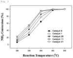
- the ammonia decomposition ability was measured under at a spatial velocity of 6,000 ml/g cat. /h at atmospheric pressure at reaction temperatures of 300°C, 350°C, 400°C, 450°C, and 500°C, and the ammonia conversion rate was calculated using Equation 1 shown below. The results are shown in Table 2 and FIG. 3 .
- Ammonia Conversion Rate % Ammonia Concentration at Reactor Inlet ⁇ Ammonia Concentration at Reactor Outlet / Ammonia Concentration at Reactor Inlet + ( Ammonia Concentration at Reactor Outlet ⁇ 100
- Table 2 shows the results of ammonia conversion rate analysis by performing ammonia dehydrogenation decomposition reactions using Catalysts 1 to 10.
- Table 2 Classificati on Catalyst type Ammonia conversion rate according to ammonia decomposition temperature 300°C 350°C 400°C 450°C 500°C ⁇ Catalyst 1> Ru/CeO 2 -cube(15) 10.2 34.0 77.9 99.8 100 ⁇ Catalyst 2> Ru/CeO 2 -cube(10) 9.2 29.6 66.4 96.4 100 ⁇ Catalyst 3> Ru/CeO 2 -cube(20) 10.2 32.4 71.8 98.7 100 ⁇ Catalyst 4> Ru/La 0.33 Ce 0.67 O 2 -cube 13.8 47.7 87.4 100 100 ⁇ Catalyst 5> Ru/CeO 2 -spindle 6.5 26.5 68.5 99.2 100 ⁇ Catalyst 6> Ru/C
- the ammonia decomposition reaction catalysts of the present invention exhibited a relatively high ammonia conversion as compared to the catalysts of the comparative examples.
- Catalysts 1 and 5 were compared with Catalyst 8, although the catalyst carriers were made of the same material, i.e., cerium (Ce), the ammonia conversion rates differed depending on the shapes of the catalyst carriers.
- the ammonia decomposition temperature was 400°C
- the ammonia conversion rates of the cerium oxide carriers were higher in this order: Ru/CeO 2 -cube > Ru/CeO 2 -spindle > Ru/CeO 2 -polycrystalline > Ru/CeO 2 -sphere > Ru/CeO 2 -rod. Therefore, it is seen that the shape of the cerium oxide carrier greatly influences the ammonia decomposition activity.
- Catalyst 11 in which the molar ratio of Cs to Ru was 1.0 exhibited a significant increase in ammonia conversion rate compared to Catalyst 20 in which the molar ratio of Cs to Ru was 0.5 over the entire temperature range.
- the most optimal performance was achieved when the molar ratio of the catalyst enhancer to Ru was 1.0.
- Table 4 shows the influence of the shape of the cerium oxide carrier in Ru catalysts containing Cs as enhancers.
- Classificati on Catalyst type Ammonia conversion rate according to ammonia decomposition temperature 300°C 350°C 400°C 450°C 500°C ⁇ Catalyst 1> Ru/CeO 2 -cube(15) 10.2 34.0 77.9 99.8 100 ⁇ Catalyst 11> Cs 1 Ru 1 /CeO 2 -Cube 22.3 54.9 95.2 100 100 ⁇ Catalyst 16> Cs 1 Ru 1 /CeO 2 -spindle 14.0 45.7 91.0 100 100 ⁇ Catalyst 17> Cs 1 Ru1/CeO 2 -polycrystalline 13.6 40.8 85.9 100 100 ⁇ Catalyst 18> Cs 1 Ru 1 /CeO 2 -sphere 11.7 40.0 84.8 100 100 ⁇ Catalyst 19> Cs 1 Ru 1 /CeO 2
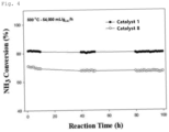
- Ammonia dehydrogenation reactions were performed for 100 hours using Catalyst 1 and Catalyst 8 to evaluate the long-term stability of the catalysts.
- the measurements were carried out at atmospheric pressure at an ammonia space velocity of 54,000 ml/g cat. /h at a reaction temperature of 500°C for 100 hours. The results are shown as ammonia conversion rates in FIG. 4 .
- Catalyst 1 exhibited a stable catalytic activity for more than 100 hours of reaction with a higher conversion rate than Catalyst 8.
- H 2 -TPR analysis was performed on Catalyst 1, Catalyst 7, Catalyst 8, Catalyst 9, Catalyst 10, Catalyst 11, Catalyst 17, and Catalyst 19.
- the H 2 -TPR analysis was performed in a manner that 0.05 g of each catalyst was heated to 110°C in an inert gas atmosphere, then the temperature of the catalyst was lowered to 35°C, and then the temperature of the catalyst was raised to 1,000°C at a rate of 10°C/min, with 10% H 2 /Ar gas being supplied.
- the results of the H 2 -TPR analysis are shown in FIGS. 5 and 6 .
- the ammonia decomposition reaction catalyst of the present invention has a good catalytic activity in ammonia decomposition reactions, thereby improving the ammonia conversion rate.
- the ammonia decomposition reaction catalyst of the present invention exhibits little deterioration in activity at elevated temperatures and for long periods of time, indicating that the catalyst has a good long-term stability.
Landscapes
- Chemical & Material Sciences (AREA)
- Organic Chemistry (AREA)
- Engineering & Computer Science (AREA)
- Chemical Kinetics & Catalysis (AREA)
- Materials Engineering (AREA)
- Inorganic Chemistry (AREA)
- General Health & Medical Sciences (AREA)
- Combustion & Propulsion (AREA)
- Health & Medical Sciences (AREA)
- Life Sciences & Earth Sciences (AREA)
- Geology (AREA)
- Analytical Chemistry (AREA)
- Physics & Mathematics (AREA)
- Thermal Sciences (AREA)
- Catalysts (AREA)
Abstract
Description
- The present application claims priority to
Korean Patent Application No. 10-2020-0116507, filed September 9, 2020 10-2021-0093386, filed July 16, 2021 - The present invention relates to a catalyst for ammonia decomposition reactions and to a hydrogen production method using the same. More particularly, the present invention relates to a catalyst for ammonia decomposition reactions, the catalyst being capable of improving an ammonia conversion rate in ammonia decomposition reactions and exhibiting long-term stability, and to a hydrogen production method using the same catalyst.
- In recent years, climate change has intensified, and hydrogen energy, which is one of the environmentally friendly fuels to replace fossil fuels, has gained attraction around the world. For the practical use of hydrogen energy, it is important to develop a technology for safely and efficiently storing and transporting hydrogen. There are several methods of storing hydrogen, but a hydrogen storage material that can reversibly store and release hydrogen is expected to be used as a hydrogen storage medium to be mounted in fuel cell vehicles.
- Hydrogen storage materials such as hydrogen storage alloys or liquid hydrogen storage members using organic compounds are disclosed. In addition, as a hydrogen production method, a method of using an ammonia decomposition reaction is disclosed.
- In connection with the method, since ammonia has an irritating odor, it is necessary to appropriately process the odor when gas exhibits an odor level that is above a predetermined threshold. Therefore, various ammonia processing methods have previously been reviewed. For example, methods of bringing ammonia into contact with oxygen so that the ammonia can be oxidized to produce water and nitrogen and methods of decomposing ammonia into nitrogen and hydrogen have been proposed.
-
Patent Document 1 discloses an ammonia processing method using a catalyst to decompose ammonia generated when disposing organic waste into nitrogen and hydrogen. The catalyst is composed of a metal oxide carrier and a catalytic material supported on the carrier. The carrier is made of alumina, silica, titania, or zirconia, and the catalytic material is nickel or a nickel oxide. In addition, at least one of an alkaline earth metal and a lanthanide element is added in the form of a metal or oxide. However, this ammonia processing method is not practical due to the low decomposition rate of ammonia. - In addition, it has recently been examined to use hydrogen recovered from an ammonia decomposition process as a hydrogen source for fuel cells, but in this case, it is required to obtain high-purity hydrogen. To obtain high-purity hydrogen using the ammonia decomposition catalysts that have been proposed so far, a high reaction temperature (for example, higher than 500°C) is required to overcome the high activation barrier (Patent Document 2) .
- To solve this problem, various catalysts using cerium oxide (CeO2) as catalyst carriers capable of decomposing ammonia at relatively low temperatures at high conversion rates have been developed. In particular, with the use of shape-controlled catalyst carriers, it is possible to control the area-to-volume ratio of the catalyst surface and the type and ratio of the crystal plane exposed, which have a significant impact on the catalytic activity of the catalyst.
- However, there are not many studies to use a cerium oxide catalyst carrier for a catalyst to be applied to an ammonia decomposition reaction, and even if there are, the study has not yet reached the commercialization stage of the cerium oxide catalyst carrier.
-
- (Patent Document 1)
Japanese Patent Application Publication No. 2004-195454 (date of publication: July 15, 2004 - Patent Document 2)
Korean Patent No. 1781412 (data of issuance: September 25, 2017 - The present invention has been made to solve the problems occurring in the related art, and objectives of the present invention are to provide an ammonia decomposition reaction catalyst capable of increasing an ammonia conversion rate in an ammonia decomposition reaction, and to provide a hydrogen production method using the same.
- In order to accomplish the above objectives, one embodiment of the present invention provides a catalyst for an ammonia decomposition reaction, the catalyst including a catalyst carrier and a catalytic activator supported on the catalyst carrier, in which the catalyst carrier is made from a cerium oxide and has at least one shape selected from the group consisting of a cube shape and spindle shape.
- In one preferred embodiment of the present invention, the catalytic activator may be one or more selected from the group consisting of ruthenium, nickel, molybdenum, iron, and cobalt.
- In one preferred embodiment of the present invention, the catalyst may include 0.1% to 50% by weight of the catalytic activator material with respect to the total weight of the catalyst.
- In one preferred embodiment of the present invention, the catalyst carrier may be a metal oxide composite in which one or more metal oxides selected from among lanthanum (La), yttrium (Y), praseodymium (Pr), neodymium (Nd), samarium (Sm), and gadolinium (Gd) are combined with a cerium oxide.
- In one preferred embodiment of the present invention, the molar ratio of cerium to metals other than cerium in the metal oxide complex may be in a range of 40:60 to 95:5.
- In one preferred embodiment of the present invention, the cube shape may have a size of 1 µm or smaller.
- In one preferred embodiment of the present invention, the catalyst may include one or more catalyst enhancers selected from the group consisting of cesium and potassium.
- In one preferred embodiment of the present invention, the catalyst may include 0.01% to 25% by weight of the catalyst enhancer with respect to the total weight of the catalyst.
- Another embodiment of the present invention provides a method of producing hydrogen from ammonia by using the ammonia decomposition reaction catalyst.
- In another preferred embodiment of the present invention, the ammonia decomposition reaction may be performed in the range of 300°C to 500°C.
- The ammonia decomposition reaction catalyst according to the present invention controls the shape of cerium oxide used as a catalyst carrier for an ammonia decomposition reaction and contains a catalyst enhancer. Thus, the ammonia decomposition reaction catalyst according to the present invention has an improved catalytic activity in an ammonia decomposition reaction, thereby improving the ammonia conversion rate. In addition, the ammonia decomposition reaction catalyst does not exhibit deterioration in catalytic activity even at elevated temperatures and during long-time reactions. That is, the ammonia decomposition reaction catalyst has good long-term stability.
-
-
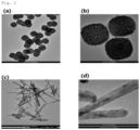
FIGS. 1A to 1D are TEM images ofCatalysts 1 to 5, in whichFIG. 1A is a TEM image of Catalyst 1,FIG. 1B is an 20X TEM image of Catalyst 1,FIG. 1C is a TEM image of Catalyst 5, andFIG. 1D is a 2X TEM image of Catalyst 5; -
FIGS. 2A to 2D are TEM images ofCatalysts 6 and 7, in whichFIG. 2A is a TEM image of Catalyst 6,FIG. 2B is a 4X TEM image of Catalyst 6,FIG. 2C is a TEM image of Catalyst 7, andFIG. 2D is a 10X TEM image of Catalyst 7; -
FIG. 3 is a graph showing measurement results of ammonia decomposition activity according to the content of catalyst enhancers in various catalysts of the present invention; -
FIG. 4 is a graph showing long-term stability measurements of Catalyst 1 andCatalyst 8 of the present invention; -
FIG. 5 is a comparative graph showing H2-TPR analysis results for some catalysts of the present invention; and -
FIG. 6 is a comparative graph showing H2-TPR analysis results of catalysts according to the content of catalyst enhancers in the catalysts of the present invention. - Unless otherwise defined, all terms including technical and scientific terms used herein have the same meaning as commonly understood by those who are ordinarily skilled in the art to which this invention belongs. In general, the nomenclature used herein is well-known and commonly used in the art.
- The terms "includes", "comprises", or "has", and the like described herein, refer to the presence of the features, figures, steps, operations, components, components, or combinations thereof described herein, and do not exclude the possibility that other features, figures, steps, operations, components, components, or combinations thereof not mentioned may be present or added.
- In one aspect, the present invention relates to a catalyst for an ammonia decomposition reaction. The catalyst includes a catalyst carrier and a catalytic activator supported on the catalyst carrier. The catalyst carrier is made from a cerium oxide and has one or more shapes selected from the group consisting of a cube shape and a spindle shape.
- At the present time, there are not many studies to apply nanoparticle catalyst carriers to ammonia decomposition reactions, and even if, the studies have not yet reached the commercialization stage. In particular, studies have never been conducted to increase the activity of ammonia dehydrogenation by varying the ratio of a specific crystal plane and a crystal surface area by controlling the shape of the catalyst carrier.
- Accordingly, the inventors of the present application have found that in the ammonia dehydrogenation reaction, there is a difference in catalytic activity depending on the shape-controlled catalyst carrier, regardless of the specific surface area of the catalyst carrier, and it is, surprisingly, possible to decompose ammonia with a higher rate than conventional arts by introducing a specific catalytic enhancer into the shape-controlled cerium oxide catalyst carrier. The inventors have made the present invention on the basis of the findings.
- In general, lattice oxygen is present in metal oxides. The lattice oxygen is highly reactive depending on their type and shape and can affect the electrical conductivity of the catalyst due to the migration of oxygen or electrons within the lattice.
- In particular, cerium is a rare earth metal that exhibits high electrical conductivity. In the case of cerium oxides controlled to have a cube shape and/or a spindle shape, such cerium oxides may limit the aggregation of catalytic activator particles due to catalytic activator-catalyst carrier interactions in high temperature ammonia dehydrogenation reactions and may provide sufficient electron density to the active catalytic material. Therefore, the cerium oxide having a particle shape that is controlled to be a cube and/or spindle shape can change the electron density of the active region of the active catalytic material, thereby improving catalyst activity and improving thermal stability and durability of the catalyst.
- To manufacture a catalyst carrier having a controlled shape, any method can be used without limitation if the method can provide a catalyst carrier having a cube shape and/or a spindle shape. Examples of the method include a hydrothermal synthesis method, a precipitation method, a polyol method, a metal ion reduction method, and an electrochemical deposition method.
- The size of the cube-shaped particles may be in a range of 1 um or less, preferably in a range of 5 nm to 100 nm, more preferably in a range of 10 nm to 30 nm, and most preferably in a range of 12 nm to 18 nm. When the size of the cube-shaped particles is larger than 1 um, the effect of enhancing the catalytic activity is not significant.
- The catalyst carrier according to the present invention may be made from a metal oxide composite that is a composite of cerium oxide and one or more metal oxides of one or more metals selected from among lanthanum (La), yttrium (Y), praseodymium (Pr), neodymium (Nd), samarium (Sm), and gadolinium (Gd). The metal oxide composite may have a cube shape and/or a spindle shape.
- The metal oxide composite may contain 40% to 95% by mole of cerium, and preferably 50% to 90% by mole of cerium.
- To manufacture a catalyst carrier having a controlled shape, any method can be used without limitation if the method can provide a catalyst carrier having a cube shape and/or a spindle shape. Examples of the method include a hydrothermal synthesis method, a precipitation method, a polyol method, a metal ion reduction method, and an electrochemical deposition method.
- The active catalytic material supported on the catalyst carrier may be one or more metals selected from the group consisting of ruthenium, nickel, molybdenum, iron, and cobalt. Preferably, the active catalytic material may be ruthenium.
- The degrees that D-bands of metals commonly used as active catalytic materials are filled with electrons have relations with the adsorption energy levels of nitrogen and metals, and also have relations with the efficiency of ammonia dehydrogenation. Specifically, the more the D-band is filled with electrons, the lower the adsorption energy level of the active catalytic material and nitrogen. On the contrary, the less the D-band is filled with electrons, the lower the adsorption energy level of the active catalytic material and nitrogen. When ruthenium is used as an active catalytic material, the nitrogen adsorption energy is low but is not optimal. Accordingly, according to the present invention, it is possible to change the electron density in the D-band of ruthenium and the optimal nitrogen binding energy level by using a predetermined metal oxide and cerium oxide having a controlled shape as a catalyst carrier, thereby increasing the ammonia dehydrogenation activity.
- The active catalytic material may be contained in an amount of 0.1% to 50% by weight with respect to the total weight of the catalyst. When the active catalytic material is contained in an amount of less than 0.1% by weight, it is difficult to expect performance improvement. When the active catalytic material is contained in an amount of more than 50% by weight, agglomeration occurs between the active catalytic material particles, resulting in deterioration in the catalyst performance.
- In addition, the ammonia decomposition reaction catalyst according to the present invention may include one or more catalyst enhancers selected from the group consisting of cesium and potassium. The catalyst enhancer is expected to provide electrons to the active catalytic material such as ruthenium (Ru) in an ammonia decomposition reaction, thereby increasing the electron density. Therefore, in the dissociation and adsorption of nitrogen, which is a crucial step in the ammonia decomposition reaction, nitrogen molecules can easily separate, resulting in improvement in the efficiency of the ammonia decomposition reaction.
- The content of the catalyst enhancer may be determined depending on the content of the active catalytic material. Preferably, the catalyst enhancer may be contained in an amount in a range of 0.01% to 25% by weight, relative to the total weight of the catalyst, and more preferably in a range of 0.5% to 10% by weight. When the content of the catalyst enhancer is less than 0.01% by weight, it may be difficult to expect an effect of enhancing the catalytic activity. When the content is greater than 25% by weight, the increase in catalytic activity is not significant in view of the increase in the content of the catalyst enhancer.
- Any catalyst preparation method can be used without limitation if the method can support an active catalytic material on a catalyst carrier, or an active catalytic material and a catalyst enhancer on a catalyst carrier by reacting and heat-treating the catalyst carrier and an active catalytic material precursor, or the catalyst carrier, the active catalytic material precursor, and a catalyst enhancer. Examples of the method include a deposition-precipitation (DP) method, a dry impregnation method, a wet impregnation method, a sol-gel method, a hydrothermal synthesis method, and a polyol method.
- The active catalytic material precursor may be one or more compounds selected from the group consisting of inorganic compounds and organic compounds including active catalytic material ions. Specifically, the active catalytic material precursor may be chloride, hydrate, nitride, acetylacetonate, iodide, or the like.
- In addition, the precursor of the catalyst enhancer may be one or more compounds selected from the group comprising inorganic compounds and organic compounds including catalyst enhancer ions. Specifically, the catalyst enhancer precursor may be a hydroxide, chloride, nitride, carbonate, fluoride, acetate, or the like of cesium or potassium.
- The catalyst for ammonia decomposition reactions described above is improved in catalytic activity, thermal stability, and durability, thereby improving the ammonia conversion rate in ammonia decomposition reactions and exhibiting long-term stability even at high temperatures and for long periods of time.
- In another aspect, the present invention relates to a hydrogen production method using the ammonia decomposition catalyst. The method produces hydrogen from ammonia.
- The hydrogen production method according to the present invention can process gas containing ammonia with the use of the ammonia decomposition catalyst which uses a cube-shaped and/or spindle-shaped cerium oxide as a catalyst carrier, and dehydrogenate the ammonia into nitrogen and hydrogen, thereby producing hydrogen.
- The ammonia decomposition catalyst exhibits an ammonia conversion rate of 80% or more at a temperature in the range of 400°C to 500°C, and more particularly exhibits an ammonia conversion rate of 96% or more at a temperature in the range of 450°C to 500°C.
- The present invention will be described in more detail with reference to examples described below. The examples described below are presented only to help understanding of the present invention, and the scope of the present invention is not limited thereto.
- A solution prepared from 12.0 g of NaOH (97%, Daejung) and 40 ml of deionized water was added dropwise to a solution obtained by dissolving 1.3 g of Ce(NO3)3 ·6H2O (Sigma, 99%) in 30 ml of distilled water. The solution was then mixed in a 100 ml Teflon bottle and stirred continuously for 30 minutes. Finally, the Teflon bottle was put into a stainless steel container autoclave, sealed, and heated at 160°C for 24 hours. The resulting precipitate was then collected, washed several times with deionized water and ethanol, dried in an oven at 80°C for 24 hours, and then fired at 500°C for 4 hours to obtain a cube-shaped CeO2 catalyst carrier having a particle size of 15 nm.
- A solution prepared from 12 g of NaOH (97%, Daejung) and 40 ml of deionized water was added dropwise to a solution obtained by dissolving 0.65 g of Ce(NO3)3·6H2O (Sigma, 99%) in 30 ml of distilled water. The solution was then mixed in a 100 ml Teflon bottle and stirred continuously for 30 minutes. Finally, the Teflon bottle was put into and in a stainless steel container autoclave, sealed, and heated at 160°C for 24 hours. The resulting precipitate was then collected, washed several times with deionized water and ethanol, dried in an oven at 80°C for 24 hours, and then fired at 500°C for 4 hours to obtain a cube-shaped CeO2 catalyst carrier having a particle size of 10 nm.
- A solution prepared from 12 g of NaOH (97%, Daejung) and 40 ml of deionized water was added dropwise to a solution obtained by dissolving 2.6 g of Ce(NO3)3·6H2O (99%, Sigma) in 30 ml of distilled water. The solution was then mixed in a 100 ml Teflon bottle and stirred continuously for 30 minutes. Finally, the Teflon bottle was put into a stainless steel container autoclave, sealed, and heated at 160°C for 24 hours. The resulting precipitate was then collected, washed several times with deionized water and ethanol, dried in an oven at 80°C for 24 hours, and then fired at 500°C for 4 hours to obtain a cube-shaped CeO2 catalyst carrier having a particle size of 20 nm.
- To 70 ml of deionized water was dissolved 2.6 g of Ce(NO3)3·6H2O (99%, Sigma) and 1 g of urea (99%, Samchun) . The mixture was transferred to a 100 ml Teflon-lined autoclave, then heated to 120°C, and maintained at this temperature for 8 hours. The resulting precipitate was then collected, washed several times with deionized water and ethanol, and then dried in a vacuum oven at 80 °C for 12 hours. The dried matter was then calcined in air at 400°C for 3 hours to obtain a spindle-shaped CeO2 catalyst carrier.
- A solution obtained by adding 19.2 g of NaOH (97%, Daejung) to 50 ml of deionized water was added dropwise to a solution obtained by dissolving 1.73 g of Ce(NO3)3·6H2O (99%, Sigma) and 0.87 g of La(NO3)3·6H2O (99%, Sigma) in 30 ml of distilled water. The solutions were then mixed in a 100 ml Teflon bottle and stirred continuously for 30 minutes. Finally, the Teflon bottle was put into in a stainless steel container autoclave, sealed, and heated at 180°C for 12 hours. The resulting precipitate was then collected, washed several times with deionized water and ethanol, and dried in an oven at 80°C for 24 hours to produce La0.33 Ce0.67O2-cube, which is a composite oxide having a cube shape and a La-to-Ce molar ratio of 0.33:0.67.
- To 3 ml of deionized water, 2.6 g of Ce(NO3)3·6H2O (99.8%, Sigma) was added dropwise 3 ml of acetic acid (99.7%, Junsei) and ethylene glycol (99.8%, Sigma). The solution was then mixed in a 100 ml Teflon bottle and stirred continuously for 30 minutes. Finally, the Teflon bottle was put into a stainless steel container autoclave, sealed, and heated at 180°C for 3.5 hours. The resulting precipitate was then collected, washed several times with deionized water and ethanol, dried in an oven at 80°C for 12 hours, and then fired at 500°C for 4 hours to obtain a sphere-shaped CeO2 catalyst carrier.
- 28.7 g of NaOH (97%, Daejung) and 2.6 g of Ce(NO3)3·6H2O (99%, Sigma) (OH-/Ce3+ = 120 in molar ratio) were dissolved in 50 ml and 30 ml of deionized water, respectively. The two solutions were then mixed in a 100 ml Teflon bottle and continuously stirred for 30 minutes. Finally, the Teflon bottle was put into a stainless steel container autoclave, sealed, and heated at 100°C for 24 hours. The resulting precipitate was then collected, washed several times with deionized water and ethanol, dried in an oven at 60°C for 24 hours, and then fired at 500°C for 4 hours to obtain a rod-shaped CeO2 catalyst carrier.
- To a solution obtained by dissolving 7.57 g Ce(NO3)3·6H2O (99%, Sigma) in 100 ml of deionized water was added dropwise to 1.0 M NH4 OH at a rate of 60 ml/h until the pH of the solution reached about 9. The solution was then stirred for 24 hours. The resulting precipitate was then collected, washed several times with deionized water and ethanol, dried in a vacuum oven at 110°C for 12 hours, and then fired at 500°C for 4 hours to obtain a polycrystalline CeO2 catalyst carrier.
- A ruthenium-based catalyst was prepared by using the catalyst carrier of
Carrier 1. First, 1.0 g of the catalyst carrier ofCarrier 1 was suspended in 50 ml of deionized water, and then 0.04 g of RuCl3·xH2O (99.98%, Sigma) was added to the suspension. The suspension was adjusted with a solution of NH4OH 0.5 M until the pH of the suspension became 9.0. The NH4OH 0.5 M solution was prepared by diluting 16.3 ml of NH4OH (28% to 30%, Samchun) with deionized water to make 0.5 L of final solution. The adjusted suspension was aged under stirring at 400 rpm at room temperature for 12 hours. The resulting precipitate was then filtered off, washed several times with deionized water and ethanol, and then dried at 110°C for 12 hours to prepare an ammonia decomposition reaction catalyst in which 2% by weight of ruthenium was supported. The catalyst prepared was designated Ru/CeO2-cube(15). - An ammonia decomposition reaction catalyst was prepared in the same manner as
catalyst 1 except that the catalyst carrier forCatalyst 1 was replaced with Carrier 2. In the example, 2% by weight of ruthenium was contained. The catalyst prepared was designated Ru/CeO2-cube(10). - An ammonia decomposition reaction catalyst was prepared in the same manner as
catalyst 1 except that the catalyst carrier forCatalyst 1 was replaced with Carrier 3. In the example, 2% by weight of ruthenium was contained. The catalyst prepared was designated Ru/CeO2-cube(20). - An ammonia decomposition reaction catalyst was prepared in the same manner as
catalyst 1 except that the catalyst carrier forCatalyst 1 was replaced with Carrier 5. In the example, 2% by weight of ruthenium was contained. The catalyst prepared was designated Ru/La0.33Ce0.67O2-cube. - An ammonia decomposition reaction catalyst was prepared in the same manner as
catalyst 1 except that the catalyst carrier forCatalyst 1 was replaced with Carrier 4. In the example, 2% by weight of ruthenium was contained. The catalyst prepared was designated Ru/CeO2-spindle. - An ammonia decomposition reaction catalyst was prepared in the same manner as
catalyst 1 except that the catalyst carrier forCatalyst 1 was replaced with Carrier 6. In the example, 2% by weight of ruthenium was contained. The catalyst prepared was designated Ru/CeO2-sphere. - An ammonia decomposition reaction catalyst was prepared in the same manner as
catalyst 1 except that the catalyst carrier forCatalyst 1 was replaced withCarrier 7. In the catalyst of this example, 2% by weight of ruthenium was contained. The catalyst prepared was designated Ru/CeO2-rod. - An ammonia decomposition reaction catalyst was prepared in the same manner as
catalyst 1 except that the catalyst carrier forCatalyst 1 was replaced withCarrier 8. In the example, 2% by weight of ruthenium was contained. The catalyst prepared was designated Ru/CeO2-polycrystalline. - An ammonia decomposition reaction catalyst was prepared in the same manner as
Catalyst 1 except that the catalyst carrier forCatalyst 1 was replaced with Al2O3 (gamma phase, Sigma). In this catalyst, 2% by weight of ruthenium was contained. The catalyst prepared was designated Ru/Al2O3. - An ammonia decomposition reaction catalyst was prepared in the same manner as
Catalyst 1 except that the catalyst carrier forCatalyst 1 was replaced with MgO (Sigma). In the catalyst of this example, 2% by weight of ruthenium was contained. The catalyst prepared was designated Ru/MgO. - A ruthenium-based catalyst was prepared through a wet-impregnation (WI)
method using Carrier 1. First, 1.0 g of the catalyst carrier ofCarrier 1 was suspended in 30 ml of deionized water and stirred for 30 minutes. Next, 1.25 ml of Ru(NO) (NO3)x(OH)y (x + y = 3, Ru 1.5%, Sigma) and 4.95 ml of 0.04 M CsNOs were added to the suspension at the same time, and the solution was stirred for another 30 minutes. The stirred solution was aged with a rotary evaporator at a temperature of 60°C, a pressure of 72 mbar, and a rotation speed of 150 rpm for 4 hours. The resulting precipitate was then dried at 110°C for 12 hours to prepare an ammonia decomposition reaction catalyst in which ruthenium was supported in an amount of 2% by weight and cesium was supported in an amount of 2.6% by weight. The catalyst prepared was designated Cs1Ru1/CeO2-Cube. - A catalyst was prepared in the same manner as
Catalyst 11 except that 4.95 ml of KnO3 was used instead of 4.95 ml of 0.04 M CsNO3 as a catalyst enhancer precursor. In this ammonia decomposition reaction catalyst (K:Ru molar ratio = 1.0), 2% by weight of ruthenium and 0.8% by weight of potassium were supported. The catalyst prepared was designated K1Ru1/CeO2-Cube. - A catalyst was prepared in the same manner as
Catalyst 11 except that 4.95 ml of Ba(NO3)2 was used instead of 4.95 ml of 0.04 M CsNOs as a catalyst enhancer precursor. In this ammonia decomposition reaction catalyst (Ba:Ru molar ratio = 1.0), 2% by weight of ruthenium and 2.6% by weight of barium were supported. The catalyst prepared was designated Ba1Ru1/CeO2-Cube. - A catalyst was prepared in the same manner as
Catalyst 11 except that 4.95 ml of NaNOs was used instead of 4.95 ml of 0.04 M CsNOs as a catalyst enhancer precursor. In this ammonia decomposition reaction catalyst (Na:Ru molar ratio = 1.0), 2% by weight of ruthenium and 0.4% by weight of sodium were supported. The catalyst prepared was designated Na1Ru1/CeO2-Cube. - A catalyst was prepared in the same manner as
Catalyst 11 except that 4.95 ml of Ca(NO3)2 was used instead of 4.95 ml of 0.04 M CsNO3 as a catalyst enhancer precursor. In this ammonia decomposition reaction catalyst (Ca:Ru molar ratio = 1.0), 2% by weight of ruthenium and 0.8% by weight of calcium were supported. The catalyst prepared was designated Ca1Ru1/CeO2-Cube. - A catalyst was prepared in the same manner as
Catalyst 11 except that Carrier 4 was used instead ofCarrier 1. In this ammonia decomposition reaction catalyst, 2% by weight of ruthenium and 2.6% by weight of cesium were supported. The catalyst prepared was designated Cs1Ru1/CeO2-spindle. - A catalyst was prepared in the same manner as
Catalyst 11 except forCarrier 8 being used. In the ammonia decomposition reaction catalyst, 2% by weight of ruthenium and 0.8% by weight of calcium were supported. The catalyst prepared was designated Ca1Ru1/CeO2-polycrystalline. - A catalyst was prepared in the same manner as
Catalyst 11 except for Carrier 6 being used. In the ammonia decomposition reaction catalyst, 2% by weight of ruthenium and 0.8% by weight of calcium were supported. The catalyst prepared was designated Ca1Ru1/CeO2-sphere. - A catalyst was prepared in the same manner as
Catalyst 11 except forCarrier 7 being used. In the ammonia decomposition reaction catalyst, 2% by weight of ruthenium and 0.8% by weight of calcium were supported. The catalyst prepared was designated Ca1Ru1/CeO2-rod. - A catalyst was prepared in the same manner as
Catalyst 11 except that 0.47 ml of 0.04 M CsNOs was used instead of 4.95 ml of 0.04 M CsNOs. In the ammonia decomposition reaction catalyst, 2% by weight of ruthenium and 1.3% by weight of cesium were supported. The catalyst prepared was designated Cs0.5Ru1/CeO2-cube. - A catalyst was prepared in the same manner as
Catalyst 11 except that 9.9 ml of 0.04 M CsNOs was used instead of 4.95 ml of 0.04 M CsNO3. In the ammonia decomposition reaction catalyst, 2% by weight of ruthenium and 5.2% by weight of cesium were supported. The catalyst prepared was designated Cs2Ru1/CeO2-cube. - The shape and physical properties of
Catalysts 1, 4, and 5 andCatalysts FIGS. 1A to 1D ,FIGS. 2A to 2D , and Table 1. - In the BET specific surface area analysis of catalyst carriers, degassing was performed at 300°C for 5 hours, nitrogen physical adsorption was performed at -196°C, and the specific surface area was obtained using the BET model.
- The dispersibility of Ru, which is an active material, was used with the CO pulse chemisorption technique. First, heat treatment was performed at 100°C in a pure oxygen atmosphere for 30 minutes, and then purging was performed. Next, a reduction reaction was performed at 500°C in a hydrogen atmosphere for 2 hours, and gas adsorption was performed at 35°C in order of helium (30 minutes) - oxygen (30 minutes) - helium (30 minutes) - carbon dioxide (30 minutes) - helium (30 minutes) - hydrogen (30 minutes) - helium (30 minutes). Finally, the amount of CO adsorption was obtained by injecting CO so that CO/Ru = 1.
[Table 1] Classificati on Catalyst type Specific surface area of catalyst carrier: Sbet(m2/g) Ru Dispersion (%) < Catalyst 1>Ru/CeO2-cube(15) 23 25.6 <Catalyst 4> Ru/La0.33Ce0.67O2- cube 19 16.3 <Catalyst 5> Ru/CeO2-spindle 104 9.8 <Catalyst 6> Ru/CeO2-sphere 162 85.5 < Catalyst 7>Ru/CeO2-rod 65 16.9 < Catalyst 8>Ru/CeO2-polycrystalline 65 38.4 - As illustrated in
FIGS. 1A to 1D andFIGS. 2A to 2D , the catalyst carriers of the present invention were prepared to have specific shapes by controlling the shape of the particles according to the method of the present invention. - In addition, as shown in Table 1, the catalyst carriers differ in specific surface area and dispersibility of ruthenium according to the shapes of the catalyst carriers.
- Ammonia dehydrogenation decomposition reactions were performed using the catalysts prepared as described above to determine ammonia conversion rates. The ammonia decomposition ability was measured under at a spatial velocity of 6,000 ml/gcat./h at atmospheric pressure at reaction temperatures of 300°C, 350°C, 400°C, 450°C, and 500°C, and the ammonia conversion rate was calculated using
Equation 1 shown below. The results are shown in Table 2 andFIG. 3 .
- Table 2 below shows the results of ammonia conversion rate analysis by performing ammonia dehydrogenation decomposition
reactions using Catalysts 1 to 10.[Table 2] Classificati on Catalyst type Ammonia conversion rate according to ammonia decomposition temperature 300°C 350°C 400°C 450°C 500°C < Catalyst 1>Ru/CeO2-cube(15) 10.2 34.0 77.9 99.8 100 <Catalyst 2> Ru/CeO2-cube(10) 9.2 29.6 66.4 96.4 100 <Catalyst 3> Ru/CeO2-cube(20) 10.2 32.4 71.8 98.7 100 <Catalyst 4> Ru/La0.33Ce0.67O2-cube 13.8 47.7 87.4 100 100 <Catalyst 5> Ru/CeO2-spindle 6.5 26.5 68.5 99.2 100 <Catalyst 6> Ru/CeO2-sphere 5.1 23.6 60.8 97.0 100 < Catalyst 7>Ru/CeO2-rod 3.5 17.2 52.5 96.5 100 < Catalyst 8>Ru/CeO2-polycrystalline 5.5 24.2 61.8 96.3 100 < Catalyst 9>Ru/Al2O3 7.0 23.1 53.6 84.6 99.4 < Catalyst 10>Ru/MgO 7.6 23.6 54.1 88.1 99.8 - As shown in Table 2, the ammonia decomposition reaction catalysts of the present invention exhibited a relatively high ammonia conversion as compared to the catalysts of the comparative examples.
- When
Catalyst 1 is compared withCatalysts - When
Catalysts 1 and 5 were compared withCatalyst 8, although the catalyst carriers were made of the same material, i.e., cerium (Ce), the ammonia conversion rates differed depending on the shapes of the catalyst carriers. When the ammonia decomposition temperature was 400°C, the ammonia conversion rates of the cerium oxide carriers were higher in this order: Ru/CeO2-cube > Ru/CeO2 -spindle > Ru/CeO2-polycrystalline > Ru/CeO2-sphere > Ru/CeO2-rod. Therefore, it is seen that the shape of the cerium oxide carrier greatly influences the ammonia decomposition activity. - On the other hand, when
Catalyst 1 was compared with Catalyst 3, the ammonia decomposition activity changed depending on the particle size of the cerium oxide. When the cerium oxide had a cube shape, the catalytic activity was highest at a particle size of about 15 nm, was second highest at a particle size of 20 nm and was next highest at a particle size of 10 nm. - Table 3 below shows the results of catalytic activity analysis in which different catalyst enhancers were used in ammonia decomposition reactions.
[Table 3] Classificati on Catalyst type Ammonia conversion rate according to ammonia decomposition temperature 300°C 350°C 400°C 450°C 500°C < Catalyst 1>Ru/CeO2-cube(15) 10.2 34.0 77.9 99.8 100 < Catalyst 11>Cs1Ru1/CeO2-cube 22.3 54.9 95.2 100 100 <Catalyst 12> K1Ru1/CeO2-cube 12.7 40.9 84.5 100 100 <Catalyst 13> Ba1Ru1/CeO2-cube 6.4 25.2 64.6 97.7 100 <Catalyst 14> Na1Ru1/CeO2-cube 5.2 23.4 62.5 98.3 100 <Catalyst 15> Ca1Ru1/CeO2-cube 4.4 20.8 57.1 95.3 100 - When Ru, Ba, Na, or Ca was introduced into a Ru-based ammonia decomposition catalyst, the catalytic activity decreased. However, when Cs or K was introduced, the catalytic activity for ammonia decomposition increased compared to the case where Ru was used alone. When Cs was introduced, the activity dramatically increased. That is, Cs and the like can be used as catalyst enhancers to significantly enhance the activity of ammonia decomposition catalysts. In addition, the activity increase effect according to the content of the catalyst enhancer is shown in
FIG. 3 . The ammonia conversion rate varied with the change in content of the catalyst enhancer (Catalysts Catalyst 11 in which the molar ratio of Cs to Ru was 1.0 exhibited a significant increase in ammonia conversion rate compared toCatalyst 20 in which the molar ratio of Cs to Ru was 0.5 over the entire temperature range.Catalyst 21 in which the molar ratio of Cs to Ru was 2.0, which was higher than that ofCatalyst 20, exhibited a decrease in ammonia conversion rate. On the basis of the experiment results, it was confirmed that the most optimal performance was achieved when the molar ratio of the catalyst enhancer to Ru was 1.0. - Table 4 below shows the influence of the shape of the cerium oxide carrier in Ru catalysts containing Cs as enhancers.
[Table 4] Classificati on Catalyst type Ammonia conversion rate according to ammonia decomposition temperature 300°C 350°C 400°C 450°C 500°C < Catalyst 1>Ru/CeO2-cube(15) 10.2 34.0 77.9 99.8 100 < Catalyst 11>Cs1Ru1/CeO2-Cube 22.3 54.9 95.2 100 100 <Catalyst 16> Cs1Ru1/CeO2-spindle 14.0 45.7 91.0 100 100 < Catalyst 17>Cs1Ru1/CeO2-polycrystalline 13.6 40.8 85.9 100 100 <Catalyst 18> Cs1Ru1/CeO2-sphere 11.7 40.0 84.8 100 100 < Catalyst 19>Cs1Ru1/CeO2-rod 9.8 37.2 80.1 99.5 100 - In Table 4, there is a difference in the activity of the ammonia decomposition catalyst according to the shape of the carrier in the Ru catalyst in which Cs is included as an enhancer. When the reaction temperature is 400°C, the activity is in this order: Ru/CeO2-cube > Ru/CeO2-spindle > Ru/CeO2-polycrystalline > Ru/CeO2-sphere > Ru/CeO2-rod. That is, the order of the activity levels of the catalysts is the same as in Table 2 showing the activity levels for the case where the enhancers are not used. Therefore, it is assumed that the effect of the enhancers is not influenced by the shape of the catalyst carrier.
- Ammonia dehydrogenation reactions were performed for 100
hours using Catalyst 1 andCatalyst 8 to evaluate the long-term stability of the catalysts. The measurements were carried out at atmospheric pressure at an ammonia space velocity of 54,000 ml/gcat./h at a reaction temperature of 500°C for 100 hours. The results are shown as ammonia conversion rates inFIG. 4 . - As shown in
FIG. 4 , it was confirmed thatCatalyst 1 exhibited a stable catalytic activity for more than 100 hours of reaction with a higher conversion rate thanCatalyst 8. - H2-TPR analysis was performed on
Catalyst 1,Catalyst 7,Catalyst 8,Catalyst 9,Catalyst 10,Catalyst 11,Catalyst 17, andCatalyst 19. The H2-TPR analysis was performed in a manner that 0.05 g of each catalyst was heated to 110°C in an inert gas atmosphere, then the temperature of the catalyst was lowered to 35°C, and then the temperature of the catalyst was raised to 1,000°C at a rate of 10°C/min, with 10% H2/Ar gas being supplied. The results of the H2 -TPR analysis are shown inFIGS. 5 and6 . - As illustrated in
FIG. 5 , when Cs was added as an enhancer, the Ru reduction peak moved toward an increased temperature, and the area of the Ru reduction peak increased. From this result, it is seen that the addition of Cs enhances the interaction between Ru and the carrier (CeO2) and increases the relative content of the Ru active species. - In addition, as illustrated in
FIG. 6 , when the molar ratio of Cs to Ru is 1.0, the temperature at which the reducing peak of Ru occurs is shifted to the highest temperature as compared to the case where the molar ratio of Cs to Ru is 0.5 or 2.0. From this result, it is seen that enhanced interaction between Ru and the carrier and a relatively high content of Ru active species are key factors to increase the ammonia conversion rate. - Therefore, the ammonia decomposition reaction catalyst of the present invention has a good catalytic activity in ammonia decomposition reactions, thereby improving the ammonia conversion rate. In addition, the ammonia decomposition reaction catalyst of the present invention exhibits little deterioration in activity at elevated temperatures and for long periods of time, indicating that the catalyst has a good long-term stability.
- Although the present invention has been described with reference to the embodiments, other embodiments may be configured within the spirit and scope of the present invention. Accordingly, the scope of the present invention is defined only by the appended claims and their equivalents and is not limited by the specific embodiments described herein.
Claims (10)
- A catalyst for an ammonia decomposition reaction, the catalyst comprising a catalyst carrier and an active catalytic material supported on the catalyst carrier, wherein
the catalyst carrier is made of a cerium oxide having one or more shapes selected from the group consisting of a cube shape and a spindle shape. - The catalyst of claim 1, wherein the active catalytic material is one or more metals selected from the group consisting of ruthenium, nickel, molybdenum, iron, and cobalt.
- The catalyst of claim 1, wherein the active catalytic material is contained in an amount of 0.1% by weight to 50% by weight relative to the total weight of the catalyst.
- The catalyst of claim 1, wherein the catalyst carrier is a metal oxide composite of cerium oxide and one or more metal oxides of one or more metals selected from lanthanum o(La), yttrium (Y), praseodymium (Pr), neodymium (Nd), samarium (Sm), and gadolinium (Gd).
- The catalyst of claim 4, wherein the molar ratio of cerium to the other metal in the metal oxide composite is in a range of 40:60 to 95:5.
- The catalyst of claim 1, wherein the cube-shaped catalyst carrier has a size of 1 µm or smaller.
- The catalyst of claim 1, further comprising one or more catalyst enhancers selected from the group consisting of cesium and potassium.
- The catalyst of claim 7, wherein the one or more catalyst enhancers are contained in an amount of 0.01% by weight to 25% by weight relative to the total weight of the catalyst.
- A method of producing hydrogen from ammonia by using the catalyst of any one of claims 1 to 8.
- The method of claim 9, wherein an ammonia decomposition reaction is carried out in a range of 300°C to 500°C.
Applications Claiming Priority (3)
| Application Number | Priority Date | Filing Date | Title |
|---|---|---|---|
| KR20200116507 | 2020-09-11 | ||
| KR1020210093386A KR102606592B1 (en) | 2020-09-11 | 2021-07-16 | Catalyst for Decomposing Ammonia and Method for Generating Hydrogen Using the Same |
| PCT/KR2021/012140 WO2022055225A1 (en) | 2020-09-11 | 2021-09-07 | Ammonia decomposition catalyst and hydrogen production method using same |
Publications (2)
| Publication Number | Publication Date |
|---|---|
| EP4212243A1 true EP4212243A1 (en) | 2023-07-19 |
| EP4212243A4 EP4212243A4 (en) | 2024-11-13 |
Family
ID=80631966
Family Applications (1)
| Application Number | Title | Priority Date | Filing Date |
|---|---|---|---|
| EP21867091.7A Pending EP4212243A4 (en) | 2020-09-11 | 2021-09-07 | AMMONIA DECOMPOSITION CATALYST AND HYDROGEN PRODUCTION PROCESS THEREOF |
Country Status (5)
| Country | Link |
|---|---|
| US (1) | US20240367154A1 (en) |
| EP (1) | EP4212243A4 (en) |
| JP (1) | JP7525731B2 (en) |
| CN (1) | CN116056789B (en) |
| WO (1) | WO2022055225A1 (en) |
Families Citing this family (15)
| Publication number | Priority date | Publication date | Assignee | Title |
|---|---|---|---|---|
| KR102544718B1 (en) * | 2021-03-15 | 2023-06-20 | 한국화학연구원 | Catalyst for Decomposing Ammonia, Method of Preparing the Same and Method for Generating Hydrogen Using the Same |
| US11724245B2 (en) | 2021-08-13 | 2023-08-15 | Amogy Inc. | Integrated heat exchanger reactors for renewable fuel delivery systems |
| US12000333B2 (en) | 2021-05-14 | 2024-06-04 | AMOGY, Inc. | Systems and methods for processing ammonia |
| EP4352008A4 (en) | 2021-06-11 | 2025-07-02 | Amogy Inc | SYSTEMS AND METHODS FOR PROCESSING AMMONIA |
| US11539063B1 (en) | 2021-08-17 | 2022-12-27 | Amogy Inc. | Systems and methods for processing hydrogen |
| CN115318317B (en) * | 2022-08-26 | 2024-05-14 | 常州大学 | A method for preparing an ammonia decomposition catalyst and its product |
| US11834334B1 (en) | 2022-10-06 | 2023-12-05 | Amogy Inc. | Systems and methods of processing ammonia |
| US11866328B1 (en) | 2022-10-21 | 2024-01-09 | Amogy Inc. | Systems and methods for processing ammonia |
| US11795055B1 (en) | 2022-10-21 | 2023-10-24 | Amogy Inc. | Systems and methods for processing ammonia |
| CN115888740B (en) * | 2022-11-10 | 2024-08-20 | 西安交通大学 | A spherical iron-based metal catalyst for catalyzing hydrogen production from ammonia and a preparation method thereof |
| CN115684423A (en) * | 2022-11-10 | 2023-02-03 | 西安交通大学 | An experimental platform for hydrogen production from ammonia with plasma co-catalysts |
| KR20250089313A (en) | 2023-12-11 | 2025-06-18 | 포스코홀딩스 주식회사 | Catalyst for ammonia decomposition and method for manufacturing the same |
| KR20250091976A (en) | 2023-12-14 | 2025-06-23 | 포스코홀딩스 주식회사 | Support, method for manufacturing support, and catalyst for ammonia decomposition containing support |
| KR20250093750A (en) | 2023-12-15 | 2025-06-25 | 포스코홀딩스 주식회사 | Ammonia decomposition system |
| KR20250096209A (en) * | 2023-12-20 | 2025-06-27 | 에스케이이노베이션 주식회사 | Catalyst for ammonia decomposition and method of preparing catalyst for ammonia decomposition |
Family Cites Families (23)
| Publication number | Priority date | Publication date | Assignee | Title |
|---|---|---|---|---|
| JP4705752B2 (en) | 2002-12-04 | 2011-06-22 | メタウォーター株式会社 | Energy recovery from ammonia from waste treatment |
| US7824656B2 (en) * | 2005-03-24 | 2010-11-02 | University Of Regina | Catalysts for hydrogen production |
| JP2010214225A (en) * | 2009-03-13 | 2010-09-30 | Nippon Shokubai Co Ltd | Ammonia decomposition catalyst, and method of decomposing ammonia using the same |
| JP5763890B2 (en) | 2009-03-17 | 2015-08-12 | 株式会社日本触媒 | Hydrogen production catalyst and hydrogen production method using the same |
| JP5483705B2 (en) * | 2009-03-17 | 2014-05-07 | 株式会社日本触媒 | Hydrogen production catalyst and hydrogen production method using the same |
| JP5430224B2 (en) * | 2009-05-21 | 2014-02-26 | 日立造船株式会社 | Hydrogen production system |
| JP2011056488A (en) | 2009-09-09 | 2011-03-24 | Yusaku Takita | Ammonia reforming catalyst and method of manufacturing hydrogen using the same |
| KR101167098B1 (en) * | 2010-11-29 | 2012-07-20 | 연세대학교 산학협력단 | Catalyst for preferential oxidation and Method for manufacturing the same |
| JP6027467B2 (en) | 2013-03-14 | 2016-11-16 | 田中貴金属工業株式会社 | Ammonia reforming catalyst and method for producing the same |
| EP3227020A1 (en) * | 2014-12-01 | 2017-10-11 | SABIC Global Technologies B.V. | Synthesis of trimetallic nanoparticles by homogeneous deposition precipitation, and application of the supported catalyst for carbon dioxide reforming of methane |
| KR101781412B1 (en) | 2015-06-02 | 2017-09-25 | 한국과학기술연구원 | Catalysts for ammonia dehydrogenation, methods of producing the same, and methods of producing hydrogen gas from ammonia using the same |
| JP6751606B2 (en) | 2016-07-01 | 2020-09-09 | 株式会社日本触媒 | Ammonia decomposition catalyst and method for producing hydrogen-containing gas using this catalyst |
| KR101985174B1 (en) * | 2017-07-10 | 2019-06-04 | 한국과학기술연구원 | Catalyst for hydrodeoxygenation and methods for preparing the same |
| EP3689823A4 (en) * | 2017-09-25 | 2021-06-30 | Japan Science and Technology Agency | COMPOSITE OXIDE, METAL SUPPORT MATERIAL AND AMMONIA SYNTHESIS CATALYST |
| CN109954493A (en) * | 2017-12-14 | 2019-07-02 | 中国科学院大连化学物理研究所 | Rare earth metal oxide supported ruthenium catalyst for hydrogen production by ammonia decomposition and its preparation and application |
| JP7264154B2 (en) * | 2018-03-26 | 2023-04-25 | 株式会社レゾナック | Ammonia decomposition catalyst, method for producing the same, and method for producing hydrogen gas |
| US11891301B2 (en) * | 2018-08-21 | 2024-02-06 | University Of South Carolina | Ammonia decomposition catalyst systems |
| CN111215086A (en) * | 2018-11-25 | 2020-06-02 | 中国科学院大连化学物理研究所 | Application of rare earth oxide loaded transition metal catalyst in ammonia decomposition reaction |
| KR102241516B1 (en) * | 2018-12-19 | 2021-04-19 | 한국과학기술연구원 | Ruthenium based zeolite based catalysts for ammonia dehydrogenation, method of forming the same and method of producing hydrogen gas from ammonia using the same |
| CN109675556A (en) * | 2019-01-04 | 2019-04-26 | 华东理工大学 | A kind of ruthenium catalyst and preparation method thereof for propane catalysis burning |
| CN110270340B (en) * | 2019-06-19 | 2021-01-29 | 福州大学 | Ammonia decomposition catalyst and preparation method and application thereof |
| CN110721678A (en) * | 2019-10-21 | 2020-01-24 | 福州大学 | Photo-thermal coupling catalysis CO2Ru-based catalyst for methanation |
| CN110935021B (en) * | 2019-12-05 | 2022-02-22 | 南京大学深圳研究院 | Spindle type CuS @ CeO2Nano composite material and preparation method thereof |
-
2021
- 2021-09-07 US US18/044,942 patent/US20240367154A1/en active Pending
- 2021-09-07 CN CN202180054864.XA patent/CN116056789B/en active Active
- 2021-09-07 WO PCT/KR2021/012140 patent/WO2022055225A1/en not_active Ceased
- 2021-09-07 EP EP21867091.7A patent/EP4212243A4/en active Pending
- 2021-09-07 JP JP2023513932A patent/JP7525731B2/en active Active
Also Published As
| Publication number | Publication date |
|---|---|
| CN116056789B (en) | 2024-10-25 |
| JP2023539511A (en) | 2023-09-14 |
| EP4212243A4 (en) | 2024-11-13 |
| JP7525731B2 (en) | 2024-07-30 |
| US20240367154A1 (en) | 2024-11-07 |
| WO2022055225A1 (en) | 2022-03-17 |
| CN116056789A (en) | 2023-05-02 |
Similar Documents
| Publication | Publication Date | Title |
|---|---|---|
| US20240367154A1 (en) | Ammonia decomposition catalyst and hydrogen production method using same | |
| KR102606592B1 (en) | Catalyst for Decomposing Ammonia and Method for Generating Hydrogen Using the Same | |
| US20220234886A1 (en) | Ammonia decomposition catalyst and ammonia decomposition method using the same | |
| CN115485233B (en) | Catalyst composition for decomposition of ammonia | |
| Melchionna et al. | The role of ceria-based nanostructured materials in energy applications | |
| CN111111658B (en) | A single-atom Pt-supported tungsten oxide monolayer nanosheet catalyst with ultra-high catalytic activity and its preparation method and application | |
| CN117049587B (en) | Composite oxide, metal carrier, and ammonia synthesis catalyst | |
| KR20170088156A (en) | Non-platinum catalyst for fuel cell and method of preparing the same | |
| CN112041271A (en) | Composite oxide, metal support, and ammonia synthesis catalyst | |
| EP4378582A1 (en) | Method for preparing catalyst for ammonia decomposition using cation-anion double hydrolysis | |
| WO2018159644A1 (en) | Pd-Ru SOLID SOLUTION NANOPARTICLES, PRODUCTION METHOD AND CATALYST THEREFOR, METHOD FOR CONTROLLING CRYSTAL STRUCTURE OF Pt-Ru SOLID SOLUTION NANOPARTICLES, Au-Ru SOLID SOLUTION NANOPARTICLES, AND METHOD FOR MANUFACTURING SAME | |
| Zhang et al. | Promotion of Au3+ reduction on catalytic performance over the Au/CuOCeO2 catalysts for preferential CO oxidation | |
| Di et al. | Effect of TiO 2 crystal phase and preparation method on the catalytic performance of Au/TiO 2 for CO oxidation | |
| CN120041870A (en) | Transition metal or rare earth element doped ruthenium dioxide catalyst, preparation method and acidic electrolyzed water application thereof | |
| US10807071B2 (en) | Mesoporous metal doped cerium oxide catalyst | |
| JP2025126167A (en) | Method of preparing catalyst for ammonia decomposition | |
| EP4098618A1 (en) | Ammonia synthesis catalyst | |
| EP4635623A1 (en) | Ammonia decomposition catalyst and method for producing same | |
| CN119956403B (en) | An iridium-based catalyst, its preparation method and application | |
| Fusek et al. | A model study of ceria–Pt electrocatalysts: stability, redox properties and hydrogen intercalation | |
| JP3674027B2 (en) | Hydrogen generating method and hydrogen generating apparatus | |
| Chen et al. | Enhancement of the ammonia synthesis activity of a Cs-or Ba-promoted ruthenium catalyst supported on barium niobate | |
| JP2002153760A (en) | Composite catalyst, production method thereof, hydrogen generation method and gas purification method using the same | |
| EP4552738A1 (en) | Solid material, use and preparation of said solid material | |
| CN121155602A (en) | Composite catalyst of supported rare earth oxide/carbon material, preparation method and application thereof in ammonia decomposition reaction |
Legal Events
| Date | Code | Title | Description |
|---|---|---|---|
| STAA | Information on the status of an ep patent application or granted ep patent |
Free format text: STATUS: THE INTERNATIONAL PUBLICATION HAS BEEN MADE |
|
| PUAI | Public reference made under article 153(3) epc to a published international application that has entered the european phase |
Free format text: ORIGINAL CODE: 0009012 |
|
| STAA | Information on the status of an ep patent application or granted ep patent |
Free format text: STATUS: REQUEST FOR EXAMINATION WAS MADE |
|
| 17P | Request for examination filed |
Effective date: 20230328 |
|
| AK | Designated contracting states |
Kind code of ref document: A1 Designated state(s): AL AT BE BG CH CY CZ DE DK EE ES FI FR GB GR HR HU IE IS IT LI LT LU LV MC MK MT NL NO PL PT RO RS SE SI SK SM TR |
|
| DAV | Request for validation of the european patent (deleted) | ||
| DAX | Request for extension of the european patent (deleted) | ||
| A4 | Supplementary search report drawn up and despatched |
Effective date: 20241014 |
|
| RIC1 | Information provided on ipc code assigned before grant |
Ipc: B01J 23/75 20060101ALI20241008BHEP Ipc: C01B 3/04 20060101ALI20241008BHEP Ipc: B01J 23/745 20060101ALI20241008BHEP Ipc: B01J 23/652 20060101ALI20241008BHEP Ipc: B01J 23/755 20060101ALI20241008BHEP Ipc: B01J 23/46 20060101ALI20241008BHEP Ipc: B01J 23/10 20060101AFI20241008BHEP |