EP4212036A2 - Vaporization device and module with diverging flowpath - Google Patents
Vaporization device and module with diverging flowpath Download PDFInfo
- Publication number
- EP4212036A2 EP4212036A2 EP22213016.3A EP22213016A EP4212036A2 EP 4212036 A2 EP4212036 A2 EP 4212036A2 EP 22213016 A EP22213016 A EP 22213016A EP 4212036 A2 EP4212036 A2 EP 4212036A2
- Authority
- EP
- European Patent Office
- Prior art keywords
- diverging
- airway
- air inlet
- aerosol
- accommodating cavity
- Prior art date
- Legal status (The legal status is an assumption and is not a legal conclusion. Google has not performed a legal analysis and makes no representation as to the accuracy of the status listed.)
- Pending
Links
Images


Classifications
-
- A—HUMAN NECESSITIES
- A24—TOBACCO; CIGARS; CIGARETTES; SIMULATED SMOKING DEVICES; SMOKERS' REQUISITES
- A24F—SMOKERS' REQUISITES; MATCH BOXES; SIMULATED SMOKING DEVICES
- A24F40/00—Electrically operated smoking devices; Component parts thereof; Manufacture thereof; Maintenance or testing thereof; Charging means specially adapted therefor
- A24F40/40—Constructional details, e.g. connection of cartridges and battery parts
- A24F40/48—Fluid transfer means, e.g. pumps
- A24F40/485—Valves; Apertures
-
- A—HUMAN NECESSITIES
- A24—TOBACCO; CIGARS; CIGARETTES; SIMULATED SMOKING DEVICES; SMOKERS' REQUISITES
- A24F—SMOKERS' REQUISITES; MATCH BOXES; SIMULATED SMOKING DEVICES
- A24F40/00—Electrically operated smoking devices; Component parts thereof; Manufacture thereof; Maintenance or testing thereof; Charging means specially adapted therefor
- A24F40/40—Constructional details, e.g. connection of cartridges and battery parts
-
- A—HUMAN NECESSITIES
- A24—TOBACCO; CIGARS; CIGARETTES; SIMULATED SMOKING DEVICES; SMOKERS' REQUISITES
- A24F—SMOKERS' REQUISITES; MATCH BOXES; SIMULATED SMOKING DEVICES
- A24F40/00—Electrically operated smoking devices; Component parts thereof; Manufacture thereof; Maintenance or testing thereof; Charging means specially adapted therefor
- A24F40/20—Devices using solid inhalable precursors
-
- A—HUMAN NECESSITIES
- A24—TOBACCO; CIGARS; CIGARETTES; SIMULATED SMOKING DEVICES; SMOKERS' REQUISITES
- A24F—SMOKERS' REQUISITES; MATCH BOXES; SIMULATED SMOKING DEVICES
- A24F40/00—Electrically operated smoking devices; Component parts thereof; Manufacture thereof; Maintenance or testing thereof; Charging means specially adapted therefor
- A24F40/40—Constructional details, e.g. connection of cartridges and battery parts
- A24F40/46—Shape or structure of electric heating means
-
- A—HUMAN NECESSITIES
- A24—TOBACCO; CIGARS; CIGARETTES; SIMULATED SMOKING DEVICES; SMOKERS' REQUISITES
- A24F—SMOKERS' REQUISITES; MATCH BOXES; SIMULATED SMOKING DEVICES
- A24F40/00—Electrically operated smoking devices; Component parts thereof; Manufacture thereof; Maintenance or testing thereof; Charging means specially adapted therefor
- A24F40/50—Control or monitoring
- A24F40/57—Temperature control
Definitions
- the present invention relates to the field of vaporization, and more specifically, to a vaporization device and a diverging vaporization module.
- a vaporization method of a flavor cartridge or a cigarette is generally as follows: aerosol formed from e-liquid enters from the bottom of the flavor cartridge or the cigarette, and a tobacco substance in the flavor cartridge or the cigarette is heated to release nicotine for a user to inhale.
- aerosol formed from e-liquid enters from the bottom of the flavor cartridge or the cigarette, and a tobacco substance in the flavor cartridge or the cigarette is heated to release nicotine for a user to inhale.
- the amount of nicotine released is low and changes greatly in the vaporization stage, resulting in a poor taste.
- the technical problem to be resolved by the present invention is to provide a diverging vaporization module and a vaporization device to solve the above defects in the prior art.
- a technical solution used in the present invention is to construct a diverging vaporization module, including: an accommodating cavity configured to accommodate an aerosol-forming matrix; a heating component, a thermal insulation component, a diverging airway that are arranged outside the accommodating cavity; and an air inlet and an air outlet respectively configured for air intake and exhaust,
- the air inlet is respectively in communication with the air inlet ends of the accommodating cavity and the diverging airway
- the air outlet is respectively in communication with the air outlet ends of the accommodating cavity and the diverging airway, so that aerosol entering the air inlet flows out through the accommodating cavity and the diverging airway.
- the air inlet and the air outlet are respectively located on the two ends of the diverging vaporization module.
- the diverging vaporization module further includes a temperature control assembly configured to control the temperature of the heating component.
- the heating component surrounds the outer periphery of the side wall of the accommodating cavity.
- the thermal insulation component surrounds the outer periphery of the heating component.
- the diverging airway is located on the outer periphery of the thermal insulation component.
- an isolation pipe is sleeved outside the thermal insulation component
- a housing is sleeved outside the isolation pipe
- the diverging airway is formed between the housing and the isolation pipe.
- an air inlet hole and an air outlet hole respectively in communication with the air inlet and the air outlet are respectively provided on the two ends of the diverging airway.
- the air inlet hole and the air outlet hole on the two ends of the diverging airway are staggered circumferentially.
- the diverging vaporization module further includes a flow cavity in communication with the diverging airway and the air outlet.
- an adjusting component is arranged on the air inlet end of the diverging vaporization module, to adjust the amount of the aerosol flowing through the diverging airway and the amount of the aerosol flowing through the accommodating cavity.
- a vaporization device including the diverging vaporization module and a vaporizer matching with the diverging vaporization module, wherein the aerosol heated and discharged by the vaporizer flows into the diverging vaporization module through the air inlet.
- vapor produced by an electronic vaporization device partly flows into the accommodating cavity through the air inlet at the bottom of the accommodating cavity so as to heat a plant-grass like substance such as the aerosol-forming matrix in the accommodating cavity, and partly flows out of the air outlet through the diverging airway; the two parts of the aerosol are mixed for the user to inhale, the mixed aerosol provides a steady amount of effective substance and tastes good, which improves the user experience.
- a diverging vaporization module 1 of an embodiment of the present invention is provided.
- the diverging vaporization module 1 is configured for use in an electronic vaporization device to vaporize a flavor aerosol-forming matrix, such as a flavor cartridge or other solid aerosol-forming matrix.
- the electronic vaporization device is further configured to vaporize a liquid aerosol-forming matrix. Aerosol formed after the electronic vaporization device vaporizes the liquid aerosol-forming matrix flows into the diverging vaporization module to vaporize the flavor aerosol-forming matrix.
- the diverging vaporization module 1 includes an accommodating cavity 11; a heating component 12, a thermal insulation component 13, and a diverging airway 14 arranged outside the accommodating cavity 11; and an air inlet A and an air outlet B respectively configured for air intake and exhaust.
- the air outlet B is generally connected to a smoke outlet.
- the thermal insulation component 13 is arranged on an outer side of the heating component 12 and is configured to isolate heat generated by the heating component 12, so as to maintain the heating efficiency and prevent the temperature of a shell of the electronic vaporization device from being excessively high to affect the user experience. Further, the isolation of the heat by the thermal insulation component 13 can also avoid affecting the temperature of the aerosol in the diverging airway 14, thereby further improving the taste of the aerosol inhaled by the user.
- the air inlet A is respectively in communication with the air inlet ends of the accommodating cavity 11 and the diverging airway 14.
- the air outlet B is respectively in communication with the air inlet ends of the accommodating cavity 11 and the diverging airway 14.
- the air inlet A and the air outlet B are respectively located on two ends of the diverging vaporization module 1.
- the air inlet A and the air outlet B may be respectively located in the centers of the two ends of the diverging vaporization module 1.
- the air inlet A and the air outlet B are respectively located in the centers of two cross-sections.
- the air inlet A and the air outlet B may also be respectively located on side surfaces (not shown) of the two ends of the diverging vaporization module 1, or the air inlet A and the air outlet B may also be respectively located on side walls (not shown) of the accommodating cavity 11 of the diverging vaporization module 1.
- the air inlet A and the air outlet B are staggered circumferentially, allowing for more heat exchanges between the aerosol which flows in from the air inlet A and the aerosol which flows out from the air outlet B, thereby achieving a richer taste.
- the positions of the air inlet A and the air outlet B may be determined according to the specific structure and design of the electronic vaporization device, and is not limited in the present invention as long as the aerosol entering from the air inlet A can flow out respectively through the accommodating cavity 11 and the diverging airway 14.
- the heating component 12 surrounds the outer periphery of a side wall of the accommodating cavity 11.
- the heating component 12 may adopt resistive heating, infrared heating, electromagnetic heating, etc.
- the resistive heating may be realized by wrapping the accommodating cavity by a flexible printed circuit (FPC), or by printing a heating thick film outside the accommodating cavity 11.
- the heating component 12 may also be arranged in segments along an axial direction of the accommodating cavity 11 to realize segment-wise heating, and so on, which is not limited in the present invention.
- the accommodating cavity 11 may be made of a metal with high thermal conductivity, such as stainless steel.
- the thermal insulation component 13 surrounds the outer periphery of the heating component 12 to achieve more uniform heating.
- the diverging airway 14 is located on the outer periphery of the thermal insulation component 13 to prevent interference from the temperature of gas in the diverging airway 14 and the temperature of gas in the accommodating cavity 11 to affect the temperature of the aerosol in the diverging airway 14.
- the diverging airway 14 may also be arranged between the thermal insulation component 13 and the heating component 12, so that the thermal insulation component 13 can isolate the heat generated by the heating component 12, so as to prevent the temperature of the shell of the electronic vaporization device from being excessively high to affect the user experience.
- an isolation pipe 15 is further sleeved outside the thermal insulation component 13
- a housing 16 is sleeved outside the isolation pipe 15, and the diverging airway 14 is formed between the housing 16 and the isolation pipe 15.
- an air inlet hole 141 and an air outlet hole 142 respectively in communication with the air inlet A and the air outlet B are respectively arranged on the two ends of the diverging airway 14, to allow the gas to flow smoothly.
- pores are provided on a side wall of a container which defines the accommodating cavity 11, and the diverging vaporization module 1 further includes a flow cavity C in communication with the diverging airway 14 and the air outlet B.
- the aerosol entering the accommodating cavity 11 and the aerosol formed by the vaporization of the aerosol-forming matrix 2 may enter the flow cavity C through the pores, and then mixed in the flow cavity C, to provide a better taste of the aerosol to the user.
- the diverging vaporization module 1 is installed on a vaporizer, so that the air inlet is in communication with an outlet on the vaporizer.
- the aerosol-forming matrix 2 is inserted into the accommodating cavity 11.
- the aerosol produced by the vaporizer heating the aerosol-forming matrix 2 flows into the diverging vaporization module 1 through the air inlet A.
- the aerosol partly enters the diverging airway 14, and partly enters the accommodating cavity 11 to heat a plant-grass like substance such as the aerosol-forming matrix 2 in the accommodating cavity 11, so as to form a mixed aerosol containing an effective substance of the aerosol-forming matrix 2.
- the heating component 12 can generate heat to heat the aerosol-forming matrix 2 after being electrified. Different heating temperatures may be selected to control the amount of effective substance such as nicotine released from the aerosol-forming matrix 2, to achieve a steadier release of the effective substance in the entire vaporization stage.
- the aerosol in the accommodating cavity 11 flows into the flow cavity C through the pores and is mixed with the aerosol flowing through the diverging airway, so that the mixed aerosol provides a steady amount of effective substance, thereby achieving a better taste.
- FIG. 4 is a schematic diagram of the diverging vaporization module 1 installed in an electronic vaporization device and accommodating the aerosol-forming matrix 2 according to an embodiment of the present invention.
- Circulation holes 21 for the gas in the diverging airway 14 to flow out are provided on a side wall of the aerosol-forming matrix 2. The gas flowing out from the diverging airway 14 and the gas flowing through the accommodating cavity 11 are mixed in the aerosol-forming matrix 2 to form a mixed aerosol.
- the temperatures and the concentrations of the aerosol flows mixed in the aerosol-forming matrix 2 are different, a negative pressure is formed in the aerosol-forming matrix 2, so that the effective substance such as nicotine can be better carried.
- the mixing of the two flows can harmonize the taste and make the taste smoother.
- circulation holes 21 are distributed along a circumferential direction of the aerosol-forming matrix 2, so that the gas flowing out from diverging airway 14 enters a cigarette 17 from a circumference of the aerosol-forming matrix 2, making the mixing more uniform.
- the diverging vaporization module 1 may further include a temperature control assembly 18 configured to control a temperature of the heating component 12.
- a target temperature of heating may be adjusted according to the user's needs.
- the temperature control assembly 18 may include only a signal receiver, which is configured to receive a preset signal from a battery end for control, or receive a set temperature inputted by the user through keys or a screen after being powered by a battery.
- an adjusting component may be arranged additionally on the air inlet end of the diverging vaporization module 1.
- the adjusting component is configured to adjust an amount of the aerosol flowing through the diverging airway 14 and an amount of the aerosol flowing through the accommodating cavity 11.
- vapor produced by an electronic vaporization device partly flows into the accommodating cavity through the air inlet at the bottom of the accommodating cavity so as to vaporize a plant-grass like substance such as the aerosol-forming matrix in the accommodating cavity, and partly flows out of the air outlet through the diverging airway.
- the two parts of the aerosol are mixed for the user to inhale.
- the mixed aerosol provides a steady amount of effective substance and tastes good, which improves the user experience.
- the recitation of "at least one of A, B and C” should be interpreted as one or more of a group of elements consisting of A, B and C, and should not be interpreted as requiring at least one of each of the listed elements A, B and C, regardless of whether A, B and C are related as categories or otherwise.
- the recitation of "A, B and/or C" or "at least one of A, B or C” should be interpreted as including any singular entity from the listed elements, e.g., A, any subset from the listed elements, e.g., A and B, or the entire list of elements A, B and C.
Landscapes
- Disinfection, Sterilisation Or Deodorisation Of Air (AREA)
- Catching Or Destruction (AREA)
- Sampling And Sample Adjustment (AREA)
- Exhaust Gas After Treatment (AREA)
- Nozzles (AREA)
Abstract
Description
- The present invention relates to the field of vaporization, and more specifically, to a vaporization device and a diverging vaporization module.
- In the prior art, a vaporization method of a flavor cartridge or a cigarette is generally as follows: aerosol formed from e-liquid enters from the bottom of the flavor cartridge or the cigarette, and a tobacco substance in the flavor cartridge or the cigarette is heated to release nicotine for a user to inhale. However, for such a vaporization method, the amount of nicotine released is low and changes greatly in the vaporization stage, resulting in a poor taste.
- There is a vaporization method involving two times of heating. In this method, the flavor cartridge or the cigarette is not only heated by the vapor flow, but is also heated additionally, that is, the flavor cartridge or the cigarette is heated twice. Although this method can increase the amount of effective substances such as nicotine released to a certain extent, the amount of nicotine released still changes greatly in the vaporization stage, resulting in a poor taste.
- The technical problem to be resolved by the present invention is to provide a diverging vaporization module and a vaporization device to solve the above defects in the prior art.
- To resolve the technical problem, a technical solution used in the present invention is to construct a diverging vaporization module, including: an accommodating cavity configured to accommodate an aerosol-forming matrix; a heating component, a thermal insulation component, a diverging airway that are arranged outside the accommodating cavity; and an air inlet and an air outlet respectively configured for air intake and exhaust,
- wherein the air inlet is respectively in communication with the air inlet ends of the accommodating cavity and the diverging airway, and the air outlet is respectively in communication with the air outlet ends of the accommodating cavity and the diverging airway, so that aerosol entering the air inlet flows out through the accommodating cavity and the diverging airway.
- Preferably, the air inlet and the air outlet are respectively located on the two ends of the diverging vaporization module.
- Preferably, the diverging vaporization module further includes a temperature control assembly configured to control the temperature of the heating component.
- Preferably, the heating component surrounds the outer periphery of the side wall of the accommodating cavity.
- Preferably, the thermal insulation component surrounds the outer periphery of the heating component.
- Preferably, the diverging airway is located on the outer periphery of the thermal insulation component.
- Preferably, an isolation pipe is sleeved outside the thermal insulation component, a housing is sleeved outside the isolation pipe, and the diverging airway is formed between the housing and the isolation pipe.
- Preferably, an air inlet hole and an air outlet hole respectively in communication with the air inlet and the air outlet are respectively provided on the two ends of the diverging airway.
- Preferably, the air inlet hole and the air outlet hole on the two ends of the diverging airway are staggered circumferentially.
- Preferably, the diverging vaporization module further includes a flow cavity in communication with the diverging airway and the air outlet.
- Preferably, an adjusting component is arranged on the air inlet end of the diverging vaporization module, to adjust the amount of the aerosol flowing through the diverging airway and the amount of the aerosol flowing through the accommodating cavity.
- A vaporization device, including the diverging vaporization module and a vaporizer matching with the diverging vaporization module, wherein the aerosol heated and discharged by the vaporizer flows into the diverging vaporization module through the air inlet.
- The following beneficial effects can be achieved by implementing the vaporization device and the diverging vaporization module of the present invention: vapor produced by an electronic vaporization device partly flows into the accommodating cavity through the air inlet at the bottom of the accommodating cavity so as to heat a plant-grass like substance such as the aerosol-forming matrix in the accommodating cavity, and partly flows out of the air outlet through the diverging airway; the two parts of the aerosol are mixed for the user to inhale, the mixed aerosol provides a steady amount of effective substance and tastes good, which improves the user experience.
- Subject matter of the present disclosure will be described in even greater detail below based on the exemplary figures. All features described and/or illustrated herein can be used alone or combined in different combinations. The features and advantages of various embodiments will become apparent by reading the following detailed description with reference to the attached drawings, which illustrate the following:
-
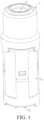
FIG. 1 is a three-dimensional schematic structural diagram of a diverging vaporization module of a vaporization device according to an embodiment of the present invention; -
FIG. 2 is a three-dimensional schematic structural diagram of the diverging vaporization module inFIG. 1 viewed from another angle; -
FIG. 3 is a schematic cross-sectional view of the diverging vaporization module inFIG. 1 ; and -
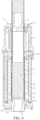
FIG. 4 is a schematic cross-sectional view of an accommodating cavity of the diverging vaporization module inFIG. 3 with a vaporizable medium inserted therein. - In order to have a clearer understanding of the technical features, the objectives, and the effects of the present invention, specific implementations of the present invention are now illustrated in detail with reference to the accompanying drawings.
- As shown in
FIG. 1 to FIG. 3 , a diverging vaporization module 1 of an embodiment of the present invention is provided. The diverging vaporization module 1 is configured for use in an electronic vaporization device to vaporize a flavor aerosol-forming matrix, such as a flavor cartridge or other solid aerosol-forming matrix. The electronic vaporization device is further configured to vaporize a liquid aerosol-forming matrix. Aerosol formed after the electronic vaporization device vaporizes the liquid aerosol-forming matrix flows into the diverging vaporization module to vaporize the flavor aerosol-forming matrix. - The diverging vaporization module 1 includes an
accommodating cavity 11; aheating component 12, athermal insulation component 13, and a divergingairway 14 arranged outside theaccommodating cavity 11; and an air inlet A and an air outlet B respectively configured for air intake and exhaust. The air outlet B is generally connected to a smoke outlet. After the diverging vaporization module 1 is installed in the electronic vaporization device, theaccommodating cavity 11 is configured to accommodate an aerosol-formingmatrix 2, theheating component 12 is configured to heat the aerosol-formingmatrix 2 accommodated in theaccommodating cavity 11, so as to vaporize an effective substance in the aerosol-formingmatrix 2. The effective substance may be nicotine or other pharmacological ingredient, etc. Thethermal insulation component 13 is arranged on an outer side of theheating component 12 and is configured to isolate heat generated by theheating component 12, so as to maintain the heating efficiency and prevent the temperature of a shell of the electronic vaporization device from being excessively high to affect the user experience. Further, the isolation of the heat by thethermal insulation component 13 can also avoid affecting the temperature of the aerosol in the divergingairway 14, thereby further improving the taste of the aerosol inhaled by the user. - The air inlet A is respectively in communication with the air inlet ends of the
accommodating cavity 11 and thediverging airway 14. The air outlet B is respectively in communication with the air inlet ends of theaccommodating cavity 11 and thediverging airway 14. When the diverging vaporization module 1 is installed in the electronic vaporization device and the electronic vaporization device is in an operating state, the aerosol formed after the electronic vaporization device vaporizes the liquid aerosol-forming matrix enters from the air inlet A and flows out respectively through theaccommodating cavity 11 and thediverging airway 14. The aerosol flowing through theaccommodating cavity 11 causes the release of an effective flavor substance from a plant-grass like substance such as the aerosol-formingmatrix 2 accommodated in theaccommodating cavity 11, so that the aerosol flowing out from theaccommodating cavity 11 has a flavor. The aerosol with the flavor is mixed with the aerosol formed by the vaporization of the liquid aerosol-forming matrix flowing out from thediverging airway 14, so that a better taste can be obtained, which improves the user experience. - In some embodiments, the air inlet A and the air outlet B are respectively located on two ends of the diverging vaporization module 1. The air inlet A and the air outlet B may be respectively located in the centers of the two ends of the diverging vaporization module 1. As shown in
FIG. 1 to FIG. 3 , from the perspective of projection, the air inlet A and the air outlet B are respectively located in the centers of two cross-sections. In some embodiments, the air inlet A and the air outlet B may also be respectively located on side surfaces (not shown) of the two ends of the diverging vaporization module 1, or the air inlet A and the air outlet B may also be respectively located on side walls (not shown) of theaccommodating cavity 11 of the diverging vaporization module 1. In some embodiments, the air inlet A and the air outlet B are staggered circumferentially, allowing for more heat exchanges between the aerosol which flows in from the air inlet A and the aerosol which flows out from the air outlet B, thereby achieving a richer taste. In practice, the positions of the air inlet A and the air outlet B may be determined according to the specific structure and design of the electronic vaporization device, and is not limited in the present invention as long as the aerosol entering from the air inlet A can flow out respectively through theaccommodating cavity 11 and thediverging airway 14. - In some embodiments, the
heating component 12 surrounds the outer periphery of a side wall of theaccommodating cavity 11. Theheating component 12 may adopt resistive heating, infrared heating, electromagnetic heating, etc. The resistive heating may be realized by wrapping the accommodating cavity by a flexible printed circuit (FPC), or by printing a heating thick film outside theaccommodating cavity 11. In addition, theheating component 12 may also be arranged in segments along an axial direction of theaccommodating cavity 11 to realize segment-wise heating, and so on, which is not limited in the present invention. Theaccommodating cavity 11 may be made of a metal with high thermal conductivity, such as stainless steel. Further, thethermal insulation component 13 surrounds the outer periphery of theheating component 12 to achieve more uniform heating. - In some embodiments, the
diverging airway 14 is located on the outer periphery of thethermal insulation component 13 to prevent interference from the temperature of gas in thediverging airway 14 and the temperature of gas in theaccommodating cavity 11 to affect the temperature of the aerosol in thediverging airway 14. In some other embodiments, thediverging airway 14 may also be arranged between thethermal insulation component 13 and theheating component 12, so that thethermal insulation component 13 can isolate the heat generated by theheating component 12, so as to prevent the temperature of the shell of the electronic vaporization device from being excessively high to affect the user experience. - In some embodiments, an
isolation pipe 15 is further sleeved outside thethermal insulation component 13, ahousing 16 is sleeved outside theisolation pipe 15, and thediverging airway 14 is formed between thehousing 16 and theisolation pipe 15. Such a configuration not only can prevent the gas in thediverging airway 14 from being affected by other devices, but also can prevent the heat from being conducted to the shell, thereby preventing the temperature of the shell from being excessively high to affect the user experience. - In some embodiments, an
air inlet hole 141 and anair outlet hole 142 respectively in communication with the air inlet A and the air outlet B are respectively arranged on the two ends of the divergingairway 14, to allow the gas to flow smoothly. - In some embodiments, pores are provided on a side wall of a container which defines the
accommodating cavity 11, and the diverging vaporization module 1 further includes a flow cavity C in communication with the divergingairway 14 and the air outlet B. The aerosol entering theaccommodating cavity 11 and the aerosol formed by the vaporization of the aerosol-formingmatrix 2 may enter the flow cavity C through the pores, and then mixed in the flow cavity C, to provide a better taste of the aerosol to the user. - In some embodiments, during use, the diverging vaporization module 1 is installed on a vaporizer, so that the air inlet is in communication with an outlet on the vaporizer. The aerosol-forming
matrix 2 is inserted into theaccommodating cavity 11. The aerosol produced by the vaporizer heating the aerosol-formingmatrix 2 flows into the diverging vaporization module 1 through the air inlet A. The aerosol partly enters the divergingairway 14, and partly enters theaccommodating cavity 11 to heat a plant-grass like substance such as the aerosol-formingmatrix 2 in theaccommodating cavity 11, so as to form a mixed aerosol containing an effective substance of the aerosol-formingmatrix 2. - In addition, the
heating component 12 can generate heat to heat the aerosol-formingmatrix 2 after being electrified. Different heating temperatures may be selected to control the amount of effective substance such as nicotine released from the aerosol-formingmatrix 2, to achieve a steadier release of the effective substance in the entire vaporization stage. - It may be understood that, in the embodiment where pores are provided on the side wall of the container which defines the
accommodating cavity 11, the aerosol in theaccommodating cavity 11 flows into the flow cavity C through the pores and is mixed with the aerosol flowing through the diverging airway, so that the mixed aerosol provides a steady amount of effective substance, thereby achieving a better taste. - It may be understood that the diverging vaporization module 1 may be used in combination with a specially designed aerosol-forming
matrix 2, so as to achieve diverging and mixing.FIG. 4 is a schematic diagram of the diverging vaporization module 1 installed in an electronic vaporization device and accommodating the aerosol-formingmatrix 2 according to an embodiment of the present invention. Circulation holes 21 for the gas in the divergingairway 14 to flow out are provided on a side wall of the aerosol-formingmatrix 2. The gas flowing out from the divergingairway 14 and the gas flowing through theaccommodating cavity 11 are mixed in the aerosol-formingmatrix 2 to form a mixed aerosol. Since the temperatures and the concentrations of the aerosol flows mixed in the aerosol-formingmatrix 2 are different, a negative pressure is formed in the aerosol-formingmatrix 2, so that the effective substance such as nicotine can be better carried. In addition, the mixing of the two flows can harmonize the taste and make the taste smoother. - Further, the circulation holes 21 are distributed along a circumferential direction of the aerosol-forming
matrix 2, so that the gas flowing out from divergingairway 14 enters a cigarette 17 from a circumference of the aerosol-formingmatrix 2, making the mixing more uniform. - Further, the diverging vaporization module 1 may further include a
temperature control assembly 18 configured to control a temperature of theheating component 12. A target temperature of heating may be adjusted according to the user's needs. Thetemperature control assembly 18 may include only a signal receiver, which is configured to receive a preset signal from a battery end for control, or receive a set temperature inputted by the user through keys or a screen after being powered by a battery. - It may be understood that an adjusting component may be arranged additionally on the air inlet end of the diverging vaporization module 1. The adjusting component is configured to adjust an amount of the aerosol flowing through the diverging
airway 14 and an amount of the aerosol flowing through theaccommodating cavity 11. By adjusting the amount of the aerosol generated from the plant-grass like substance such as the aerosol-formingmatrix 2, the aerosol flavor can be adjusted to better satisfy the user's needs. - According to the embodiments of the diverging vaporization module of the present invention, vapor produced by an electronic vaporization device partly flows into the accommodating cavity through the air inlet at the bottom of the accommodating cavity so as to vaporize a plant-grass like substance such as the aerosol-forming matrix in the accommodating cavity, and partly flows out of the air outlet through the diverging airway. The two parts of the aerosol are mixed for the user to inhale. The mixed aerosol provides a steady amount of effective substance and tastes good, which improves the user experience.
- It may be understood that the foregoing technical features can be used in any combination without limitation.
- The foregoing descriptions are embodiments of this application, and the scope of this application is not limited thereto. All equivalent structure or process changes made according to the content of this specification and the accompanying drawings in this application or by directly or indirectly applying this application in other related technical fields shall fall within the protection scope of this application.
- While the invention has been illustrated and described in detail in the drawings and foregoing description, such illustration and description are to be considered illustrative or exemplary and not restrictive. It will be understood that changes and modifications may be made by those of ordinary skill within the scope of the following claims. In particular, the present invention covers further embodiments with any combination of features from different embodiments described above and below. Additionally, statements made herein characterizing the invention refer to an embodiment of the invention and not necessarily all embodiments.
- The terms used in the claims should be construed to have the broadest reasonable interpretation consistent with the foregoing description. For example, the use of the article "a" or "the" in introducing an element should not be interpreted as being exclusive of a plurality of elements. Likewise, the recitation of "or" should be interpreted as being inclusive, such that the recitation of "A or B" is not exclusive of "A and B," unless it is clear from the context or the foregoing description that only one of A and B is intended. Further, the recitation of "at least one of A, B and C" should be interpreted as one or more of a group of elements consisting of A, B and C, and should not be interpreted as requiring at least one of each of the listed elements A, B and C, regardless of whether A, B and C are related as categories or otherwise. Moreover, the recitation of "A, B and/or C" or "at least one of A, B or C" should be interpreted as including any singular entity from the listed elements, e.g., A, any subset from the listed elements, e.g., A and B, or the entire list of elements A, B and C.
Claims (12)
- A diverging vaporization module, comprising:an accommodating cavity (11) configured to accommodate aerosol-forming matrix (2);a heating component (12), a thermal insulation component (13), and a diverging airway (14) that are arranged outside the accommodating cavity (11); andan air inlet (A) and an air outlet (B) respectively configured for air intake and exhaust,wherein the air inlet (A) is respectively in communication with the air inlet ends of the accommodating cavity (11) and the diverging airway (14), and the air outlet (B) is respectively in communication with the air outlet ends of the accommodating cavity (11) and the diverging airway (14), so that aerosol entering the air inlet (A) flows out through the accommodating cavity (11) and the diverging airway (14).
- The diverging vaporization module of claim 1, wherein the air inlet (A) and the air outlet (B) are respectively located on the two ends of the diverging vaporization module (1).
- The diverging vaporization module of claim 1, further comprising:
a temperature control assembly (18) configured to control the temperature of the heating component (12). - The diverging vaporization module of claim 1, wherein the heating component (12) surrounds the outer periphery of the side wall of the accommodating cavity (11).
- The diverging vaporization module of claim 4, wherein the thermal insulation component (13) surrounds the outer periphery of the heating component (12).
- The diverging vaporization module of any one of claims 1 to 5, wherein the diverging airway (14) is located on the outer periphery of the thermal insulation component (13).
- The diverging vaporization module of claim 6, wherein an isolation pipe (15) is sleeved outside the thermal insulation component (13), a housing (16) is sleeved outside the isolation pipe (15), and the diverging airway (14) is formed between the housing (16) and the isolation pipe (15).
- The diverging vaporization module of claim 7, wherein an air inlet hole (141) and an air outlet hole (142) respectively in communication with the air inlet (A) and the air outlet (B) are respectively provided on the two ends of the diverging airway (14).
- The diverging vaporization module of claim 8, wherein the air inlet hole (141) and the air outlet hole (142) on the two ends of the diverging airway (14) are staggered circumferentially.
- The diverging vaporization module of claim 8, further comprising:
a flow cavity (C) in communication with the diverging airway (14) and the air outlet (B). - The diverging vaporization module of any one of claims 1 to 5, wherein an adjusting component is arranged on the air inlet end of the diverging vaporization module (1), to adjust the amount of aerosol flowing through the diverging airway (14) and the amount of aerosol flowing through the accommodating cavity (11).
- A vaporization device, comprising:the diverging vaporization module (1) of any one of claims 1 to 11; anda vaporizer matching with the diverging vaporization module (1);wherein aerosol heated and discharged by the vaporizer flows into the diverging vaporization module (1) through the air inlet (A).
Applications Claiming Priority (1)
| Application Number | Priority Date | Filing Date | Title |
|---|---|---|---|
| CN202111619942.4A CN114223953B (en) | 2021-12-27 | 2021-12-27 | Atomization device and split flow atomization module |
Publications (2)
| Publication Number | Publication Date |
|---|---|
| EP4212036A2 true EP4212036A2 (en) | 2023-07-19 |
| EP4212036A3 EP4212036A3 (en) | 2023-10-18 |
Family
ID=80764032
Family Applications (1)
| Application Number | Title | Priority Date | Filing Date |
|---|---|---|---|
| EP22213016.3A Pending EP4212036A3 (en) | 2021-12-27 | 2022-12-13 | Vaporization device and module with diverging flowpath |
Country Status (5)
| Country | Link |
|---|---|
| US (1) | US20230200449A1 (en) |
| EP (1) | EP4212036A3 (en) |
| JP (1) | JP7524271B2 (en) |
| KR (1) | KR102809447B1 (en) |
| CN (1) | CN114223953B (en) |
Families Citing this family (1)
| Publication number | Priority date | Publication date | Assignee | Title |
|---|---|---|---|---|
| CN115997984A (en) * | 2023-01-09 | 2023-04-25 | 深圳麦克韦尔科技有限公司 | Atomization device |
Family Cites Families (14)
| Publication number | Priority date | Publication date | Assignee | Title |
|---|---|---|---|---|
| CN102628587B (en) * | 2012-04-23 | 2014-10-08 | 王兔林 | Phase change heating heat machine and heating method by using phase change heating heat machine |
| WO2014110119A1 (en) | 2013-01-08 | 2014-07-17 | L. Perrigo Company | Electronic cigarette |
| DE202014001718U1 (en) * | 2014-02-27 | 2015-05-28 | Xeo Holding GmbH | smoking device |
| AU2015379291B2 (en) | 2015-01-26 | 2019-06-06 | Japan Tobacco Inc. | Non-combustion type flavor inhaler, flavor source unit, and method for manufacturing member used in a non-combustion type flavor inhaler |
| EP3476230B1 (en) * | 2016-06-28 | 2020-08-05 | Changzhou Jwei Intelligent Technology Co., Ltd. | Atomizer and electronic cigarette |
| DE102016125180A1 (en) * | 2016-12-21 | 2018-06-21 | Hauni Maschinenbau Gmbh | An evaporator unit for an inhaler and method for controlling an evaporator unit |
| DE102017111435B4 (en) * | 2017-05-24 | 2018-12-06 | Hauni Maschinenbau Gmbh | An evaporator unit for an inhaler and method for controlling an evaporator unit |
| DE102017123172A1 (en) | 2017-10-05 | 2019-04-11 | Xeo Holding GmbH | smoking device |
| KR102875241B1 (en) | 2019-07-04 | 2025-10-24 | 필립모리스 프로덕츠 에스.에이. | Induction heating array having gas-permeable compartmentalized induction heating elements |
| CN111588096A (en) * | 2020-06-19 | 2020-08-28 | 浙江育康清生物医药有限公司 | Portable electronic smoke sprayer |
| CN112493547A (en) | 2020-12-07 | 2021-03-16 | 深圳麦克韦尔科技有限公司 | Electronic atomization device |
| CN113598426A (en) * | 2021-07-30 | 2021-11-05 | 深圳麦克韦尔科技有限公司 | Heating module and electronic atomization device |
| CN113679108B (en) * | 2021-08-18 | 2024-10-22 | 深圳麦克韦尔科技有限公司 | Electronic atomizing device |
| CN216875011U (en) * | 2021-12-27 | 2022-07-05 | 深圳麦克韦尔科技有限公司 | Atomizing device and reposition of redundant personnel atomizing module |
-
2021
- 2021-12-27 CN CN202111619942.4A patent/CN114223953B/en active Active
-
2022
- 2022-09-27 KR KR1020220122906A patent/KR102809447B1/en active Active
- 2022-11-01 JP JP2022175438A patent/JP7524271B2/en active Active
- 2022-12-13 EP EP22213016.3A patent/EP4212036A3/en active Pending
- 2022-12-23 US US18/087,995 patent/US20230200449A1/en active Pending
Also Published As
| Publication number | Publication date |
|---|---|
| KR20230099626A (en) | 2023-07-04 |
| KR102809447B1 (en) | 2025-05-19 |
| US20230200449A1 (en) | 2023-06-29 |
| JP7524271B2 (en) | 2024-07-29 |
| JP2023097352A (en) | 2023-07-07 |
| EP4212036A3 (en) | 2023-10-18 |
| CN114223953B (en) | 2025-06-17 |
| CN114223953A (en) | 2022-03-25 |
Similar Documents
| Publication | Publication Date | Title |
|---|---|---|
| US11889862B2 (en) | Apparatus and system for generating aerosols | |
| US9986764B2 (en) | Vaporizer | |
| US20200107585A1 (en) | Heating element | |
| CN207653564U (en) | Electronic cigarette | |
| JP5877066B2 (en) | Improved spray electronic cigarette | |
| JP7405906B2 (en) | electronic atomization device | |
| CN211721878U (en) | Aerosol generating system | |
| US20260115405A1 (en) | System and Method for On-Demand Near-Patient Humidification | |
| JP2012517229A5 (en) | ||
| EP4069019A1 (en) | An aerosol generation device having a heating chamber with a thermal guard | |
| CN209234986U (en) | Smoke grenade and electronic cigarette | |
| KR102806060B1 (en) | Seasoning component and electronic atomization device | |
| US20230200449A1 (en) | Vaporization device and diverging vaporization module | |
| JP7482942B2 (en) | Heating module and electronic atomizer | |
| US20240066257A1 (en) | Humidifying a gas flow stream | |
| US20240298705A1 (en) | Atomizing device and electronic cigarette | |
| CN209235002U (en) | Atomizer and electronic cigarette | |
| CN216875011U (en) | Atomizing device and reposition of redundant personnel atomizing module | |
| US20240065326A1 (en) | Vaporizer and electronic vaporization device | |
| EP4205576A1 (en) | Aerosol flavor adjusting device and vaporization device | |
| CN112790429A (en) | Horizontal ceramic heat conductors, heating elements, electronic atomizers, and electronic atomizers | |
| WO2022116050A1 (en) | Atomizer and electronic atomizing device | |
| CN221449879U (en) | Aerosol Generating Device | |
| KR102781789B1 (en) | Porous absorbent unit for absorbing and accommodating aerosol-forming substrate | |
| US20250057229A1 (en) | Aerosol delivery system |
Legal Events
| Date | Code | Title | Description |
|---|---|---|---|
| PUAI | Public reference made under article 153(3) epc to a published international application that has entered the european phase |
Free format text: ORIGINAL CODE: 0009012 |
|
| STAA | Information on the status of an ep patent application or granted ep patent |
Free format text: STATUS: THE APPLICATION HAS BEEN PUBLISHED |
|
| AK | Designated contracting states |
Kind code of ref document: A2 Designated state(s): AL AT BE BG CH CY CZ DE DK EE ES FI FR GB GR HR HU IE IS IT LI LT LU LV MC ME MK MT NL NO PL PT RO RS SE SI SK SM TR |
|
| PUAL | Search report despatched |
Free format text: ORIGINAL CODE: 0009013 |
|
| AK | Designated contracting states |
Kind code of ref document: A3 Designated state(s): AL AT BE BG CH CY CZ DE DK EE ES FI FR GB GR HR HU IE IS IT LI LT LU LV MC ME MK MT NL NO PL PT RO RS SE SI SK SM TR |
|
| RIC1 | Information provided on ipc code assigned before grant |
Ipc: A24F 40/20 20200101ALN20230911BHEP Ipc: A24F 40/485 20200101AFI20230911BHEP |
|
| STAA | Information on the status of an ep patent application or granted ep patent |
Free format text: STATUS: REQUEST FOR EXAMINATION WAS MADE |
|
| 17P | Request for examination filed |
Effective date: 20240109 |
|
| RBV | Designated contracting states (corrected) |
Designated state(s): AL AT BE BG CH CY CZ DE DK EE ES FI FR GB GR HR HU IE IS IT LI LT LU LV MC ME MK MT NL NO PL PT RO RS SE SI SK SM TR |
|
| RAP3 | Party data changed (applicant data changed or rights of an application transferred) |
Owner name: SHENZHEN SMOORE TECHNOLOGY LIMITED |
|
| RAP3 | Party data changed (applicant data changed or rights of an application transferred) |
Owner name: SHENZHEN SMOORE TECHNOLOGY LIMITED |
|
| STAA | Information on the status of an ep patent application or granted ep patent |
Free format text: STATUS: EXAMINATION IS IN PROGRESS |
|
| 17Q | First examination report despatched |
Effective date: 20260408 |