EP4211824B1 - Wireless telecommunications network - Google Patents
Wireless telecommunications network Download PDFInfo
- Publication number
- EP4211824B1 EP4211824B1 EP21798356.8A EP21798356A EP4211824B1 EP 4211824 B1 EP4211824 B1 EP 4211824B1 EP 21798356 A EP21798356 A EP 21798356A EP 4211824 B1 EP4211824 B1 EP 4211824B1
- Authority
- EP
- European Patent Office
- Prior art keywords
- neural network
- irs
- wireless signal
- bit sequence
- node
- Prior art date
- Legal status (The legal status is an assumption and is not a legal conclusion. Google has not performed a legal analysis and makes no representation as to the accuracy of the status listed.)
- Active
Links
Images


Classifications
-
- H—ELECTRICITY
- H04—ELECTRIC COMMUNICATION TECHNIQUE
- H04B—TRANSMISSION
- H04B17/00—Monitoring; Testing
- H04B17/30—Monitoring; Testing of propagation channels
- H04B17/391—Modelling the propagation channel
- H04B17/3913—Predictive models, e.g. based on neural network models
-
- H—ELECTRICITY
- H04—ELECTRIC COMMUNICATION TECHNIQUE
- H04B—TRANSMISSION
- H04B7/00—Radio transmission systems, i.e. using radiation field
- H04B7/14—Relay systems
- H04B7/15—Active relay systems
- H04B7/155—Ground-based stations
-
- H—ELECTRICITY
- H04—ELECTRIC COMMUNICATION TECHNIQUE
- H04B—TRANSMISSION
- H04B17/00—Monitoring; Testing
- H04B17/30—Monitoring; Testing of propagation channels
- H04B17/391—Modelling the propagation channel
- H04B17/3912—Simulation models, e.g. distribution of spectral power density or received signal strength indicator [RSSI] for a given geographic region
-
- H—ELECTRICITY
- H04—ELECTRIC COMMUNICATION TECHNIQUE
- H04B—TRANSMISSION
- H04B7/00—Radio transmission systems, i.e. using radiation field
- H04B7/02—Diversity systems; Multi-antenna system, i.e. transmission or reception using multiple antennas
- H04B7/04—Diversity systems; Multi-antenna system, i.e. transmission or reception using multiple antennas using two or more spaced independent antennas
- H04B7/04013—Intelligent reflective surfaces
-
- H—ELECTRICITY
- H04—ELECTRIC COMMUNICATION TECHNIQUE
- H04L—TRANSMISSION OF DIGITAL INFORMATION, e.g. TELEGRAPHIC COMMUNICATION
- H04L25/00—Baseband systems
- H04L25/02—Details ; arrangements for supplying electrical power along data transmission lines
- H04L25/0202—Channel estimation
- H04L25/0204—Channel estimation of multiple channels
Definitions
- the present invention relates to a wireless telecommunications network having an intelligent reflective surface.
- a wireless signal being transmitted between a transmitter and receiver generally degrades due to interference from other wireless signals and/or other physical phenomena (e.g. fading and blockage). This has generally been addressed by improving the transmission characteristics (e.g. higher power transmissions or repeaters) or transmission processing techniques (e.g. more robust modulation schemes).
- An emerging concept in wireless telecommunications is the concept of a reconfigurable propagation environment, or "smart radio environment", which may improve the transmission quality.
- This may be achieved by use of a surface of electromagnetic material, often known as an Intelligent Reflective Surface (IRS), which may be operated so as to apply a change to an incident wireless signal, such as a change in phase, amplitude, frequency and polarisation, so as to improve the transmission quality between the transmitter and the receiver.
- IFS Intelligent Reflective Surface
- the receiver may receive a wireless signal in a direct path between the transmitter and receiver or via one or more reflected signals.
- the receiver may not be able to successfully receive either of the direct or reflected signals from the transmitter (that is, the receiver is in a "not-spot").
- a reflected signal between the transmitter and receiver e.g. reflected off a nearby building
- degrades another received signal e.g. the direct signal
- Both of these scenarios can be improved by the introduction of an IRS.
- the IRS may act upon the reflected signal so that it may be successfully received at the receiver.
- the IRS may phase shift the incident wireless signal so that it constructively interferes with the direct signal between the transmitter and receiver. The IRS may therefore be used to improve transmission quality between the transmitter and the receiver.
- an IRS may be a cost effective solution to improving transmission quality compared to alternative solutions, such as by increasing access point density, as IRSs are nearly passive and easy to deploy.
- the IRS controller must calculate the change (e.g. phase shift) to apply to an incident wireless signal in order to improve transmission quality at the receiver.
- Change e.g. phase shift
- IRS includes large intelligent surface, large intelligent metasurface, programmable metasurface, reconfigurable metasurface, smart reflect-arrays, reconfigurable intelligent surface, software-defined surface, and passive intelligent surface.
- the term "reconfigurable” is often used to indicate that the angle of reflection can be configured regardless of the angle of incidence.
- the termination condition may be that the calculated loss has converged for a plurality of iterations.
- the termination condition may be that the calculated loss has converged at or near a minimum value for a plurality of iterations.
- the loss may be calculated based on a cross-entropy loss function.
- the method may further comprise the steps of: vi) determining that a reconfiguration condition has been met; and vii) in response to the determination that the reconfiguration condition has been met, repeating steps i) to v).
- the method may be performed by the transmitting node.
- a computer program comprising instructions which, when the program is executed by a computer, cause the computer to carry out the steps of the first aspect of the invention.
- the computer program may be provided on a computer readable carrier medium.
- the node may be the transmitting node.
- the node may be part of a wireless telecommunications network.
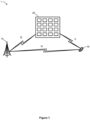
- the wireless telecommunications system is a cellular telecommunications network 1 having a base station 10, an Intelligent Reflective Surface (IRS) 20, and a User Equipment (UE) 30.
- the base station 10 utilises M antennas
- the IRS 20 includes N reflective elements
- the UE 30 includes K antennas .
- both M and K are greater than one such that the wireless telecommunications system operates as a Multiple-Input Multiple-Output (MIMO) system.
- MIMO Multiple-Input Multiple-Output
- a first communications path between the base station 10 and UE 30 includes a direct channel, identified as channel H in Figure 1
- a second communications path between the base station 10 and UE 30 includes a first channel between the base station 10 and IRS 20, identified as channel G in Figure 1 , and a second channel between the IRS 20 and UE 30, identified as channel F in Figure 1
- the first channel of the second communications path represents a signal transmitted by the base station 10 that is incident on the IRS 20
- the second channel of the second communications path represents a reflection of the incident signal that is reflected off the IRS 20 and received by the UE 30.
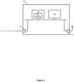
- the base station 10 includes a first communications interface 11 that is connectable to an antenna for transmitting and receiving wireless signals, a processor 13, memory 15, and a second communications interface 17 that is connectable to a wired backhaul connection to a core network (not shown).
- the processor 13 implements a base station neural network which, for a given input bit sequence, b, outputs a signal, x, to be transmitted by the antenna.
- the training and operational phases of the base station neural network in particular the determination of the weights, W BS , of the base station neural network, are described below.
- the base station 10 is configured to determine, using a channel estimation scheme, the Channel State Information (CSI) for channel H between the base station 10 and UE 30 of the direct communications path, the CSI for channel F between the base station 10 and IRS 20 of the second communications path, and the CSI for channel G between the IRS 20 and UE 30 of the second communications path.
- CSI Channel State Information
- An example channel estimation scheme that may be used by the base station 10 is based on Minimum Mean Squared Error (MMSE), as proposed in "Intelligent reflecting surface assisted wireless communication: Modeling and channel estimation," by Q.-U.-A. Nadeem, A. Kammoun, A. Chaaban, M. Debbah, and M.-S. Alouini.
- MMSE Minimum Mean Squared Error
- the IRS 20 includes a set of reflective elements 21 and a processor 23 for causing each reflective element of the set of reflective elements 21 to apply a phase shift to an incident wireless signal according to the reflection coefficient of the phase shift matrix element corresponding to that reflective element.
- the determination of the phase shift matrix is also described below.
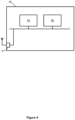
- the UE 30 includes a first communications interface 31 which is connectable to an antenna for transmitting and receiving wireless signals, a processor 33, and memory 35.
- the processor 33 implements a UE neural network which, for a given input wireless signal, y, outputs an output bit sequence, b ⁇ , for higher layer processing.
- the UE neural network is implemented based on the following layout: Table 2: Layout of the UE neural network in the UE 30 Layer Output Dimensions Input K Complex to Real 2K Dense + ReLU 2M Dense + ReLU 2M Dense + Sigmoid k
- the base station's processor 13 is further configured to operate a simulation environment (on a suitably configured Field-Programmable Gate Array (FPGA)) for simulating a transmission of a wireless signal between the base station 10 and UE 30 via the IRS 20. Accordingly, the processor 13 may determine:
- the simulation environment is further configured to calculate a loss (i.e. the degree of difference) between an input bit sequence, b, and the simulated output bit sequence, b ⁇ , following simulation of the transmission of that input bit sequence, hereinafter denoted loss(b, b ⁇ ) .
- loss(b, b ⁇ ) is calculated using a cross entropy function.
- the processor 13 is further configured to model the system and update the values for the base station neural network, the UE neural network, and the phase shift matrix (to be used in subsequent simulations and/or the base station 10, IRS 20 and UE 30).
- the system is modelled as an autoencoder in which a first component models the base station neural network (as used by the base station and in the simulation, based on table 1 above), a second component models the UE neural network (as used by the UE neural network and in the simulation, based on table 2 above) and a third component models the operation of the IRS 20.
- the third component of the autoencoder is based on the following layout: Table 3: Layout of the third component of the autoencoder modelling the phase shift matrix Layer Output dimensions Input 2M Normalization (to meet IRS 20 hardware constraints
- ⁇ W BS t is the gradient of W BS t to the calculated loss, loss(b, b ⁇ ) of the simulated transmission
- ⁇ t is the gradient of ⁇ t to the calculated loss
- ⁇ W UE t is the gradient of W UE t to the calculated loss, loss ( b, b ⁇ ) of the simulated transmission.
- Keras An example processing environment that may be used is provided by Keras, available at https://keras.io, which provides suitable deep learning libraries for this embodiment.
- the base station 10 determines the channel matrix, H, representing the direct channel between the base station 10 and UE 30 of the first communications path, the channel matrix, G, representing the channel between the base station 10 and IRS 20 of the second communications path, and the channel matrix, F, representing the channel between the IRS 20 and UE 30 of the second communications path.
- the base station 10 uses the MMSE channel estimation scheme to determine these channel matrices.
- the base station 10 further determines a count, N, of reflective elements in the set of reflective elements of the IRS 20.
- the count, N may be known to the base station 10 (e.g. as a predetermined parameter) or may be reported to the base station 10 as part of the channel feedback.
- the base station 10 configures its simulation environment so that it may simulate a transmission of a wireless signal from the base station 10 to the UE 30, via the IRS 20, based on this data.
- the processor 13 configures an initial state for the base station neural network based on an initial set of weights, W BS 0 , an initial phase matrix ⁇ ° based on the count, N, of reflective elements in the set of reflective elements, and an initial state for the UE neural network based on an initial set of weights, W UE 0 .
- These initial parameters may be generated by Xavier (for example, using the technique described in " Understanding the difficulty of training deep feedforward neural networks.”, X. Glorot and Y. Bengio, Journal of Machine Learning Research, vol. 9, pp.
- the processor 13 further establishes a noise vector, n, for the simulation.
- step S107 a transmission between the base station 10 and UE 30, via the IRS 20, is simulated using the current simulation environment (which, in this first iteration of this method, is in its initial state as described in step S105 above) for a training bit sequence, b.
- the simulation environment determines an output bit sequence, b ⁇ , for this training bit sequence, b.
- Step S107 is repeated for a plurality of training bit sequences, each determining an output bit sequence for each training bit sequence.
- step S109 the base station 10 calculates the loss, loss ( b,b ⁇ ) , between each output bit sequence, b ⁇ , and corresponding training bit sequence, b, and further calculates an average loss, loss av , of all these calculated losses.
- step S111 the base station 10 determines whether the average loss, loss av , has converged.
- the average loss, loss av converges when its value in the current iteration does not deviate from its value in the previous i iterations (in which i is a number greater than or equal to 1) by a predetermined amount. In this first iteration, there are no previous iterations to compare the average loss, loss av , to and so the process continues to step S113. The process following a positive determination that the average loss, loss av , has converged will be described later in the description.
- step S113 the base station 10 updates the base station neural network weights, the phase matrix, and the UE neural network weights based on the average loss, loss av , from step S109 (as described above).
- step S115 the base station 10 reconfigures its simulation environment so that it may simulate a transmission of a wireless signal from the base station 10 to the UE 30, via the IRS 20, based on the updated values for the base station neural network weights, W BS t + 1 (calculated in step S113 of the current iteration), on the updated values for the phase shift matrix ⁇ t +1 (calculated in step S113 of the current iteration), and on the updated values for UE neural network weights, W UE t + 1 (calculated in step S113 of the current iteration).
- step S107 a further plurality of transmissions between the base station 10 and UE 30, via the IRS 20, are simulated using the reconfigured simulation environment (as reconfigured in step S115 of the previous iteration) for the plurality of training bit sequences, b.
- the method then proceeds to calculate a new average loss, loss av , in step S109 and determines whether the average loss, loss av , has converged in step S111.
- the method of this embodiment iterates through various configurations of the base station neural network weights, UE neural network weights and phase shift matrix, with each iteration's configuration determined using the BP algorithm based on the previous iteration's average loss, until the average loss converges at its minimum value.
- step S111 the method proceeds to step S117 in which the values for the base station neural network weights, UE neural network weights and phase matrix (as used in the final iteration) are deployed in the network 1.
- the base station's processor 13 configures its base station neural network weights according to the values used in the final iteration, transmits values for the phase shift matrix to the IRS 20, and transmits values for the UE neural network weights to the UE 30.
- the IRS 20 configures its phase shift matrix according to these received values
- the UE 30 configures its UE neural network weights according to these received values.
- step S117 all downlink communications from the base station 10 to the UE 30, via the IRS 20, utilise the base station neural network, phase shift matrix, and UE neural network configured with these values.
- step S119 the base station 10 determines whether a reconfiguration trigger condition has been met.
- there are two reconfiguration trigger conditions 1) that a period of 10ms has elapsed since the previous performance of the algorithm, and 2) the CSI of one or more of the channels has deviated by a particular threshold (e.g. 10%).
- the base station 10 may therefore be configured to continually monitor the CSI of the channels, e.g. every 1ms, to determine if this second reconfiguration trigger condition has been met.
- the process loops back to step S101.
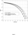
- the graph of Figure 6 illustrates simulation results of transmissions at different Signal to Noise Ratios (SNRs) and the bit error rate of that transmission.
- the simulation is performed for three different scenarios, 1) transmissions from the base station 10 to the UE 30 without the IRS 20, 2) transmissions from the base station 10 to the UE 30 with the IRS 20, in which the determination of the precoding vector of the base station 10, determination of the phase shift matrix of the IRS 20, and the signal detection method at the UE 30 are all based on conventional techniques, and 3) transmissions from the base station 10 to the UE 30 with the IRS 20, based on the above embodiment of the method of present invention. It is shown that the above embodiment results in comparatively lower BER, for a given SNR, when implementing the above embodiment compared to the two other scenarios, with greater gains at higher SNRs.
- IRS is used in the above embodiment, but the skilled person will understand that any equivalent device that may reflect an incident wireless signal and apply a phase shift to the incident wireless signal may be used.
- An equivalent device may be known as a large intelligent surface, a large intelligent metasurface, a programmable metasurface, a reconfigurable metasurface, a smart reflect-arrays, a reconfigurable intelligent surface, a software-defined surface, and a passive intelligent surface.
- the base station neural network, UE neural network and phase shift matrix of the IRS are reconfigured by a BP algorithm so as to minimise an average loss between a plurality of training bit sequences input at the base station and the corresponding bit sequences output at the UE, wherein the average loss is based on a cross-entropy function.
- a BP algorithm so as to minimise an average loss between a plurality of training bit sequences input at the base station and the corresponding bit sequences output at the UE, wherein the average loss is based on a cross-entropy function.
- MSE Mean Squared Error
- the base station 10, IRS 20 and UE 30 may be similarly configured for uplink communications.
- the base station 10, IRS 20 and UE 30 may be configured for both downlink and uplink communications using a duplexing method, such as Time Division Duplex (TDD) or Frequency Division Duplex (FDD), in which the base station 10 and UE 30 use distinct neural networks for downlink and uplink communications and the IRS uses distinct phase shift matrices for downlink and uplink communications.
- TDD Time Division Duplex
- FDD Frequency Division Duplex
- the phase shift matrix for uplink communications may be transformed from the phase shift matrix for downlink communications, and vice versa.
- the base station's processor simulation environment is able to simulate the received signal, y, as received by the UE 30 based on the simulated output, x, of the base station neural network, the channel matrix, H, representing the direct channel between the base station 10 and UE 30 of the first communications path, the channel matrix, G, representing the channel between the base station 10 and IRS 20 of the second communications path, the channel matrix, F, representing the channel between the IRS 20 and UE 30 of the second communications path, the phase matrix, ⁇ , of the IRS 20, and the noise vector, n.
- the simulation is further based on a simulated channel fading.
- C 0 is a frequency dependent constant value
- d is the distance between the transmitter and receiver
- neural networks are non-essential, and other implementations are possible.
- implementation in a cellular telecommunications network is non-essential, and that the above embodiment may be applied to other forms of wireless telecommunications network.
- any other node including a centralised entity, may perform the method and send update messages to the transmitting node, IRS and receiving node to update their configurations.
Landscapes
- Engineering & Computer Science (AREA)
- Computer Networks & Wireless Communication (AREA)
- Signal Processing (AREA)
- Physics & Mathematics (AREA)
- Electromagnetism (AREA)
- Artificial Intelligence (AREA)
- Evolutionary Computation (AREA)
- Spectroscopy & Molecular Physics (AREA)
- Power Engineering (AREA)
- Mobile Radio Communication Systems (AREA)
- Transmitters (AREA)
Description
- The present invention relates to a wireless telecommunications network having an intelligent reflective surface.
- In wireless telecommunications, a wireless signal being transmitted between a transmitter and receiver generally degrades due to interference from other wireless signals and/or other physical phenomena (e.g. fading and blockage). This has generally been addressed by improving the transmission characteristics (e.g. higher power transmissions or repeaters) or transmission processing techniques (e.g. more robust modulation schemes). An emerging concept in wireless telecommunications is the concept of a reconfigurable propagation environment, or "smart radio environment", which may improve the transmission quality. This may be achieved by use of a surface of electromagnetic material, often known as an Intelligent Reflective Surface (IRS), which may be operated so as to apply a change to an incident wireless signal, such as a change in phase, amplitude, frequency and polarisation, so as to improve the transmission quality between the transmitter and the receiver.
- In a conventional system having only a transmitter and receiver, the receiver may receive a wireless signal in a direct path between the transmitter and receiver or via one or more reflected signals. In a first scenario, the receiver may not be able to successfully receive either of the direct or reflected signals from the transmitter (that is, the receiver is in a "not-spot"). In a second scenario, a reflected signal between the transmitter and receiver (e.g. reflected off a nearby building) degrades another received signal (e.g. the direct signal) by destructive interference. Both of these scenarios can be improved by the introduction of an IRS. In the first scenario where the receiver cannot receive either the direct or reflected signals from the transmitter, the IRS may act upon the reflected signal so that it may be successfully received at the receiver. Furthermore, in the second scenario, the IRS may phase shift the incident wireless signal so that it constructively interferes with the direct signal between the transmitter and receiver. The IRS may therefore be used to improve transmission quality between the transmitter and the receiver.
- Furthermore, an IRS may be a cost effective solution to improving transmission quality compared to alternative solutions, such as by increasing access point density, as IRSs are nearly passive and easy to deploy. In practical implementations, the IRS controller must calculate the change (e.g. phase shift) to apply to an incident wireless signal in order to improve transmission quality at the receiver. Existing research tends to focus on enhancing capacity or energy saving.
- Alternative names for the IRS include large intelligent surface, large intelligent metasurface, programmable metasurface, reconfigurable metasurface, smart reflect-arrays, reconfigurable intelligent surface, software-defined surface, and passive intelligent surface. The term "reconfigurable" is often used to indicate that the angle of reflection can be configured regardless of the angle of incidence.
- Article "Deep Learning for Large Intelligent Surfaces in Millimeter Wave and Massive MIMO Systems", Taha et al., 2019 IEEE Global Communications Conference, proposes a Large Intelligent Surface (LIS) architecture where all LIS elements are passive except for a few elements that are active. A deep learning based solution is disclosed where the LIS learns how to optimally interact with an incident signal given only the channels at the active elements.
- Article "Unsupervised Learning for Passive Beamforming", Jiabao Gao et al., Cornell University Library, discloses a deep learning approach for passive beamforming design in Reconfigurable Intelligent Surface assisted systems.
- International patent application publication no.
2019/038693 A1 discloses methods and apparatus for training a neural network to recover a codeword of a Forward Error Correction (FEC) code. - According to a first aspect of the invention, there is provided a method as claimed in Claim 1.
- The termination condition may be that the calculated loss has converged for a plurality of iterations. The termination condition may be that the calculated loss has converged at or near a minimum value for a plurality of iterations.
- The loss may be calculated based on a cross-entropy loss function.
- The method may further comprise the steps of: vi) determining that a reconfiguration condition has been met; and vii) in response to the determination that the reconfiguration condition has been met, repeating steps i) to v).
- The method may be performed by the transmitting node.
- According to a second aspect of the invention, there is provided a computer program comprising instructions which, when the program is executed by a computer, cause the computer to carry out the steps of the first aspect of the invention. The computer program may be provided on a computer readable carrier medium.
- According to a third aspect of the invention, there is provided a node as claimed in Claim 9. The node may be the transmitting node. The node may be part of a wireless telecommunications network.
- In order that the present invention may be better understood, embodiments thereof will now be described, by way of example only, with reference to the accompanying drawings in which:
-
Figure 1 is a schematic diagram of a cellular telecommunications network of an embodiment of the present invention; -
Figure 2 is a schematic diagram of a base station of the network ofFigure 1 ; -
Figure 3 is a schematic diagram of an Intelligent Reflective Surface (IRS) of the network ofFigure 1 ; -
Figure 4 is a schematic diagram of a User Equipment (UE) of the network ofFigure 1 ; -
Figure 5 is a flow diagram illustrating an embodiment of a method of the present invention; and -
Figure 6 is a graph illustrating the Bit Error Rate (BER) against Signal-to-Noise Ratio (SNR) for three different scenarios, 1) transmissions from the base station to the UE without the IRS, 2) transmissions from the base station to the UE with the IRS, in which the determination of the precoding vector of the base station, determination of the phase shift matrix of the IRS, and the signal detection method at the UE are all based on conventional techniques, and 3) transmissions from the base station to the UE with the IRS, based on the method ofFigure 5 . - A first embodiment of a wireless telecommunications system will now be described with reference to
Figure 1 . In this embodiment, the wireless telecommunications system is a cellular telecommunications network 1 having abase station 10, an Intelligent Reflective Surface (IRS) 20, and a User Equipment (UE) 30. Thebase station 10 utilises M antennas, the IRS 20 includes N reflective elements, and the UE 30 includes K antennas. In this embodiment, both M and K are greater than one such that the wireless telecommunications system operates as a Multiple-Input Multiple-Output (MIMO) system. - A first communications path between the
base station 10 and UE 30 includes a direct channel, identified as channel H inFigure 1 , and a second communications path between thebase station 10 and UE 30 includes a first channel between thebase station 10 and IRS 20, identified as channel G inFigure 1 , and a second channel between the IRS 20 and UE 30, identified as channel F inFigure 1 . In a downlink communication (that is, from thebase station 10 to the UE 30), the first channel of the second communications path represents a signal transmitted by thebase station 10 that is incident on theIRS 20, and the second channel of the second communications path represents a reflection of the incident signal that is reflected off theIRS 20 and received by the UE 30. The signal received at theUE 30, y, is represented by:
-

-

base station 10 and theUE 30, and superscript T indicates the Hermitian transpose, -

base station 10 and theIRS 20, -

IRS 20 and UE 30, and superscript T indicates the Hermitian transpose, - Θ = diag([β1 ejϕ
1 , β2ejϕ2 , ... , βNejϕN ,]) is the phase shift matrix with each diagonal element representing the reflection coefficient of a reflective element of theIRS 20, in which |βi | ≤ 1 due to the constraints of theIRS 20, - x is the transmitted signal from the
base station 10 and keeps normalized power constraints ∥x∥2 = 1, and -

- As shown in
Figure 2 , thebase station 10 includes afirst communications interface 11 that is connectable to an antenna for transmitting and receiving wireless signals, aprocessor 13, memory 15, and asecond communications interface 17 that is connectable to a wired backhaul connection to a core network (not shown). In this embodiment, theprocessor 13 implements a base station neural network which, for a given input bit sequence, b, outputs a signal, x, to be transmitted by the antenna. In this embodiment, the base station neural network is implemented based on the following layout:Table 1: Layout of the base station neural network in the base station 10Layer Output Dimensions Input k Dense + ReLU 4M Dense + ReLU 4M Dense + Linear 2M Normalization (to meet power constraints ∥x∥2 = 1) 2M Real to Complex M - The training and operational phases of the base station neural network, in particular the determination of the weights, WBS, of the base station neural network, are described below.
- In this embodiment, the
base station 10 is configured to determine, using a channel estimation scheme, the Channel State Information (CSI) for channel H between thebase station 10 and UE 30 of the direct communications path, the CSI for channel F between thebase station 10 andIRS 20 of the second communications path, and the CSI for channel G between the IRS 20 and UE 30 of the second communications path. An example channel estimation scheme that may be used by thebase station 10 is based on Minimum Mean Squared Error (MMSE), as proposed in "Intelligent reflecting surface assisted wireless communication: Modeling and channel estimation," by Q.-U.-A. Nadeem, A. Kammoun, A. Chaaban, M. Debbah, and M.-S. Alouini. - As shown in
Figure 3 , theIRS 20 includes a set ofreflective elements 21 and aprocessor 23 for causing each reflective element of the set ofreflective elements 21 to apply a phase shift to an incident wireless signal according to the reflection coefficient of the phase shift matrix element corresponding to that reflective element. The determination of the phase shift matrix is also described below. - As shown in
Figure 4 , theUE 30 includes a first communications interface 31 which is connectable to an antenna for transmitting and receiving wireless signals, aprocessor 33, andmemory 35. In this embodiment, theprocessor 33 implements a UE neural network which, for a given input wireless signal, y, outputs an output bit sequence, b̂, for higher layer processing. In this embodiment, the UE neural network is implemented based on the following layout:Table 2: Layout of the UE neural network in the UE 30Layer Output Dimensions Input K Complex to Real 2K Dense + ReLU 2M Dense + ReLU 2M Dense + Sigmoid k - The training and operational phases of the UE neural network, in particular the determination of the weights, WUE, of the UE neural network, are described below. Turning back to the
base station 10 ofFigure 2 , the base station'sprocessor 13 is further configured to operate a simulation environment (on a suitably configured Field-Programmable Gate Array (FPGA)) for simulating a transmission of a wireless signal between thebase station 10 andUE 30 via theIRS 20. Accordingly, theprocessor 13 may determine: - 1. A simulated output signal, x, of a simulated base station neural network for a given input bit sequence, b, and given set of base station neural network weights, WBS ;
- 2. A simulated received signal, y, as received by the
UE 30 based on the simulated output, x, of the base station neural network, the channel matrix, H, representing the direct channel between thebase station 10 andUE 30 of the first communications path, the channel matrix, G, representing the channel between thebase station 10 andIRS 20 of the second communications path, the channel matrix, F, representing the channel between theIRS 20 andUE 30 of the second communications path, the phase shift matrix, Θ, of theIRS 20, and the noise vector, n; and - 3. A simulated output bit sequence, b̂, based on the simulated received signal, y, and a simulated UE neural network for a given set of UE neural network weights, WUE (wherein b̂ e [0,1] is a continuously distributed variable in which b̂ = 1 if b̂ > 0.5 and b̂ = 0 if b̂ ≤ 0.5).
- The simulation environment is further configured to calculate a loss (i.e. the degree of difference) between an input bit sequence, b, and the simulated output bit sequence, b̂, following simulation of the transmission of that input bit sequence, hereinafter denoted loss(b, b̂). In this embodiment, loss(b, b̂) is calculated using a cross entropy function.
- In addition to simulating a transmission, the
processor 13 is further configured to model the system and update the values for the base station neural network, the UE neural network, and the phase shift matrix (to be used in subsequent simulations and/or thebase station 10,IRS 20 and UE 30). In this embodiment, the system is modelled as an autoencoder in which a first component models the base station neural network (as used by the base station and in the simulation, based on table 1 above), a second component models the UE neural network (as used by the UE neural network and in the simulation, based on table 2 above) and a third component models the operation of theIRS 20. The third component of the autoencoder is based on the following layout:Table 3: Layout of the third component of the autoencoder modelling the phase shift matrix Layer Output dimensions Input 2M Normalization (to meet IRS 20 hardware constraints |βi | ≤ 1)2M Real to Complex M Phase shift M - In a training phase, the
processor 13 updates the weights for the first component of the autoencoder (representing the base station neural network), the weights for the second component of the autoencoder (representing the UE neural network), and the weights for the third component of the autoencoder (representing the phase shift matrix), using a backpropagation (BP) algorithm as follows:


- Where η is the learning rate,


- An example processing environment that may be used is provided by Keras, available at https://keras.io, which provides suitable deep learning libraries for this embodiment.
- A method of transmitting a wireless signal between the
base station 10 andUE 30 will now be described with reference toFigure 5 . In this embodiment, the method is performed on thebase station 10. In a first step S101, thebase station 10 determines the channel matrix, H, representing the direct channel between thebase station 10 andUE 30 of the first communications path, the channel matrix, G, representing the channel between thebase station 10 andIRS 20 of the second communications path, and the channel matrix, F, representing the channel between theIRS 20 andUE 30 of the second communications path. In this example, thebase station 10 uses the MMSE channel estimation scheme to determine these channel matrices. In step S103, thebase station 10 further determines a count, N, of reflective elements in the set of reflective elements of theIRS 20. The count, N, may be known to the base station 10 (e.g. as a predetermined parameter) or may be reported to thebase station 10 as part of the channel feedback. - In step S105, the
base station 10 configures its simulation environment so that it may simulate a transmission of a wireless signal from thebase station 10 to theUE 30, via theIRS 20, based on this data. Accordingly, theprocessor 13 configures an initial state for the base station neural network based on an initial set of weights,

processor 13 further establishes a noise vector, n, for the simulation. - In step S107, a transmission between the
base station 10 andUE 30, via theIRS 20, is simulated using the current simulation environment (which, in this first iteration of this method, is in its initial state as described in step S105 above) for a training bit sequence, b. As described above, the simulation environment determines an output bit sequence, b̂, for this training bit sequence, b. Step S107 is repeated for a plurality of training bit sequences, each determining an output bit sequence for each training bit sequence. In step S109, thebase station 10 calculates the loss, loss(b,b̂), between each output bit sequence, b̂, and corresponding training bit sequence, b, and further calculates an average loss, lossav , of all these calculated losses. - In step S111, the
base station 10 determines whether the average loss, lossav , has converged. The average loss, lossav , converges when its value in the current iteration does not deviate from its value in the previous i iterations (in which i is a number greater than or equal to 1) by a predetermined amount. In this first iteration, there are no previous iterations to compare the average loss, lossav , to and so the process continues to step S113. The process following a positive determination that the average loss, lossav , has converged will be described later in the description. - In step S113, the
base station 10 updates the base station neural network weights, the phase matrix, and the UE neural network weights based on the average loss, lossav , from step S109 (as described above). - In step S115, the
base station 10 reconfigures its simulation environment so that it may simulate a transmission of a wireless signal from thebase station 10 to theUE 30, via theIRS 20, based on the updated values for the base station neural network weights,

- The process then loops back to step S107, in which a further plurality of transmissions between the
base station 10 andUE 30, via theIRS 20, are simulated using the reconfigured simulation environment (as reconfigured in step S115 of the previous iteration) for the plurality of training bit sequences, b. The method then proceeds to calculate a new average loss, lossav , in step S109 and determines whether the average loss, lossav , has converged in step S111. Accordingly, the method of this embodiment iterates through various configurations of the base station neural network weights, UE neural network weights and phase shift matrix, with each iteration's configuration determined using the BP algorithm based on the previous iteration's average loss, until the average loss converges at its minimum value. The BP algorithm therefore operates to minimise the loss and thus minimise the Bit Error Rate (BER), i.e.
- βn ≤ 1, ∀n = 1,2, ..., N,
- ϕn ∈ [0,2π), ∀n = 1,2, ... , N.
- Following a positive determination in step S111 that the average loss value has converged, the method proceeds to step S117 in which the values for the base station neural network weights, UE neural network weights and phase matrix (as used in the final iteration) are deployed in the network 1. Accordingly, the base station's
processor 13 configures its base station neural network weights according to the values used in the final iteration, transmits values for the phase shift matrix to theIRS 20, and transmits values for the UE neural network weights to theUE 30. On receipt, theIRS 20 configures its phase shift matrix according to these received values, and theUE 30 configures its UE neural network weights according to these received values. - Following this configuration in step S117, all downlink communications from the
base station 10 to theUE 30, via theIRS 20, utilise the base station neural network, phase shift matrix, and UE neural network configured with these values. In step S119, thebase station 10 determines whether a reconfiguration trigger condition has been met. In this embodiment, there are two reconfiguration trigger conditions, 1) that a period of 10ms has elapsed since the previous performance of the algorithm, and 2) the CSI of one or more of the channels has deviated by a particular threshold (e.g. 10%). Thebase station 10 may therefore be configured to continually monitor the CSI of the channels, e.g. every 1ms, to determine if this second reconfiguration trigger condition has been met. Once reconfiguration has been triggered, the process loops back to step S101. - The graph of
Figure 6 illustrates simulation results of transmissions at different Signal to Noise Ratios (SNRs) and the bit error rate of that transmission. The simulation is performed for three different scenarios, 1) transmissions from thebase station 10 to theUE 30 without theIRS 20, 2) transmissions from thebase station 10 to theUE 30 with theIRS 20, in which the determination of the precoding vector of thebase station 10, determination of the phase shift matrix of theIRS 20, and the signal detection method at theUE 30 are all based on conventional techniques, and 3) transmissions from thebase station 10 to theUE 30 with theIRS 20, based on the above embodiment of the method of present invention. It is shown that the above embodiment results in comparatively lower BER, for a given SNR, when implementing the above embodiment compared to the two other scenarios, with greater gains at higher SNRs. - The term IRS is used in the above embodiment, but the skilled person will understand that any equivalent device that may reflect an incident wireless signal and apply a phase shift to the incident wireless signal may be used. An equivalent device may be known as a large intelligent surface, a large intelligent metasurface, a programmable metasurface, a reconfigurable metasurface, a smart reflect-arrays, a reconfigurable intelligent surface, a software-defined surface, and a passive intelligent surface.
- Furthermore, in the above embodiment, the base station neural network, UE neural network and phase shift matrix of the IRS are reconfigured by a BP algorithm so as to minimise an average loss between a plurality of training bit sequences input at the base station and the corresponding bit sequences output at the UE, wherein the average loss is based on a cross-entropy function. However, the skilled person will understand that any form of loss function, such as the Mean Squared Error, MSE, loss function, may be used. Furthermore, it is non-essential that a plurality of training bit sequences are used in the simulation. That is, a single training bit sequence may be simulated to determine a loss between that training bit sequence and the output bit sequence for that training bit sequence, and the system parameters may be updated based on that determined loss.
- The skilled person will also understand that the
base station 10,IRS 20 andUE 30 may be similarly configured for uplink communications. Furthermore, thebase station 10,IRS 20 andUE 30 may be configured for both downlink and uplink communications using a duplexing method, such as Time Division Duplex (TDD) or Frequency Division Duplex (FDD), in which thebase station 10 andUE 30 use distinct neural networks for downlink and uplink communications and the IRS uses distinct phase shift matrices for downlink and uplink communications. In TDD operation, the phase shift matrix for uplink communications may be transformed from the phase shift matrix for downlink communications, and vice versa. - In the above embodiment, the base station's processor simulation environment is able to simulate the received signal, y, as received by the
UE 30 based on the simulated output, x, of the base station neural network, the channel matrix, H, representing the direct channel between thebase station 10 andUE 30 of the first communications path, the channel matrix, G, representing the channel between thebase station 10 andIRS 20 of the second communications path, the channel matrix, F, representing the channel between theIRS 20 andUE 30 of the second communications path, the phase matrix, Θ, of theIRS 20, and the noise vector, n. The simulation is further based on a simulated channel fading. In this embodiment, large-scale fading and small-scale fading are considered simultaneously. Large-scale fading is distance-dependent, and can be expressed as:
- Where C 0 is a frequency dependent constant value, d is the distance between the transmitter and receiver, and α is the path loss exponent. Since the base station to IRS to UE path suffers a "double-fading" effect, the path loss exponent is usually set as αBS-IRS = αIRS-UE = 2. As for the small-scale fading, we adopt the traditional Rayleigh fading channel model, where each entry of the channel matrix follows a complex Gaussian distribution. However, the skilled person will understand that this channel fading model is non-essential for the simulation, and other channel fading models may be used instead.
- The skilled person will understand that the particular arrangements of the neural networks are non-essential, and other implementations are possible. Furthermore, the skilled person will understand that the implementation in a cellular telecommunications network is non-essential, and that the above embodiment may be applied to other forms of wireless telecommunications network.
- The skilled person will also understand that it is non-essential that the method is performed by the transmitting node. That is, any other node, including a centralised entity, may perform the method and send update messages to the transmitting node, IRS and receiving node to update their configurations.
- The skilled person will understand that any combination of features is possible within the scope of the invention, as claimed.
Claims (11)
- A method of controlling transmission of a wireless signal in a wireless telecommunications network, the wireless telecommunications network including a transmitting node, a receiving node, and an Intelligent Reflective Surface, IRS, wherein the transmitting node includes a processor operating a first neural network that inputs an input bit sequence and outputs the wireless signal and further includes a transmitter to transmit the wireless signal output by the first neural network, the IRS includes a reflective surface for reflecting the wireless signal transmitted by the transmitter of the transmitting node and further includes a processor for applying a phase change to the wireless signal according to a phase shift matrix, and the receiving node includes a receiver for receiving an accumulated wireless signal transmitted by the transmitter of the transmitting node and reflected off the reflective surface of the IRS and further includes a processor operating a second neural network that inputs the received accumulated wireless signal and outputs an output bit sequence, the method comprising the steps of:i) determining a current propagation environment for a transmission between the transmitter and the receiver;ii) simulating a transmission of a first input bit sequence between the transmitting node and the receiving node via the IRS for the current propagation environment, in which the first neural network utilises a first set of neural network weights, the second neural network utilises a second set of neural network weights, and the IRS utilises a first phase shift matrix having a first set of phase shift matrix values, the simulation producing a first output bit sequence;iii) calculating a loss between the first input bit sequence and the first output bit sequenceiv) iterating steps ii) and iii) for a plurality of iterations, in which the first set of neural network weights, second set of neural network weights and the first set of phase shift matrix values are updated in each iteration based on the calculated loss of the previous iteration, until a termination criterion is met; andv) causing the transmitting node to use the first set of neural network weights of the final iteration, the receiving node to use the second set of neural network weights of the final iteration, and the IRS to use the first set of phase shift matrix values of the final iteration.
- A method as claimed in Claim 1, wherein the termination condition is that the calculated loss has converged for a plurality of iterations.
- A method as claimed in Claim 2, wherein the termination condition is that the calculated loss has converged at or near a minimum value for a plurality of iterations.
- A method as claimed in any one of the preceding claims, wherein the loss is calculated based on a cross-entropy loss function.
- A method as claimed in any one of the preceding claims, further comprising the steps of:vi) determining that a reconfiguration condition has been met; andvii) in response to the determination that the reconfiguration condition has been met, repeating steps i) to v).
- A method as claimed in any one of the preceding claims, performed by the transmitting node.
- A computer program comprising instructions which, when the program is executed by a computer, cause the computer to carry out the steps of any one of the preceding claims.
- A computer readable carrier medium comprising the computer program of Claim 7.
- A node for controlling transmission of a wireless signal in a wireless telecommunications network, the wireless telecommunications network including a transmitting node, a receiving node, and an Intelligent Reflective Surface, IRS, wherein the transmitting node includes a processor operating a first neural network that inputs an input bit sequence and outputs the wireless signal and further includes a transmitter to transmit the wireless signal output by the first neural network, the IRS includes a reflective surface for reflecting the wireless signal transmitted by the transmitter of the transmitting node and further includes a processor for applying a phase change to the wireless signal according to a phase shift matrix, and the receiving node includes a receiver for receiving an accumulated wireless signal transmitted by the transmitter of the transmitting node and reflected off the reflective surface of the IRS and further includes a processor operating a second neural network that inputs the received accumulated wireless signal and outputs an output bit sequence, the node comprising a processor adapted to:i) determine a current propagation environment for a transmission between the transmitter and the receiver;ii) simulate a transmission of a first input bit sequence between the transmitting node and the receiving node via the IRS for the current propagation environment, in which the first neural network utilises a first set of neural network weights, the second neural network utilises a second set of neural network weights, and the IRS utilises a first phase shift matrix having a first set of phase shift matrix values, the simulation producing a first output bit sequence;iii) calculate a loss between the first input bit sequence and the first output bit sequenceiv) iterate steps ii) and iii) for a plurality of iterations, in which the first set of neural network weights, second set of neural network weights and the first set of phase shift matrix values are updated in each iteration based on the calculated loss of the previous iteration, until a termination criterion is met; andv) cause the transmitting node to use the first set of neural network weights of the final iteration, the receiving node to use the second set of neural network weights of the final iteration, and the IRS to use the first set of phase shift matrix values of the final iteration.
- A node as claimed in Claim 9, being the transmitting node.
- A wireless telecommunications network including the node of either Claim 9 or Claim 10.
Applications Claiming Priority (2)
| Application Number | Priority Date | Filing Date | Title |
|---|---|---|---|
| PCT/CN2020/125911 WO2022088182A1 (en) | 2020-11-02 | 2020-11-02 | Wireless telecommunications network |
| PCT/EP2021/079166 WO2022090044A1 (en) | 2020-11-02 | 2021-10-21 | Wireless telecommunications network |
Publications (2)
| Publication Number | Publication Date |
|---|---|
| EP4211824A1 EP4211824A1 (en) | 2023-07-19 |
| EP4211824B1 true EP4211824B1 (en) | 2024-03-06 |
Family
ID=81381655
Family Applications (1)
| Application Number | Title | Priority Date | Filing Date |
|---|---|---|---|
| EP21798356.8A Active EP4211824B1 (en) | 2020-11-02 | 2021-10-21 | Wireless telecommunications network |
Country Status (4)
| Country | Link |
|---|---|
| US (1) | US11962362B2 (en) |
| EP (1) | EP4211824B1 (en) |
| CN (1) | CN116508269B (en) |
| WO (2) | WO2022088182A1 (en) |
Families Citing this family (8)
| Publication number | Priority date | Publication date | Assignee | Title |
|---|---|---|---|---|
| US20240235622A1 (en) * | 2021-07-12 | 2024-07-11 | Qualcomm Incorporated | Techniques for passive communication of a reflective surface with a base station |
| US12022412B2 (en) * | 2021-07-30 | 2024-06-25 | Lenovo (Singapore) Pte. Ltd. | Control information for a digitally controlled surface having reflective elements |
| US20250132785A1 (en) * | 2021-09-10 | 2025-04-24 | Lenovo (Beijing) Limited | Ris capability reporting |
| US20250158662A1 (en) * | 2022-03-01 | 2025-05-15 | Telefonaktiebolaget Lm Ericsson (Publ) | Approaches for control of a radio reflector |
| CN114978263B (en) * | 2022-05-20 | 2023-10-20 | 西安电子科技大学 | A loopback interference suppression device and method based on intelligent reflective surface assistance |
| CN115941001B (en) * | 2022-11-10 | 2023-09-19 | 浙江辰时科技集团有限公司 | Information transmission receiving and transmitting device, system, method and storage medium based on MIMO system |
| CN116980010B (en) * | 2023-07-20 | 2025-07-04 | 电子科技大学长三角研究院(湖州) | Intelligent super-surface-based symbiotic wireless communication system block modulation method |
| US20250343573A1 (en) * | 2024-05-02 | 2025-11-06 | Dell Products L.P. | Path-loss model for size and placement of engineered metasurfaces |
Family Cites Families (5)
| Publication number | Priority date | Publication date | Assignee | Title |
|---|---|---|---|---|
| JP7253503B2 (en) * | 2017-02-26 | 2023-04-06 | ユーゲットアイティーバック リミティッド | Systems and methods for detection of mobile device failure conditions |
| US11568214B2 (en) | 2017-08-23 | 2023-01-31 | Telefonaktiebolaget Lm Ericsson (Publ) | Neural networks for decoding |
| CN111181618B (en) * | 2020-01-03 | 2022-05-10 | 东南大学 | An intelligent reflective surface phase optimization method based on deep reinforcement learning |
| CN111294095B (en) * | 2020-02-17 | 2022-02-11 | 南京邮电大学 | IRS (inter-range instrumentation Standard) assisted large-scale MIMO (multiple input multiple output) wireless transmission method based on statistical CSI (channel State information) |
| CN111355519B (en) * | 2020-03-10 | 2021-10-26 | 电子科技大学 | Intelligent reflection surface assisted indoor terahertz MIMO communication system design method |
-
2020
- 2020-11-02 WO PCT/CN2020/125911 patent/WO2022088182A1/en not_active Ceased
-
2021
- 2021-10-21 US US18/251,467 patent/US11962362B2/en active Active
- 2021-10-21 CN CN202180073256.3A patent/CN116508269B/en active Active
- 2021-10-21 EP EP21798356.8A patent/EP4211824B1/en active Active
- 2021-10-21 WO PCT/EP2021/079166 patent/WO2022090044A1/en not_active Ceased
Also Published As
| Publication number | Publication date |
|---|---|
| CN116508269B (en) | 2024-02-20 |
| WO2022090044A1 (en) | 2022-05-05 |
| WO2022088182A1 (en) | 2022-05-05 |
| US11962362B2 (en) | 2024-04-16 |
| CN116508269A (en) | 2023-07-28 |
| EP4211824A1 (en) | 2023-07-19 |
| US20230308200A1 (en) | 2023-09-28 |
Similar Documents
| Publication | Publication Date | Title |
|---|---|---|
| US11962362B2 (en) | Wireless telecommunications network | |
| CN112804695B (en) | Reconfigurable intelligent surface-assisted wireless communication method and device | |
| Alwazani et al. | Intelligent reflecting surface-assisted multi-user MISO communication: Channel estimation and beamforming design | |
| KR102154481B1 (en) | Apparatus for beamforming massive mimo system using deep learning | |
| Wang et al. | Robust beamforming and phase shift design for IRS-enhanced multi-user MISO downlink communication | |
| CN117560043B (en) | Non-cellular network power control method based on graph neural network | |
| CN115882911B (en) | A Physical Layer Control Method for Multi-User Communication Systems under Non-Ideal Hardware Conditions | |
| Nguyen et al. | Variational Bayes for joint channel estimation and data detection in few-bit massive MIMO systems | |
| Cao et al. | Intelligent reflecting surface enhanced maritime joint sensing and communication systems: Performance optimization | |
| CN107171704A (en) | A kind of ascending power control method and device of extensive mimo system | |
| Wang et al. | Robust hybrid beamforming for integrated sensing and communications via learned optimization | |
| Khan et al. | Transfer learning based detection for intelligent reflecting surface aided communications | |
| Tarafder et al. | Deep learning model-based channel estimation for THz band massive MIMO with RF impairments | |
| Nguyen et al. | Beyond diagonal RIS for ISAC network: Statistical analysis and network parameter estimation | |
| Niu et al. | Interference subspace tracking for network interference alignment in cellular systems | |
| Suliman et al. | An efficient massive mimo detector based on deep learning and approximate matrix inversion methods | |
| Potu et al. | A deep learning scheme for integrated active and passive beamforming in reconfigurable intelligent surface aided wireless MISO networks | |
| Jain et al. | PCI-MF: Partial canonical identity and matrix factorization framework for channel estimation in mmWave massive MIMO systems | |
| Jiang et al. | Active sensing for two-sided beam alignment using ping-pong pilots | |
| CN115765900B (en) | A method for uplink transmission of massive MIMO systems assisted by intelligent reflectors in superimposed pilot mode | |
| Khalilsarai et al. | How to achieve massive MIMO gains in FDD systems? | |
| CN111277313B (en) | Bipartite graph-based large-scale MIMO beam selection and transmission method for cellular internet of vehicles | |
| Haider et al. | Data-driven channel acquisition with pilot decontamination in IRS-aided communication systems | |
| Akbarpour-Kasgari et al. | Deep reinforcement learning in mmW-NOMA: Joint power allocation and hybrid beamforming | |
| Fathy et al. | A Generalized Neural Network-based Optimization for Multiple IRSs-aided Communication System |
Legal Events
| Date | Code | Title | Description |
|---|---|---|---|
| STAA | Information on the status of an ep patent application or granted ep patent |
Free format text: STATUS: UNKNOWN |
|
| STAA | Information on the status of an ep patent application or granted ep patent |
Free format text: STATUS: THE INTERNATIONAL PUBLICATION HAS BEEN MADE |
|
| PUAI | Public reference made under article 153(3) epc to a published international application that has entered the european phase |
Free format text: ORIGINAL CODE: 0009012 |
|
| STAA | Information on the status of an ep patent application or granted ep patent |
Free format text: STATUS: REQUEST FOR EXAMINATION WAS MADE |
|
| 17P | Request for examination filed |
Effective date: 20230412 |
|
| AK | Designated contracting states |
Kind code of ref document: A1 Designated state(s): AL AT BE BG CH CY CZ DE DK EE ES FI FR GB GR HR HU IE IS IT LI LT LU LV MC MK MT NL NO PL PT RO RS SE SI SK SM TR |
|
| DAV | Request for validation of the european patent (deleted) | ||
| DAX | Request for extension of the european patent (deleted) | ||
| GRAP | Despatch of communication of intention to grant a patent |
Free format text: ORIGINAL CODE: EPIDOSNIGR1 |
|
| STAA | Information on the status of an ep patent application or granted ep patent |
Free format text: STATUS: GRANT OF PATENT IS INTENDED |
|
| INTG | Intention to grant announced |
Effective date: 20231019 |
|
| GRAS | Grant fee paid |
Free format text: ORIGINAL CODE: EPIDOSNIGR3 |
|
| GRAA | (expected) grant |
Free format text: ORIGINAL CODE: 0009210 |
|
| STAA | Information on the status of an ep patent application or granted ep patent |
Free format text: STATUS: THE PATENT HAS BEEN GRANTED |
|
| AK | Designated contracting states |
Kind code of ref document: B1 Designated state(s): AL AT BE BG CH CY CZ DE DK EE ES FI FR GB GR HR HU IE IS IT LI LT LU LV MC MK MT NL NO PL PT RO RS SE SI SK SM TR |
|
| REG | Reference to a national code |
Ref country code: CH Ref legal event code: EP |
|
| REG | Reference to a national code |
Ref country code: DE Ref legal event code: R096 Ref document number: 602021010211 Country of ref document: DE |
|
| REG | Reference to a national code |
Ref country code: IE Ref legal event code: FG4D |
|
| P01 | Opt-out of the competence of the unified patent court (upc) registered |
Effective date: 20240227 |
|
| REG | Reference to a national code |
Ref country code: LT Ref legal event code: MG9D |
|
| PG25 | Lapsed in a contracting state [announced via postgrant information from national office to epo] |
Ref country code: LT Free format text: LAPSE BECAUSE OF FAILURE TO SUBMIT A TRANSLATION OF THE DESCRIPTION OR TO PAY THE FEE WITHIN THE PRESCRIBED TIME-LIMIT Effective date: 20240306 |
|
| REG | Reference to a national code |
Ref country code: NL Ref legal event code: MP Effective date: 20240306 |
|
| PG25 | Lapsed in a contracting state [announced via postgrant information from national office to epo] |
Ref country code: GR Free format text: LAPSE BECAUSE OF FAILURE TO SUBMIT A TRANSLATION OF THE DESCRIPTION OR TO PAY THE FEE WITHIN THE PRESCRIBED TIME-LIMIT Effective date: 20240607 |
|
| PG25 | Lapsed in a contracting state [announced via postgrant information from national office to epo] |
Ref country code: HR Free format text: LAPSE BECAUSE OF FAILURE TO SUBMIT A TRANSLATION OF THE DESCRIPTION OR TO PAY THE FEE WITHIN THE PRESCRIBED TIME-LIMIT Effective date: 20240306 Ref country code: RS Free format text: LAPSE BECAUSE OF FAILURE TO SUBMIT A TRANSLATION OF THE DESCRIPTION OR TO PAY THE FEE WITHIN THE PRESCRIBED TIME-LIMIT Effective date: 20240606 |
|
| PG25 | Lapsed in a contracting state [announced via postgrant information from national office to epo] |
Ref country code: ES Free format text: LAPSE BECAUSE OF FAILURE TO SUBMIT A TRANSLATION OF THE DESCRIPTION OR TO PAY THE FEE WITHIN THE PRESCRIBED TIME-LIMIT Effective date: 20240306 |
|
| PG25 | Lapsed in a contracting state [announced via postgrant information from national office to epo] |
Ref country code: RS Free format text: LAPSE BECAUSE OF FAILURE TO SUBMIT A TRANSLATION OF THE DESCRIPTION OR TO PAY THE FEE WITHIN THE PRESCRIBED TIME-LIMIT Effective date: 20240606 Ref country code: NO Free format text: LAPSE BECAUSE OF FAILURE TO SUBMIT A TRANSLATION OF THE DESCRIPTION OR TO PAY THE FEE WITHIN THE PRESCRIBED TIME-LIMIT Effective date: 20240606 Ref country code: LT Free format text: LAPSE BECAUSE OF FAILURE TO SUBMIT A TRANSLATION OF THE DESCRIPTION OR TO PAY THE FEE WITHIN THE PRESCRIBED TIME-LIMIT Effective date: 20240306 Ref country code: HR Free format text: LAPSE BECAUSE OF FAILURE TO SUBMIT A TRANSLATION OF THE DESCRIPTION OR TO PAY THE FEE WITHIN THE PRESCRIBED TIME-LIMIT Effective date: 20240306 Ref country code: GR Free format text: LAPSE BECAUSE OF FAILURE TO SUBMIT A TRANSLATION OF THE DESCRIPTION OR TO PAY THE FEE WITHIN THE PRESCRIBED TIME-LIMIT Effective date: 20240607 Ref country code: FI Free format text: LAPSE BECAUSE OF FAILURE TO SUBMIT A TRANSLATION OF THE DESCRIPTION OR TO PAY THE FEE WITHIN THE PRESCRIBED TIME-LIMIT Effective date: 20240306 Ref country code: ES Free format text: LAPSE BECAUSE OF FAILURE TO SUBMIT A TRANSLATION OF THE DESCRIPTION OR TO PAY THE FEE WITHIN THE PRESCRIBED TIME-LIMIT Effective date: 20240306 Ref country code: BG Free format text: LAPSE BECAUSE OF FAILURE TO SUBMIT A TRANSLATION OF THE DESCRIPTION OR TO PAY THE FEE WITHIN THE PRESCRIBED TIME-LIMIT Effective date: 20240306 |
|
| REG | Reference to a national code |
Ref country code: AT Ref legal event code: MK05 Ref document number: 1664548 Country of ref document: AT Kind code of ref document: T Effective date: 20240306 |
|
| PG25 | Lapsed in a contracting state [announced via postgrant information from national office to epo] |
Ref country code: SE Free format text: LAPSE BECAUSE OF FAILURE TO SUBMIT A TRANSLATION OF THE DESCRIPTION OR TO PAY THE FEE WITHIN THE PRESCRIBED TIME-LIMIT Effective date: 20240306 Ref country code: LV Free format text: LAPSE BECAUSE OF FAILURE TO SUBMIT A TRANSLATION OF THE DESCRIPTION OR TO PAY THE FEE WITHIN THE PRESCRIBED TIME-LIMIT Effective date: 20240306 |
|
| PG25 | Lapsed in a contracting state [announced via postgrant information from national office to epo] |
Ref country code: NL Free format text: LAPSE BECAUSE OF FAILURE TO SUBMIT A TRANSLATION OF THE DESCRIPTION OR TO PAY THE FEE WITHIN THE PRESCRIBED TIME-LIMIT Effective date: 20240306 |
|
| PG25 | Lapsed in a contracting state [announced via postgrant information from national office to epo] |
Ref country code: NL Free format text: LAPSE BECAUSE OF FAILURE TO SUBMIT A TRANSLATION OF THE DESCRIPTION OR TO PAY THE FEE WITHIN THE PRESCRIBED TIME-LIMIT Effective date: 20240306 |
|
| PG25 | Lapsed in a contracting state [announced via postgrant information from national office to epo] |
Ref country code: IS Free format text: LAPSE BECAUSE OF FAILURE TO SUBMIT A TRANSLATION OF THE DESCRIPTION OR TO PAY THE FEE WITHIN THE PRESCRIBED TIME-LIMIT Effective date: 20240706 |
|
| PG25 | Lapsed in a contracting state [announced via postgrant information from national office to epo] |
Ref country code: SM Free format text: LAPSE BECAUSE OF FAILURE TO SUBMIT A TRANSLATION OF THE DESCRIPTION OR TO PAY THE FEE WITHIN THE PRESCRIBED TIME-LIMIT Effective date: 20240306 Ref country code: PT Free format text: LAPSE BECAUSE OF FAILURE TO SUBMIT A TRANSLATION OF THE DESCRIPTION OR TO PAY THE FEE WITHIN THE PRESCRIBED TIME-LIMIT Effective date: 20240708 |
|
| PG25 | Lapsed in a contracting state [announced via postgrant information from national office to epo] |
Ref country code: CZ Free format text: LAPSE BECAUSE OF FAILURE TO SUBMIT A TRANSLATION OF THE DESCRIPTION OR TO PAY THE FEE WITHIN THE PRESCRIBED TIME-LIMIT Effective date: 20240306 Ref country code: EE Free format text: LAPSE BECAUSE OF FAILURE TO SUBMIT A TRANSLATION OF THE DESCRIPTION OR TO PAY THE FEE WITHIN THE PRESCRIBED TIME-LIMIT Effective date: 20240306 |
|
| PG25 | Lapsed in a contracting state [announced via postgrant information from national office to epo] |
Ref country code: AT Free format text: LAPSE BECAUSE OF FAILURE TO SUBMIT A TRANSLATION OF THE DESCRIPTION OR TO PAY THE FEE WITHIN THE PRESCRIBED TIME-LIMIT Effective date: 20240306 |
|
| PG25 | Lapsed in a contracting state [announced via postgrant information from national office to epo] |
Ref country code: PL Free format text: LAPSE BECAUSE OF FAILURE TO SUBMIT A TRANSLATION OF THE DESCRIPTION OR TO PAY THE FEE WITHIN THE PRESCRIBED TIME-LIMIT Effective date: 20240306 |
|
| PG25 | Lapsed in a contracting state [announced via postgrant information from national office to epo] |
Ref country code: SK Free format text: LAPSE BECAUSE OF FAILURE TO SUBMIT A TRANSLATION OF THE DESCRIPTION OR TO PAY THE FEE WITHIN THE PRESCRIBED TIME-LIMIT Effective date: 20240306 |
|
| PG25 | Lapsed in a contracting state [announced via postgrant information from national office to epo] |
Ref country code: SM Free format text: LAPSE BECAUSE OF FAILURE TO SUBMIT A TRANSLATION OF THE DESCRIPTION OR TO PAY THE FEE WITHIN THE PRESCRIBED TIME-LIMIT Effective date: 20240306 Ref country code: SK Free format text: LAPSE BECAUSE OF FAILURE TO SUBMIT A TRANSLATION OF THE DESCRIPTION OR TO PAY THE FEE WITHIN THE PRESCRIBED TIME-LIMIT Effective date: 20240306 Ref country code: RO Free format text: LAPSE BECAUSE OF FAILURE TO SUBMIT A TRANSLATION OF THE DESCRIPTION OR TO PAY THE FEE WITHIN THE PRESCRIBED TIME-LIMIT Effective date: 20240306 Ref country code: PT Free format text: LAPSE BECAUSE OF FAILURE TO SUBMIT A TRANSLATION OF THE DESCRIPTION OR TO PAY THE FEE WITHIN THE PRESCRIBED TIME-LIMIT Effective date: 20240708 Ref country code: PL Free format text: LAPSE BECAUSE OF FAILURE TO SUBMIT A TRANSLATION OF THE DESCRIPTION OR TO PAY THE FEE WITHIN THE PRESCRIBED TIME-LIMIT Effective date: 20240306 Ref country code: IS Free format text: LAPSE BECAUSE OF FAILURE TO SUBMIT A TRANSLATION OF THE DESCRIPTION OR TO PAY THE FEE WITHIN THE PRESCRIBED TIME-LIMIT Effective date: 20240706 Ref country code: EE Free format text: LAPSE BECAUSE OF FAILURE TO SUBMIT A TRANSLATION OF THE DESCRIPTION OR TO PAY THE FEE WITHIN THE PRESCRIBED TIME-LIMIT Effective date: 20240306 Ref country code: CZ Free format text: LAPSE BECAUSE OF FAILURE TO SUBMIT A TRANSLATION OF THE DESCRIPTION OR TO PAY THE FEE WITHIN THE PRESCRIBED TIME-LIMIT Effective date: 20240306 Ref country code: AT Free format text: LAPSE BECAUSE OF FAILURE TO SUBMIT A TRANSLATION OF THE DESCRIPTION OR TO PAY THE FEE WITHIN THE PRESCRIBED TIME-LIMIT Effective date: 20240306 |
|
| PG25 | Lapsed in a contracting state [announced via postgrant information from national office to epo] |
Ref country code: IT Free format text: LAPSE BECAUSE OF FAILURE TO SUBMIT A TRANSLATION OF THE DESCRIPTION OR TO PAY THE FEE WITHIN THE PRESCRIBED TIME-LIMIT Effective date: 20240306 |
|
| REG | Reference to a national code |
Ref country code: DE Ref legal event code: R097 Ref document number: 602021010211 Country of ref document: DE |
|
| PG25 | Lapsed in a contracting state [announced via postgrant information from national office to epo] |
Ref country code: IT Free format text: LAPSE BECAUSE OF FAILURE TO SUBMIT A TRANSLATION OF THE DESCRIPTION OR TO PAY THE FEE WITHIN THE PRESCRIBED TIME-LIMIT Effective date: 20240306 |
|
| PLBE | No opposition filed within time limit |
Free format text: ORIGINAL CODE: 0009261 |
|
| STAA | Information on the status of an ep patent application or granted ep patent |
Free format text: STATUS: NO OPPOSITION FILED WITHIN TIME LIMIT |
|
| PG25 | Lapsed in a contracting state [announced via postgrant information from national office to epo] |
Ref country code: DK Free format text: LAPSE BECAUSE OF FAILURE TO SUBMIT A TRANSLATION OF THE DESCRIPTION OR TO PAY THE FEE WITHIN THE PRESCRIBED TIME-LIMIT Effective date: 20240306 |
|
| PG25 | Lapsed in a contracting state [announced via postgrant information from national office to epo] |
Ref country code: DK Free format text: LAPSE BECAUSE OF FAILURE TO SUBMIT A TRANSLATION OF THE DESCRIPTION OR TO PAY THE FEE WITHIN THE PRESCRIBED TIME-LIMIT Effective date: 20240306 |
|
| 26N | No opposition filed |
Effective date: 20241209 |
|
| PG25 | Lapsed in a contracting state [announced via postgrant information from national office to epo] |
Ref country code: SI Free format text: LAPSE BECAUSE OF FAILURE TO SUBMIT A TRANSLATION OF THE DESCRIPTION OR TO PAY THE FEE WITHIN THE PRESCRIBED TIME-LIMIT Effective date: 20240306 |
|
| REG | Reference to a national code |
Ref country code: CH Ref legal event code: PL |
|
| PG25 | Lapsed in a contracting state [announced via postgrant information from national office to epo] |
Ref country code: MC Free format text: LAPSE BECAUSE OF FAILURE TO SUBMIT A TRANSLATION OF THE DESCRIPTION OR TO PAY THE FEE WITHIN THE PRESCRIBED TIME-LIMIT Effective date: 20240306 |
|
| PG25 | Lapsed in a contracting state [announced via postgrant information from national office to epo] |
Ref country code: LU Free format text: LAPSE BECAUSE OF NON-PAYMENT OF DUE FEES Effective date: 20241021 Ref country code: BE Free format text: LAPSE BECAUSE OF NON-PAYMENT OF DUE FEES Effective date: 20241031 |
|
| PG25 | Lapsed in a contracting state [announced via postgrant information from national office to epo] |
Ref country code: CH Free format text: LAPSE BECAUSE OF NON-PAYMENT OF DUE FEES Effective date: 20241031 |
|
| REG | Reference to a national code |
Ref country code: BE Ref legal event code: MM Effective date: 20241031 |
|
| PGFP | Annual fee paid to national office [announced via postgrant information from national office to epo] |
Ref country code: GB Payment date: 20250923 Year of fee payment: 5 |
|
| PGFP | Annual fee paid to national office [announced via postgrant information from national office to epo] |
Ref country code: FR Payment date: 20250924 Year of fee payment: 5 |
|
| PG25 | Lapsed in a contracting state [announced via postgrant information from national office to epo] |
Ref country code: IE Free format text: LAPSE BECAUSE OF NON-PAYMENT OF DUE FEES Effective date: 20241021 |
|
| PGFP | Annual fee paid to national office [announced via postgrant information from national office to epo] |
Ref country code: DE Payment date: 20250923 Year of fee payment: 5 |
|
| PG25 | Lapsed in a contracting state [announced via postgrant information from national office to epo] |
Ref country code: CY Free format text: LAPSE BECAUSE OF FAILURE TO SUBMIT A TRANSLATION OF THE DESCRIPTION OR TO PAY THE FEE WITHIN THE PRESCRIBED TIME-LIMIT; INVALID AB INITIO Effective date: 20211021 |
|
| PG25 | Lapsed in a contracting state [announced via postgrant information from national office to epo] |
Ref country code: HU Free format text: LAPSE BECAUSE OF FAILURE TO SUBMIT A TRANSLATION OF THE DESCRIPTION OR TO PAY THE FEE WITHIN THE PRESCRIBED TIME-LIMIT; INVALID AB INITIO Effective date: 20211021 |
|
| PG25 | Lapsed in a contracting state [announced via postgrant information from national office to epo] |
Ref country code: TR Free format text: LAPSE BECAUSE OF FAILURE TO SUBMIT A TRANSLATION OF THE DESCRIPTION OR TO PAY THE FEE WITHIN THE PRESCRIBED TIME-LIMIT Effective date: 20240306 |