EP4210876B1 - Liquid dispensing spray nozzle assembly - Google Patents
Liquid dispensing spray nozzle assembly Download PDFInfo
- Publication number
- EP4210876B1 EP4210876B1 EP21787135.9A EP21787135A EP4210876B1 EP 4210876 B1 EP4210876 B1 EP 4210876B1 EP 21787135 A EP21787135 A EP 21787135A EP 4210876 B1 EP4210876 B1 EP 4210876B1
- Authority
- EP
- European Patent Office
- Prior art keywords
- nozzle
- section
- liquid
- inlet
- spray nozzle
- Prior art date
- Legal status (The legal status is an assumption and is not a legal conclusion. Google has not performed a legal analysis and makes no representation as to the accuracy of the status listed.)
- Active
Links
Images





Classifications
-
- B—PERFORMING OPERATIONS; TRANSPORTING
- B05—SPRAYING OR ATOMISING IN GENERAL; APPLYING FLUENT MATERIALS TO SURFACES, IN GENERAL
- B05B—SPRAYING APPARATUS; ATOMISING APPARATUS; NOZZLES
- B05B1/00—Nozzles, spray heads or other outlets, with or without auxiliary devices such as valves, heating means
- B05B1/26—Nozzles, spray heads or other outlets, with or without auxiliary devices such as valves, heating means with means for mechanically breaking-up or deflecting the jet after discharge, e.g. with fixed deflectors; Breaking-up the discharged liquid or other fluent material by impinging jets
- B05B1/262—Nozzles, spray heads or other outlets, with or without auxiliary devices such as valves, heating means with means for mechanically breaking-up or deflecting the jet after discharge, e.g. with fixed deflectors; Breaking-up the discharged liquid or other fluent material by impinging jets with fixed deflectors
- B05B1/265—Nozzles, spray heads or other outlets, with or without auxiliary devices such as valves, heating means with means for mechanically breaking-up or deflecting the jet after discharge, e.g. with fixed deflectors; Breaking-up the discharged liquid or other fluent material by impinging jets with fixed deflectors the liquid or other fluent material being symmetrically deflected about the axis of the nozzle
-
- B—PERFORMING OPERATIONS; TRANSPORTING
- B05—SPRAYING OR ATOMISING IN GENERAL; APPLYING FLUENT MATERIALS TO SURFACES, IN GENERAL
- B05B—SPRAYING APPARATUS; ATOMISING APPARATUS; NOZZLES
- B05B1/00—Nozzles, spray heads or other outlets, with or without auxiliary devices such as valves, heating means
- B05B1/30—Nozzles, spray heads or other outlets, with or without auxiliary devices such as valves, heating means designed to control volume of flow, e.g. with adjustable passages
- B05B1/3033—Nozzles, spray heads or other outlets, with or without auxiliary devices such as valves, heating means designed to control volume of flow, e.g. with adjustable passages the control being effected by relative coaxial longitudinal movement of the controlling element and the spray head
- B05B1/304—Nozzles, spray heads or other outlets, with or without auxiliary devices such as valves, heating means designed to control volume of flow, e.g. with adjustable passages the control being effected by relative coaxial longitudinal movement of the controlling element and the spray head the controlling element being a lift valve
- B05B1/3046—Nozzles, spray heads or other outlets, with or without auxiliary devices such as valves, heating means designed to control volume of flow, e.g. with adjustable passages the control being effected by relative coaxial longitudinal movement of the controlling element and the spray head the controlling element being a lift valve the valve element, e.g. a needle, co-operating with a valve seat located downstream of the valve element and its actuating means, generally in the proximity of the outlet orifice
- B05B1/306—Nozzles, spray heads or other outlets, with or without auxiliary devices such as valves, heating means designed to control volume of flow, e.g. with adjustable passages the control being effected by relative coaxial longitudinal movement of the controlling element and the spray head the controlling element being a lift valve the valve element, e.g. a needle, co-operating with a valve seat located downstream of the valve element and its actuating means, generally in the proximity of the outlet orifice the actuating means being a fluid
-
- B—PERFORMING OPERATIONS; TRANSPORTING
- B05—SPRAYING OR ATOMISING IN GENERAL; APPLYING FLUENT MATERIALS TO SURFACES, IN GENERAL
- B05B—SPRAYING APPARATUS; ATOMISING APPARATUS; NOZZLES
- B05B1/00—Nozzles, spray heads or other outlets, with or without auxiliary devices such as valves, heating means
- B05B1/14—Nozzles, spray heads or other outlets, with or without auxiliary devices such as valves, heating means with multiple outlet openings; with strainers in or outside the outlet opening
- B05B1/16—Nozzles, spray heads or other outlets, with or without auxiliary devices such as valves, heating means with multiple outlet openings; with strainers in or outside the outlet opening having selectively- effective outlets
- B05B1/169—Nozzles, spray heads or other outlets, with or without auxiliary devices such as valves, heating means with multiple outlet openings; with strainers in or outside the outlet opening having selectively- effective outlets having three or more selectively effective outlets
-
- B—PERFORMING OPERATIONS; TRANSPORTING
- B05—SPRAYING OR ATOMISING IN GENERAL; APPLYING FLUENT MATERIALS TO SURFACES, IN GENERAL
- B05B—SPRAYING APPARATUS; ATOMISING APPARATUS; NOZZLES
- B05B1/00—Nozzles, spray heads or other outlets, with or without auxiliary devices such as valves, heating means
- B05B1/30—Nozzles, spray heads or other outlets, with or without auxiliary devices such as valves, heating means designed to control volume of flow, e.g. with adjustable passages
- B05B1/3013—Lift valves
-
- B—PERFORMING OPERATIONS; TRANSPORTING
- B05—SPRAYING OR ATOMISING IN GENERAL; APPLYING FLUENT MATERIALS TO SURFACES, IN GENERAL
- B05B—SPRAYING APPARATUS; ATOMISING APPARATUS; NOZZLES
- B05B1/00—Nozzles, spray heads or other outlets, with or without auxiliary devices such as valves, heating means
- B05B1/30—Nozzles, spray heads or other outlets, with or without auxiliary devices such as valves, heating means designed to control volume of flow, e.g. with adjustable passages
- B05B1/3033—Nozzles, spray heads or other outlets, with or without auxiliary devices such as valves, heating means designed to control volume of flow, e.g. with adjustable passages the control being effected by relative coaxial longitudinal movement of the controlling element and the spray head
- B05B1/304—Nozzles, spray heads or other outlets, with or without auxiliary devices such as valves, heating means designed to control volume of flow, e.g. with adjustable passages the control being effected by relative coaxial longitudinal movement of the controlling element and the spray head the controlling element being a lift valve
- B05B1/3046—Nozzles, spray heads or other outlets, with or without auxiliary devices such as valves, heating means designed to control volume of flow, e.g. with adjustable passages the control being effected by relative coaxial longitudinal movement of the controlling element and the spray head the controlling element being a lift valve the valve element, e.g. a needle, co-operating with a valve seat located downstream of the valve element and its actuating means, generally in the proximity of the outlet orifice
- B05B1/3053—Nozzles, spray heads or other outlets, with or without auxiliary devices such as valves, heating means designed to control volume of flow, e.g. with adjustable passages the control being effected by relative coaxial longitudinal movement of the controlling element and the spray head the controlling element being a lift valve the valve element, e.g. a needle, co-operating with a valve seat located downstream of the valve element and its actuating means, generally in the proximity of the outlet orifice the actuating means being a solenoid
-
- B—PERFORMING OPERATIONS; TRANSPORTING
- B05—SPRAYING OR ATOMISING IN GENERAL; APPLYING FLUENT MATERIALS TO SURFACES, IN GENERAL
- B05B—SPRAYING APPARATUS; ATOMISING APPARATUS; NOZZLES
- B05B1/00—Nozzles, spray heads or other outlets, with or without auxiliary devices such as valves, heating means
- B05B1/34—Nozzles, spray heads or other outlets, with or without auxiliary devices such as valves, heating means designed to influence the nature of flow of the liquid or other fluent material, e.g. to produce swirl
-
- B—PERFORMING OPERATIONS; TRANSPORTING
- B05—SPRAYING OR ATOMISING IN GENERAL; APPLYING FLUENT MATERIALS TO SURFACES, IN GENERAL
- B05B—SPRAYING APPARATUS; ATOMISING APPARATUS; NOZZLES
- B05B12/00—Arrangements for controlling delivery; Arrangements for controlling the spray area
- B05B12/02—Arrangements for controlling delivery; Arrangements for controlling the spray area for controlling time, or sequence, of delivery
-
- B—PERFORMING OPERATIONS; TRANSPORTING
- B05—SPRAYING OR ATOMISING IN GENERAL; APPLYING FLUENT MATERIALS TO SURFACES, IN GENERAL
- B05B—SPRAYING APPARATUS; ATOMISING APPARATUS; NOZZLES
- B05B15/00—Details of spraying plant or spraying apparatus not otherwise provided for; Accessories
- B05B15/60—Arrangements for mounting, supporting or holding spraying apparatus
- B05B15/65—Mounting arrangements for fluid connection of the spraying apparatus or its outlets to flow conduits
- B05B15/658—Mounting arrangements for fluid connection of the spraying apparatus or its outlets to flow conduits the spraying apparatus or its outlet axis being perpendicular to the flow conduit
-
- B—PERFORMING OPERATIONS; TRANSPORTING
- B05—SPRAYING OR ATOMISING IN GENERAL; APPLYING FLUENT MATERIALS TO SURFACES, IN GENERAL
- B05C—APPARATUS FOR APPLYING FLUENT MATERIALS TO SURFACES, IN GENERAL
- B05C5/00—Apparatus in which liquid or other fluent material is projected, poured or allowed to flow on to the surface of the work
- B05C5/02—Apparatus in which liquid or other fluent material is projected, poured or allowed to flow on to the surface of the work the liquid or other fluent material being discharged through an outlet orifice by pressure, e.g. from an outlet device in contact or almost in contact, with the work
- B05C5/0225—Apparatus in which liquid or other fluent material is projected, poured or allowed to flow on to the surface of the work the liquid or other fluent material being discharged through an outlet orifice by pressure, e.g. from an outlet device in contact or almost in contact, with the work characterised by flow controlling means, e.g. valves, located proximate the outlet
- B05C5/0237—Fluid actuated valves
-
- B—PERFORMING OPERATIONS; TRANSPORTING
- B05—SPRAYING OR ATOMISING IN GENERAL; APPLYING FLUENT MATERIALS TO SURFACES, IN GENERAL
- B05C—APPARATUS FOR APPLYING FLUENT MATERIALS TO SURFACES, IN GENERAL
- B05C5/00—Apparatus in which liquid or other fluent material is projected, poured or allowed to flow on to the surface of the work
- B05C5/02—Apparatus in which liquid or other fluent material is projected, poured or allowed to flow on to the surface of the work the liquid or other fluent material being discharged through an outlet orifice by pressure, e.g. from an outlet device in contact or almost in contact, with the work
- B05C5/027—Coating heads with several outlets, e.g. aligned transversally to the moving direction of a web to be coated
- B05C5/0275—Coating heads with several outlets, e.g. aligned transversally to the moving direction of a web to be coated flow controlled, e.g. by a valve
- B05C5/0279—Coating heads with several outlets, e.g. aligned transversally to the moving direction of a web to be coated flow controlled, e.g. by a valve independently, e.g. individually, flow controlled
-
- F—MECHANICAL ENGINEERING; LIGHTING; HEATING; WEAPONS; BLASTING
- F16—ENGINEERING ELEMENTS AND UNITS; GENERAL MEASURES FOR PRODUCING AND MAINTAINING EFFECTIVE FUNCTIONING OF MACHINES OR INSTALLATIONS; THERMAL INSULATION IN GENERAL
- F16K—VALVES; TAPS; COCKS; ACTUATING-FLOATS; DEVICES FOR VENTING OR AERATING
- F16K31/00—Actuating devices; Operating means; Releasing devices
- F16K31/12—Actuating devices; Operating means; Releasing devices actuated by fluid
- F16K31/122—Actuating devices; Operating means; Releasing devices actuated by fluid the fluid acting on a piston
- F16K31/1221—Actuating devices; Operating means; Releasing devices actuated by fluid the fluid acting on a piston one side of the piston being spring-loaded
-
- B—PERFORMING OPERATIONS; TRANSPORTING
- B05—SPRAYING OR ATOMISING IN GENERAL; APPLYING FLUENT MATERIALS TO SURFACES, IN GENERAL
- B05C—APPARATUS FOR APPLYING FLUENT MATERIALS TO SURFACES, IN GENERAL
- B05C5/00—Apparatus in which liquid or other fluent material is projected, poured or allowed to flow on to the surface of the work
- B05C5/02—Apparatus in which liquid or other fluent material is projected, poured or allowed to flow on to the surface of the work the liquid or other fluent material being discharged through an outlet orifice by pressure, e.g. from an outlet device in contact or almost in contact, with the work
- B05C5/0225—Apparatus in which liquid or other fluent material is projected, poured or allowed to flow on to the surface of the work the liquid or other fluent material being discharged through an outlet orifice by pressure, e.g. from an outlet device in contact or almost in contact, with the work characterised by flow controlling means, e.g. valves, located proximate the outlet
Definitions
- the present invention relates to liquid dispensing systems, and more particularly, to liquid dispensing systems having nozzles for dispensing small controlled quantities of highly viscous liquids. See for example EP2230024 .
- Another object is to provide a liquid dispensing system as characterized above that is effective for rapidly depositing precisely controlled pixel sized droplets without undesirable splattering of the liquid.
- a further object is to provide a liquid dispensing system of the above kind in which the spray nozzles are operable with larger inlet passages less susceptible to clogging from the solids content in the liquid.
- Yet another object is to provide such a liquid dispensing system which can be selectively operated for dispensing different sized precisely controlled small droplets.
- Another object is to provide such a liquid dispensing system that can be operated more rapidly.
- a further object is to provide a liquid dispensing system of such type that have air actuated pistons with return springs the function of which is less resistant to air pressures used in operating the system.
- Still another object is to provide a liquid dispensing system of the foregoing type that is relatively simple in design and lends itself to economical manufacture and efficient usage.
- FIGS. 1-3 of the drawings there is shown an illustrative liquid dispensing system 10 in accordance with the invention.
- the illustrated liquid dispensing system 10 is in the form of a modular valve manifold 11 comprising a plurality of individual liquid dispensing modules 12 supported and retained in sealed side by side stacked relation between end blocks 13 and 14 at opposite ends secured together by tie rods 15 and nuts 16.
- Each module 12 includes a module nozzle support body 20 formed with a liquid supply port 21 disposed in aligned relation with liquid supply ports 21 of the adjacent modules 12 for defining a common liquid supply passage 22 communicating between a liquid inlet port 23 in the upstream end block 13 and a liquid outlet port 24 in the downstream end block 14.
- liquid directed to the inlet 23 communicates through each of the stacked modules 12.
- Each illustrated module 12 has a respective spray nozzle 30 mounted in depending relation to an underside of the module nozzle support body 20 having an upstream liquid inlet 31 in an upper side communicating with the liquid supply passage 22.
- a piston 32 is supported in each module body 20 above the spray nozzle inlet 31 for reciprocating movement between a raised inlet open position and a lowered inlet closed position.
- Each piston 32 in this case is supported for selective relative movement in a carrier 33 mounted in sealed relation within a vertical opening 34 of the respective module body 20 with a downstream end of the piston 32 extending through the liquid supply passage 22 for engagement with the spray nozzle inlet 31.
- a return spring 35 is disposed within a spring chamber 36 of the module body 20 in interposed relation between a head 32a of the piston 32 and a retention sleeve 37 secured within an upper end of the body opening 34 and retained by a retention cap 38 threadedly engaged within an upper end of the body opening 34.
- the retention sleeve 37 in this case extends downwardly about the return spring 35 and the piston head 32a, as best depicted in FIGS. 3 and 4 .
- the spring retention sleeve 37 and opening 34 of the module body 20 in this case define an annular air flow passage 40 ( FIG. 3 ) about the retention sleeve 37 which communicates to and through the spring chamber 36 by circumferentially offset holes 41 in the spring retention sleeve 37.
- a sealed piston chamber 42 is defined between opposing axel ends of the piston head 32a and the carrier 42 ( FIG. 4 ).
- each module body has a pressurized air passage system controlled by a respective valve such that pressurized air that moves the piston to an open position also augments rapid movement of the piston to closure.
- operation of the piston 32 of each module 12 between open and closed positions is controlled by a respective solenoid valve 43, as best depicted in FIGS. 3 and 8 .
- Each module solenoid valve 43 is attached to its respective module body 20 with a solenoid mounting block 44 mounted in sealed relation to its respective module body 20 by screws 45.
- the module bodies 20 each have an air supply port 50 aligned with the air supply port 50 of each adjacent module body to define a common air inlet passage communicating with a system air inlet port 51 in the end block 14.
- the module bodies 20 further each have an air outlet port 52 aligned to define a common outlet air passage communicating with a system exhaust outlet port 53 in the end block 14.
- the air supply port 50 of the module body 20 communicates through inlet air passages 63, 63a in the module body 20 and solenoid mounting block 44 to an air inlet port 55 a of the solenoid valve 43.
- the air outlet port 52 of the module body 20 communicates through outlet passage 60 with the return spring chamber 36 via holes 41 in the retention sleeve 37 and the annular passage 40 about the sleeve 37, and outlet passages 61, 61 a in the module body 20 and solenoid mounting block 44 with an exhaust port 55 b of the solenoid valve 43.
- the piston chamber 42 communicates via work passages 62, 62a in the module body 20 and solenoid mounting block 44 with a work port 55 c of the solenoid control valve 43.
- Additional passage routing when the solenoid valve 43 is in its natural or non-energized state connects ports 55 c , 55 b of solenoid valve 43, allowing communication of air between piston chamber 42 and outlet port 52 in the module body 20 via passages 62, 62 a in the module body 20 and solenoid mounting block 44, outlet passages 61a, 61 in the solenoid mounting block 44 and module body 20, the annular passage 40 about through the spring 35 via holes 41, and outlet passage 60.
- the pressure increase in the spring cavity 36 drains through holes 41 in the spring retention sleeve 37, annular passage 40, outlet passage 60, and air outlet port 52 to atmosphere pressure ( FIGS. 3 and 4 ).
- the nozzle inlet 31 remains open, allowing liquid flow, from the common liquid supply passage 22 through the spray nozzle 30 to atmosphere while the solenoid is energized.
- Migrating pressure in the annular passage 40 communicates through holes 41 in spring retention sleeve 37 causing elevated pressure within spring chamber 36 and acting on the surface area of piston head 32 a within the spring chamber 36 resulting in a momentary downward force supplementing the constant downward force from return spring 35 opposing the decompressing pressure in the piston chamber 42, returning piston 32 to its natural state, closing passage 31 and stopping liquid flow through spray nozzle 30, from common liquid supply passage 22.
- An appreciable decrease in time required to return the piston 32 to its natural state is attributed to the momentary increase in pressure within the spring chamber 36. All passages and cavities downstream of solenoid valve 43 including spring chamber 36 intrinsically return to atmospheric pressure through an outlet port 52 effectively removing the supplemental force the transient pressure applied to piston head 32 a.
- each spray nozzle module 12 is operative for dispensing controlled small round pixel sized droplets of highly viscous liquid as an incident to cycling of the piston 32 even when the liquid has an appreciable solids content.
- Each spray nozzle 30 with particular reference to FIGS. 5 , 6 , and 7 , in this case comprises a nozzle body 70, a nozzle seat 71 and an internal nozzle core 72.
- the nozzle seat 71 in this instance has an externally threaded cylindrical downstream end 73 that is threadedly engaged within an upstream cylindrical end 74 of the nozzle body 70 to secure the nozzle core 92 within the nozzle body 70.
- An upstream end 75 of the nozzle seat 71 defines the predetermined size liquid inlet 31, which is at the upstream end of the assembly.
- the nozzle core 72 in this instance has an upstream cylindrical mounting flange 78 positioned on an annular ledge 79 within the nozzle body 70 and retained in place by the nozzle seat 71, although it will be appreciated that other methods may be used to secure the nozzle core 72 within the nozzle body 70.
- the cylindrical mounting flange 78 of the core 72 has a concavely configured (relative to the direction of fluid flow) downstream end wall 80 formed with a plurality of circumferentially spaced axially oriented liquid orifices 81. These liquid orifices that communicate between an expansion cavity 82 of the nozzle seat 71 and an annularly configured liquid discharge passage defined between the nozzle core 72 and the nozzle body 70 for directing liquid in a controlled fashion for optimum dispensing in small droplet form as will become apparent. It will be understood that while the illustrated nozzle 30 comprises a multi-part assembly, alternatively, it could have a one-piece construction or fewer or greater assembled parts.
- the nozzle core 72 has a teardrop shaped pintle 83 which together with the internal circumferential surface of the surrounding nozzle body 70 defines an expanding discharge passage 85 that reduces exit velocity of the dispensed liquid for maintaining a desired flow rate and consistent droplet size of the highly viscous discharging liquid.
- the illustrated pintle 83 (see FIGS. 5 , 6 , and 7 ) has a relatively small diameter upstream end section 86 extending centrally from the mounting flange 78, a radially outwardly extending curved section 87 adjacent to the upstream end, and an inwardly tapered, relatively long conical terminal end section 90.
- the nozzle body 70 has a generally hollow cylindrical configuration with the internal circumferential surface of the nozzle body 70 defining the outer wall of the annular discharge passage 85 about the core section 72.
- the inner wall of the discharge passage 85 is defined by the outer surface of the pintle 83.
- the internal circumferential surface of the nozzle body 70 includes a radially outwardly directed section 91 that extends in surrounding relation to the outwardly curved section 87 of the nozzle core 72 and a uniform diameter section 84 that then extends downstream substantially the remaining length of the pintle 83.
- the design is unique in that flow through the annular discharge passage effects inward expansion of viscous liquid during travel through the nozzle body.
- the geometry of the pintle defines the inner diametric wall of the annular flow path while providing a structure against which a vacuum due to the flow expansion can be formed.
- the deceleration of the liquid within the expanding annular discharge passage is a function of the surface tension and the capillary forces' ability to draw a vacuum and resist flow.
- each of the orifices 81 is at least as large as the nozzle inlet 31 to allow solid particles in the liquid to flow from the expansion cavity 82 to the fluid discharge passage 85 without clogging.
- the collective area of the circumferentially spaced orifices 81 is greater than the area of the nozzle inlet 31 such that the velocity of the liquid passing through the orifices 81 is inversely proportional to the ratio of the size of the orifices 81 to the size of the nozzle inlet 31.
- the circumferential orifices 81 at the downstream end of the expansion cavity 82 communicate with an inlet section 92 of the discharge passage 85 that is defined between the outwardly directed wall section 91 of the nozzle body 70 and the pintle 83 of the nozzle core 72.
- the cross-sectional area of the annular inlet section 92 may increase as the section extends in the downstream direction such that the velocity of the fluid in this region continues to be reduced as the cross-sectional area of the discharge passage expands.
- a slight reduction in the cross-sectional area of the discharge passage 85 in a subsequent stabilizing section 93 of the discharge passage 85 (again defined by the outer surface of the pintle 83 and the inner circumferential surface of the nozzle body 70) immediately downstream of the inlet section 92 can provide a slight increase in pressure.
- This increase in pressure stabilizes and balances the flow removing individual jet streams caused by the fluid entering the inlet section 92 of the discharge passage 85 through the series of orifices 81 and allows uniform flow along the internal wall surface of the nozzle body 70.
- the cross-sectional area of the stabilizing section 93 remains constant through this region as the fluid gains stability.
- the liquid Downstream of the stabilizing section 93, the liquid enters a final expansion section 95 defined by the inwardly tapered terminal end section 90 of the nozzle core 72 that extends downstream to a nozzle mouth 94 defined at the downstream end of the nozzle body 70.
- the progressively increasing cross-sectional area of the final expansion section 95 is achieved through the reducing conical diameter of the pintle 83 in the terminal end section 90 while the inner circumferential surface of the nozzle body 70 is maintained at a consistent diameter.
- the pintle 83 helps stabilize the fluid and enables greater expansion of the liquid than could be achieved with nozzle core having a simple uniform diameter. Sustained contact of the liquid with inner and outer wall surfaces of the discharge passage is a function of the surface tension of the liquid.
- the cross-sectional area of the final expansion section 95 at the nozzle mouth 94 defines the exit velocity of the liquid, which is inversely proportional to the cross-sectional area at the nozzle mouth 94 in relation to the area of nozzle inlet 31.
- the terminal end section 90 of the nozzle core 72 preferably extends slightly beyond the nozzle mouth 94 to assist in breaking the surface tension of the liquid with the inner circumferential surface of the nozzle body 70 without impacting the outer diameter of the discharging liquid stream. Having the inner circumferential surface of the nozzle body 70 at a constant diameter helps establish a consistent diameter of the boundary layer of the liquid when it exits the nozzle, which assists in maintaining the desired droplet diameter independent of the distance of the nozzle from the target.
- the liquid can be substantially incompressible, an exact relationship can be maintained between the liquid volume entering the nozzle 30 through the inlet 31 and the liquid exiting the nozzle mouth 94. Cycling the piston 32 to open and close the inlet orifice 31 at a rapid rate, such as 50 milliseconds, has been found to produce small, consistent droplets of liquid that are discharged at a reduced exit velocity. This allows the discharging droplets to be deposited on a target, such as a target about 2 inches from the nozzle, without splattering.
- a liquid dispensing system that can be selectively operated for dispensing precisely controlled droplets without undesirable splattering of the dispensed liquid.
- the system further includes spray nozzles that are less susceptible to clogging from the solids content of the liquid.
- the liquid dispensing system and the liquid spray nozzles thereof are relatively simple in design and lends itself to economical manufacture and efficient usage. While the spray nozzles have been shown and described in conjunction with an illustrative liquid dispensing system, it will be understood that the spray nozzles could be used in other applications for dispensing controlled relatively small quantities of liquid.
Landscapes
- Engineering & Computer Science (AREA)
- General Engineering & Computer Science (AREA)
- Mechanical Engineering (AREA)
- Nozzles (AREA)
- Automatic Analysis And Handling Materials Therefor (AREA)
- Feeding, Discharge, Calcimining, Fusing, And Gas-Generation Devices (AREA)
- Coating Apparatus (AREA)
Description
- This patent application claims the benefit of
U.S. Provisional Patent Application No. 63/076,001, filed on September 9, 2020 - The present invention relates to liquid dispensing systems, and more particularly, to liquid dispensing systems having nozzles for dispensing small controlled quantities of highly viscous liquids. See for example
EP2230024 . - In many industries there is a need for dispensing small, controlled quantities of highly viscous liquids. In the food industry, by way of example, in the commercial production of pizzas, it is required to dispense small droplet sized quantities of sauces onto the pizza dough. Because of the thick nature of the sauce, it is difficult to rapidly dispense closely controlled small liquid droplets as desired. Moreover, if the sauce contains solids that can clog the nozzle passages, the flow passages must be sized larger making it even more difficult to control the dispensing of small droplets and often resulting in undesirable splattering of discharging sauce. Furthermore, when the dispensing device uses an air operated liquid control piston, rapid operation of the piston is limited by the compressibility of the controlling air. Additionally, when air operated devices are spring returned, the springs return force can be limited up to roughly half of the air pressure's force used to open the device, which resists rapid piston closure.
- It is an object of the invention to provide a liquid dispensing system having spray nozzles effective for dispensing precisely controlled small droplet sized quantities of highly viscous liquids.
- Another object is to provide a liquid dispensing system as characterized above that is effective for rapidly depositing precisely controlled pixel sized droplets without undesirable splattering of the liquid.
- A further object is to provide a liquid dispensing system of the above kind in which the spray nozzles are operable with larger inlet passages less susceptible to clogging from the solids content in the liquid.
- Yet another object is to provide such a liquid dispensing system which can be selectively operated for dispensing different sized precisely controlled small droplets.
- Another object is to provide such a liquid dispensing system that can be operated more rapidly.
- A further object is to provide a liquid dispensing system of such type that have air actuated pistons with return springs the function of which is less resistant to air pressures used in operating the system.
- Still another object is to provide a liquid dispensing system of the foregoing type that is relatively simple in design and lends itself to economical manufacture and efficient usage.
- Other objects and advantages of the invention will become apparent upon reading the following detailed description and upon reference to the drawings.
-
-
FIGURE 1 is a fragmentary perspective of an illustrative modular constructed liquid dispensing system in accordance with the invention; -
FIG. 2 is a perspective of the fully assembled liquid dispensing system; -
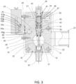
FIG. 3 is a vertical section of one of the liquid dispensing modules of the illustrated liquid dispensing system; -
FIG. 4 is an enlarged vertical section of the central liquid control piston assembly of the liquid dispensing modules shown inFIG. 3 ; -
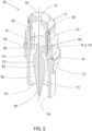
FIG. 5 is an enlarged perspective, in vertical section, of the spray nozzle assembly of one of the liquid dispensing modules of the illustrated system; -
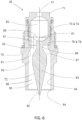
FIG. 6 is a vertical section of the spray nozzle assembly shown inFIG. 5 ; -
FIG. 7 is an exploded perspective of the spray nozzle assembly shown inFIGS. 5 and6 ; and -
FIG. 8 is a diagrammatic depiction of a solenoid control valve associated with each respective liquid dispensing module. - Referring now more particularly to
FIGS. 1-3 of the drawings, there is shown an illustrativeliquid dispensing system 10 in accordance with the invention. The illustratedliquid dispensing system 10 is in the form of amodular valve manifold 11 comprising a plurality of individualliquid dispensing modules 12 supported and retained in sealed side by side stacked relation betweenend blocks 13 and 14 at opposite ends secured together bytie rods 15 andnuts 16. Eachmodule 12 includes a modulenozzle support body 20 formed with aliquid supply port 21 disposed in aligned relation withliquid supply ports 21 of theadjacent modules 12 for defining a commonliquid supply passage 22 communicating between aliquid inlet port 23 in theupstream end block 13 and aliquid outlet port 24 in the downstream end block 14. Hence, liquid directed to theinlet 23 communicates through each of the stackedmodules 12. - Each illustrated
module 12 has arespective spray nozzle 30 mounted in depending relation to an underside of the modulenozzle support body 20 having an upstreamliquid inlet 31 in an upper side communicating with theliquid supply passage 22. For controlling liquid from the commonliquid supply passage 22 to thespray nozzle inlet 31 of the module 12 apiston 32 is supported in eachmodule body 20 above thespray nozzle inlet 31 for reciprocating movement between a raised inlet open position and a lowered inlet closed position. - Each
piston 32 in this case is supported for selective relative movement in acarrier 33 mounted in sealed relation within avertical opening 34 of therespective module body 20 with a downstream end of thepiston 32 extending through theliquid supply passage 22 for engagement with thespray nozzle inlet 31. For biasing thepiston 32 in a lowered position closing thespray nozzle inlet 31, areturn spring 35 is disposed within aspring chamber 36 of themodule body 20 in interposed relation between ahead 32a of thepiston 32 and aretention sleeve 37 secured within an upper end of the body opening 34 and retained by aretention cap 38 threadedly engaged within an upper end of the body opening 34. The retention sleeve 37 in this case extends downwardly about thereturn spring 35 and thepiston head 32a, as best depicted inFIGS. 3 and4 . Thespring retention sleeve 37 and opening 34 of themodule body 20 in this case define an annular air flow passage 40 (FIG. 3 ) about theretention sleeve 37 which communicates to and through thespring chamber 36 by circumferentially offsetholes 41 in thespring retention sleeve 37. A sealedpiston chamber 42 is defined between opposing axel ends of thepiston head 32a and the carrier 42 (FIG. 4 ). - Pursuant to an important feature of this embodiment, each module body has a pressurized air passage system controlled by a respective valve such that pressurized air that moves the piston to an open position also augments rapid movement of the piston to closure. In the illustrated embodiment, operation of the
piston 32 of eachmodule 12 between open and closed positions is controlled by arespective solenoid valve 43, as best depicted inFIGS. 3 and8 . Eachmodule solenoid valve 43 is attached to itsrespective module body 20 with asolenoid mounting block 44 mounted in sealed relation to itsrespective module body 20 byscrews 45. Themodule bodies 20 each have anair supply port 50 aligned with theair supply port 50 of each adjacent module body to define a common air inlet passage communicating with a systemair inlet port 51 in the end block 14. Themodule bodies 20 further each have anair outlet port 52 aligned to define a common outlet air passage communicating with a system exhaust outlet port 53 in the end block 14. Theair supply port 50 of themodule body 20 communicates throughinlet air passages module body 20 andsolenoid mounting block 44 to an air inlet port 55a of thesolenoid valve 43. Theair outlet port 52 of themodule body 20 communicates throughoutlet passage 60 with thereturn spring chamber 36 viaholes 41 in theretention sleeve 37 and theannular passage 40 about thesleeve 37, andoutlet passages module body 20 andsolenoid mounting block 44 with anexhaust port 55b of thesolenoid valve 43. Thepiston chamber 42 communicates viawork passages module body 20 andsolenoid mounting block 44 with awork port 55c of thesolenoid control valve 43. - When the
solenoid valve 43 in this case is in its natural or non-energized state, inlet pressure at solenoid valve port air inlet 55a is blocked by amechanism 43a, in this case in the form of a stem, of the solenoid valve 43 (FIG. 8 ) preventing pressurized air at theair supply port 50 of themodule body 20 from communicating with thepiston chamber 42 viapassages solenoid mounting block 44 andmodule body 20. Additional passage routing when thesolenoid valve 43 is in its natural or non-energized state connectsports solenoid valve 43, allowing communication of air betweenpiston chamber 42 andoutlet port 52 in themodule body 20 viapassages module body 20 andsolenoid mounting block 44,outlet passages solenoid mounting block 44 andmodule body 20, theannular passage 40 about through thespring 35 viaholes 41, andoutlet passage 60. - When the
solenoid valve 43 is energized, the solenoid shifts actuatingmechanism 43a to closeexhaust port 55b removing the connection ofport 55c to atmosphere and connectingsolenoid valve ports 55a, 55c. Pressurized air at theair supply port 50 ofmodule body 20 then communicates withpressure chamber 42 viapassages module body 20 andsolenoid mounting block 44,solenoid valve ports 55a, 55c andpassages piston 32 to stroke upwardly, opening the nozzle inlet 31 and compressing thereturn spring 35. The upward stroke of thepiston head 32a imparts a positive air displacement within thespring chamber 36 resulting in a slight pressure increase. The pressure increase in thespring cavity 36 drains throughholes 41 in thespring retention sleeve 37,annular passage 40,outlet passage 60, andair outlet port 52 to atmosphere pressure (FIGS. 3 and4 ). Thenozzle inlet 31 remains open, allowing liquid flow, from the commonliquid supply passage 22 through thespray nozzle 30 to atmosphere while the solenoid is energized. - When un-energized, the
solenoid valve 43 shifts back to the natural state. Inlet air pressure at solenoid port 55a is again blocked preventing pressurized air from entering the device. Rapid decompression of the pressurized air inpiston chamber 42 causes a migration of elevated pressure withinpassages module body 20 andsolenoid mounting block 44,ports solenoid valve 43,outlet passage solenoid mounting block 44 andmodule body 20,spring chamber 36,outlet passage 60, andoutlet port 52 as the system pressure inpiston chamber 42 is released and equalizes with the atmosphere. Migrating pressure in theannular passage 40 communicates throughholes 41 inspring retention sleeve 37 causing elevated pressure withinspring chamber 36 and acting on the surface area ofpiston head 32a within thespring chamber 36 resulting in a momentary downward force supplementing the constant downward force fromreturn spring 35 opposing the decompressing pressure in thepiston chamber 42, returningpiston 32 to its natural state,closing passage 31 and stopping liquid flow throughspray nozzle 30, from commonliquid supply passage 22. An appreciable decrease in time required to return thepiston 32 to its natural state is attributed to the momentary increase in pressure within thespring chamber 36. All passages and cavities downstream ofsolenoid valve 43 includingspring chamber 36 intrinsically return to atmospheric pressure through anoutlet port 52 effectively removing the supplemental force the transient pressure applied topiston head 32a. - Further operation of the
liquid dispensing module 12 by again energizingsolenoid 43 is unaffected by the previous cycles increased pressure in thespring chamber 36 as the increased pressure is transient and quickly returns to atmosphere pressure allowing the increased pressure to have the desired effect on piston's 32 opening stroke without effecting the piston's 32 closing stroke. As it will become apparent, thesolenoid valve 43 can be cycled at predetermined rates for the particular dispensing operation with the piston's 32 variable open time providing a varying pixel volume. - In accordance with a further aspect of the present embodiment, each
spray nozzle module 12 is operative for dispensing controlled small round pixel sized droplets of highly viscous liquid as an incident to cycling of thepiston 32 even when the liquid has an appreciable solids content. Eachspray nozzle 30 with particular reference toFIGS. 5 ,6 , and7 , in this case comprises anozzle body 70, anozzle seat 71 and aninternal nozzle core 72. Thenozzle seat 71 in this instance has an externally threaded cylindricaldownstream end 73 that is threadedly engaged within an upstreamcylindrical end 74 of thenozzle body 70 to secure thenozzle core 92 within thenozzle body 70. Anupstream end 75 of thenozzle seat 71 defines the predetermined sizeliquid inlet 31, which is at the upstream end of the assembly. Thenozzle core 72 in this instance has an upstreamcylindrical mounting flange 78 positioned on anannular ledge 79 within thenozzle body 70 and retained in place by thenozzle seat 71, although it will be appreciated that other methods may be used to secure thenozzle core 72 within thenozzle body 70. - The cylindrical mounting
flange 78 of thecore 72 has a concavely configured (relative to the direction of fluid flow)downstream end wall 80 formed with a plurality of circumferentially spaced axially orientedliquid orifices 81. These liquid orifices that communicate between anexpansion cavity 82 of thenozzle seat 71 and an annularly configured liquid discharge passage defined between thenozzle core 72 and thenozzle body 70 for directing liquid in a controlled fashion for optimum dispensing in small droplet form as will become apparent. It will be understood that while the illustratednozzle 30 comprises a multi-part assembly, alternatively, it could have a one-piece construction or fewer or greater assembled parts. - In carrying out this aspect of the present embodiment, the
nozzle core 72 has a teardrop shapedpintle 83 which together with the internal circumferential surface of the surroundingnozzle body 70 defines an expandingdischarge passage 85 that reduces exit velocity of the dispensed liquid for maintaining a desired flow rate and consistent droplet size of the highly viscous discharging liquid. To that end, the illustrated pintle 83 (seeFIGS. 5 ,6 , and7 ) has a relatively small diameterupstream end section 86 extending centrally from the mountingflange 78, a radially outwardly extendingcurved section 87 adjacent to the upstream end, and an inwardly tapered, relatively long conicalterminal end section 90. As noted, thenozzle body 70 has a generally hollow cylindrical configuration with the internal circumferential surface of thenozzle body 70 defining the outer wall of theannular discharge passage 85 about thecore section 72. The inner wall of thedischarge passage 85 is defined by the outer surface of thepintle 83. In this case, the internal circumferential surface of thenozzle body 70 includes a radially outwardly directedsection 91 that extends in surrounding relation to the outwardlycurved section 87 of thenozzle core 72 and auniform diameter section 84 that then extends downstream substantially the remaining length of thepintle 83. The design is unique in that flow through the annular discharge passage effects inward expansion of viscous liquid during travel through the nozzle body. The geometry of the pintle defines the inner diametric wall of the annular flow path while providing a structure against which a vacuum due to the flow expansion can be formed. The deceleration of the liquid within the expanding annular discharge passage is a function of the surface tension and the capillary forces' ability to draw a vacuum and resist flow. - In operation, with continued reference to
FIG. 3 , when thepiston 32 is in a raised inlet open position, liquid is permitted to pass through thenozzle inlet 31 in a controlled fashion into theexpansion cavity 82 defined within the cylindrical downstream end of thenozzle seat 71. Liquid passing through thenozzle inlet 31 is directed against an impingement surface defined by the concavedownstream end wall 80 of theexpansion cavity 82. This causes liquid to fill theexpansion cavity 82 and then subsequently extrude from the expansion cavity through the series of circumferentially spacedorifices 81 into thedischarge passage 85. Moreover, the size of each of theorifices 81 is at least as large as thenozzle inlet 31 to allow solid particles in the liquid to flow from theexpansion cavity 82 to thefluid discharge passage 85 without clogging. The collective area of the circumferentially spacedorifices 81 is greater than the area of thenozzle inlet 31 such that the velocity of the liquid passing through theorifices 81 is inversely proportional to the ratio of the size of theorifices 81 to the size of thenozzle inlet 31. - More specifically, the
circumferential orifices 81 at the downstream end of theexpansion cavity 82 communicate with aninlet section 92 of thedischarge passage 85 that is defined between the outwardly directedwall section 91 of thenozzle body 70 and thepintle 83 of thenozzle core 72. The cross-sectional area of theannular inlet section 92 may increase as the section extends in the downstream direction such that the velocity of the fluid in this region continues to be reduced as the cross-sectional area of the discharge passage expands. A slight reduction in the cross-sectional area of thedischarge passage 85 in a subsequent stabilizingsection 93 of the discharge passage 85 (again defined by the outer surface of thepintle 83 and the inner circumferential surface of the nozzle body 70) immediately downstream of theinlet section 92 can provide a slight increase in pressure. This increase in pressure stabilizes and balances the flow removing individual jet streams caused by the fluid entering theinlet section 92 of thedischarge passage 85 through the series oforifices 81 and allows uniform flow along the internal wall surface of thenozzle body 70. The cross-sectional area of the stabilizingsection 93 remains constant through this region as the fluid gains stability. - Downstream of the stabilizing
section 93, the liquid enters afinal expansion section 95 defined by the inwardly taperedterminal end section 90 of thenozzle core 72 that extends downstream to anozzle mouth 94 defined at the downstream end of thenozzle body 70. The progressively increasing cross-sectional area of thefinal expansion section 95 is achieved through the reducing conical diameter of thepintle 83 in theterminal end section 90 while the inner circumferential surface of thenozzle body 70 is maintained at a consistent diameter. Thepintle 83 helps stabilize the fluid and enables greater expansion of the liquid than could be achieved with nozzle core having a simple uniform diameter. Sustained contact of the liquid with inner and outer wall surfaces of the discharge passage is a function of the surface tension of the liquid. - The cross-sectional area of the
final expansion section 95 at thenozzle mouth 94 defines the exit velocity of the liquid, which is inversely proportional to the cross-sectional area at thenozzle mouth 94 in relation to the area ofnozzle inlet 31. Theterminal end section 90 of thenozzle core 72 preferably extends slightly beyond thenozzle mouth 94 to assist in breaking the surface tension of the liquid with the inner circumferential surface of thenozzle body 70 without impacting the outer diameter of the discharging liquid stream. Having the inner circumferential surface of thenozzle body 70 at a constant diameter helps establish a consistent diameter of the boundary layer of the liquid when it exits the nozzle, which assists in maintaining the desired droplet diameter independent of the distance of the nozzle from the target. - It has been found that a dramatic reduction in the velocity of the liquid can be achieved through progressively increasing the cross-sectional area of the
discharge passage 85. The inward expansion of thedischarge passage 85 is achieved by progressively reducing the diameter of thepintle 83 while maintaining the inner circumferential surface of thenozzle body 70. This helps produce discharging liquid with a consistent stream diameter. The reduced velocity of the liquid allows it to be dispensed without splattering. This further allows the utilization of largernozzle inlet orifices 31 for enabling the dispensing of liquids with larger solids content. Once the discharge passage of the nozzle is initially filled with viscous fluid, the surface tension of the liquid will keep thenozzle 30 charged with liquid ready to be dispensed upon opening of thenozzle inlet 31. Because the liquid can be substantially incompressible, an exact relationship can be maintained between the liquid volume entering thenozzle 30 through theinlet 31 and the liquid exiting thenozzle mouth 94. Cycling thepiston 32 to open and close theinlet orifice 31 at a rapid rate, such as 50 milliseconds, has been found to produce small, consistent droplets of liquid that are discharged at a reduced exit velocity. This allows the discharging droplets to be deposited on a target, such as a target about 2 inches from the nozzle, without splattering. - From the foregoing, it can be seen that a liquid dispensing system is provided that can be selectively operated for dispensing precisely controlled droplets without undesirable splattering of the dispensed liquid. The system further includes spray nozzles that are less susceptible to clogging from the solids content of the liquid. Yet the liquid dispensing system and the liquid spray nozzles thereof are relatively simple in design and lends itself to economical manufacture and efficient usage. While the spray nozzles have been shown and described in conjunction with an illustrative liquid dispensing system, it will be understood that the spray nozzles could be used in other applications for dispensing controlled relatively small quantities of liquid.
Claims (9)
- A spray nozzle comprising:a nozzle seat (71) having a liquid inlet and an expansion cavity (82) in fluid communication with the liquid inlet (31), the expansion cavity terminating at a downstream end wall (80);a nozzle body (70) having a generally hollow cylindrical configuration defining an internal circumferential surface; andan internal nozzle core (72) arranged within the nozzle body (70), said nozzle core (72) including a teardrop shaped pintle (83) having an upstream end section (86) adjacent to the upstream end wall of the expansion cavity, a radially outward curved section (87) adjacent to the upstream end section (86) and a radially inwardly tapered conical terminal end section (90), an annular discharge passage (85) being defined between an outer surface of the pintle (83) and the internal circumferential surface of the nozzle body (70) that is in fluid communication with the expansion cavity of the nozzle seat; characterized by the annular discharge passage (85) including an expansion section (95) defined by the radially inwardly tapered conical terminal end section (90), wherein the expansion section (95) has a cross-sectional area that progressively increases as the expansion section extends in the downstream direction.
- The spray nozzle of claim 1 wherein the downstream end wall (80) of the expansion cavity (82) of the nozzle seat has a concave configuration relative to a direction of liquid travel.
- The spray nozzle of claim 2 wherein the downstream end wall (80) of the nozzle seat includes a plurality of circumferentially spaced orifices (81) each of which is in fluid communication with the annular discharge passage (85).
- The spray nozzle of claim 3 wherein each of the circumferentially spaced orifices (81) has a cross-sectional area equal to or greater than a cross-sectional area of the liquid inlet (31).
- The spray nozzle of claim 1 wherein the internal circumferential surface of the nozzle body (70) includes a radially outwardly directed section (91) that extends in surrounding relation to the outward curved section (87) of the pintle and a uniform diameter section (84) that extends in surrounding relation to a remaining length of the pintle (83).
- The spray nozzle of claim 5 wherein an inlet section (92) of the annular discharge passage is defined between the radially outwardly direction section (91) of the internal circumferential surface of the nozzle body (70) and the outward curved section (87) of the pintle with the inlet section (92) of the discharge passage having a cross-sectional area that increases as the inlet section extends in the downstream direction.
- The spray nozzle of claim 6 wherein the annular discharge passage (85) includes a stabilizing section (93) downstream of the inlet section (92) and wherein the stabilizing section (93) has a cross-sectional area less than the cross-sectional area at a downstream end of the inlet section (92).
- The spray nozzle of claim 1 wherein a downstream end of the nozzle body defines a nozzle mouth (94) and wherein the terminal end section (90) of the pintle extends beyond the nozzle mouth.
- The spray nozzle of claim 1 wherein the nozzle seat (71) is engaged within an upstream end of the nozzle body (70) and the nozzle core (72) has an upstream mounting flange (78) that is positioned on annular ledge (79) in the nozzle body and retained in place by the nozzle seat (71).
Applications Claiming Priority (2)
| Application Number | Priority Date | Filing Date | Title |
|---|---|---|---|
| US202063076001P | 2020-09-09 | 2020-09-09 | |
| PCT/US2021/049676 WO2022056136A1 (en) | 2020-09-09 | 2021-09-09 | Liquid dispensing spray nozzle assembly |
Publications (3)
| Publication Number | Publication Date |
|---|---|
| EP4210876A1 EP4210876A1 (en) | 2023-07-19 |
| EP4210876B1 true EP4210876B1 (en) | 2024-11-06 |
| EP4210876C0 EP4210876C0 (en) | 2024-11-06 |
Family
ID=78078418
Family Applications (2)
| Application Number | Title | Priority Date | Filing Date |
|---|---|---|---|
| EP21787135.9A Active EP4210876B1 (en) | 2020-09-09 | 2021-09-09 | Liquid dispensing spray nozzle assembly |
| EP21786705.0A Active EP4210875B1 (en) | 2020-09-09 | 2021-09-09 | Liquid dispensing system with pressurized air operated liquid control pistons |
Family Applications After (1)
| Application Number | Title | Priority Date | Filing Date |
|---|---|---|---|
| EP21786705.0A Active EP4210875B1 (en) | 2020-09-09 | 2021-09-09 | Liquid dispensing system with pressurized air operated liquid control pistons |
Country Status (11)
| Country | Link |
|---|---|
| US (3) | US12023693B2 (en) |
| EP (2) | EP4210876B1 (en) |
| JP (2) | JP2023540139A (en) |
| KR (3) | KR20230064621A (en) |
| CN (3) | CN116507422A (en) |
| BR (2) | BR112023004357A2 (en) |
| CA (2) | CA3194207A1 (en) |
| ES (2) | ES2994216T3 (en) |
| MX (3) | MX2023002770A (en) |
| PL (2) | PL4210876T3 (en) |
| WO (2) | WO2022056136A1 (en) |
Families Citing this family (7)
| Publication number | Priority date | Publication date | Assignee | Title |
|---|---|---|---|---|
| US11684947B2 (en) * | 2018-11-09 | 2023-06-27 | Illinois Tool Works Inc. | Modular fluid application device for varying fluid coat weight |
| WO2024173350A1 (en) * | 2023-02-16 | 2024-08-22 | Spraying Systems Co. | Liquid dispensing spray nozzle assembly for rapidly producing small sized droplets of highly viscous liquids |
| CA3194207A1 (en) | 2020-09-09 | 2022-03-17 | Spraying Systems Co. | Liquid dispensing system with pressurized air operated liquid control pistons |
| CN115555142B (en) * | 2022-11-11 | 2024-06-25 | 湖南农业大学 | Air pressure and adaptive combined variable nozzle and control method thereof |
| CN117989380B (en) * | 2024-04-02 | 2024-05-31 | 常州克劳诺斯特种轴承制造有限公司 | A quantitative discharge valve body and quantitative discharge method thereof |
| US20250372871A1 (en) * | 2024-05-29 | 2025-12-04 | Dell Products L.P. | Information handling system dongle with embedded separable antenna |
| CN121042185A (en) * | 2025-11-03 | 2025-12-02 | 温州康润洁具有限公司 | Assembly method of solar shower head and solar shower head |
Family Cites Families (26)
| Publication number | Priority date | Publication date | Assignee | Title |
|---|---|---|---|---|
| US4066188A (en) * | 1976-08-10 | 1978-01-03 | Nordson Corporation | Thermoplastic adhesive dispenser having an internal heat exchanger |
| SU776647A2 (en) | 1979-01-02 | 1980-11-07 | Научно-Исследовательский Институт Научно-Производственного Объединения "Лакокраспокрытие" | Sprayer |
| JPS5732050U (en) * | 1980-07-30 | 1982-02-19 | ||
| US4555766A (en) * | 1981-10-09 | 1985-11-26 | General Signal Corporation | Brake control system for vehicles |
| MX9300856A (en) * | 1992-02-17 | 1994-07-29 | Orbital Eng Pty | INJECTOR NOZZLE FOR AN INTERNAL COMBUSTION ENGINE WITH FUEL INJECTION. |
| US6253957B1 (en) * | 1995-11-16 | 2001-07-03 | Nordson Corporation | Method and apparatus for dispensing small amounts of liquid material |
| US5992529A (en) * | 1996-12-16 | 1999-11-30 | Williams Fire & Hazard Control, Inc. | Mixing passage in a foam fire fighting nozzle |
| DE29622341U1 (en) | 1996-12-23 | 1997-04-03 | Nordson Corp., Westlake, Ohio | Device for applying flowable material to a substrate, in particular for the intermittent application of liquid adhesive |
| US5934520A (en) * | 1997-11-03 | 1999-08-10 | Nordson Corporation | Liquid dispensing device |
| US6296463B1 (en) * | 1998-04-20 | 2001-10-02 | Nordson Corporation | Segmented metering die for hot melt adhesives or other polymer melts |
| US6089413A (en) * | 1998-09-15 | 2000-07-18 | Nordson Corporation | Liquid dispensing and recirculating module |
| US6036106A (en) * | 1999-02-04 | 2000-03-14 | Nordson Corporation | Dispenser having liquid discharge assembly with high wear and thermal conductivity properties |
| US6669057B2 (en) * | 2001-10-31 | 2003-12-30 | Nordson Corporation | High-speed liquid dispensing modules |
| EP2267381B1 (en) * | 2003-07-14 | 2015-12-16 | Nordson Corporation | Apparatus for dispensing discrete amounts of viscous material |
| DE10357088A1 (en) * | 2003-12-06 | 2005-07-07 | Breitwieser, Michael, Dipl.-Ing. | Annular gap nozzle for viscous fluid metering has circular section flow channel with defined flow resistance |
| JP4089915B2 (en) * | 2005-08-09 | 2008-05-28 | 三菱電機株式会社 | Fuel injection valve |
| CN201132141Y (en) * | 2007-11-29 | 2008-10-15 | 陈江 | Spraying type dispensing valve |
| DE102009037828A1 (en) * | 2008-11-11 | 2010-05-20 | Wurz, Dieter, Prof. Dr. | Two-fluid nozzle, bundling nozzle and method for atomizing fluids |
| ES2764998T3 (en) * | 2009-09-21 | 2020-06-05 | Nordson Corp | Pneumatically actuated liquid dispensing valve |
| CN202785722U (en) * | 2012-09-19 | 2013-03-13 | 无锡联营电力设备有限公司 | Swirl nozzle |
| BR112014011873B1 (en) * | 2012-12-25 | 2020-10-13 | Spraying Systems Co., Japan | full cone spray nozzle |
| DE202013011012U1 (en) * | 2013-12-16 | 2015-03-19 | Liquidyn Gmbh | Dosing valve for liquids |
| US20160256889A1 (en) * | 2015-03-06 | 2016-09-08 | Nordson Corporation | Variable output dispensing applicator and associated methods of dispensing |
| CN107824349A (en) * | 2017-11-01 | 2018-03-23 | 中国恩菲工程技术有限公司 | Activated carbon nozzle |
| EP3769855B1 (en) * | 2018-03-20 | 2024-03-13 | Musashi Engineering, Inc. | Liquid material ejecting apparatus |
| CA3194207A1 (en) | 2020-09-09 | 2022-03-17 | Spraying Systems Co. | Liquid dispensing system with pressurized air operated liquid control pistons |
-
2021
- 2021-09-09 CA CA3194207A patent/CA3194207A1/en active Pending
- 2021-09-09 MX MX2023002770A patent/MX2023002770A/en unknown
- 2021-09-09 PL PL21787135.9T patent/PL4210876T3/en unknown
- 2021-09-09 EP EP21787135.9A patent/EP4210876B1/en active Active
- 2021-09-09 KR KR1020237011822A patent/KR20230064621A/en active Pending
- 2021-09-09 EP EP21786705.0A patent/EP4210875B1/en active Active
- 2021-09-09 JP JP2023515608A patent/JP2023540139A/en active Pending
- 2021-09-09 BR BR112023004357A patent/BR112023004357A2/en unknown
- 2021-09-09 WO PCT/US2021/049676 patent/WO2022056136A1/en not_active Ceased
- 2021-09-09 CN CN202180075383.7A patent/CN116507422A/en active Pending
- 2021-09-09 ES ES21786705T patent/ES2994216T3/en active Active
- 2021-09-09 CA CA3192106A patent/CA3192106A1/en active Pending
- 2021-09-09 PL PL21786705.0T patent/PL4210875T3/en unknown
- 2021-09-09 MX MX2023002771A patent/MX2023002771A/en unknown
- 2021-09-09 CN CN202180075363.XA patent/CN116457105A/en active Pending
- 2021-09-09 KR KR1020237010122A patent/KR20230085908A/en active Pending
- 2021-09-09 BR BR112023004311A patent/BR112023004311A2/en unknown
- 2021-09-09 ES ES21787135T patent/ES2992648T3/en active Active
- 2021-09-09 US US17/470,771 patent/US12023693B2/en active Active
- 2021-09-09 JP JP2023515304A patent/JP2023541832A/en active Pending
- 2021-09-09 US US17/470,724 patent/US12403488B2/en active Active
- 2021-09-09 WO PCT/US2021/049674 patent/WO2022056134A1/en not_active Ceased
-
2023
- 2023-02-16 US US18/110,569 patent/US12208401B2/en active Active
-
2024
- 2024-02-13 CN CN202480012770.XA patent/CN120693214A/en active Pending
- 2024-02-13 KR KR1020257026987A patent/KR20250146346A/en active Pending
-
2025
- 2025-08-14 MX MX2025009570A patent/MX2025009570A/en unknown
Also Published As
| Publication number | Publication date |
|---|---|
| CN120693214A (en) | 2025-09-23 |
| WO2022056134A1 (en) | 2022-03-17 |
| US20230191430A1 (en) | 2023-06-22 |
| JP2023541832A (en) | 2023-10-04 |
| CN116457105A (en) | 2023-07-18 |
| EP4210876C0 (en) | 2024-11-06 |
| BR112023004357A2 (en) | 2023-04-04 |
| PL4210875T3 (en) | 2024-12-16 |
| MX2023002770A (en) | 2023-05-26 |
| EP4210876A1 (en) | 2023-07-19 |
| WO2022056136A1 (en) | 2022-03-17 |
| BR112023004311A2 (en) | 2023-04-04 |
| EP4210875C0 (en) | 2024-10-09 |
| PL4210876T3 (en) | 2025-02-10 |
| KR20250146346A (en) | 2025-10-13 |
| KR20230064621A (en) | 2023-05-10 |
| US12208401B2 (en) | 2025-01-28 |
| US20220072568A1 (en) | 2022-03-10 |
| US20220072569A1 (en) | 2022-03-10 |
| MX2023002771A (en) | 2023-05-26 |
| KR20230085908A (en) | 2023-06-14 |
| EP4210875B1 (en) | 2024-10-09 |
| ES2992648T3 (en) | 2024-12-16 |
| CN116507422A (en) | 2023-07-28 |
| CA3192106A1 (en) | 2022-03-17 |
| ES2994216T3 (en) | 2025-01-20 |
| CA3194207A1 (en) | 2022-03-17 |
| MX2025009570A (en) | 2025-09-02 |
| US12403488B2 (en) | 2025-09-02 |
| US12023693B2 (en) | 2024-07-02 |
| JP2023540139A (en) | 2023-09-21 |
| EP4210875A1 (en) | 2023-07-19 |
Similar Documents
| Publication | Publication Date | Title |
|---|---|---|
| EP4210875B1 (en) | Liquid dispensing system with pressurized air operated liquid control pistons | |
| KR100886335B1 (en) | Foam forming unit | |
| EP0729792B1 (en) | Sprayer having variable spray pattern | |
| US4986453A (en) | Atomizing pump | |
| EP0352532A2 (en) | Flat-top valve member for an atomizing pump dispenser | |
| US5522547A (en) | Sprayer having pressure build-up discharge | |
| MX2007010876A (en) | Aerosol dispenser. | |
| US8042750B2 (en) | Release agent spray device for a casting machine | |
| KR20210107070A (en) | Jet dosing valve | |
| US5425477A (en) | Pump sprayer with stationary discharge | |
| EP1036598B1 (en) | High flow pneumatic adhesive applicator valve | |
| HK40098596A (en) | Liquid dispensing spray nozzle assembly | |
| HK40098596B (en) | Liquid dispensing spray nozzle assembly | |
| HK40097262A (en) | Liquid dispensing system with pressurized air operated liquid control pistons | |
| HK40097262B (en) | Liquid dispensing system with pressurized air operated liquid control pistons | |
| EP4665511A1 (en) | Liquid dispensing spray nozzle assembly for rapidly producing small sized droplets of highly viscous liquids | |
| RU2843012C1 (en) | Liquid dispensing system with pneumatically controlled pistons for liquid adjustment | |
| RU2848458C1 (en) | Spray nozzle assembly for dispensing liquid | |
| JP2026514639A (en) | Liquid dispensing spray nozzle assembly for rapidly producing small droplets of highly viscous liquids. | |
| US6102255A (en) | Invertible dispensing means for spray containers | |
| JP4036249B2 (en) | solenoid valve | |
| US11311895B2 (en) | Fluid dispenser having a discharge head | |
| HK1011314B (en) | Sprayer having variable spray pattern | |
| HK1000570A (en) | Pump sprayer with stationary discharge |
Legal Events
| Date | Code | Title | Description |
|---|---|---|---|
| STAA | Information on the status of an ep patent application or granted ep patent |
Free format text: STATUS: UNKNOWN |
|
| STAA | Information on the status of an ep patent application or granted ep patent |
Free format text: STATUS: THE INTERNATIONAL PUBLICATION HAS BEEN MADE |
|
| PUAI | Public reference made under article 153(3) epc to a published international application that has entered the european phase |
Free format text: ORIGINAL CODE: 0009012 |
|
| STAA | Information on the status of an ep patent application or granted ep patent |
Free format text: STATUS: REQUEST FOR EXAMINATION WAS MADE |
|
| 17P | Request for examination filed |
Effective date: 20230307 |
|
| AK | Designated contracting states |
Kind code of ref document: A1 Designated state(s): AL AT BE BG CH CY CZ DE DK EE ES FI FR GB GR HR HU IE IS IT LI LT LU LV MC MK MT NL NO PL PT RO RS SE SI SK SM TR |
|
| DAV | Request for validation of the european patent (deleted) | ||
| DAX | Request for extension of the european patent (deleted) | ||
| RIN1 | Information on inventor provided before grant (corrected) |
Inventor name: COPLIN, THOMAS |
|
| REG | Reference to a national code |
Ref country code: HK Ref legal event code: DE Ref document number: 40098596 Country of ref document: HK |
|
| GRAP | Despatch of communication of intention to grant a patent |
Free format text: ORIGINAL CODE: EPIDOSNIGR1 |
|
| STAA | Information on the status of an ep patent application or granted ep patent |
Free format text: STATUS: GRANT OF PATENT IS INTENDED |
|
| INTG | Intention to grant announced |
Effective date: 20240604 |
|
| GRAS | Grant fee paid |
Free format text: ORIGINAL CODE: EPIDOSNIGR3 |
|
| GRAA | (expected) grant |
Free format text: ORIGINAL CODE: 0009210 |
|
| STAA | Information on the status of an ep patent application or granted ep patent |
Free format text: STATUS: THE PATENT HAS BEEN GRANTED |
|
| GRAL | Information related to payment of fee for publishing/printing deleted |
Free format text: ORIGINAL CODE: EPIDOSDIGR3 |
|
| GRAS | Grant fee paid |
Free format text: ORIGINAL CODE: EPIDOSNIGR3 |
|
| AK | Designated contracting states |
Kind code of ref document: B1 Designated state(s): AL AT BE BG CH CY CZ DE DK EE ES FI FR GB GR HR HU IE IS IT LI LT LU LV MC MK MT NL NO PL PT RO RS SE SI SK SM TR |
|
| REG | Reference to a national code |
Ref country code: GB Ref legal event code: FG4D |
|
| REG | Reference to a national code |
Ref country code: CH Ref legal event code: EP |
|
| REG | Reference to a national code |
Ref country code: DE Ref legal event code: R096 Ref document number: 602021021522 Country of ref document: DE |
|
| REG | Reference to a national code |
Ref country code: IE Ref legal event code: FG4D |
|
| U01 | Request for unitary effect filed |
Effective date: 20241106 |
|
| REG | Reference to a national code |
Ref country code: ES Ref legal event code: FG2A Ref document number: 2992648 Country of ref document: ES Kind code of ref document: T3 Effective date: 20241216 |
|
| U07 | Unitary effect registered |
Designated state(s): AT BE BG DE DK EE FI FR IT LT LU LV MT NL PT RO SE SI Effective date: 20241211 |
|
| PG25 | Lapsed in a contracting state [announced via postgrant information from national office to epo] |
Ref country code: HR Free format text: LAPSE BECAUSE OF FAILURE TO SUBMIT A TRANSLATION OF THE DESCRIPTION OR TO PAY THE FEE WITHIN THE PRESCRIBED TIME-LIMIT Effective date: 20241106 Ref country code: IS Free format text: LAPSE BECAUSE OF FAILURE TO SUBMIT A TRANSLATION OF THE DESCRIPTION OR TO PAY THE FEE WITHIN THE PRESCRIBED TIME-LIMIT Effective date: 20250306 |
|
| PG25 | Lapsed in a contracting state [announced via postgrant information from national office to epo] |
Ref country code: NO Free format text: LAPSE BECAUSE OF FAILURE TO SUBMIT A TRANSLATION OF THE DESCRIPTION OR TO PAY THE FEE WITHIN THE PRESCRIBED TIME-LIMIT Effective date: 20250206 |
|
| PG25 | Lapsed in a contracting state [announced via postgrant information from national office to epo] |
Ref country code: GR Free format text: LAPSE BECAUSE OF FAILURE TO SUBMIT A TRANSLATION OF THE DESCRIPTION OR TO PAY THE FEE WITHIN THE PRESCRIBED TIME-LIMIT Effective date: 20250207 |
|
| PG25 | Lapsed in a contracting state [announced via postgrant information from national office to epo] |
Ref country code: RS Free format text: LAPSE BECAUSE OF FAILURE TO SUBMIT A TRANSLATION OF THE DESCRIPTION OR TO PAY THE FEE WITHIN THE PRESCRIBED TIME-LIMIT Effective date: 20250206 |
|
| PG25 | Lapsed in a contracting state [announced via postgrant information from national office to epo] |
Ref country code: SM Free format text: LAPSE BECAUSE OF FAILURE TO SUBMIT A TRANSLATION OF THE DESCRIPTION OR TO PAY THE FEE WITHIN THE PRESCRIBED TIME-LIMIT Effective date: 20241106 |
|
| PG25 | Lapsed in a contracting state [announced via postgrant information from national office to epo] |
Ref country code: SK Free format text: LAPSE BECAUSE OF FAILURE TO SUBMIT A TRANSLATION OF THE DESCRIPTION OR TO PAY THE FEE WITHIN THE PRESCRIBED TIME-LIMIT Effective date: 20241106 |
|
| PG25 | Lapsed in a contracting state [announced via postgrant information from national office to epo] |
Ref country code: CZ Free format text: LAPSE BECAUSE OF FAILURE TO SUBMIT A TRANSLATION OF THE DESCRIPTION OR TO PAY THE FEE WITHIN THE PRESCRIBED TIME-LIMIT Effective date: 20241106 |
|
| U20 | Renewal fee for the european patent with unitary effect paid |
Year of fee payment: 5 Effective date: 20250807 |
|
| PLBE | No opposition filed within time limit |
Free format text: ORIGINAL CODE: 0009261 |
|
| STAA | Information on the status of an ep patent application or granted ep patent |
Free format text: STATUS: NO OPPOSITION FILED WITHIN TIME LIMIT |
|
| 26N | No opposition filed |
Effective date: 20250807 |
|
| PGFP | Annual fee paid to national office [announced via postgrant information from national office to epo] |
Ref country code: PL Payment date: 20250730 Year of fee payment: 5 |
|
| PGFP | Annual fee paid to national office [announced via postgrant information from national office to epo] |
Ref country code: GB Payment date: 20250717 Year of fee payment: 5 |
|
| PGFP | Annual fee paid to national office [announced via postgrant information from national office to epo] |
Ref country code: ES Payment date: 20251014 Year of fee payment: 5 |
|
| REG | Reference to a national code |
Ref country code: CH Ref legal event code: H13 Free format text: ST27 STATUS EVENT CODE: U-0-0-H10-H13 (AS PROVIDED BY THE NATIONAL OFFICE) Effective date: 20260504 |