EP4210318A2 - Data processing system, method for determining coordinates, and computer readable storage medium - Google Patents
Data processing system, method for determining coordinates, and computer readable storage medium Download PDFInfo
- Publication number
- EP4210318A2 EP4210318A2 EP22207299.3A EP22207299A EP4210318A2 EP 4210318 A2 EP4210318 A2 EP 4210318A2 EP 22207299 A EP22207299 A EP 22207299A EP 4210318 A2 EP4210318 A2 EP 4210318A2
- Authority
- EP
- European Patent Office
- Prior art keywords
- positioning
- data
- positioning device
- processing device
- camera
- Prior art date
- Legal status (The legal status is an assumption and is not a legal conclusion. Google has not performed a legal analysis and makes no representation as to the accuracy of the status listed.)
- Granted
Links
Images




Classifications
-
- G—PHYSICS
- G06—COMPUTING OR CALCULATING; COUNTING
- G06T—IMAGE DATA PROCESSING OR GENERATION, IN GENERAL
- G06T7/00—Image analysis
- G06T7/70—Determining position or orientation of objects or cameras
-
- G—PHYSICS
- G06—COMPUTING OR CALCULATING; COUNTING
- G06T—IMAGE DATA PROCESSING OR GENERATION, IN GENERAL
- G06T19/00—Manipulating three-dimensional [3D] models or images for computer graphics
- G06T19/006—Mixed reality
-
- H—ELECTRICITY
- H04—ELECTRIC COMMUNICATION TECHNIQUE
- H04N—PICTORIAL COMMUNICATION, e.g. TELEVISION
- H04N23/00—Cameras or camera modules comprising electronic image sensors; Control thereof
- H04N23/60—Control of cameras or camera modules
- H04N23/66—Remote control of cameras or camera parts, e.g. by remote control devices
- H04N23/661—Transmitting camera control signals through networks, e.g. control via the Internet
-
- G—PHYSICS
- G06—COMPUTING OR CALCULATING; COUNTING
- G06F—ELECTRIC DIGITAL DATA PROCESSING
- G06F3/00—Input arrangements for transferring data to be processed into a form capable of being handled by the computer; Output arrangements for transferring data from processing unit to output unit, e.g. interface arrangements
- G06F3/01—Input arrangements or combined input and output arrangements for interaction between user and computer
- G06F3/048—Interaction techniques based on graphical user interfaces [GUI]
- G06F3/0481—Interaction techniques based on graphical user interfaces [GUI] based on specific properties of the displayed interaction object or a metaphor-based environment, e.g. interaction with desktop elements like windows or icons, or assisted by a cursor's changing behaviour or appearance
- G06F3/04815—Interaction with a metaphor-based environment or interaction object displayed as three-dimensional [3D], e.g. changing the user viewpoint with respect to the environment or object
-
- G—PHYSICS
- G06—COMPUTING OR CALCULATING; COUNTING
- G06T—IMAGE DATA PROCESSING OR GENERATION, IN GENERAL
- G06T15/00—Three-dimensional [3D] image rendering
- G06T15/10—Geometric effects
- G06T15/20—Perspective computation
- G06T15/205—Image-based rendering
-
- G—PHYSICS
- G06—COMPUTING OR CALCULATING; COUNTING
- G06T—IMAGE DATA PROCESSING OR GENERATION, IN GENERAL
- G06T7/00—Image analysis
- G06T7/70—Determining position or orientation of objects or cameras
- G06T7/73—Determining position or orientation of objects or cameras using feature-based methods
- G06T7/75—Determining position or orientation of objects or cameras using feature-based methods involving models
-
- H—ELECTRICITY
- H04—ELECTRIC COMMUNICATION TECHNIQUE
- H04N—PICTORIAL COMMUNICATION, e.g. TELEVISION
- H04N23/00—Cameras or camera modules comprising electronic image sensors; Control thereof
- H04N23/60—Control of cameras or camera modules
- H04N23/695—Control of camera direction for changing a field of view, e.g. pan, tilt or based on tracking of objects
-
- H—ELECTRICITY
- H04—ELECTRIC COMMUNICATION TECHNIQUE
- H04N—PICTORIAL COMMUNICATION, e.g. TELEVISION
- H04N5/00—Details of television systems
- H04N5/222—Studio circuitry; Studio devices; Studio equipment
- H04N5/2224—Studio circuitry; Studio devices; Studio equipment related to virtual studio applications
- H04N5/2226—Determination of depth image, e.g. for foreground/background separation
-
- H—ELECTRICITY
- H04—ELECTRIC COMMUNICATION TECHNIQUE
- H04N—PICTORIAL COMMUNICATION, e.g. TELEVISION
- H04N5/00—Details of television systems
- H04N5/222—Studio circuitry; Studio devices; Studio equipment
- H04N5/262—Studio circuits, e.g. for mixing, switching-over, change of character of image, other special effects ; Cameras specially adapted for the electronic generation of special effects
- H04N5/2628—Alteration of picture size, shape, position or orientation, e.g. zooming, rotation, rolling, perspective, translation
-
- H—ELECTRICITY
- H04—ELECTRIC COMMUNICATION TECHNIQUE
- H04N—PICTORIAL COMMUNICATION, e.g. TELEVISION
- H04N5/00—Details of television systems
- H04N5/222—Studio circuitry; Studio devices; Studio equipment
- H04N5/262—Studio circuits, e.g. for mixing, switching-over, change of character of image, other special effects ; Cameras specially adapted for the electronic generation of special effects
- H04N5/272—Means for inserting a foreground image in a background image, i.e. inlay, outlay
-
- G—PHYSICS
- G06—COMPUTING OR CALCULATING; COUNTING
- G06T—IMAGE DATA PROCESSING OR GENERATION, IN GENERAL
- G06T2207/00—Indexing scheme for image analysis or image enhancement
- G06T2207/30—Subject of image; Context of image processing
- G06T2207/30244—Camera pose
Definitions
- the present disclosure relates to a data processing system, a method for determining coordinates, and a computer readable storage medium.
- the disclosure is directed to a data processing system, a method for determining coordinates, and a computer readable storage medium, which may be used to solve the above technical problems.
- the embodiments of the disclosure provide a data processing system, including a data processing device.
- the data processing device performs: receiving a plurality of positioning data, wherein the plurality of positioning data correspond to device positions of a plurality of positioning devices in a real world, and the positioning devices comprise a first positioning device and a second positioning device; in response to determining that the first positioning device is selected as a reference point of a coordinate system of a virtual world, determining a coordinate of the second positioning device in the coordinate system of the virtual world based on a relative position between the device positions of the first positioning device and the second positioning device.
- the embodiments of the disclosure provide a method for determining coordinates, adapted to a data processing device.
- the method includes: receiving a plurality of positioning data, wherein the plurality of positioning data correspond to device positions of a plurality of positioning devices in a real world, and the positioning devices comprise a first positioning device and a second positioning device; in response to determining that the first positioning device is selected as a reference point of a coordinate system of a virtual world, determining a coordinate of the second positioning device in the coordinate system of the virtual world based on a relative position between the device positions of the first positioning device and the second positioning device.
- the embodiments of the disclosure provide a computer readable storage medium, the computer readable storage medium recording an executable computer program, the executable computer program being loaded by a data processing device to perform steps of: receiving a plurality of positioning data, wherein the plurality of positioning data correspond to device positions of a plurality of positioning devices in a real world, and the positioning devices comprise a first positioning device and a second positioning device; in response to determining that the first positioning device is selected as a reference point of a coordinate system of a virtual world, determining a coordinate of the second positioning device in the coordinate system of the virtual world based on a relative position between the device positions of the first positioning device and the second positioning device.
- the data processing system 10 may include a signal processing device 11, a positioning device 12, a lens encoder 13, a camera device 14, a data processing device 15, a terminal device 16, and a clock source 17.
- the camera device 14 can be used for shooting contents of virtual production.
- the camera device 14 can be disposed in a studio, wherein the studio can be disposed with, for example, a green screen and/or other equipment for shooting (e.g., light sources).
- the studio can be disposed with, for example, a green screen and/or other equipment for shooting (e.g., light sources).
- actors/actresses can stand in front of the green screen, and the camera device 14 can be used to shoot images of the actors/actresses in front of the green screen.
- the image regions corresponding to the actors/actresses can be extracted and combined with virtual backgrounds as the visual contents of virtual production, but the disclosure is not limited thereto.
- the positioning device 12 can be (fixedly) mounted on the camera device 14 via, for examples, screws or other adapting structures. In one embodiment, the positioning device 12 can be used to detect the positioning data P1 of the positioning device 12. Since the positioning device 12 is (fixedly) mounted on the camera device 14, the positioning device 12 can be moved in response to the movement of the camera device 14. In this case, the positioning data P1 of the positioning device 12 can be regarded as the positioning data P1 of the camera device 14.
- the positioning data P1 of the camera device 14 may include raw measurement data of the translation components and/or rotation components (e.g., the 6 degree of freedom) of the camera device 14, but the disclosure is not limited thereto.
- the positioning device 12 can be a tracker attached to the camera device 14 and may detect the positioning data P1 of the positioning device 12 and/or the camera device 14 via, for example, outside-in tracking mechanism or inside-out mechanism. In outside-in tracking case, the environment can be disposed with several base stations emitting beacons for the tracker to accordingly detect the positioning data P1 of the positioning device 12 and/or the camera device 14. In other embodiments, the positioning device 12 can use any existing positioning mechanism to determine the positioning data P1 of the positioning device 12 and/or the camera device 14.
- the lens encoder 13 can be disposed on the camera device 14 and connected to (the lens of) the camera device 14 for measuring/reading/detecting the lens parameter L1 of the lens of the camera device 14.
- the lens parameter L1 obtained by the lens encoder 13 can include at least one counting value corresponding to at least one of an iris, a focus, a focal length of the lens of the camera device 14.
- the counting value can be mapped by, for example, the terminal device 16 to the actual setting values of the iris, the focus, and/or the focal length of the lens of the camera device 14, but the disclosure is not limited thereto.
- the signal processing device 11 may include a first data transmission port 111, a second data transmission port 112, a first processor 113, and a network interface 114.
- the first data transmission port 111 is coupled to the positioning device 12 and receiving the positioning data P1 from the positioning device 12.
- the second data transmission port 112 is coupled to the lens encoder 13 and receives the lens parameter L1 of the camera device 14 from the lens encoder 13.
- the signal processing device 11 can include more data transmission ports for connecting with other positioning devices and/or lens encoders.
- the signal processing device 11 can include two more data transmission ports for connecting two additional lens encoders and receiving the corresponding lens parameter measured by the two additional lens encoders, but the disclosure is not limited thereto.
- the first data transmission port 111, the second data transmission port 112 (and other data transmission ports) can be plug and play ports/interfaces, such as universal serial bus (USB) ports/interfaces, but the disclosure is not limited thereto.
- USB universal serial bus
- the first processor 113 is coupled to the first data transmission port 111 and the second data transmission port 112.
- the first processor 113 may be, for example, a general purpose processor, a special purpose processor, a conventional processor, a digital signal processor (DSP), a plurality of microprocessors, one or more microprocessors in association with a DSP core, a controller, a microcontroller, Application Specific Integrated Circuits (ASICs), Field Programmable Gate Array (FPGAs) circuits, any other type of integrated circuit (IC), a state machine, and the like.
- DSP digital signal processor
- ASICs Application Specific Integrated Circuits
- FPGAs Field Programmable Gate Array
- the first processor 113 encapsulates the positioning data P1 and the lens parameter L1 in at least one data packet.
- the at least one data packet may include a first data packet PA1 containing the lens parameter L1 and a second data packet PA2 containing the positioning data P1, but the disclosure is not limited thereto.
- the network interface 114 is coupled to the first processor 113 and send the at least one data packet to the data processing device 15 for further processing.
- the network interface 114 (and other network interfaces considered in the disclosure) can be, for example, Ethernet interfaces, but the disclosure is not limited thereto.
- the first data packet PA1 can be a User Datagram Protocol (UDP) packet, and the first processor 113 can control the network interface 114 to send the first data packet PA1 via a UDP protocol.
- the second data packet PA2 can be a Transmission Control Protocol / Internet Protocol (TCP/IP) packet, and the first processor 113 can control the network interface 114 to send the second data packet PA2 via a Universal Serial Bus / IP (USB/IP) protocol, but the disclosure is not limited thereto.
- TCP Transmission Control Protocol / Internet Protocol
- USB/IP Universal Serial Bus / IP
- the first data packet PA1 and the second data packet PA2 can be implemented as the packets corresponding to the desired protocol of the designer.
- the data processing device 15 includes a first network interface 151, a second network interface 152, and a second processor 153.
- the second processor 153 is coupled to the first network interface 151 and the second network interface 152, and the possible implementations of the second processor 153 may be referred to the descriptions of the first processor 113, but the disclosure is not limited thereto.
- the first network interface 151 is coupled to the network interface 114 of the signal processing device 11 and receives the at least one data packet (e.g., the first data packet PA1 and the second data packet PA2) from the signal processing device 11.
- the second processor 153 may retrieve the positioning data P1 and the lens parameter L1 from the at least one data packet.
- the second processor 153 may retrieve the lens parameter L1 from the first data packet PA1 and retrieve the positioning data P1 from the second data packet PA2, but the disclosure is not limited thereto.
- the second processor 153 determines a camera pose PO of the camera device 14 based on the positioning data P1.
- the positioning data P1 includes the raw measurement data of the translation components and/or rotation components of the camera device 14
- the second processor 153 may analyse/process the positioning data P1 and accordingly determine the actual translation components and/or rotation components of the camera device 14 as the camera pose PO.
- the signal processing device 11 forwards the raw measurement data (e.g., the positioning data P1 detected by the positioning device 12) of the camera pose PO to the data processing device 15, and the data processing device 15 accordingly determine the camera pose PO by analysing the raw measurement data, but the disclosure is not limited thereto.
- the second processor 153 receives a reference clock signal CS from the clock source 17 coupled to the camera device 14, the data processing device 15, and the terminal device 16.
- the reference clock signal CS can be a reference signal for the camera device 14, the data processing device 15, and the terminal device 16 to perform synchronization.
- the reference clock signal CS may be a pulse train including a plurality of clock pulses, wherein the clock pulses may be provided under a specific frequency. In this case, the duration between adjacent clock pulses can be a reciprocal of the specific frequency.
- the second processor 153 may determine a timestamp TS corresponding to the camera pose PO. For example, the second processor 153 can determine camera pose PO and the timestamp TS in response to one of the clock pulses, wherein the timestamp TS corresponds to a timing point of the one of the clock pulses. In one embodiment, the second processor 153 can use the timing point of the one of the clock pulses as the timestamp TS corresponding to the camera pose PO. That is, the second processor 153 follows the timing of the reference clock signal CS to determine the camera pose PO and the corresponding timestamp TS.
- the second processor 153 encapsulate the camera pose PO, the timestamp TS, and the lens parameter L1 in a data signal S1 and sends the data signal S1 via the second network interface 152.
- the terminal device 16 coupled to the data processing device 15 can be any smart devices and/or computer devices used for rendering visual contents of the virtual production.
- the terminal device 16 can be the computer used by the content creator for editing the visual content of the virtual production, but the disclosure is not limited thereto.
- the terminal device 16 may receive the data signal S1 from the data processing device 15. Accordingly, the terminal device 16 could know the lens parameter L1 and the status of the camera pose PO at the timestamp TS from the data signal S1.
- each image captured by camera device 14 can be labelled, by the camera device 14, with corresponding timestamp based on the reference clock signal CS, and the captured images with the corresponding timestamp would be provided to the terminal device 16.
- the terminal device 16 can know the camera poses of the camera device 14 when shooting the images based on the timestamp of each image and each camera pose.
- the terminal device 16 when the terminal device 16 determines that a specific image among the images captured by the camera device 14 has a timestamp same as the timestamp TS, the terminal device 16 can determine the camera pose PO is the camera pose of the camera device 14 when shooting the specific image.
- the terminal device 16 can run/render a virtual scene (e.g., a VR scene).
- a virtual scene e.g., a VR scene
- the terminal device 16 can crop/segment the image regions corresponding to the real objects from the specific image and combine the cropped image regions with the virtual scene to produce a virtual production video.
- the virtual scene includes a virtual camera corresponding to the camera device 14, and the pose of the virtual camera in the virtual scene needs to be referred to the camera pose PO (e.g., rotation and/or translation) of the camera device 14 when shooting the specific image. Since the solution provided by the embodiments of the disclosure can obtain accurate camera pose PO of the camera device 14, the cropped image region can be accurately combined with the virtual scene, which improves the quality of the virtual production.
- the signal processing device 11 can further receive a lens controlling signal LC and accordingly control the lens encoder 13 to adjust a lens setting of the camera device 14.
- the lens setting of the camera device 14 may include, for example, the iris, focus, and/or focal length of the lens of the camera device 14, and the user can determine the lens setting via, for example, operating a control interface (e.g. software/hardware) of the terminal device 16.
- the terminal device 16 can control the data processing device 15 to send the lens controlling signal LC to the signal processing device 11 according to the setting of the user.
- the signal processing device 11 can control the lens encoder 13 to adjust the lens setting of the camera device 14 to be corresponding to the requirement of the user, but the disclosure is not limited thereto.
- FIG. 2 shows a flow chart of the data processing method according to an embodiment of the disclosure.
- the method of this embodiment may be executed by the signal processing device 11 in FIG. 1 , and the details of each step in FIG. 2 will be described below with the components shown in FIG. 1 .
- step S210 the signal processing device 11 receives the positioning data P1 from the positioning device 12.
- step S220 the signal processing device 11 receives the lens parameter L1 of the camera device 14 from the lens encoder 13.
- step S230 the signal processing device 11 encapsulates the positioning data P1 and the lens parameter L1 in the at least one data packet (e.g., the first data packet PA1 and the second data packet PA2).
- step S240 the signal processing device 11 sends the at least one data packet. Details of the steps in FIG. 2 can be referred to the descriptions in the above, which would not be repeated herein.
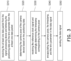
- FIG. 3 shows a flow chart of the data processing method according to an embodiment of the disclosure.
- the method of this embodiment may be executed by the data processing device 15 in FIG. 1 , and the details of each step in FIG. 3 will be described below with the components shown in FIG. 1 .
- step S310 the data processing device 15 receives the at least one data packet from the signal processing device 11 and retrieves the positioning data P1 and the lens parameter L1 from the at least one data packet.
- step S320 the data processing device 15 determines the camera pose PO of the camera device 14 based on the positioning data P1.
- step S330 the data processing device 15 receives the reference clock signal CS and accordingly determine the timestamp TS corresponding to the camera pose PO.
- step S340 the data processing device 15 encapsulates the camera pose PO, the timestamp TS, and the lens parameter L1 in the data signal S1.
- step S350 the data processing device 15 sends the data signal S1. Details of the steps in FIG. 3 can be referred to the descriptions in the above, which would not be repeated herein.
- the embodiments of the disclosure provide an easy, effective solution to accurately track the camera pose of the camera device when shooting contents.
- the user e.g., content creators
- the signal processing device 11 and the data processing device 15 can cooperate to facilitate the terminal device 16 to synchronize the captured images and the camera poses of the camera device 14. Accordingly, the efficiency of creating virtual production can be improved.
- embodiments of the disclosure further provide a method for determining coordinates, which can be carried out by the data processing system of the disclosure, and the details thereof would be introduced in the following.
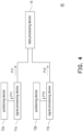
- the data processing system 40 may include signal processing devices 11a, 11b, positioning devices 12a, 12b, and the data processing device 15.
- each of the signal processing devices 11a and 11b can be the same kind of device as the signal processing device 11 in FIG. 1 .
- Each of the positioning devices 12a and 12b can be the same kind of device as the positioning device 12 in FIG. 1
- the data processing device 15 in FIG. 4 can be the same device as the data processing device 15 in FIG. 1 .
- the data processing system 40 can further include other devices in FIG. 1 , such as the lens encoder 13, the terminal device 16, the clock source 17, but the disclosure is not limited thereto.
- the signal processing device 11a and the positioning device 12a can be mounted on the corresponding camera device (not shown) or other to be tracked object/locations.
- the signal processing device 11b and the positioning device 12b can be mounted on the corresponding camera device (not shown) or other to be tracked object/locations.
- the data processing system 40 may include more combinations of the signal processing device and the positioning device, but the disclosure is not limited thereto.
- the data processing device 15 can be disposed with corresponding amount of first network interfaces 151. For example, if the data processing device 15 needs to be able to be connected with up to N (N is a positive integer) signal processing devices, the data processing device 15 can be designed with N first network interfaces 151, but the disclosure is not limited thereto.
- the data processing device 15 may determine the camera poses of the camera devices corresponding to the positioning device 12a, 12b based on the positioning data from the positioning devices 12a, 12b.
- the data processing device 15 can send the determined camera poses of the camera devices to the terminal device 16 for the terminal device 16 to produce the corresponding virtual production (e.g., combining cropped image regions corresponding to real objects with the rendered virtual scene), but the disclosure is not limited thereto.
- FIG. 5 shows a flow chart of the method for determining coordinates according to an embodiment of the disclosure.
- the method of this embodiment may be executed by the data processing device 15 in FIG. 4 , and the details of each step in FIG. 5 will be described below with the components shown in FIG. 4 .
- step S510 the data processing device 15 receives a plurality of positioning data, wherein the plurality of positioning data correspond to device positions of a plurality of positioning devices in a real world, and the positioning devices comprise a first positioning device and a second positioning device.
- the positioning device 12a and 12b would be respectively assumed to be the first positioning device and the second positioning device, but the disclosure is not limited thereto.
- the plurality of positioning data received by data processing device 15 may include a first positioning data P11 corresponding to the positioning device 12a and a second positioning data P12 corresponding to the positioning device 12b.
- the data processing device 15 may receive the first positioning data P11 from the signal processing device 11a connected to the positioning device 12a and receive the second positioning data P12 from the signal processing device 11b connected to the positioning device 12b.
- the signal processing device 11a may receive the positioning data P11 from the positioning device 12a and send the positioning data P11 to the data processing device 15, and the signal processing device 11b may receive the positioning data P12 from the positioning device 12b and send the positioning data P12 to the data processing device 15.
- the data processing device 15 can receive the positioning data P11 and P12 directly from each of the positioning data 12a and 12b, but the disclosure is not limited thereto.
- the positioning data P11 may correspond to a first camera pose of a first camera device on which the signal processing device 11a and the positioning device 12a are mounted
- the positioning data P12 may correspond to a second camera pose of a second camera device on which the signal processing device 11b and the positioning device 12b are mounted, but the disclosure is not limited thereto.
- the positioning devices 12a and 12b may obtain the positioning data P11 and P12 via the outside-in tracking mechanism or inside-out tracking mechanism (e.g. SLAM).
- the positioning data P11 and P12 can be understood as characterizing the positions of the positioning devices 12a and 12b relative to, for example, the base stations, but the disclosure is not limited thereto.
- the data processing device 15 can determine the device positions of the positioning devices 12a and 12b in the real world.
- the positioning data P11 includes the raw measurement data of the translation components and/or rotation components of the positioning device 12a
- the data processing device 15 may analyse/process the positioning data P11 and accordingly determine the actual translation components and/or rotation components of the positioning device 12a, which can be used to determine the device position of the positioning device 12a in the real world.
- the data processing device 15 may analyse/process the positioning data P12 and accordingly determine the actual translation components and/or rotation components of the positioning device 12b, which can be used to determine the device position of the positioning device 12b in the real world.
- step S520 in response to determining that the first positioning device (e.g., the positioning device 12a) is selected as a reference point of a coordinate system of a virtual world, the data processing device 15 determines a coordinate of the second positioning device (e.g., the positioning device 12b) in the coordinate system of the virtual world based on a relative position between the device positions of the first positioning device and the second positioning device.
- the first positioning device e.g., the positioning device 12a
- the data processing device 15 determines a coordinate of the second positioning device (e.g., the positioning device 12b) in the coordinate system of the virtual world based on a relative position between the device positions of the first positioning device and the second positioning device.
- the reference point of the coordinate system of the virtual world would be assumed to be the origin of the coordinate system. In other embodiments, the reference point can be any other desired point in the coordinate system.
- a default reference point is the position of one of the base stations (i.e., the position of the base station regarded as the reference point may be (0, 0, 0)), and the device positions of the positioning device 12a and 12b are respectively (x1, y1, z1) and (x2, y2, z2) in the real world.
- the coordinate of the positioning device 12a in the coordinate system of the virtual world can be, for example, (0,0,0).
- the data processing device 15 may determine the coordinate of the positioning device 12b in the coordinate system of the virtual world to be, for example, (x2-x1, y2-y1, z2-z1), but the disclosure is not limited thereto.
- the data processing device 15 can easily use the relative positions between each of the positioning devices 12a, 12b and the base stations in the real world to determine the coordinates of the positioning devices 12a, 12b in the virtual world, which increases the convenience of creating virtual production.
- the data processing device 15 can further provide the coordinates of the positioning devices 12a, 12b to the terminal device 16 in FIG. 1 , such that the terminal device 16 can use these information to create a visual content with better quality, but the disclosure is not limited thereto.
- the coordinates of the positioning devices 12a, 12b in the virtual world can be easily determined even if the base stations are moved.
- the user may change the locations of the base stations in the studio based on particular requirements. In this case, the user can simply determine the positioning device 12a as the reference point, and the coordinates of the positioning devices 12a and 12b in the virtual world can be properly determined even if the base stations have been moved to new locations.
- the devices positions of the positioning devices 12a and 12b may respectively become (xl', yl', zl') and (x2', y2', z2') relative to the base stations.
- the positioning device 12a is selected as the reference point again, the coordinates of the positioning devices 12a and 12b in the virtual world would be respectively determined to be (0, 0, 0) and (x2'-xl', y2'-yl', z2'-zl'), wherein (x2'-xl', y2'-yl', z2'-zl') would be the same as (x2-x1, y2-y1, z2-z1). Accordingly, the efficiency of creating virtual production can be improved.
- the data processing device 15 in response to determining that the second positioning device (e.g., the positioning device 12b) is selected as the reference point of the coordinate system of the virtual world, can further determine a coordinate of the first positioning device (e.g., the positioning device 12a) in the coordinate system of the virtual world based on the relative position between the device positions of the first positioning device and the second positioning device.
- the first positioning device e.g., the positioning device 12a
- the coordinate of the positioning device 12b in the coordinate system of the virtual world can be, for example, (0,0,0).
- the data processing device 15 may determine the coordinate of the positioning device 12b in the coordinate system of the virtual world to be, for example, (x1-x2, y1-y2, z1-z2), but the disclosure is not limited thereto.
- the data processing device 15 can change to use the positioning device 12b as the origin of the coordinate system of the virtual world, and the coordinates of the positioning devices 12a, 12b would be accordingly updated.
- the data processing device 15 can determine a coordinate of each of other positioning devices in the coordinate system of the virtual world based on a relative position between the device positions of the positioning device selected as the reference point and each of the other positioning devices, but the disclosure is not limited thereto.
- FIG. 6 shows a user interface provided by the data processing device 15 according to an embodiment of the disclosure.
- the data processing device 15 may provide a user interface 610, wherein the user interface 610 shows a re-center function 612.
- the re-center function 612 can be used by the user to select a desired one of the positioning devices as the reference point of the coordinate system of the virtual world.
- the data processing device 15 in response to determining that the re-center function 612 is triggered, can provide a plurality of detected positioning devices in the user interface 610. In one embodiment, the data processing device 15 can detect the positioning devices by checking the positioning device information in the package data/pose data received from the positioning device(s), but the disclosure is not limited thereto. In one embodiment, the user interface 610 can only show the positioning devices currently detected by the data processing device 15.
- the icons 614a-614c respectively corresponds to the positioning devices 12a, 12b, and another positioning device detected by the data processing device 15.
- the user can select the desired positioning device as the reference point of the coordinate system of the virtual world.
- the data processing device 15 can accordingly perform step S520 based on the descriptions in the above, but the disclosure is not limited thereto.
- the disclosure further provides computer readable storage mediums for executing the data processing method and/or the method for determining coordinates.
- the computer readable storage medium is composed of a plurality of program instructions (for example, a setting program instruction and a deployment program instruction) embodied therein. These program instructions can be loaded into the data processing device and the signal processing device and executed by the same to execute the data processing method and/or the method for determining coordinates and the functions of the data processing device and the signal processing device described above.
- the embodiments of the disclosure provide an easy, effective solution to accurately track the camera pose of the camera device when shooting contents.
- the user e.g., content creators
- the signal processing device and the data processing device can cooperate to facilitate the terminal device to synchronize the captured images and the camera poses of the camera device.
- the terminal device can combine the cropped image region (e.g., the image region corresponding to real objects such as actor/actress) with the rendered virtual scene more accurately based on the camera pose of the camera device, which improves the quality and the efficiency of creating virtual production.
- the embodiments of the disclosure also provide a solution for determining the coordinates of the positioning devices in the coordinate system of the virtual world when one of the positioning devices is selected as the reference point of the virtual world. Accordingly, the embodiments of the disclosure can easily use the relative positions between each of the positioning devices and the base stations in the real world to determine the coordinates of the positioning devices in the virtual world, which increases the convenience of creating virtual production.
Landscapes
- Engineering & Computer Science (AREA)
- Theoretical Computer Science (AREA)
- Physics & Mathematics (AREA)
- General Physics & Mathematics (AREA)
- Signal Processing (AREA)
- Multimedia (AREA)
- General Engineering & Computer Science (AREA)
- Computer Vision & Pattern Recognition (AREA)
- Computer Graphics (AREA)
- Human Computer Interaction (AREA)
- Geometry (AREA)
- Computing Systems (AREA)
- Computer Hardware Design (AREA)
- Software Systems (AREA)
- Studio Devices (AREA)
- Radar Systems Or Details Thereof (AREA)
- Length Measuring Devices By Optical Means (AREA)
Abstract
Description
- This application claims the priority benefit of
U.S. provisional application serial no. 63/297,221, filed on January 6, 2022 - The present disclosure relates to a data processing system, a method for determining coordinates, and a computer readable storage medium.
- When content creators are shooting contents for virtual production (e.g., the production of virtual reality contents) with cameras, it is crucial to accurately determine the coordinates of the cameras and/or other to-be-tracked objects in the virtual world. Therefore, to people with ordinary skills in the art, it is important to design a proper solution to accurately determine the coordinates of the cameras and/or other to-be-tracked objects in the virtual world.
- Accordingly, the disclosure is directed to a data processing system, a method for determining coordinates, and a computer readable storage medium, which may be used to solve the above technical problems.
- The embodiments of the disclosure provide a data processing system, including a data processing device. The data processing device performs: receiving a plurality of positioning data, wherein the plurality of positioning data correspond to device positions of a plurality of positioning devices in a real world, and the positioning devices comprise a first positioning device and a second positioning device; in response to determining that the first positioning device is selected as a reference point of a coordinate system of a virtual world, determining a coordinate of the second positioning device in the coordinate system of the virtual world based on a relative position between the device positions of the first positioning device and the second positioning device.
- The embodiments of the disclosure provide a method for determining coordinates, adapted to a data processing device. The method includes: receiving a plurality of positioning data, wherein the plurality of positioning data correspond to device positions of a plurality of positioning devices in a real world, and the positioning devices comprise a first positioning device and a second positioning device; in response to determining that the first positioning device is selected as a reference point of a coordinate system of a virtual world, determining a coordinate of the second positioning device in the coordinate system of the virtual world based on a relative position between the device positions of the first positioning device and the second positioning device.
- The embodiments of the disclosure provide a computer readable storage medium, the computer readable storage medium recording an executable computer program, the executable computer program being loaded by a data processing device to perform steps of: receiving a plurality of positioning data, wherein the plurality of positioning data correspond to device positions of a plurality of positioning devices in a real world, and the positioning devices comprise a first positioning device and a second positioning device; in response to determining that the first positioning device is selected as a reference point of a coordinate system of a virtual world, determining a coordinate of the second positioning device in the coordinate system of the virtual world based on a relative position between the device positions of the first positioning device and the second positioning device..
- The accompanying drawings are included to provide a further understanding of the invention, and are incorporated in and constitute a part of this specification. The drawings illustrate embodiments of the invention and, together with the description, serve to explain the principles of the disclosure.
-
FIG. 1 shows a schematic diagram of a data processing system according to an embodiment of the disclosure. -
FIG. 2 shows a flow chart of the data processing method according to an embodiment of the disclosure. -
FIG. 3 shows a flow chart of the data processing method according to an embodiment of the disclosure. -
FIG. 4 shows the data processing system according toFIG. 1 of the disclosure. -
FIG. 5 shows a flow chart of the method for determining coordinates according to an embodiment of the disclosure. -
FIG. 6 shows a user interface provided by the data processing device according to an embodiment of the disclosure. - Reference will now be made in detail to the present preferred embodiments of the invention, examples of which are illustrated in the accompanying drawings. Wherever possible, the same reference numbers are used in the drawings and the description to refer to the same or like parts.
- See
FIG. 1 , which shows a schematic diagram of a data processing system according to an embodiment of the disclosure. InFIG. 1 , thedata processing system 10 may include asignal processing device 11, apositioning device 12, alens encoder 13, acamera device 14, adata processing device 15, aterminal device 16, and aclock source 17. - In the embodiments of the disclosure, the
camera device 14 can be used for shooting contents of virtual production. For example, thecamera device 14 can be disposed in a studio, wherein the studio can be disposed with, for example, a green screen and/or other equipment for shooting (e.g., light sources). In one embodiment, actors/actresses can stand in front of the green screen, and thecamera device 14 can be used to shoot images of the actors/actresses in front of the green screen. Afterwards, the image regions corresponding to the actors/actresses can be extracted and combined with virtual backgrounds as the visual contents of virtual production, but the disclosure is not limited thereto. - In one embodiment, the
positioning device 12 can be (fixedly) mounted on thecamera device 14 via, for examples, screws or other adapting structures. In one embodiment, thepositioning device 12 can be used to detect the positioning data P1 of thepositioning device 12. Since thepositioning device 12 is (fixedly) mounted on thecamera device 14, thepositioning device 12 can be moved in response to the movement of thecamera device 14. In this case, the positioning data P1 of thepositioning device 12 can be regarded as the positioning data P1 of thecamera device 14. - In some embodiments, the positioning data P1 of the
camera device 14 may include raw measurement data of the translation components and/or rotation components (e.g., the 6 degree of freedom) of thecamera device 14, but the disclosure is not limited thereto. In one embodiment, thepositioning device 12 can be a tracker attached to thecamera device 14 and may detect the positioning data P1 of thepositioning device 12 and/or thecamera device 14 via, for example, outside-in tracking mechanism or inside-out mechanism. In outside-in tracking case, the environment can be disposed with several base stations emitting beacons for the tracker to accordingly detect the positioning data P1 of thepositioning device 12 and/or thecamera device 14. In other embodiments, thepositioning device 12 can use any existing positioning mechanism to determine the positioning data P1 of thepositioning device 12 and/or thecamera device 14. - In one embodiment, the
lens encoder 13 can be disposed on thecamera device 14 and connected to (the lens of) thecamera device 14 for measuring/reading/detecting the lens parameter L1 of the lens of thecamera device 14. - In one embodiment, the lens parameter L1 obtained by the
lens encoder 13 can include at least one counting value corresponding to at least one of an iris, a focus, a focal length of the lens of thecamera device 14. In one embodiment, the counting value can be mapped by, for example, theterminal device 16 to the actual setting values of the iris, the focus, and/or the focal length of the lens of thecamera device 14, but the disclosure is not limited thereto. - In
FIG. 1 , thesignal processing device 11 may include a firstdata transmission port 111, a seconddata transmission port 112, afirst processor 113, and anetwork interface 114. The firstdata transmission port 111 is coupled to thepositioning device 12 and receiving the positioning data P1 from thepositioning device 12. The seconddata transmission port 112 is coupled to thelens encoder 13 and receives the lens parameter L1 of thecamera device 14 from thelens encoder 13. - In other embodiments, the
signal processing device 11 can include more data transmission ports for connecting with other positioning devices and/or lens encoders. For example, in one embodiment, thesignal processing device 11 can include two more data transmission ports for connecting two additional lens encoders and receiving the corresponding lens parameter measured by the two additional lens encoders, but the disclosure is not limited thereto. - In some embodiments, the first
data transmission port 111, the second data transmission port 112 (and other data transmission ports) can be plug and play ports/interfaces, such as universal serial bus (USB) ports/interfaces, but the disclosure is not limited thereto. - The
first processor 113 is coupled to the firstdata transmission port 111 and the seconddata transmission port 112. In various embodiments, thefirst processor 113 may be, for example, a general purpose processor, a special purpose processor, a conventional processor, a digital signal processor (DSP), a plurality of microprocessors, one or more microprocessors in association with a DSP core, a controller, a microcontroller, Application Specific Integrated Circuits (ASICs), Field Programmable Gate Array (FPGAs) circuits, any other type of integrated circuit (IC), a state machine, and the like. - In one embodiment, the
first processor 113 encapsulates the positioning data P1 and the lens parameter L1 in at least one data packet. In one embodiment, the at least one data packet may include a first data packet PA1 containing the lens parameter L1 and a second data packet PA2 containing the positioning data P1, but the disclosure is not limited thereto. - In
FIG. 1 , thenetwork interface 114 is coupled to thefirst processor 113 and send the at least one data packet to thedata processing device 15 for further processing. In the embodiments of the disclosure, the network interface 114 (and other network interfaces considered in the disclosure) can be, for example, Ethernet interfaces, but the disclosure is not limited thereto. - In one embodiment, the first data packet PA1 can be a User Datagram Protocol (UDP) packet, and the
first processor 113 can control thenetwork interface 114 to send the first data packet PA1 via a UDP protocol. In addition, the second data packet PA2 can be a Transmission Control Protocol / Internet Protocol (TCP/IP) packet, and thefirst processor 113 can control thenetwork interface 114 to send the second data packet PA2 via a Universal Serial Bus / IP (USB/IP) protocol, but the disclosure is not limited thereto. - In other embodiments, the first data packet PA1 and the second data packet PA2 can be implemented as the packets corresponding to the desired protocol of the designer.
- In
FIG. 1 , thedata processing device 15 includes afirst network interface 151, asecond network interface 152, and asecond processor 153. - In one embodiment, the
second processor 153 is coupled to thefirst network interface 151 and thesecond network interface 152, and the possible implementations of thesecond processor 153 may be referred to the descriptions of thefirst processor 113, but the disclosure is not limited thereto. - In one embodiment, the
first network interface 151 is coupled to thenetwork interface 114 of thesignal processing device 11 and receives the at least one data packet (e.g., the first data packet PA1 and the second data packet PA2) from thesignal processing device 11. In one embodiment, thesecond processor 153 may retrieve the positioning data P1 and the lens parameter L1 from the at least one data packet. For example, thesecond processor 153 may retrieve the lens parameter L1 from the first data packet PA1 and retrieve the positioning data P1 from the second data packet PA2, but the disclosure is not limited thereto. - In one embodiment, the
second processor 153 determines a camera pose PO of thecamera device 14 based on the positioning data P1. In the embodiment where the positioning data P1 includes the raw measurement data of the translation components and/or rotation components of thecamera device 14, thesecond processor 153 may analyse/process the positioning data P1 and accordingly determine the actual translation components and/or rotation components of thecamera device 14 as the camera pose PO. From another perspective, thesignal processing device 11 forwards the raw measurement data (e.g., the positioning data P1 detected by the positioning device 12) of the camera pose PO to thedata processing device 15, and thedata processing device 15 accordingly determine the camera pose PO by analysing the raw measurement data, but the disclosure is not limited thereto. - In one embodiment, the
second processor 153 receives a reference clock signal CS from theclock source 17 coupled to thecamera device 14, thedata processing device 15, and theterminal device 16. In one embodiment, the reference clock signal CS can be a reference signal for thecamera device 14, thedata processing device 15, and theterminal device 16 to perform synchronization. In one embodiment, the reference clock signal CS may be a pulse train including a plurality of clock pulses, wherein the clock pulses may be provided under a specific frequency. In this case, the duration between adjacent clock pulses can be a reciprocal of the specific frequency. - In one embodiment, the
second processor 153 may determine a timestamp TS corresponding to the camera pose PO. For example, thesecond processor 153 can determine camera pose PO and the timestamp TS in response to one of the clock pulses, wherein the timestamp TS corresponds to a timing point of the one of the clock pulses. In one embodiment, thesecond processor 153 can use the timing point of the one of the clock pulses as the timestamp TS corresponding to the camera pose PO. That is, thesecond processor 153 follows the timing of the reference clock signal CS to determine the camera pose PO and the corresponding timestamp TS. - In one embodiment, the
second processor 153 encapsulate the camera pose PO, the timestamp TS, and the lens parameter L1 in a data signal S1 and sends the data signal S1 via thesecond network interface 152. - In
FIG. 1 , theterminal device 16 coupled to thedata processing device 15 can be any smart devices and/or computer devices used for rendering visual contents of the virtual production. In one embodiment, theterminal device 16 can be the computer used by the content creator for editing the visual content of the virtual production, but the disclosure is not limited thereto. - In one embodiment, the
terminal device 16 may receive the data signal S1 from thedata processing device 15. Accordingly, theterminal device 16 could know the lens parameter L1 and the status of the camera pose PO at the timestamp TS from the data signal S1. In addition, each image captured bycamera device 14 can be labelled, by thecamera device 14, with corresponding timestamp based on the reference clock signal CS, and the captured images with the corresponding timestamp would be provided to theterminal device 16. In this case, theterminal device 16 can know the camera poses of thecamera device 14 when shooting the images based on the timestamp of each image and each camera pose. - For example, when the
terminal device 16 determines that a specific image among the images captured by thecamera device 14 has a timestamp same as the timestamp TS, theterminal device 16 can determine the camera pose PO is the camera pose of thecamera device 14 when shooting the specific image. - In one embodiment, the
terminal device 16 can run/render a virtual scene (e.g., a VR scene). In this case, when thecamera device 14 is used to shoot some real objects (e.g., actor/actress) as the specific image, theterminal device 16 can crop/segment the image regions corresponding to the real objects from the specific image and combine the cropped image regions with the virtual scene to produce a virtual production video. In the embodiment, the virtual scene includes a virtual camera corresponding to thecamera device 14, and the pose of the virtual camera in the virtual scene needs to be referred to the camera pose PO (e.g., rotation and/or translation) of thecamera device 14 when shooting the specific image. Since the solution provided by the embodiments of the disclosure can obtain accurate camera pose PO of thecamera device 14, the cropped image region can be accurately combined with the virtual scene, which improves the quality of the virtual production. - In one embodiment, the
signal processing device 11 can further receive a lens controlling signal LC and accordingly control thelens encoder 13 to adjust a lens setting of thecamera device 14. In one embodiment, the lens setting of thecamera device 14 may include, for example, the iris, focus, and/or focal length of the lens of thecamera device 14, and the user can determine the lens setting via, for example, operating a control interface (e.g. software/hardware) of theterminal device 16. In this case, theterminal device 16 can control thedata processing device 15 to send the lens controlling signal LC to thesignal processing device 11 according to the setting of the user. Accordingly, thesignal processing device 11 can control thelens encoder 13 to adjust the lens setting of thecamera device 14 to be corresponding to the requirement of the user, but the disclosure is not limited thereto. - See
FIG. 2 , which shows a flow chart of the data processing method according to an embodiment of the disclosure. The method of this embodiment may be executed by thesignal processing device 11 inFIG. 1 , and the details of each step inFIG. 2 will be described below with the components shown inFIG. 1 . - In step S210, the
signal processing device 11 receives the positioning data P1 from thepositioning device 12. In step S220, thesignal processing device 11 receives the lens parameter L1 of thecamera device 14 from thelens encoder 13. In step S230, thesignal processing device 11 encapsulates the positioning data P1 and the lens parameter L1 in the at least one data packet (e.g., the first data packet PA1 and the second data packet PA2). In step S240, thesignal processing device 11 sends the at least one data packet. Details of the steps inFIG. 2 can be referred to the descriptions in the above, which would not be repeated herein. - See
FIG. 3 , which shows a flow chart of the data processing method according to an embodiment of the disclosure. The method of this embodiment may be executed by thedata processing device 15 inFIG. 1 , and the details of each step inFIG. 3 will be described below with the components shown inFIG. 1 . - In step S310, the
data processing device 15 receives the at least one data packet from thesignal processing device 11 and retrieves the positioning data P1 and the lens parameter L1 from the at least one data packet. In step S320, thedata processing device 15 determines the camera pose PO of thecamera device 14 based on the positioning data P1. In step S330, thedata processing device 15 receives the reference clock signal CS and accordingly determine the timestamp TS corresponding to the camera pose PO. In step S340, thedata processing device 15 encapsulates the camera pose PO, the timestamp TS, and the lens parameter L1 in the data signal S1. In step S350, thedata processing device 15 sends the data signal S1. Details of the steps inFIG. 3 can be referred to the descriptions in the above, which would not be repeated herein. - As can be understood in the above, the embodiments of the disclosure provide an easy, effective solution to accurately track the camera pose of the camera device when shooting contents. In the embodiments of the disclosure, the user (e.g., content creators) only needs to install the
positioning device 12 and thelens encoder 13 onto thecamera device 14, and thesignal processing device 11 and thedata processing device 15 can cooperate to facilitate theterminal device 16 to synchronize the captured images and the camera poses of thecamera device 14. Accordingly, the efficiency of creating virtual production can be improved. - In addition, the embodiments of the disclosure further provide a method for determining coordinates, which can be carried out by the data processing system of the disclosure, and the details thereof would be introduced in the following.
- See
FIG. 4 , which shows the data processing system according toFIG. 1 of the disclosure. InFIG. 4 , thedata processing system 40 may includesignal processing devices positioning devices data processing device 15. In the embodiment, each of thesignal processing devices signal processing device 11 inFIG. 1 . Each of thepositioning devices positioning device 12 inFIG. 1 , and thedata processing device 15 inFIG. 4 can be the same device as thedata processing device 15 inFIG. 1 . In addition, thedata processing system 40 can further include other devices inFIG. 1 , such as thelens encoder 13, theterminal device 16, theclock source 17, but the disclosure is not limited thereto. - In the embodiments of the disclosure, similar to the situation of the
signal processing device 11 and thepositioning device 12 being mounted on thecamera device 14 inFIG. 1 , thesignal processing device 11a and thepositioning device 12a can be mounted on the corresponding camera device (not shown) or other to be tracked object/locations. Likewise, thesignal processing device 11b and thepositioning device 12b can be mounted on the corresponding camera device (not shown) or other to be tracked object/locations. - In addition, although only two combinations of the signal processing device and the positioning device (each combination at least includes one signal processing device and one positioning device) is shown in
FIG. 4 , thedata processing system 40 may include more combinations of the signal processing device and the positioning device, but the disclosure is not limited thereto. In addition, for connecting with thesignal processing devices data processing device 15 can be disposed with corresponding amount of first network interfaces 151. For example, if thedata processing device 15 needs to be able to be connected with up to N (N is a positive integer) signal processing devices, thedata processing device 15 can be designed with N first network interfaces 151, but the disclosure is not limited thereto. - In some embodiments, the
data processing device 15 may determine the camera poses of the camera devices corresponding to thepositioning device positioning devices data processing device 15 can send the determined camera poses of the camera devices to theterminal device 16 for theterminal device 16 to produce the corresponding virtual production (e.g., combining cropped image regions corresponding to real objects with the rendered virtual scene), but the disclosure is not limited thereto. - See
FIG. 5 , which shows a flow chart of the method for determining coordinates according to an embodiment of the disclosure. The method of this embodiment may be executed by thedata processing device 15 inFIG. 4 , and the details of each step inFIG. 5 will be described below with the components shown inFIG. 4 . - In step S510, the
data processing device 15 receives a plurality of positioning data, wherein the plurality of positioning data correspond to device positions of a plurality of positioning devices in a real world, and the positioning devices comprise a first positioning device and a second positioning device. - For better explaining the concept of the disclosure, the
positioning device - In
FIG. 4 , the plurality of positioning data received bydata processing device 15 may include a first positioning data P11 corresponding to thepositioning device 12a and a second positioning data P12 corresponding to thepositioning device 12b. In the embodiment, thedata processing device 15 may receive the first positioning data P11 from thesignal processing device 11a connected to thepositioning device 12a and receive the second positioning data P12 from thesignal processing device 11b connected to thepositioning device 12b. Specifically, thesignal processing device 11a may receive the positioning data P11 from thepositioning device 12a and send the positioning data P11 to thedata processing device 15, and thesignal processing device 11b may receive the positioning data P12 from thepositioning device 12b and send the positioning data P12 to thedata processing device 15. - In other embodiments, the
data processing device 15 can receive the positioning data P11 and P12 directly from each of thepositioning data - As described in the embodiments of
FIG. 1 , the positioning data P11 may correspond to a first camera pose of a first camera device on which thesignal processing device 11a and thepositioning device 12a are mounted, and the positioning data P12 may correspond to a second camera pose of a second camera device on which thesignal processing device 11b and thepositioning device 12b are mounted, but the disclosure is not limited thereto. - In one embodiment, the
positioning devices positioning devices - In one embodiment, the
data processing device 15 can determine the device positions of thepositioning devices positioning device 12a, thedata processing device 15 may analyse/process the positioning data P11 and accordingly determine the actual translation components and/or rotation components of thepositioning device 12a, which can be used to determine the device position of thepositioning device 12a in the real world. Similarly, in an embodiment where the positioning data P12 includes the raw measurement data of the translation components and/or rotation components of thepositioning device 12b, thedata processing device 15 may analyse/process the positioning data P12 and accordingly determine the actual translation components and/or rotation components of thepositioning device 12b, which can be used to determine the device position of thepositioning device 12b in the real world. - In step S520, in response to determining that the first positioning device (e.g., the
positioning device 12a) is selected as a reference point of a coordinate system of a virtual world, thedata processing device 15 determines a coordinate of the second positioning device (e.g., thepositioning device 12b) in the coordinate system of the virtual world based on a relative position between the device positions of the first positioning device and the second positioning device. - For better explaining the concept of the disclosure, the reference point of the coordinate system of the virtual world would be assumed to be the origin of the coordinate system. In other embodiments, the reference point can be any other desired point in the coordinate system.
- For example, it is assumed that a default reference point is the position of one of the base stations (i.e., the position of the base station regarded as the reference point may be (0, 0, 0)), and the device positions of the
positioning device positioning device 12a is selected as the origin of the coordinate system of the virtual world, the coordinate of thepositioning device 12a in the coordinate system of the virtual world can be, for example, (0,0,0). Based on the relative position between the device positions of thepositioning device data processing device 15 may determine the coordinate of thepositioning device 12b in the coordinate system of the virtual world to be, for example, (x2-x1, y2-y1, z2-z1), but the disclosure is not limited thereto. - Accordingly, the
data processing device 15 can easily use the relative positions between each of thepositioning devices positioning devices - In one embodiment, the
data processing device 15 can further provide the coordinates of thepositioning devices terminal device 16 inFIG. 1 , such that theterminal device 16 can use these information to create a visual content with better quality, but the disclosure is not limited thereto. - In addition, by using the solution introduced in the disclosure, the coordinates of the
positioning devices positioning device 12a as the reference point, and the coordinates of thepositioning devices - For example, after the base stations used for outside-in tracking are moved, the devices positions of the
positioning devices positioning device 12a is selected as the reference point again, the coordinates of thepositioning devices - In one embodiment, in response to determining that the second positioning device (e.g., the
positioning device 12b) is selected as the reference point of the coordinate system of the virtual world, thedata processing device 15 can further determine a coordinate of the first positioning device (e.g., thepositioning device 12a) in the coordinate system of the virtual world based on the relative position between the device positions of the first positioning device and the second positioning device. - In this case, when the
positioning device 12b is selected as the origin of the coordinate system of the virtual world, the coordinate of thepositioning device 12b in the coordinate system of the virtual world can be, for example, (0,0,0). Based on the relative position between the device positions of thepositioning device data processing device 15 may determine the coordinate of thepositioning device 12b in the coordinate system of the virtual world to be, for example, (x1-x2, y1-y2, z1-z2), but the disclosure is not limited thereto. - That is, after the
positioning device 12b is used as the origin, thedata processing device 15 can change to use thepositioning device 12b as the origin of the coordinate system of the virtual world, and the coordinates of thepositioning devices - In the embodiment where the
data processing system 40 includes other positioning devices, thedata processing device 15 can determine a coordinate of each of other positioning devices in the coordinate system of the virtual world based on a relative position between the device positions of the positioning device selected as the reference point and each of the other positioning devices, but the disclosure is not limited thereto. - See
FIG. 6 , which shows a user interface provided by thedata processing device 15 according to an embodiment of the disclosure. InFIG. 6 , thedata processing device 15 may provide auser interface 610, wherein theuser interface 610 shows are-center function 612. In the embodiment, there-center function 612 can be used by the user to select a desired one of the positioning devices as the reference point of the coordinate system of the virtual world. - In one embodiment, in response to determining that the
re-center function 612 is triggered, thedata processing device 15 can provide a plurality of detected positioning devices in theuser interface 610. In one embodiment, thedata processing device 15 can detect the positioning devices by checking the positioning device information in the package data/pose data received from the positioning device(s), but the disclosure is not limited thereto. In one embodiment, theuser interface 610 can only show the positioning devices currently detected by thedata processing device 15. - In
FIG. 6 , assuming that theicons 614a-614c respectively corresponds to thepositioning devices data processing device 15. In this case, the user can select the desired positioning device as the reference point of the coordinate system of the virtual world. - In one embodiment, assuming that the
icon 614a corresponding to thepositioning device 12a is selected by the user, thedata processing device 15 can accordingly perform step S520 based on the descriptions in the above, but the disclosure is not limited thereto. - The disclosure further provides computer readable storage mediums for executing the data processing method and/or the method for determining coordinates. The computer readable storage medium is composed of a plurality of program instructions (for example, a setting program instruction and a deployment program instruction) embodied therein. These program instructions can be loaded into the data processing device and the signal processing device and executed by the same to execute the data processing method and/or the method for determining coordinates and the functions of the data processing device and the signal processing device described above.
- In summary, the embodiments of the disclosure provide an easy, effective solution to accurately track the camera pose of the camera device when shooting contents. In the embodiments of the disclosure, the user (e.g., content creators) only needs to install the positioning device and/or the lens encoder onto the camera device, and the signal processing device and the data processing device can cooperate to facilitate the terminal device to synchronize the captured images and the camera poses of the camera device. Accordingly, the terminal device can combine the cropped image region (e.g., the image region corresponding to real objects such as actor/actress) with the rendered virtual scene more accurately based on the camera pose of the camera device, which improves the quality and the efficiency of creating virtual production.
- In addition, the embodiments of the disclosure also provide a solution for determining the coordinates of the positioning devices in the coordinate system of the virtual world when one of the positioning devices is selected as the reference point of the virtual world. Accordingly, the embodiments of the disclosure can easily use the relative positions between each of the positioning devices and the base stations in the real world to determine the coordinates of the positioning devices in the virtual world, which increases the convenience of creating virtual production.
- It will be apparent to those skilled in the art that various modifications and variations can be made to the structure of the present invention without departing from the scope or spirit of the disclosure. In view of the foregoing, it is intended that the present disclosure cover modifications and variations of this invention provided they fall within the scope of the following claims and their equivalents.
Claims (15)
- A data processing system, comprising:
a data processing device, configured to perform:receiving a plurality of positioning data, wherein the plurality of positioning data correspond to device positions of a plurality of positioning devices in a real world, and the positioning devices comprise a first positioning device and a second positioning device;in response to determining that the first positioning device is selected as a reference point of a coordinate system of a virtual world, determining a coordinate of the second positioning device in the coordinate system of the virtual world based on a relative position between the device positions of the first positioning device and the second positioning device. - The system according to claim 1, wherein the reference point of the coordinate system of the virtual world is an origin of the coordinate system.
- The system according to claim 1, wherein the plurality of positioning data comprises a first positioning data corresponding to the first positioning device and a second positioning data corresponding to the second positioning device, and the data processing device performs:receiving the first positioning data from a first signal processing device connected to the first positioning device;receiving the second positioning data from a second signal processing device connected to the second positioning device.
- The system according to claim 3, further comprising:the first signal processing device, receiving the first positioning data from the first positioning device and sending the first positioning data to the data processing device;the second signal processing device, receiving the second positioning data from the second positioning device and sending the second positioning data to the data processing device.
- The system according to claim 4, wherein the first positioning data corresponds to a first camera pose of a first camera device, and the second positioning data corresponds to a second camera pose of a second camera device.
- The system according to claim 5, wherein the first signal processing device is mounted on the first camera along with the first positioning device, and the second signal processing device is mounted on the second camera along with the second positioning device.
- The system according to claim 1, wherein the data processing device further performs:providing a user interface, wherein the user interface shows a re-center function;in response to determining that the re-center function is triggered, providing a plurality of detected positioning devices in the user interface, wherein the detected positioning devices comprise the first positioning device and the second positioning device.
- A method for determining coordinates, adapted to a data processing device, comprising:receiving a plurality of positioning data, wherein the plurality of positioning data correspond to device positions of a plurality of positioning devices in a real world, and the positioning devices comprise a first positioning device and a second positioning device;in response to determining that the first positioning device is selected as a reference point of a coordinate system of a virtual world, determining a coordinate of the second positioning device in the coordinate system of the virtual world based on a relative position between the device positions of the first positioning device and the second positioning device.
- The method according to claim 8, wherein the reference point of the coordinate system of the virtual world is an origin of the coordinate system.
- The method according to claim 8, wherein the plurality of positioning data comprises a first positioning data corresponding to the first positioning device and a second positioning data corresponding to the second positioning device, and the step of receiving the plurality of positioning data comprises:receiving the first positioning data from a first signal processing device connected to the first positioning device;receiving the second positioning data from a second signal processing device connected to the second positioning device.
- The method according to claim 10, wherein the first positioning data corresponds to a first camera pose of a first camera device, and the second positioning data corresponds to a second camera pose of a second camera device.
- The method according to claim 8, wherein after the step of determining the coordinate of the second positioning device in the coordinate system of the virtual world, the method further comprises:providing a user interface, wherein the user interface shows a re-center function;in response to determining that the re-center function is triggered, providing a plurality of detected positioning devices in the user interface, wherein the detected positioning devices comprise the first positioning device and the second positioning device.
- The method according to claim 8, wherein each positioning data is detected by using an outside-in tracking mechanism.
- The method according to claim 8, wherein in response to determining that the first positioning device is selected as the reference point of the coordinate system of the virtual world, the method further comprises:
determining a coordinate of each of other positioning devices among the positioning devices in the coordinate system of the virtual world based on a relative position between the device positions of the first positioning device and each of the other positioning devices. - A non-transitory computer readable storage medium, the computer readable storage medium recording an executable computer program, the executable computer program being loaded by a data processing device to perform steps of:receiving a plurality of positioning data, wherein the plurality of positioning data correspond to device positions of a plurality of positioning devices in a real world, and the positioning devices comprise a first positioning device and a second positioning device;in response to determining that the first positioning device is selected as a reference point of a coordinate system of a virtual world, determining a coordinate of the second positioning device in the coordinate system of the virtual world based on a relative position between the device positions of the first positioning device and the second positioning device.
Applications Claiming Priority (1)
| Application Number | Priority Date | Filing Date | Title |
|---|---|---|---|
| US202263297221P | 2022-01-06 | 2022-01-06 |
Publications (4)
| Publication Number | Publication Date |
|---|---|
| EP4210318A2 true EP4210318A2 (en) | 2023-07-12 |
| EP4210318A3 EP4210318A3 (en) | 2023-07-19 |
| EP4210318C0 EP4210318C0 (en) | 2025-09-17 |
| EP4210318B1 EP4210318B1 (en) | 2025-09-17 |
Family
ID=84331872
Family Applications (1)
| Application Number | Title | Priority Date | Filing Date |
|---|---|---|---|
| EP22207299.3A Active EP4210318B1 (en) | 2022-01-06 | 2022-11-14 | Data processing system, method for determining coordinates, and computer readable storage medium |
Country Status (4)
| Country | Link |
|---|---|
| US (1) | US12118679B2 (en) |
| EP (1) | EP4210318B1 (en) |
| CN (1) | CN116452652B (en) |
| TW (1) | TWI837861B (en) |
Families Citing this family (1)
| Publication number | Priority date | Publication date | Assignee | Title |
|---|---|---|---|---|
| CN121053353A (en) * | 2024-05-31 | 2025-12-02 | 北京字跳网络技术有限公司 | Information processing methods, apparatus, equipment, storage media and program products |
Family Cites Families (9)
| Publication number | Priority date | Publication date | Assignee | Title |
|---|---|---|---|---|
| TWI387775B (en) * | 2008-12-18 | 2013-03-01 | Ind Tech Res Inst | Positioning system and method thereof |
| US9405122B2 (en) * | 2014-01-29 | 2016-08-02 | Ricoh Co., Ltd | Depth-disparity calibration of a binocular optical augmented reality system |
| CN106598867A (en) * | 2016-12-22 | 2017-04-26 | 深圳中兴网信科技有限公司 | Testing method and testing device of user interface |
| WO2019019248A1 (en) | 2017-07-28 | 2019-01-31 | 深圳市瑞立视多媒体科技有限公司 | Virtual reality interaction method, device and system |
| WO2020021319A1 (en) * | 2018-07-27 | 2020-01-30 | Yogesh Chunilal Rathod | Augmented reality scanning of real world object or enter into geofence to display virtual objects and displaying real world activities in virtual world having corresponding real world geography |
| JP7580173B2 (en) | 2019-02-28 | 2024-11-11 | マジック リープ, インコーポレイテッド | Method and system utilizing phased array beamforming for six degree of freedom tracking for emitters in an augmented reality system - Patents.com |
| WO2021020068A1 (en) * | 2019-07-26 | 2021-02-04 | ソニー株式会社 | Information processing device, information processing method, and program |
| US11210865B2 (en) | 2019-10-03 | 2021-12-28 | International Business Machines Corporation | Visually interacting with three dimensional data in augmented or virtual reality |
| US20210349529A1 (en) * | 2020-05-08 | 2021-11-11 | Mvi Health Inc. | Avatar tracking and rendering in virtual reality |
-
2022
- 2022-08-11 US US17/885,567 patent/US12118679B2/en active Active
- 2022-10-05 TW TW111137811A patent/TWI837861B/en active
- 2022-11-09 CN CN202211398513.3A patent/CN116452652B/en active Active
- 2022-11-14 EP EP22207299.3A patent/EP4210318B1/en active Active
Also Published As
| Publication number | Publication date |
|---|---|
| EP4210318A3 (en) | 2023-07-19 |
| US20230215111A1 (en) | 2023-07-06 |
| TW202328641A (en) | 2023-07-16 |
| EP4210318C0 (en) | 2025-09-17 |
| CN116452652B (en) | 2026-05-08 |
| US12118679B2 (en) | 2024-10-15 |
| EP4210318B1 (en) | 2025-09-17 |
| CN116452652A (en) | 2023-07-18 |
| TWI837861B (en) | 2024-04-01 |
Similar Documents
| Publication | Publication Date | Title |
|---|---|---|
| US12033355B2 (en) | Client/server distributed camera calibration | |
| CN112311965B (en) | Virtual shooting method, device, system and storage medium | |
| US12417597B2 (en) | Systems and methods for augmented reality video generation | |
| JP2019087791A (en) | INFORMATION PROCESSING APPARATUS, INFORMATION PROCESSING METHOD, AND PROGRAM | |
| CN103985157A (en) | Structured light three-dimensional scanning method and system | |
| CN114466129A (en) | Image processing method, image processing device, storage medium and electronic equipment | |
| CN109040589A (en) | Image processing method, image processing device, storage medium and electronic equipment | |
| CN110891170A (en) | Method and apparatus for optimizing image acquisition of an object subjected to an illumination pattern | |
| EP4210318B1 (en) | Data processing system, method for determining coordinates, and computer readable storage medium | |
| CN114627249A (en) | Three-dimensional scanning system and three-dimensional scanning method | |
| CN113765611A (en) | Time stamp determination method and related equipment | |
| CN108683858A (en) | Photographing optimization method and device, storage medium and terminal equipment | |
| EP4210340A1 (en) | Data processing system, data processing method, and computer readable storage medium | |
| US11166005B2 (en) | Three-dimensional information acquisition system using pitching practice, and method for calculating camera parameters | |
| CN117119294B (en) | Method, device, equipment, medium and program for shooting virtual scenes | |
| US9774791B2 (en) | Method and related camera device for generating pictures with object moving trace | |
| CN111625210A (en) | Large screen control method, device and equipment | |
| CN114827388A (en) | Moire pattern prevention photographing method, photographing device and readable storage medium | |
| CN119865566B (en) | Method and device for synthesizing special effects in virtual shooting, electronic device and storage medium | |
| WO2025170917A1 (en) | System and methods for determining camera parameters and uses thereof | |
| KR20170009809A (en) | An imaging photographing device and an imaging photographing method using an video editing | |
| CN116320228A (en) | Video processing system, video processing method and device | |
| CN119704201A (en) | Mechanical arm shooting control system, control method and medium | |
| CN116095494A (en) | An action detection method and system based on mobile terminal AR | |
| CN117472172A (en) | Virtual reality system and object detection method suitable for virtual reality system |
Legal Events
| Date | Code | Title | Description |
|---|---|---|---|
| PUAI | Public reference made under article 153(3) epc to a published international application that has entered the european phase |
Free format text: ORIGINAL CODE: 0009012 |
|
| STAA | Information on the status of an ep patent application or granted ep patent |
Free format text: STATUS: REQUEST FOR EXAMINATION WAS MADE |
|
| PUAL | Search report despatched |
Free format text: ORIGINAL CODE: 0009013 |
|
| STAA | Information on the status of an ep patent application or granted ep patent |
Free format text: STATUS: EXAMINATION IS IN PROGRESS |
|
| 17P | Request for examination filed |
Effective date: 20221114 |
|
| AK | Designated contracting states |
Kind code of ref document: A2 Designated state(s): AL AT BE BG CH CY CZ DE DK EE ES FI FR GB GR HR HU IE IS IT LI LT LU LV MC ME MK MT NL NO PL PT RO RS SE SI SK SM TR |
|
| AK | Designated contracting states |
Kind code of ref document: A3 Designated state(s): AL AT BE BG CH CY CZ DE DK EE ES FI FR GB GR HR HU IE IS IT LI LT LU LV MC ME MK MT NL NO PL PT RO RS SE SI SK SM TR |
|
| RIC1 | Information provided on ipc code assigned before grant |
Ipc: H04N 23/695 20230101ALI20230609BHEP Ipc: H04N 23/661 20230101ALI20230609BHEP Ipc: H04N 5/272 20060101ALI20230609BHEP Ipc: H04N 5/262 20060101ALI20230609BHEP Ipc: H04N 5/222 20060101AFI20230609BHEP |
|
| 17Q | First examination report despatched |
Effective date: 20230711 |
|
| RBV | Designated contracting states (corrected) |
Designated state(s): AL AT BE BG CH CY CZ DE DK EE ES FI FR GB GR HR HU IE IS IT LI LT LU LV MC ME MK MT NL NO PL PT RO RS SE SI SK SM TR |
|
| GRAP | Despatch of communication of intention to grant a patent |
Free format text: ORIGINAL CODE: EPIDOSNIGR1 |
|
| STAA | Information on the status of an ep patent application or granted ep patent |
Free format text: STATUS: GRANT OF PATENT IS INTENDED |
|
| GRAJ | Information related to disapproval of communication of intention to grant by the applicant or resumption of examination proceedings by the epo deleted |
Free format text: ORIGINAL CODE: EPIDOSDIGR1 |
|
| STAA | Information on the status of an ep patent application or granted ep patent |
Free format text: STATUS: EXAMINATION IS IN PROGRESS |
|
| GRAP | Despatch of communication of intention to grant a patent |
Free format text: ORIGINAL CODE: EPIDOSNIGR1 |
|
| STAA | Information on the status of an ep patent application or granted ep patent |
Free format text: STATUS: GRANT OF PATENT IS INTENDED |
|
| INTG | Intention to grant announced |
Effective date: 20250310 |
|
| INTC | Intention to grant announced (deleted) | ||
| INTG | Intention to grant announced |
Effective date: 20250409 |
|
| GRAS | Grant fee paid |
Free format text: ORIGINAL CODE: EPIDOSNIGR3 |
|
| GRAA | (expected) grant |
Free format text: ORIGINAL CODE: 0009210 |
|
| STAA | Information on the status of an ep patent application or granted ep patent |
Free format text: STATUS: THE PATENT HAS BEEN GRANTED |
|
| AK | Designated contracting states |
Kind code of ref document: B1 Designated state(s): AL AT BE BG CH CY CZ DE DK EE ES FI FR GB GR HR HU IE IS IT LI LT LU LV MC ME MK MT NL NO PL PT RO RS SE SI SK SM TR |
|
| REG | Reference to a national code |
Ref country code: GB Ref legal event code: FG4D |
|
| REG | Reference to a national code |
Ref country code: CH Ref legal event code: EP |
|
| REG | Reference to a national code |
Ref country code: IE Ref legal event code: FG4D |
|
| REG | Reference to a national code |
Ref country code: DE Ref legal event code: R096 Ref document number: 602022021528 Country of ref document: DE |
|
| U01 | Request for unitary effect filed |
Effective date: 20251013 |
|
| U07 | Unitary effect registered |
Designated state(s): AT BE BG DE DK EE FI FR IT LT LU LV MT NL PT RO SE SI Effective date: 20251017 |
|
| U20 | Renewal fee for the european patent with unitary effect paid |
Year of fee payment: 4 Effective date: 20251023 |
|
| PG25 | Lapsed in a contracting state [announced via postgrant information from national office to epo] |
Ref country code: NO Free format text: LAPSE BECAUSE OF FAILURE TO SUBMIT A TRANSLATION OF THE DESCRIPTION OR TO PAY THE FEE WITHIN THE PRESCRIBED TIME-LIMIT Effective date: 20251217 |
|
| PG25 | Lapsed in a contracting state [announced via postgrant information from national office to epo] |
Ref country code: HR Free format text: LAPSE BECAUSE OF FAILURE TO SUBMIT A TRANSLATION OF THE DESCRIPTION OR TO PAY THE FEE WITHIN THE PRESCRIBED TIME-LIMIT Effective date: 20250917 |
|
| PG25 | Lapsed in a contracting state [announced via postgrant information from national office to epo] |
Ref country code: GR Free format text: LAPSE BECAUSE OF FAILURE TO SUBMIT A TRANSLATION OF THE DESCRIPTION OR TO PAY THE FEE WITHIN THE PRESCRIBED TIME-LIMIT Effective date: 20251218 |
|
| PG25 | Lapsed in a contracting state [announced via postgrant information from national office to epo] |
Ref country code: RS Free format text: LAPSE BECAUSE OF FAILURE TO SUBMIT A TRANSLATION OF THE DESCRIPTION OR TO PAY THE FEE WITHIN THE PRESCRIBED TIME-LIMIT Effective date: 20251217 |
|
| PG25 | Lapsed in a contracting state [announced via postgrant information from national office to epo] |
Ref country code: SM Free format text: LAPSE BECAUSE OF FAILURE TO SUBMIT A TRANSLATION OF THE DESCRIPTION OR TO PAY THE FEE WITHIN THE PRESCRIBED TIME-LIMIT Effective date: 20250917 |
|
| PG25 | Lapsed in a contracting state [announced via postgrant information from national office to epo] |
Ref country code: ES Free format text: LAPSE BECAUSE OF FAILURE TO SUBMIT A TRANSLATION OF THE DESCRIPTION OR TO PAY THE FEE WITHIN THE PRESCRIBED TIME-LIMIT Effective date: 20250917 |
|
| PG25 | Lapsed in a contracting state [announced via postgrant information from national office to epo] |
Ref country code: IS Free format text: LAPSE BECAUSE OF FAILURE TO SUBMIT A TRANSLATION OF THE DESCRIPTION OR TO PAY THE FEE WITHIN THE PRESCRIBED TIME-LIMIT Effective date: 20260117 |
|
| PG25 | Lapsed in a contracting state [announced via postgrant information from national office to epo] |
Ref country code: CZ Free format text: LAPSE BECAUSE OF FAILURE TO SUBMIT A TRANSLATION OF THE DESCRIPTION OR TO PAY THE FEE WITHIN THE PRESCRIBED TIME-LIMIT Effective date: 20250917 |
|
| PG25 | Lapsed in a contracting state [announced via postgrant information from national office to epo] |
Ref country code: PL Free format text: LAPSE BECAUSE OF FAILURE TO SUBMIT A TRANSLATION OF THE DESCRIPTION OR TO PAY THE FEE WITHIN THE PRESCRIBED TIME-LIMIT Effective date: 20250917 |
|
| PG25 | Lapsed in a contracting state [announced via postgrant information from national office to epo] |
Ref country code: SK Free format text: LAPSE BECAUSE OF FAILURE TO SUBMIT A TRANSLATION OF THE DESCRIPTION OR TO PAY THE FEE WITHIN THE PRESCRIBED TIME-LIMIT Effective date: 20250917 |
|
| U1N | Appointed representative for the unitary patent procedure changed after the registration of the unitary effect |
Representative=s name: MARKS & CLERK LLP; GB |
|
| REG | Reference to a national code |
Ref country code: CH Ref legal event code: H13 Free format text: ST27 STATUS EVENT CODE: U-0-0-H10-H13 (AS PROVIDED BY THE NATIONAL OFFICE) Effective date: 20260623 |
|
| PG25 | Lapsed in a contracting state [announced via postgrant information from national office to epo] |
Ref country code: MC Free format text: LAPSE BECAUSE OF FAILURE TO SUBMIT A TRANSLATION OF THE DESCRIPTION OR TO PAY THE FEE WITHIN THE PRESCRIBED TIME-LIMIT Effective date: 20250917 |
|
| PG25 | Lapsed in a contracting state [announced via postgrant information from national office to epo] |
Ref country code: CH Free format text: LAPSE BECAUSE OF NON-PAYMENT OF DUE FEES Effective date: 20251130 |
|
| PLBE | No opposition filed within time limit |
Free format text: ORIGINAL CODE: 0009261 |
|
| STAA | Information on the status of an ep patent application or granted ep patent |
Free format text: STATUS: NO OPPOSITION FILED WITHIN TIME LIMIT |
|
| REG | Reference to a national code |
Ref country code: CH Ref legal event code: L10 Free format text: ST27 STATUS EVENT CODE: U-0-0-L10-L00 (AS PROVIDED BY THE NATIONAL OFFICE) Effective date: 20260729 |