EP4210175A1 - Charging cable, charging interface and method for charging electric cars - Google Patents
Charging cable, charging interface and method for charging electric cars Download PDFInfo
- Publication number
- EP4210175A1 EP4210175A1 EP22305019.6A EP22305019A EP4210175A1 EP 4210175 A1 EP4210175 A1 EP 4210175A1 EP 22305019 A EP22305019 A EP 22305019A EP 4210175 A1 EP4210175 A1 EP 4210175A1
- Authority
- EP
- European Patent Office
- Prior art keywords
- charging
- cable
- plug
- charging cable
- electric car
- Prior art date
- Legal status (The legal status is an assumption and is not a legal conclusion. Google has not performed a legal analysis and makes no representation as to the accuracy of the status listed.)
- Withdrawn
Links
- 238000000034 method Methods 0.000 title claims abstract description 13
- 238000001816 cooling Methods 0.000 claims abstract description 69
- IJGRMHOSHXDMSA-UHFFFAOYSA-N Atomic nitrogen Chemical compound N#N IJGRMHOSHXDMSA-UHFFFAOYSA-N 0.000 claims abstract description 42
- 239000002826 coolant Substances 0.000 claims abstract description 38
- 230000008878 coupling Effects 0.000 claims abstract description 25
- 238000010168 coupling process Methods 0.000 claims abstract description 25
- 238000005859 coupling reaction Methods 0.000 claims abstract description 25
- 229910052757 nitrogen Inorganic materials 0.000 claims abstract description 21
- 239000007788 liquid Substances 0.000 claims abstract description 20
- 239000012530 fluid Substances 0.000 claims abstract description 16
- 230000011664 signaling Effects 0.000 claims description 2
- 238000010438 heat treatment Methods 0.000 description 4
- 238000013459 approach Methods 0.000 description 3
- 230000008901 benefit Effects 0.000 description 3
- 239000004020 conductor Substances 0.000 description 3
- 230000008569 process Effects 0.000 description 3
- 239000000463 material Substances 0.000 description 2
- 238000010792 warming Methods 0.000 description 2
- RYGMFSIKBFXOCR-UHFFFAOYSA-N Copper Chemical compound [Cu] RYGMFSIKBFXOCR-UHFFFAOYSA-N 0.000 description 1
- 238000007664 blowing Methods 0.000 description 1
- 230000008859 change Effects 0.000 description 1
- 238000002485 combustion reaction Methods 0.000 description 1
- 229910052802 copper Inorganic materials 0.000 description 1
- 239000010949 copper Substances 0.000 description 1
- 230000007423 decrease Effects 0.000 description 1
- 230000003247 decreasing effect Effects 0.000 description 1
- 230000001419 dependent effect Effects 0.000 description 1
- 238000010586 diagram Methods 0.000 description 1
- 239000000383 hazardous chemical Substances 0.000 description 1
- 239000011810 insulating material Substances 0.000 description 1
- 238000009413 insulation Methods 0.000 description 1
- 230000004044 response Effects 0.000 description 1
Images


Classifications
-
- B—PERFORMING OPERATIONS; TRANSPORTING
- B60—VEHICLES IN GENERAL
- B60L—PROPULSION OF ELECTRICALLY-PROPELLED VEHICLES; SUPPLYING ELECTRIC POWER FOR AUXILIARY EQUIPMENT OF ELECTRICALLY-PROPELLED VEHICLES; ELECTRODYNAMIC BRAKE SYSTEMS FOR VEHICLES IN GENERAL; MAGNETIC SUSPENSION OR LEVITATION FOR VEHICLES; MONITORING OPERATING VARIABLES OF ELECTRICALLY-PROPELLED VEHICLES; ELECTRIC SAFETY DEVICES FOR ELECTRICALLY-PROPELLED VEHICLES
- B60L53/00—Methods of charging batteries, specially adapted for electric vehicles; Charging stations or on-board charging equipment therefor; Exchange of energy storage elements in electric vehicles
- B60L53/10—Methods of charging batteries, specially adapted for electric vehicles; Charging stations or on-board charging equipment therefor; Exchange of energy storage elements in electric vehicles characterised by the energy transfer between the charging station and the vehicle
- B60L53/14—Conductive energy transfer
- B60L53/16—Connectors, e.g. plugs or sockets, specially adapted for charging electric vehicles
-
- B—PERFORMING OPERATIONS; TRANSPORTING
- B60—VEHICLES IN GENERAL
- B60L—PROPULSION OF ELECTRICALLY-PROPELLED VEHICLES; SUPPLYING ELECTRIC POWER FOR AUXILIARY EQUIPMENT OF ELECTRICALLY-PROPELLED VEHICLES; ELECTRODYNAMIC BRAKE SYSTEMS FOR VEHICLES IN GENERAL; MAGNETIC SUSPENSION OR LEVITATION FOR VEHICLES; MONITORING OPERATING VARIABLES OF ELECTRICALLY-PROPELLED VEHICLES; ELECTRIC SAFETY DEVICES FOR ELECTRICALLY-PROPELLED VEHICLES
- B60L58/00—Methods or circuit arrangements for monitoring or controlling batteries or fuel cells, specially adapted for electric vehicles
- B60L58/10—Methods or circuit arrangements for monitoring or controlling batteries or fuel cells, specially adapted for electric vehicles for monitoring or controlling batteries
- B60L58/24—Methods or circuit arrangements for monitoring or controlling batteries or fuel cells, specially adapted for electric vehicles for monitoring or controlling batteries for controlling the temperature of batteries
- B60L58/26—Methods or circuit arrangements for monitoring or controlling batteries or fuel cells, specially adapted for electric vehicles for monitoring or controlling batteries for controlling the temperature of batteries by cooling
-
- Y—GENERAL TAGGING OF NEW TECHNOLOGICAL DEVELOPMENTS; GENERAL TAGGING OF CROSS-SECTIONAL TECHNOLOGIES SPANNING OVER SEVERAL SECTIONS OF THE IPC; TECHNICAL SUBJECTS COVERED BY FORMER USPC CROSS-REFERENCE ART COLLECTIONS [XRACs] AND DIGESTS
- Y02—TECHNOLOGIES OR APPLICATIONS FOR MITIGATION OR ADAPTATION AGAINST CLIMATE CHANGE
- Y02T—CLIMATE CHANGE MITIGATION TECHNOLOGIES RELATED TO TRANSPORTATION
- Y02T10/00—Road transport of goods or passengers
- Y02T10/60—Other road transportation technologies with climate change mitigation effect
- Y02T10/70—Energy storage systems for electromobility, e.g. batteries
-
- Y—GENERAL TAGGING OF NEW TECHNOLOGICAL DEVELOPMENTS; GENERAL TAGGING OF CROSS-SECTIONAL TECHNOLOGIES SPANNING OVER SEVERAL SECTIONS OF THE IPC; TECHNICAL SUBJECTS COVERED BY FORMER USPC CROSS-REFERENCE ART COLLECTIONS [XRACs] AND DIGESTS
- Y02—TECHNOLOGIES OR APPLICATIONS FOR MITIGATION OR ADAPTATION AGAINST CLIMATE CHANGE
- Y02T—CLIMATE CHANGE MITIGATION TECHNOLOGIES RELATED TO TRANSPORTATION
- Y02T10/00—Road transport of goods or passengers
- Y02T10/60—Other road transportation technologies with climate change mitigation effect
- Y02T10/7072—Electromobility specific charging systems or methods for batteries, ultracapacitors, supercapacitors or double-layer capacitors
-
- Y—GENERAL TAGGING OF NEW TECHNOLOGICAL DEVELOPMENTS; GENERAL TAGGING OF CROSS-SECTIONAL TECHNOLOGIES SPANNING OVER SEVERAL SECTIONS OF THE IPC; TECHNICAL SUBJECTS COVERED BY FORMER USPC CROSS-REFERENCE ART COLLECTIONS [XRACs] AND DIGESTS
- Y02—TECHNOLOGIES OR APPLICATIONS FOR MITIGATION OR ADAPTATION AGAINST CLIMATE CHANGE
- Y02T—CLIMATE CHANGE MITIGATION TECHNOLOGIES RELATED TO TRANSPORTATION
- Y02T90/00—Enabling technologies or technologies with a potential or indirect contribution to GHG emissions mitigation
- Y02T90/10—Technologies relating to charging of electric vehicles
- Y02T90/12—Electric charging stations
-
- Y—GENERAL TAGGING OF NEW TECHNOLOGICAL DEVELOPMENTS; GENERAL TAGGING OF CROSS-SECTIONAL TECHNOLOGIES SPANNING OVER SEVERAL SECTIONS OF THE IPC; TECHNICAL SUBJECTS COVERED BY FORMER USPC CROSS-REFERENCE ART COLLECTIONS [XRACs] AND DIGESTS
- Y02—TECHNOLOGIES OR APPLICATIONS FOR MITIGATION OR ADAPTATION AGAINST CLIMATE CHANGE
- Y02T—CLIMATE CHANGE MITIGATION TECHNOLOGIES RELATED TO TRANSPORTATION
- Y02T90/00—Enabling technologies or technologies with a potential or indirect contribution to GHG emissions mitigation
- Y02T90/10—Technologies relating to charging of electric vehicles
- Y02T90/14—Plug-in electric vehicles
Definitions
- the present disclosure relates to a charging cable, a charging interface, and a method for charging electric cars.
- Electric vehicles are more and more common. Apart from their limited electric range, the time that is required to recharge their battery is one of the major disadvantages compared to conventional cars with combustion engines, which can be refueled in a few minutes. Consequently, there is a desire to reduce the required charging time by increasing the electric charging power. At present, charging voltages are as high as 500 V for realizing a charging power of 50 kW. For further increasing the charging power, charging currents beyond 100 A need to be employed which generate significant heat in the charging cable connectors and in the battery of the electric car.
- DE 10 2016 117 261 B3 describes a charging system with a fluid cooled charging cable.
- the coolant flows through with the cable up to the contacts of the charging plug and returns in a closed circuit back to a charging station that is equipped with a refrigerator apparatus for cooling the coolant back.
- Each contact of the charging plug is connected with one coaxial line carrying the electric current and providing the ducts for the cooling circuit.
- the coolant is not transferred to the charged car for cooling components in the car that also heat up during the charging process.
- DE 10 2010 007 975 A1 discloses charging station that is equipped with an integrated cooling apparatus.
- the charging station is connected with a charging cable and ducts for transporting coolant to the battery of the electric car.
- the charging cable and the ducts for the coolant form an integrated part.
- the electric lines and to the cooling conduits are connected with the car by means of a single integrated charging plug.
- One advantage of this approach is that the coolant also cools the charging cable and not only the battery in the car.
- compressed air is a used to cool of the battery by blowing the air over the battery. This cooling concept does not involve a closed-circuit.
- the embodiments that enable cooling the charging cable simultaneously with cooling the battery require an adapted charging plug.
- Type 2 plugs (Mennekes” plug) for AC charging or CCS-Type 2 plugs for AC and DC charging. These plugs do not provide for couplings for a coolant.
- the present disclosure suggests a charging cable for an electric vehicle.
- the charging cable comprises at its free end a charging plug and electrical lines connecting the charging plug (104) with a charging station.
- the electrical lines are in thermal contact with a cooling conduit.
- the cooling conduit is connectable at the free end of the charging cable with a fluid coupling that is separate from the charging plug.
- the charging cable Due to the active cooling of the charging cable, it is possible to reduce the diameters of the electric lines inside the charging cable.
- the charging cable is less heavy and more flexible. At the same time material costs are reduced.
- the fluid coupling allows for connecting the fluid conduit to the corresponding fluid coupling at an electric car such that components inside the electric car can be cooled as well during fast charging. Since the fluid coupling is separate from the charging plug no change of standardized charging plugs is necessary. As a result, also conventional electric cars that cannot receive coolant for cooling current carrying components can be charged without any disadvantage with the charging cable proposed by the present disclosure.
- the charging plug is a standardized charging plug, in particular a Type 2 or CCS charging plug.
- a Type 2 or CCS charging plug is compatible with conventional electric cars.
- the cooling conduit is configured to supply line for coolant.
- the charging cable enables transferring coolant to the connected electric car and cooling components of the electric car which heat up during fast charging.
- the cooling conduit is either part of a closed circuit for coolant or is a unidirectional supply line at the end of which the coolant escapes into the atmosphere. In either case effective cooling of components inside the charging cable and the electric car is performed. If the cooling conduit is a unidirectional supply line only, then the structure of the charging cable is simpler than compared with a closed circuit. At the same time the charging cable is easier to handle.
- the charging cable comprises a first cooling conduit functioning as a supply line for coolant from the charging station and a second cooling conduit functioning as a return line to the charging station.
- a charging interface for accepting a charging plug of a charging cable comprises a charging socket accepting the charging plug and at least one fluid coupling spatially separated from the charging socket for receiving coolant.
- the charging interface is based on standardized charging sockets and charging plugs but at the same time provides for active cooling of current carrying components inside the electric car. The active cooling advantageously permits higher charging currents and thus reduces the time required for charging a battery of the electric car.
- each cooling conduit and its associated fluid coupling are adapted to conduct liquid nitrogen as coolant.
- Liquid nitrogen is a very effective coolant that can be produced easily at low costs. The handling of liquid nitrogen presents no particular difficulties and entails no risk of environmental hazards.
- a method for charging an electric vehicle from a charging station comprises:
- Terminating the supply of coolant prior to terminating the transfer of the charging current enables warming up the charging cable before it needs to be disconnected from the electric car.
- this coolant the charging cable becomes very stiff when the full cooling power of the liquid nitrogen is applied.
- the resistance of the charging cable is advantageously reduced but at the same time the charging cable cannot be handled easily or even not at all.
- the warm-up phase towards the end of the charging process prevents any handling problems when the charging cable needs to be disconnected from the electric car.
- a charging station that provides, firstly, electric energy for charging an electric car and, secondly, liquid nitrogen as coolant for cooling current carrying components in a charging cable and/or the electric car.
- the charging station allows realizing the advantages that have already been mentioned in the context of the charging cable.
- the charging station comprises a refrigerator apparatus for generating liquid nitrogen and a storage tank for storing the liquid nitrogen.
- the storage tank allows for supplying a lot of cooling power without the need to die mentioned the refrigerator apparatus to the maximum expected demand of coolant. Rather, the refrigerator apparatus continuously generates liquid nitrogen as coolant for storing it in the storage tank. From the storage tank the liquid nitrogen can be supplied in large quantities to satisfy even peak demands for instance when many people are traveling at the same time seeking for the fastest possible charging of their electric car.
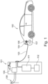
- FIG. 1 shows the charging station 101 and an electric car 102.
- a charging cable 103 is fixedly connected with the charging station 101 and couples the charging station with the electric car 102. At its free end the charging cable 103 is provided with a charging plug 104 plugged into a charging socket 106 of the electric car 102.
- the charging socket 106 is connected with a battery 107.
- the electric car 103 is only an example for any kind of electric vehicle, for instance a bike, a van, the truck or even a boat.
- the charging station 101 is connected to a public supply grid 108.
- An AC/DC converter 109 generates DC current for charging the electric car 102.
- a refrigerator apparatus 111 liquefies nitrogen from the atmosphere to supply it as coolant to the electric car 102 or to a cryogenic storage tank 112.
- the cryogenic storage tank 112 enables the charging station 101 to instantaneously provide very high cooling power.
- the cryogenic storage tank 112 can be dimensioned to satisfy the requested cooling power even in phases of high demand that significantly exceeds the amount of liquid nitrogen (LN2) that can continuously be generated by the refrigerator apparatus 111.
- LN2 liquid nitrogen
- Such high demand occurs for instance at the beginning of vacations when many people travel long distances and do not want to spend a lot of time at charging stations. Since LN2 can easily be stored in the cryogenic storage tank, the LN2 is preferably generated when there is an oversupply of electric energy supply grid.
- the interface for the cable charging plug 104 is standardized. In Europe the plug 104 is most frequently a so-called Type 2 connector ("Mennekes" plug) for AC charging or a CCS connector (also known as Combo 2 connector) for either AC or DC charging. Fast charging normally is performed by DC charging because in this case the charging station 101 can provide high DC currents allowing charging a battery of the electric car 102 with a charging power in the range of 50 kW to 350 kW. Such high charging power is linked with high currents that entail significant ohmic losses generating corresponding heating in the charging cable, the contacts of the charging plug and socket as well as in the cables inside the electric car connecting the charging socket 106 with the battery.
- a first option is to increase the diameter of the cable conductors and contacts.
- a second option is to actively cool the cable conductors and contacts. In addition to that it may also be necessary to cool the battery during fast charging.
- a disadvantage of the first option is that the charging cable becomes bulky and is not easy to handle.
- conductor material with the low ohmic resistance, such as copper is expensive as well as the additional amount of insulating material that is needed for thicker cables.
- Larger cable diameters inside a vehicle increase the weight of the vehicle, which is undesirable as well. For these reasons active cooling of components which are subject to ohmic heating during fast charging is superior regarding the mentioned aspects.
- FIG. 2 displays an embodiment of charging cable 103 which is labelled with reference number 200 in Figure 2 .
- the charging cable 200 comprises integrated cooling conduits 201a, 201b, which are helically wound around three electric lines 202 inside the charging cable 200.
- the electric lines 202 are in thermal contact with the cooling conduits 201a,201b for cooling purposes.
- the charging station 101 feeds recooled coolant into the cooling conduit 201a.
- the coolant returns to the charging station 101 through the cooling conduit 201b establishing a closed circuit for the coolant which is symbolized by arrow 203.
- the electric lines 202 are embedded into an inner sheath 204.
- An outer sheath 206 encloses the electric lines 202 and cooling conduits 201a, 201b providing electric and thermal insulation as well as mechanical protection.
- the charging plug must also enable transfer of coolant from the charging station 101 to the electric car 102.
- charging plugs that meet this requirement are not compatible with standardized Type 2 and CCS charging plugs most widely used in Europe.
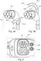
- FIG 3A shows a free end 301 of the charging cable 200 comprising a conventional plug 104.
- the plug 104 is connected with the electrical lines 202 inside the cable 200.
- the cooling conduits 201a, 201b are exiting from the outer sheath 206 of the charging cable 200 and are provided with hose couplings 302a, 302b enabling a fluid-tight connection for coolant to be circulated inside the electric car 102.
- the hose couplings 302a, 302b are closed unless connected with the corresponding counterpart preventing unintentional is capable of coolant.
- the plug 104 itself is not cooled which may present a limitation for the charging currents that can be transferred through the plug 104. This problem is addressed by a charging cable shown in Figure 3B .
- FIG 3B displays a further improved charging cable 200.
- the cooling conduits 201a, 201b enter jointly with the electric lines into the plug 104.
- the cooling conduits 201a, 201b supply coolant to the plug 104 and the contacts of the plug 104.
- the charging plug 104 is provided with cooling channels that are not shown in Figure 3B .
- the cooling conduits 201a, 201b exit from the plug and are closed at their ends with hose couplings 302a, 302b. In this way effective cooling of the charging plug 104 can be achieved.
- the plugs 104 shown in Figures 3A and 3B are compatible with any charging socket of an electric car that accepts the Type 2 plug of a charging cable. It is noted that the Type 2 charging plug is only a representative example of any other type of standardized charging plug.
- FIG. 4 shows a charging interface 400 of the electric car 102 comprising a CCS charging socket 401 and hose couplings 402a, 402b.
- the hose couplings 402a, 402b are in fluid connection with internal cooling conduits inside the electric car 102 cooling the electric lines connecting the charging socket 401 with a battery inside the electric car 102.
- the internal cooling conduits also cool parts of the battery that tend to heat up during fast charging.
- the charging cable 200 of the present disclosure can be used in combination with legacy electric cars which are not equipped with hose couplings 402a,402b. Since the hose couplings 302a, 302b remain to be close, the charging cable functions as a conventional charging cable without cooling functionality. However, in one embodiment the hose couplings 302a, 302b are connected with a connection piece enabling the closed cooling circuit within the charging cable 200. This approach allows reduced diameters of the electric lines 202 inside the charging cable 200 without compromising the magnitude of the charging current.
- the electric lines inside the electric car have a tubular structure enabling the coolant to flow inside the electric lines. In this way a particularly efficient cooling can be achieved.
- LN2 is transferred as coolant through the charging cable 103 to the electric car 102 enabling very efficient cooling of all current carrying components that tend to heat up during fast charging.
- the cooling capacity of LN2 is so big that the cooled components can be cooled down to temperatures way below ambient temperature in spite of the ohmic heating by the charging current.
- Low temperatures are advantageous because the resistance of the current carrying components normally decreases with decreasing temperatures.
- the charging cable 103 may become very stiff making it impossible to disconnect the charging cable 103 from the electric car 102. For this reason, a new charging method is proposed.
- a charging current and LN2 flows through the charging cable 103 to the electric car (step S2).
- the charging current flows through the electric lines 202 inside the charging cable 103 from the charging station to a battery of the electric car 102.
- the LN2 flows inside cooling conduits to cool down current carrying components in the charging cable and in the electric car. Temperature sensors measure temperatures of selected components of the electric car 102 and/or the charging cable 103 (step S3).
- Selected components are for instance the electric lines 202 of the charging cable 103, electrical contacts in the charging plug 104 and/or in the charging socket 401, electric lines connecting the charging socket 106 with the battery of the electric car, contacts at the battery and the battery itself to name only a few examples.
- the measured temperatures of the selected components are signaled to the charging station (step S4).
- the charging station 101 controls the level of the charging currents such that during charging temperatures of the selected components do not exceed predefined threshold temperatures (step S5).
- the transfer of LN2 is terminated before a charging level of the battery approaches a preset charging level (step S6). That means, the transfer of LN2 is terminated prior to the transfer of the charging current.
- the driver of the electric car 102 may decide that the charging level of 60% of the battery is sufficient to reach his destination. In this case the transfer of LN2 is terminated when the charging level of the battery has reached for instance 55%.
- the charging cable 103 Since the charging current continues to flow through the charging cable 103 until the charging level of the battery has reached 60%, the charging cable 103 is heated up by ohmic losses inside the charging cable. Thus, the charging cable 103 reaches temperatures at or above ambient temperatures when the charging of the battery is finished. As a result, the charging cable is flexible again and can easily be disconnected from the electric car 102.
- the same concept is applied to when the battery is fully charged, i.e. the transfer of LN2 is terminated when the battery charging level has reached e.g. 90% of the fully charged level.
- the mentioned charging levels are only examples and may be adapted in each specific application to achieve the goal of warming up the charging cable at the end of the charging process.
- the cooling conduits inside the charging cable 103 and the internal cooling conduits inside the electric car 100 to provide for an open circuit instead of a closed circuit described above. That means the LN2 flows unidirectional from the charging station 101 to the electric car 102 where it escapes into the environment.
- This embodiment requires less expenditures for the cooling conduits, the charging cable 103 becomes less bulky and on the side of the electric car 102 weight can be saved.
- a charging cable 200 provided with a supply cooling conduit 201a and a return cooling conduit 201b can be used in combination with an electric car offering only an open cooling circuit with a single hose coupling 402a. In this case the hose couplings 302b of the cooling conduit 201b remains to be closed.
- a single unit or device may perform the functions of multiple elements recited in the claims.
- the fact that individual functions and elements are recited in different dependent claims does not mean that a combination of those functions and elements could not advantageously be used.
Landscapes
- Engineering & Computer Science (AREA)
- Power Engineering (AREA)
- Transportation (AREA)
- Mechanical Engineering (AREA)
- Life Sciences & Earth Sciences (AREA)
- Sustainable Development (AREA)
- Sustainable Energy (AREA)
- Electric Propulsion And Braking For Vehicles (AREA)
- Charge And Discharge Circuits For Batteries Or The Like (AREA)
Abstract
A charging cable for an electric vehicle. The charging cable comprises at its free end (301) a charging plug (104) and electrical lines connecting the charging plug with a charging station. The electrical lines are in thermal contact with a cooling conduit. The cooling conduit is connectable at the free end of the charging cable with a fluid coupling (302a,302b) that is separate from the charging plug. Furthermore, a charging interface for accepting a charging plug of a charging cable is a suggested as well as a charging method for charging an electric car. The charging method is adapted for the use of liquid nitrogen as coolant for current carrying components.
Description
- The present disclosure relates to a charging cable, a charging interface, and a method for charging electric cars.
- Electric vehicles are more and more common. Apart from their limited electric range, the time that is required to recharge their battery is one of the major disadvantages compared to conventional cars with combustion engines, which can be refueled in a few minutes. Consequently, there is a desire to reduce the required charging time by increasing the electric charging power. At present, charging voltages are as high as 500 V for realizing a charging power of 50 kW. For further increasing the charging power, charging currents beyond 100 A need to be employed which generate significant heat in the charging cable connectors and in the battery of the electric car.
-
DE 10 2016 117 261 B3 describes a charging system with a fluid cooled charging cable. The coolant flows through with the cable up to the contacts of the charging plug and returns in a closed circuit back to a charging station that is equipped with a refrigerator apparatus for cooling the coolant back. Each contact of the charging plug is connected with one coaxial line carrying the electric current and providing the ducts for the cooling circuit. The coolant is not transferred to the charged car for cooling components in the car that also heat up during the charging process. -
DE 10 2010 007 975 A1 discloses charging station that is equipped with an integrated cooling apparatus. The charging station is connected with a charging cable and ducts for transporting coolant to the battery of the electric car. In one embodiment the charging cable and the ducts for the coolant form an integrated part. The electric lines and to the cooling conduits are connected with the car by means of a single integrated charging plug. One advantage of this approach is that the coolant also cools the charging cable and not only the battery in the car. In another embodiment of the charging station, compressed air is a used to cool of the battery by blowing the air over the battery. This cooling concept does not involve a closed-circuit. The embodiments that enable cooling the charging cable simultaneously with cooling the battery require an adapted charging plug. - Most electric cars in Europe are employed with so-called
Type 2 plugs ("Mennekes" plug) for AC charging or CCS-Type 2 plugs for AC and DC charging. These plugs do not provide for couplings for a coolant. - In view of the limitations of existing charging systems, there remains a desire for equipment that is compatible with existing electric cars but enables at the same time faster charging than with conventional charging cables and plugs.
- According to a first aspect the present disclosure suggests a charging cable for an electric vehicle. The charging cable comprises at its free end a charging plug and electrical lines connecting the charging plug (104) with a charging station. The electrical lines are in thermal contact with a cooling conduit. The cooling conduit is connectable at the free end of the charging cable with a fluid coupling that is separate from the charging plug.
- Due to the active cooling of the charging cable, it is possible to reduce the diameters of the electric lines inside the charging cable. The charging cable is less heavy and more flexible. At the same time material costs are reduced. The fluid coupling allows for connecting the fluid conduit to the corresponding fluid coupling at an electric car such that components inside the electric car can be cooled as well during fast charging. Since the fluid coupling is separate from the charging plug no change of standardized charging plugs is necessary. As a result, also conventional electric cars that cannot receive coolant for cooling current carrying components can be charged without any disadvantage with the charging cable proposed by the present disclosure.
- Advantageously, the charging plug is a standardized charging plug, in particular a
Type 2 or CCS charging plug. Thus, conventional electric cars are compatible with the suggested charging cable. - In a preferred embodiment the cooling conduit is configured to supply line for coolant. In this way, the charging cable enables transferring coolant to the connected electric car and cooling components of the electric car which heat up during fast charging. The cooling conduit is either part of a closed circuit for coolant or is a unidirectional supply line at the end of which the coolant escapes into the atmosphere. In either case effective cooling of components inside the charging cable and the electric car is performed. If the cooling conduit is a unidirectional supply line only, then the structure of the charging cable is simpler than compared with a closed circuit. At the same time the charging cable is easier to handle.
- In a further advantageous embodiment, the charging cable comprises a first cooling conduit functioning as a supply line for coolant from the charging station and a second cooling conduit functioning as a return line to the charging station.
- According to a second aspect of the present disclosure a charging interface for accepting a charging plug of a charging cable is a suggested. The charging interface comprises a charging socket accepting the charging plug and at least one fluid coupling spatially separated from the charging socket for receiving coolant. The charging interface is based on standardized charging sockets and charging plugs but at the same time provides for active cooling of current carrying components inside the electric car. The active cooling advantageously permits higher charging currents and thus reduces the time required for charging a battery of the electric car.
- According to preferred embodiments each cooling conduit and its associated fluid coupling are adapted to conduct liquid nitrogen as coolant. Liquid nitrogen is a very effective coolant that can be produced easily at low costs. The handling of liquid nitrogen presents no particular difficulties and entails no risk of environmental hazards.
- According to a third aspect of the present disclosure a method for charging an electric vehicle from a charging station is a suggested. The method comprises:
- establishing an electric connection and the fluid connection between the charging station and the electric car;
- transferring a charging current and liquid nitrogen through the charging cable from the charging station to the electric car;
- measuring temperatures of selected components of the electric car and/or the charging cable;
- signaling the measured temperatures to the charging station;
- controlling the level of the charging currents such that during charging of the electric car temperatures of the selected components do not exceed predefined threshold temperatures;
- terminating the transfer of liquid nitrogen prior to terminating the transfer of the charging current.
- Terminating the supply of coolant prior to terminating the transfer of the charging current enables warming up the charging cable before it needs to be disconnected from the electric car. Especially when liquid nitrogen is used this coolant, the charging cable becomes very stiff when the full cooling power of the liquid nitrogen is applied. In this state, the resistance of the charging cable is advantageously reduced but at the same time the charging cable cannot be handled easily or even not at all. The warm-up phase towards the end of the charging process prevents any handling problems when the charging cable needs to be disconnected from the electric car.
- According to a fourth aspect a charging station is suggested that provides, firstly, electric energy for charging an electric car and, secondly, liquid nitrogen as coolant for cooling current carrying components in a charging cable and/or the electric car. The charging station allows realizing the advantages that have already been mentioned in the context of the charging cable.
- Advantageously, the charging station comprises a refrigerator apparatus for generating liquid nitrogen and a storage tank for storing the liquid nitrogen. The storage tank allows for supplying a lot of cooling power without the need to die mentioned the refrigerator apparatus to the maximum expected demand of coolant. Rather, the refrigerator apparatus continuously generates liquid nitrogen as coolant for storing it in the storage tank. From the storage tank the liquid nitrogen can be supplied in large quantities to satisfy even peak demands for instance when many people are traveling at the same time seeking for the fastest possible charging of their electric car.
- Further advantages of the present disclosure will become apparent when reading the detailed description and the claims.
- Exemplary embodiments of the present disclosure are illustrated in the drawings and are explained in more detail in the following description. In the figures, the same or similar elements are referenced with the same or similar reference signs. It shows:
- Fig. 1
- a charging station with an electric car connected to the charging station;
- Fig. 2
- a charging cable with an integrated cooling coil forming a closed-circuit;
- Figs. 3A, 3B
- a charging plug of a charging cable according to the present disclosure;
- Fig. 4
- a socket for the charging plug shown in
Fig. 2 ; and - Fig. 5
- a schematic flow diagram of a method for charging an electric car according to the present disclosure.
- In the figures the same or similar components are labelled with the same or similar reference signs.
-
Figure 1 shows the chargingstation 101 and anelectric car 102. A chargingcable 103 is fixedly connected with the chargingstation 101 and couples the charging station with theelectric car 102. At its free end the chargingcable 103 is provided with a chargingplug 104 plugged into a chargingsocket 106 of theelectric car 102. The chargingsocket 106 is connected with abattery 107. It is noted that theelectric car 103 is only an example for any kind of electric vehicle, for instance a bike, a van, the truck or even a boat. - The charging
station 101 is connected to apublic supply grid 108. An AC/DC converter 109 generates DC current for charging theelectric car 102. Arefrigerator apparatus 111 liquefies nitrogen from the atmosphere to supply it as coolant to theelectric car 102 or to acryogenic storage tank 112. Thecryogenic storage tank 112 enables the chargingstation 101 to instantaneously provide very high cooling power. Thecryogenic storage tank 112 can be dimensioned to satisfy the requested cooling power even in phases of high demand that significantly exceeds the amount of liquid nitrogen (LN2) that can continuously be generated by therefrigerator apparatus 111. Such high demand occurs for instance at the beginning of vacations when many people travel long distances and do not want to spend a lot of time at charging stations. Since LN2 can easily be stored in the cryogenic storage tank, the LN2 is preferably generated when there is an oversupply of electric energy supply grid. - The interface for the
cable charging plug 104 is standardized. In Europe theplug 104 is most frequently a so-calledType 2 connector ("Mennekes" plug) for AC charging or a CCS connector (also known asCombo 2 connector) for either AC or DC charging. Fast charging normally is performed by DC charging because in this case the chargingstation 101 can provide high DC currents allowing charging a battery of theelectric car 102 with a charging power in the range of 50 kW to 350 kW. Such high charging power is linked with high currents that entail significant ohmic losses generating corresponding heating in the charging cable, the contacts of the charging plug and socket as well as in the cables inside the electric car connecting the chargingsocket 106 with the battery. For avoiding excessive heating of components during fast charging of the electric car, there are in principle two options. A first option is to increase the diameter of the cable conductors and contacts. A second option is to actively cool the cable conductors and contacts. In addition to that it may also be necessary to cool the battery during fast charging. - A disadvantage of the first option is that the charging cable becomes bulky and is not easy to handle. In addition to that, conductor material with the low ohmic resistance, such as copper, is expensive as well as the additional amount of insulating material that is needed for thicker cables. Larger cable diameters inside a vehicle increase the weight of the vehicle, which is undesirable as well. For these reasons active cooling of components which are subject to ohmic heating during fast charging is superior regarding the mentioned aspects.
-
Figure 2 displays an embodiment of chargingcable 103 which is labelled withreference number 200 inFigure 2 . The chargingcable 200 comprises integratedcooling conduits electric lines 202 inside the chargingcable 200. Theelectric lines 202 are in thermal contact with thecooling conduits station 101 feeds recooled coolant into thecooling conduit 201a. The coolant returns to the chargingstation 101 through thecooling conduit 201b establishing a closed circuit for the coolant which is symbolized byarrow 203. Theelectric lines 202 are embedded into aninner sheath 204. Anouter sheath 206 encloses theelectric lines 202 andcooling conduits - But if the active cooling shall not be limited to the charging
cable 200, then the charging plug must also enable transfer of coolant from the chargingstation 101 to theelectric car 102. However, charging plugs that meet this requirement are not compatible withstandardized Type 2 and CCS charging plugs most widely used in Europe. -
Figure 3A shows afree end 301 of the chargingcable 200 comprising aconventional plug 104. Theplug 104 is connected with theelectrical lines 202 inside thecable 200. Thecooling conduits outer sheath 206 of the chargingcable 200 and are provided withhose couplings electric car 102. Thehose couplings Figure 3A theplug 104 itself is not cooled which may present a limitation for the charging currents that can be transferred through theplug 104. This problem is addressed by a charging cable shown inFigure 3B . -
Figure 3B displays a further improved chargingcable 200. Thecooling conduits plug 104. Thecooling conduits plug 104 and the contacts of theplug 104. To this end, the chargingplug 104 is provided with cooling channels that are not shown inFigure 3B . Finally, thecooling conduits hose couplings plug 104 can be achieved. It is important to note that theplugs 104 shown inFigures 3A and 3B are compatible with any charging socket of an electric car that accepts theType 2 plug of a charging cable. It is noted that theType 2 charging plug is only a representative example of any other type of standardized charging plug. - In order to transfer coolant from a charging
station 101 to anelectric car 102 through the chargingcable 103 according to the present disclosure, it is sufficient to equip theelectric car 102 with hose couplings accepting thehose couplings cooling conduits Figure 4 shows a charginginterface 400 of theelectric car 102 comprising aCCS charging socket 401 andhose couplings hose couplings electric car 102 cooling the electric lines connecting the chargingsocket 401 with a battery inside theelectric car 102. In one embodiment the internal cooling conduits also cool parts of the battery that tend to heat up during fast charging. - It is emphasized that the charging
cable 200 of the present disclosure can be used in combination with legacy electric cars which are not equipped withhose couplings hose couplings hose couplings cable 200. This approach allows reduced diameters of theelectric lines 202 inside the chargingcable 200 without compromising the magnitude of the charging current. - In a further embodiment the electric lines inside the electric car have a tubular structure enabling the coolant to flow inside the electric lines. In this way a particularly efficient cooling can be achieved.
- In one embodiment LN2 is transferred as coolant through the charging
cable 103 to theelectric car 102 enabling very efficient cooling of all current carrying components that tend to heat up during fast charging. The cooling capacity of LN2 is so big that the cooled components can be cooled down to temperatures way below ambient temperature in spite of the ohmic heating by the charging current. Low temperatures are advantageous because the resistance of the current carrying components normally decreases with decreasing temperatures. However, at low temperatures the chargingcable 103 may become very stiff making it impossible to disconnect the chargingcable 103 from theelectric car 102. For this reason, a new charging method is proposed. - After the electric and fluid connections between the charging
station 101 and theelectric car 102 have been established (step S1) by means of the chargingcable 103, a charging current and LN2 flows through the chargingcable 103 to the electric car (step S2). Specifically, the charging current flows through theelectric lines 202 inside the chargingcable 103 from the charging station to a battery of theelectric car 102. The LN2 flows inside cooling conduits to cool down current carrying components in the charging cable and in the electric car. Temperature sensors measure temperatures of selected components of theelectric car 102 and/or the charging cable 103 (step S3). Selected components are for instance theelectric lines 202 of the chargingcable 103, electrical contacts in the chargingplug 104 and/or in the chargingsocket 401, electric lines connecting the chargingsocket 106 with the battery of the electric car, contacts at the battery and the battery itself to name only a few examples. - The measured temperatures of the selected components are signaled to the charging station (step S4). In response, the charging
station 101 controls the level of the charging currents such that during charging temperatures of the selected components do not exceed predefined threshold temperatures (step S5). The transfer of LN2 is terminated before a charging level of the battery approaches a preset charging level (step S6). That means, the transfer of LN2 is terminated prior to the transfer of the charging current. For example, the driver of theelectric car 102 may decide that the charging level of 60% of the battery is sufficient to reach his destination. In this case the transfer of LN2 is terminated when the charging level of the battery has reached for instance 55%. Since the charging current continues to flow through the chargingcable 103 until the charging level of the battery has reached 60%, the chargingcable 103 is heated up by ohmic losses inside the charging cable. Thus, the chargingcable 103 reaches temperatures at or above ambient temperatures when the charging of the battery is finished. As a result, the charging cable is flexible again and can easily be disconnected from theelectric car 102. The same concept is applied to when the battery is fully charged, i.e. the transfer of LN2 is terminated when the battery charging level has reached e.g. 90% of the fully charged level. Of course, the mentioned charging levels are only examples and may be adapted in each specific application to achieve the goal of warming up the charging cable at the end of the charging process. - In a further embodiment the cooling conduits inside the charging
cable 103 and the internal cooling conduits inside the electric car 100 to provide for an open circuit instead of a closed circuit described above. That means the LN2 flows unidirectional from the chargingstation 101 to theelectric car 102 where it escapes into the environment. This embodiment requires less expenditures for the cooling conduits, the chargingcable 103 becomes less bulky and on the side of theelectric car 102 weight can be saved. Of course, a chargingcable 200 provided with asupply cooling conduit 201a and areturn cooling conduit 201b can be used in combination with an electric car offering only an open cooling circuit with asingle hose coupling 402a. In this case thehose couplings 302b of thecooling conduit 201b remains to be closed. - In the claims, the word "comprising" does not exclude other elements or steps, and the indefinite article "a" does not exclude a plurality.
- A single unit or device may perform the functions of multiple elements recited in the claims. The fact that individual functions and elements are recited in different dependent claims does not mean that a combination of those functions and elements could not advantageously be used.
-
- 101
- charging station
- 102
- electric car
- 103
- charging cable
- 104
- charging plug
- 106
- charging socket
- 107
- battery
- 108
- supply grid
- 109
- AC/DC converter
- 111
- refrigerator apparatus
- 112
- cryogenic storage tank
- 201a,201b
- cooling conduit
- 202
- electric line
- 203
- arrow
- 204
- inner sheath
- 206
- outer sheath
- 301
- free end of charging cable
- 302a, 302b
- hose couplings
- 400
- charging interface
- 401
- charging socket
- 402a,402b
- hose couplings
Claims (9)
- Charging cable for an electric vehicle(102), wherein the charging cable (103,200) comprises at its free end (301) a charging plug (104) and electrical lines (202) connecting the charging plug (104) with a charging station (101), wherein the electrical lines (202) are in thermal contact with a cooling conduit (201a,201b), characterized in that the cooling conduit (201a,201b) is connectable at the free end of the charging cable with a fluid coupling (302a,302b) that is separate from the charging plug (104).
- Charging cable according to claim 1, wherein the charging plug (104) is a standardized charging plug, in particular a Type 2 or CCS charging plug.
- Charging cable according to claims 1 or 2, wherein the cooling conduit (201a,201b) is configured to supply line for a coolant.
- Charging cable according to one of the preceding claims, wherein the charging cable (103) comprises a first cooling conduit (201a) functioning as a supply line for coolant from the charging station and a second cooling conduit (201b) functioning as a return line to the charging station (101).
- Interface for accepting a charging plug of a charging cable, characterized in that the charging interface (400) comprises a charging socket (401) accepting the charging plug (104) and at least one fluid coupling spatially separated from the charging socket for (401) receiving coolant.
- Charging cable or interface according to one of the preceding claims, wherein each cooling conduit (201a,201b) and its associated fluid coupling (302a,302b) are adapted to conduct liquid nitrogen as coolant.
- Method for charging an electric vehicle (102) from a charging station (101), wherein the method comprises:- establishing (step S1) an electric connection and the fluid connection between the charging station and the electric vehicle (102);- transferring (step S2) a charging current and liquid nitrogen through the charging cable (103) from the charging station to the electric car;- measuring (step S3) temperatures of selected components of the electric car and/or the charging cable;- signaling (step S4) the measured temperatures to the charging station (101);- controlling (step S5) the level of the charging currents such that during charging of the electric car (102) temperatures of the selected components do not exceed predefined threshold temperatures;- terminating (step S6) the transfer of liquid nitrogen prior to terminating the transfer of the charging current.
- Charging station providing electric energy for charging an electric car (102) and for providing liquid nitrogen as coolant for cooling current carrying components in a charging cable (103) and/or the electric car.
- Charging station according to claim 8, wherein the charging station (101) comprises a refrigerator apparatus (111) for generating liquid nitrogen and a storage tank (112) for storing the liquid nitrogen.
Priority Applications (1)
| Application Number | Priority Date | Filing Date | Title |
|---|---|---|---|
| EP22305019.6A EP4210175A1 (en) | 2022-01-11 | 2022-01-11 | Charging cable, charging interface and method for charging electric cars |
Applications Claiming Priority (1)
| Application Number | Priority Date | Filing Date | Title |
|---|---|---|---|
| EP22305019.6A EP4210175A1 (en) | 2022-01-11 | 2022-01-11 | Charging cable, charging interface and method for charging electric cars |
Publications (1)
| Publication Number | Publication Date |
|---|---|
| EP4210175A1 true EP4210175A1 (en) | 2023-07-12 |
Family
ID=80113216
Family Applications (1)
| Application Number | Title | Priority Date | Filing Date |
|---|---|---|---|
| EP22305019.6A Withdrawn EP4210175A1 (en) | 2022-01-11 | 2022-01-11 | Charging cable, charging interface and method for charging electric cars |
Country Status (1)
| Country | Link |
|---|---|
| EP (1) | EP4210175A1 (en) |
Citations (6)
| Publication number | Priority date | Publication date | Assignee | Title |
|---|---|---|---|---|
| DE102010007975A1 (en) | 2010-02-15 | 2011-08-18 | Siemens Aktiengesellschaft, 80333 | Loading station for e.g. accumulator of electric car, has cooling device that is provided with cooling conduit, which is connected to car for supplying coolant e.g. gas such as air or nitrogen, to electrical energy storage of car |
| US9233618B2 (en) * | 2011-07-25 | 2016-01-12 | Lightening Energy | Station for rapidly charging an electric vehicle battery |
| DE102016117261B3 (en) | 2016-09-14 | 2017-11-30 | HARTING Automotive GmbH | System consisting of a connector, a fluid-cooled cable and a connection unit |
| KR102028369B1 (en) * | 2019-05-24 | 2019-10-04 | 한국전력공사 | Apparatus for charging electric vehicle using supercontuctive cable |
| US20200391601A1 (en) * | 2019-06-14 | 2020-12-17 | Honda Motor Co., Ltd. | Electric vehicle cooling system |
| WO2022006352A1 (en) * | 2020-07-02 | 2022-01-06 | Electric Power Systems, Inc. | Hot charging systems and methods |
-
2022
- 2022-01-11 EP EP22305019.6A patent/EP4210175A1/en not_active Withdrawn
Patent Citations (6)
| Publication number | Priority date | Publication date | Assignee | Title |
|---|---|---|---|---|
| DE102010007975A1 (en) | 2010-02-15 | 2011-08-18 | Siemens Aktiengesellschaft, 80333 | Loading station for e.g. accumulator of electric car, has cooling device that is provided with cooling conduit, which is connected to car for supplying coolant e.g. gas such as air or nitrogen, to electrical energy storage of car |
| US9233618B2 (en) * | 2011-07-25 | 2016-01-12 | Lightening Energy | Station for rapidly charging an electric vehicle battery |
| DE102016117261B3 (en) | 2016-09-14 | 2017-11-30 | HARTING Automotive GmbH | System consisting of a connector, a fluid-cooled cable and a connection unit |
| KR102028369B1 (en) * | 2019-05-24 | 2019-10-04 | 한국전력공사 | Apparatus for charging electric vehicle using supercontuctive cable |
| US20200391601A1 (en) * | 2019-06-14 | 2020-12-17 | Honda Motor Co., Ltd. | Electric vehicle cooling system |
| WO2022006352A1 (en) * | 2020-07-02 | 2022-01-06 | Electric Power Systems, Inc. | Hot charging systems and methods |
Similar Documents
| Publication | Publication Date | Title |
|---|---|---|
| US11760217B2 (en) | Liquid cooled charging cable system | |
| US11465519B2 (en) | Electric vehicle charge equipment | |
| US11804315B2 (en) | EV charging cable system with cooling | |
| US20220144115A1 (en) | Electrical Vehicle Charging System for Charging an Electrical Vehicle | |
| EP4004953B1 (en) | Heavy-current charging cable for charging an electric vehicle | |
| US11433773B2 (en) | Charging harness unit for a battery of a motor vehicle | |
| US12334233B2 (en) | Cooled charging cable | |
| WO2021014009A1 (en) | Heavy-current charging cable for charging an electric vehicle | |
| WO2024037232A1 (en) | Charging terminal | |
| CN110869238A (en) | Electrical storage device for supplying electrical energy to at least one electrically drivable motor vehicle during a charging/discharging process, and retrofit module and operating method | |
| EP0715391B1 (en) | Environmentally controlled high power high frequency transmission cable for reductive charger | |
| JP6554023B2 (en) | Internal cooling cable | |
| EP4210175A1 (en) | Charging cable, charging interface and method for charging electric cars | |
| US20240149732A1 (en) | Control method and control unit for a charging process for an electric vehicle | |
| US20220001760A1 (en) | Charging arrangement for supplying electrical energy to an electrical vehicle | |
| US20240355507A1 (en) | Tube with spokes | |
| US20250222801A1 (en) | Lower loss charging cable | |
| EP4506205A1 (en) | Superconductors for ev chargers | |
| US20180206364A1 (en) | Arrangement for supplying power to a motor vehicle equipped with an electric motor |
Legal Events
| Date | Code | Title | Description |
|---|---|---|---|
| PUAI | Public reference made under article 153(3) epc to a published international application that has entered the european phase |
Free format text: ORIGINAL CODE: 0009012 |
|
| STAA | Information on the status of an ep patent application or granted ep patent |
Free format text: STATUS: THE APPLICATION HAS BEEN PUBLISHED |
|
| AK | Designated contracting states |
Kind code of ref document: A1 Designated state(s): AL AT BE BG CH CY CZ DE DK EE ES FI FR GB GR HR HU IE IS IT LI LT LU LV MC MK MT NL NO PL PT RO RS SE SI SK SM TR |
|
| STAA | Information on the status of an ep patent application or granted ep patent |
Free format text: STATUS: THE APPLICATION IS DEEMED TO BE WITHDRAWN |
|
| 18D | Application deemed to be withdrawn |
Effective date: 20240113 |