EP4210156A1 - Secondary battery - Google Patents
Secondary battery Download PDFInfo
- Publication number
- EP4210156A1 EP4210156A1 EP23150258.4A EP23150258A EP4210156A1 EP 4210156 A1 EP4210156 A1 EP 4210156A1 EP 23150258 A EP23150258 A EP 23150258A EP 4210156 A1 EP4210156 A1 EP 4210156A1
- Authority
- EP
- European Patent Office
- Prior art keywords
- electrode
- plate
- current collector
- terminal
- coupling protrusion
- Prior art date
- Legal status (The legal status is an assumption and is not a legal conclusion. Google has not performed a legal analysis and makes no representation as to the accuracy of the status listed.)
- Pending
Links
Images


Classifications
-
- H—ELECTRICITY
- H01—ELECTRIC ELEMENTS
- H01M—PROCESSES OR MEANS, e.g. BATTERIES, FOR THE DIRECT CONVERSION OF CHEMICAL ENERGY INTO ELECTRICAL ENERGY
- H01M50/00—Constructional details or processes of manufacture of the non-active parts of electrochemical cells other than fuel cells, e.g. hybrid cells
- H01M50/50—Current conducting connections for cells or batteries
- H01M50/531—Electrode connections inside a battery casing
- H01M50/533—Electrode connections inside a battery casing characterised by the shape of the leads or tabs
-
- H—ELECTRICITY
- H01—ELECTRIC ELEMENTS
- H01M—PROCESSES OR MEANS, e.g. BATTERIES, FOR THE DIRECT CONVERSION OF CHEMICAL ENERGY INTO ELECTRICAL ENERGY
- H01M4/00—Electrodes
- H01M4/02—Electrodes composed of, or comprising, active material
- H01M4/64—Carriers or collectors
- H01M4/70—Carriers or collectors characterised by shape or form
-
- H—ELECTRICITY
- H01—ELECTRIC ELEMENTS
- H01M—PROCESSES OR MEANS, e.g. BATTERIES, FOR THE DIRECT CONVERSION OF CHEMICAL ENERGY INTO ELECTRICAL ENERGY
- H01M50/00—Constructional details or processes of manufacture of the non-active parts of electrochemical cells other than fuel cells, e.g. hybrid cells
- H01M50/10—Primary casings; Jackets or wrappings
- H01M50/102—Primary casings; Jackets or wrappings characterised by their shape or physical structure
- H01M50/103—Primary casings; Jackets or wrappings characterised by their shape or physical structure prismatic or rectangular
-
- H—ELECTRICITY
- H01—ELECTRIC ELEMENTS
- H01M—PROCESSES OR MEANS, e.g. BATTERIES, FOR THE DIRECT CONVERSION OF CHEMICAL ENERGY INTO ELECTRICAL ENERGY
- H01M50/00—Constructional details or processes of manufacture of the non-active parts of electrochemical cells other than fuel cells, e.g. hybrid cells
- H01M50/10—Primary casings; Jackets or wrappings
- H01M50/131—Primary casings; Jackets or wrappings characterised by physical properties, e.g. gas permeability, size or heat resistance
- H01M50/133—Thickness
-
- H—ELECTRICITY
- H01—ELECTRIC ELEMENTS
- H01M—PROCESSES OR MEANS, e.g. BATTERIES, FOR THE DIRECT CONVERSION OF CHEMICAL ENERGY INTO ELECTRICAL ENERGY
- H01M50/00—Constructional details or processes of manufacture of the non-active parts of electrochemical cells other than fuel cells, e.g. hybrid cells
- H01M50/10—Primary casings; Jackets or wrappings
- H01M50/147—Lids or covers
- H01M50/148—Lids or covers characterised by their shape
- H01M50/15—Lids or covers characterised by their shape for prismatic or rectangular cells
-
- H—ELECTRICITY
- H01—ELECTRIC ELEMENTS
- H01M—PROCESSES OR MEANS, e.g. BATTERIES, FOR THE DIRECT CONVERSION OF CHEMICAL ENERGY INTO ELECTRICAL ENERGY
- H01M50/00—Constructional details or processes of manufacture of the non-active parts of electrochemical cells other than fuel cells, e.g. hybrid cells
- H01M50/10—Primary casings; Jackets or wrappings
- H01M50/172—Arrangements of electric connectors penetrating the casing
- H01M50/174—Arrangements of electric connectors penetrating the casing adapted for the shape of the cells
- H01M50/176—Arrangements of electric connectors penetrating the casing adapted for the shape of the cells for prismatic or rectangular cells
-
- H—ELECTRICITY
- H01—ELECTRIC ELEMENTS
- H01M—PROCESSES OR MEANS, e.g. BATTERIES, FOR THE DIRECT CONVERSION OF CHEMICAL ENERGY INTO ELECTRICAL ENERGY
- H01M50/00—Constructional details or processes of manufacture of the non-active parts of electrochemical cells other than fuel cells, e.g. hybrid cells
- H01M50/50—Current conducting connections for cells or batteries
- H01M50/528—Fixed electrical connections, i.e. not intended for disconnection
-
- H—ELECTRICITY
- H01—ELECTRIC ELEMENTS
- H01M—PROCESSES OR MEANS, e.g. BATTERIES, FOR THE DIRECT CONVERSION OF CHEMICAL ENERGY INTO ELECTRICAL ENERGY
- H01M50/00—Constructional details or processes of manufacture of the non-active parts of electrochemical cells other than fuel cells, e.g. hybrid cells
- H01M50/50—Current conducting connections for cells or batteries
- H01M50/531—Electrode connections inside a battery casing
-
- H—ELECTRICITY
- H01—ELECTRIC ELEMENTS
- H01M—PROCESSES OR MEANS, e.g. BATTERIES, FOR THE DIRECT CONVERSION OF CHEMICAL ENERGY INTO ELECTRICAL ENERGY
- H01M50/00—Constructional details or processes of manufacture of the non-active parts of electrochemical cells other than fuel cells, e.g. hybrid cells
- H01M50/50—Current conducting connections for cells or batteries
- H01M50/531—Electrode connections inside a battery casing
- H01M50/536—Electrode connections inside a battery casing characterised by the method of fixing the leads to the electrodes, e.g. by welding
-
- H—ELECTRICITY
- H01—ELECTRIC ELEMENTS
- H01M—PROCESSES OR MEANS, e.g. BATTERIES, FOR THE DIRECT CONVERSION OF CHEMICAL ENERGY INTO ELECTRICAL ENERGY
- H01M50/00—Constructional details or processes of manufacture of the non-active parts of electrochemical cells other than fuel cells, e.g. hybrid cells
- H01M50/50—Current conducting connections for cells or batteries
- H01M50/543—Terminals
- H01M50/547—Terminals characterised by the disposition of the terminals on the cells
- H01M50/55—Terminals characterised by the disposition of the terminals on the cells on the same side of the cell
-
- H—ELECTRICITY
- H01—ELECTRIC ELEMENTS
- H01M—PROCESSES OR MEANS, e.g. BATTERIES, FOR THE DIRECT CONVERSION OF CHEMICAL ENERGY INTO ELECTRICAL ENERGY
- H01M50/00—Constructional details or processes of manufacture of the non-active parts of electrochemical cells other than fuel cells, e.g. hybrid cells
- H01M50/50—Current conducting connections for cells or batteries
- H01M50/543—Terminals
- H01M50/552—Terminals characterised by their shape
- H01M50/553—Terminals adapted for prismatic, pouch or rectangular cells
-
- H—ELECTRICITY
- H01—ELECTRIC ELEMENTS
- H01M—PROCESSES OR MEANS, e.g. BATTERIES, FOR THE DIRECT CONVERSION OF CHEMICAL ENERGY INTO ELECTRICAL ENERGY
- H01M50/00—Constructional details or processes of manufacture of the non-active parts of electrochemical cells other than fuel cells, e.g. hybrid cells
- H01M50/50—Current conducting connections for cells or batteries
- H01M50/543—Terminals
- H01M50/564—Terminals characterised by their manufacturing process
- H01M50/566—Terminals characterised by their manufacturing process by welding, soldering or brazing
-
- H—ELECTRICITY
- H01—ELECTRIC ELEMENTS
- H01M—PROCESSES OR MEANS, e.g. BATTERIES, FOR THE DIRECT CONVERSION OF CHEMICAL ENERGY INTO ELECTRICAL ENERGY
- H01M50/00—Constructional details or processes of manufacture of the non-active parts of electrochemical cells other than fuel cells, e.g. hybrid cells
- H01M50/50—Current conducting connections for cells or batteries
- H01M50/543—Terminals
- H01M50/564—Terminals characterised by their manufacturing process
- H01M50/567—Terminals characterised by their manufacturing process by fixing means, e.g. screws, rivets or bolts
-
- Y—GENERAL TAGGING OF NEW TECHNOLOGICAL DEVELOPMENTS; GENERAL TAGGING OF CROSS-SECTIONAL TECHNOLOGIES SPANNING OVER SEVERAL SECTIONS OF THE IPC; TECHNICAL SUBJECTS COVERED BY FORMER USPC CROSS-REFERENCE ART COLLECTIONS [XRACs] AND DIGESTS
- Y02—TECHNOLOGIES OR APPLICATIONS FOR MITIGATION OR ADAPTATION AGAINST CLIMATE CHANGE
- Y02E—REDUCTION OF GREENHOUSE GAS [GHG] EMISSIONS, RELATED TO ENERGY GENERATION, TRANSMISSION OR DISTRIBUTION
- Y02E60/00—Enabling technologies; Technologies with a potential or indirect contribution to GHG emissions mitigation
- Y02E60/10—Energy storage using batteries
-
- Y—GENERAL TAGGING OF NEW TECHNOLOGICAL DEVELOPMENTS; GENERAL TAGGING OF CROSS-SECTIONAL TECHNOLOGIES SPANNING OVER SEVERAL SECTIONS OF THE IPC; TECHNICAL SUBJECTS COVERED BY FORMER USPC CROSS-REFERENCE ART COLLECTIONS [XRACs] AND DIGESTS
- Y02—TECHNOLOGIES OR APPLICATIONS FOR MITIGATION OR ADAPTATION AGAINST CLIMATE CHANGE
- Y02P—CLIMATE CHANGE MITIGATION TECHNOLOGIES IN THE PRODUCTION OR PROCESSING OF GOODS
- Y02P70/00—Climate change mitigation technologies in the production process for final industrial or consumer products
- Y02P70/50—Manufacturing or production processes characterised by the final manufactured product
Definitions
- aspects of embodiments of the present disclosure relate to a secondary battery.
- secondary batteries are designed to be charged and discharged.
- Low-capacity secondary batteries are widely employed in small sized portable electronic devices, such as mobile phones, camcorders, etc.
- large-capacity secondary batteries are typically used for driving motors of hybrid automobiles, electric automobiles, etc.
- Such secondary batteries are manufactured in various shapes, and typical shapes include a cylindrical shape and a prismatic shape.
- the secondary battery is configured by installing an electrode assembly formed by interposing a separator, which is an insulator, between positive and negative electrode plates in a case with an electrolyte and installing a cap plate on the case.
- the electrode assembly is electrically connected to an electrode terminal through a current collector plate.
- the usable internal volume of the case e.g., the internal volume of the case available to accommodate active material
- Embodiments of the present disclosure provide a secondary battery exhibiting improved welding quality while maintaining the rigidity and heat tolerating performance of a current collector plate.
- a secondary battery includes: a case having an accommodating space therein; an electrode assembly accommodated in the case and having an uncoated portion on one end thereof; a current collector plate electrically connected to the uncoated portion of the electrode assembly; a cap plate sealing the case; and an electrode terminal (extending) outside the cap plate and electrically connected to the current collector plate.
- the current collector plate has a terminal hole through which the electrode terminal passes and the current collector plate includes a coupling protrusion protruding from the current collector plate toward the electrode assembly along a periphery of the terminal hole.
- the electrode terminal may be electrically connected to the current collector plate via the coupling protrusion.
- the electrode terminal may be electrically connected to the coupling protrusion in order to electrically connect the current collector plate.
- a rivet groove may be formed inside the coupling protrusion.
- a lower portion of the electrode terminal may be riveted to (i.e. deformed into) the rivet groove.
- a lower portion of the electrode terminal may be at least partially directly coupled with the coupling protrusion inside the rivet groove. That is, a lower portion of the electrode terminal may at least partially protrude into the rivet groove in order to be (electrically) coupled and interlocked with the coupling protrusion.
- the electrode terminal may be (directly) coupled to the coupling protrusion through welding.
- the electrode terminal may be welded to the coupling protrusion.
- a welding beam, used for the welding, may be irradiated upwardly from a lower surface of the coupling protrusion.
- a center of the welding beam may be positioned inside the coupling protrusion.
- the current collector plate may comprise a terminal connection portion and an electrode connection portion.
- Said terminal connection portion may comprise a plate portion extending in a direction parallel to the electrode assembly.
- the coupling protrusion may be formed on a lower surface of the plate portion. The coupling protrusion may protrude from the plate portion toward the electrode assembly along a periphery of the terminal hole.
- the current collector plate may have a plate portion extending in a direction parallel to the electrode assembly, and the coupling protrusion may be on a lower surface of the plate portion.
- a height (h) at which the coupling protrusion protrudes from the lower surface of the plate portion may be in a range of about 0.2*t1 ⁇ h ⁇ t1, and t1 may be the thickness of the plate portion.
- the width (t2) of the coupling protrusion along the lower surface of the plate portion may be in a range of about 0.2*t1 ⁇ t2 ⁇ t1, and t1 may be the thickness of the plate portion.
- the rivet groove in the coupling protrusion may have a width in a range of about 0.1 mm to about 0.2 mm in a direction parallel to a longitudinal direction of the electrode assembly.
- the rivet groove in the coupling protrusion may have a height in a range of about 0.2 mm to about 0.4 mm in a direction perpendicular to the longitudinal direction of the electrode assembly.
- a second aspect of the disclosure refers to a method of manufacturing the secondary battery as described above.
- the method comprises providing a case having an accommodating space therein, with an electrode assembly accommodated in the case and having an uncoated portion on one end thereof, with a current collector plate electrically connected to the uncoated portion of the electrode assembly, with a cap plate sealing the case, and with an electrode terminal (extending) outside the cap plate, wherein the current collector plate has a terminal hole through which the electrode terminal passes and the current collector plate includes a coupling protrusion protruding from the current collector plate toward the electrode assembly along a periphery of the terminal hole.
- the method further comprises electrically connecting the electrode terminal with the current collector plate.
- the electrode terminal may be electrically connected with the coupling protrusion in order to electrically connecting the electrode terminal with the current collector plate.
- the electrically connecting of the electrode terminal with the current collector plate may be performed by welding.
- the electrically connecting of the electrode terminal with the current collector plate may be performed by welding the electrode terminal to the coupling protrusion.
- the welding may be performed upwardly from a lower surface of the coupling protrusion.
- the method may further comprise before the welding, positioning a center of a welding beam inside the coupling protrusion.
- the method may further comprise, before the welding, deforming a lower riveting portion of the electrode terminal, as to couple an end portion of the lower riveting portion with the coupling protrusion inside the rivet groove.
- the deforming may be performed in a riveting-process, wherein the electrode terminal corresponds to a rivet.
- first, second, third, etc. may be used herein to describe various elements, components, regions, layers, and/or sections, these elements, components, regions, layers, and/or sections should not be limited by these terms. These terms are used to distinguish one element, component, region, layer, or section from another element, component, region, layer, or section. Thus, a first element, component, region, layer, or section discussed below could be termed a second element, component, region, layer, or section without departing from the teachings of example embodiments.
- spatially relative terms such as “beneath,” “below,” “lower,” “above,” “upper,” and the like, may be used herein for ease of description to describe one element or feature's relationship to another element(s) or feature(s) as illustrated in the figures. It will be understood that the spatially relative terms are intended to encompass different orientations of the device in use or operation in addition to the orientation depicted in the figures. For example, if the device in the figures is turned over, elements described as “below” or “beneath” other elements or features would then be oriented “above” or “over” the other elements or features. Thus, the term “below” may encompass both an orientation of above and below. The device may be otherwise oriented (rotated 90 degrees or at other orientations), and the spatially relative descriptors used herein should be interpreted accordingly.
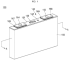
- FIG. 1 is a perspective view of a secondary battery according to an embodiment of the present disclosure.
- FIG. 2 is a cross-sectional view taken along the line A-A of FIG. 1 .
- FIG. 3 is an enlarged view of the portion B of FIG. 2 .
- FIG. 4 illustrates a terminal coupling portion of a current collector plate according to an embodiment of the present disclosure.
- a secondary battery 100 includes an electrode assembly 110, current collector plates 120 and 130, a case 150, and a cap assembly 160.
- the electrode assembly 110 is formed by stacking a plurality of layers of a first electrode plate, a separator, and a second electrode plate, each of which is formed in a thin plate shape or a film shape.
- the first electrode plate may be a first-polarity electrode, for example, a positive electrode
- the second electrode plate may be a second-polarity electrode, for example, a negative electrode.
- the first electrode plate and the second electrode plate may have any polarity as long as the polarities are different from each other.
- the first electrode plate is formed by coating a first electrode active material, such as a transition metal oxide, on a first electrode current collector formed of a metal foil, such as aluminum, and includes a first electrode uncoated portion 111, that is, a region to which the first active material is not applied.
- the first electrode uncoated portion 111 provides a passage for current flow between the first electrode plate and the outside.
- the first electrode uncoated portions 111 of the various first electrode plates are arranged and/or formed to overlap (e.g., to be aligned) at the same position when first electrode plates are stacked to form a multi-tap structure.
- the first electrode uncoated portion 111 is formed to protrude toward (or from) one side of the electrode assembly 110, and in some embodiments, a plurality of first uncoated portions 111 may be welded to each other to form one first current collecting tab.
- the first electrode uncoated portion 111 is aligned at the one side of the electrode assembly 110 and protrudes therefrom.
- the second electrode plate is formed by coating a second electrode active material, such as graphite or carbon, on a first electrode current collector formed of a metal foil, such as copper or nickel, and includes a second electrode uncoated portion 112, that is, a region to which the second active material is not applied.
- a second electrode active material such as graphite or carbon
- the second electrode uncoated portions 112 of the various first electrode plates are arranged and/or formed to overlap (e.g., to be aligned) at the same position when second electrode plates are stacked to form a multi-tap structure.
- the second electrode uncoated portion 112 is formed to protrude toward (or from) the other side of the electrode assembly 110, and in some embodiments, a plurality of second uncoated portions 112 may be welded to each other to form one second current collecting tab.
- the separator is positioned between the first electrode plate and the second electrode plate to prevent a short circuit while enabling movement of lithium ions.
- the separator may be made of polyethylene, polypropylene, or a composite film of polyethylene and polypropylene. However, the scope of the present disclosure is not limited by a material of the separator.
- the electrode assembly 110 may maintain a stacked state while a separate insulating tape 113 is attached to a partial region of the electrode assembly 110.
- the insulating tape 113 helps maintain the shape of the electrode assembly 110.
- the electrode assembly 110 can be welded to the current collector plates 120 and 130 at a correct position, and the structure of the electrode assembly 110 can be maintained in a final secondary battery structure.
- the electrode assembly 110 is substantially accommodated in the case 150 together with an electrolyte.
- the electrolyte may be formed of a lithium salt, such as LiPF 6 or LiBF 4 , in an organic solvent, such as ethylene carbonate (EC), propylene carbonate (PC), diethyl carbonate (DEC), ethyl methyl carbonate (EMC), or dimethyl carbonate (DMC).
- EC ethylene carbonate
- PC propylene carbonate
- DEC diethyl carbonate
- EMC ethyl methyl carbonate
- DMC dimethyl carbonate
- the electrolyte may be in the form of a liquid, a solid, or a gel.
- the current collector plates 120 and 130 include a first current collector plate 120 electrically connected to the first electrode uncoated portion 111 and a second current collector plate 130 electrically connected to the second electrode uncoated portion 112.
- the first current collector plate 120 is formed of a conductive material, such as aluminum, and is coupled to the first electrode uncoated portion 111 protruding to (or from) one end of the electrode assembly 110 to be electrically connected to the first electrode plate.
- the first current collector plate 120 may include an electrode connection portion 121 and a terminal connection portion 125.
- the electrode connection portion 121 and the terminal connection portion 125 may be directly coupled through welding.
- the electrode connection portion 121 may be directly welded to the terminal connection portion 125.
- the electrode connection portion 121 may be formed in (e.g., may primarily extend in) the vertical direction along one side surface of the electrode assembly 110.
- the electrode connection portion 121 may be coupled, through welding, in a state of being in contact with the first electrode uncoated portion 111 of the electrode assembly 110 and may have the same first polarity as the first electrode uncoated portion 111.
- the terminal connection portion 125 is positioned on the electrode assembly 110 and is formed in (e.g., extends primarily in) parallel with a cap plate 161, to be described later.
- the terminal connection portion 125 is positioned between the electrode assembly 110 and the cap plate 161 and has a substantially flat plate shape.
- the terminal connection portion 125 may be (directly) coupled to the electrode connection portion 121 through welding.
- the terminal connection portion 125 may include a rectangular plate portion 125a formed in parallel with the cap plate, a bent portion 125b provided at one end (or one edge) of the plate portion 125a, and a coupling protrusion 125c downwardly formed on the inner side (e.g., a side facing toward the electrode assembly 110) of the plate portion 125a.
- the plate portion 125a may be formed substantially parallel to the cap plate 161 and the electrode assembly 110.
- the plate portion 125a may be spaced apart from the electrode assembly 110 and may be separated from the cap plate 161 by an insulating member 170, to be described later. Accordingly, the plate portion 125a may be electrically independent of (e.g., electrically isolated from) the cap plate.
- the bent portion 125b may be provided at one end of the plate portion 125a.
- the bent portion 125b may be bent at about 90 degrees from the plate portion 125a and may be formed to face (e.g., to extend) downwardly. Accordingly, the bent portion 125b may be disposed in a direction parallel to the electrode connection portion 121, that is, along a longitudinal direction of the electrode uncoated portions 111 and 112 of the electrode assembly 110. Accordingly, the bent portion 125b may be coupled, through welding, in a state of being in contact with the electrode connection portion 121. In other words, the bent portion 125b may be in direct contact with the electrode uncoated portion 111 (112) and may be welded to the electrode connection portion 121.
- the coupling protrusion 125c may be formed at a lower portion of the plate portion 125a facing the electrode assembly 110 along the circumference (e.g., the periphery) of a terminal hole (e.g., an opening) formed in (or through) the plate portion 125a.
- the coupling protrusion 125c may protrude from the current collector plate, e.g. from the plate portion 125a, toward the electrode assembly along the edge of the terminal hole.
- the coupling protrusion 125c allows electrically connecting, e.g. by welding, the electrode terminal with the current collector plate a welding beam without damage of other components of the secondary battery.
- a thickness of the coupling protrusion 125c may be a distance the coupling protrusion 125c protrudes from the plate portion 125a.
- the upper insulating member 170 and the gasket 166 may not be damaged by the welding beam w (see, e.g., FIG. 3 ) because the welding beam w does not reach the upper portion of the plate portion 125a.
- the insulating member 170 and/or the gasket 166 do not undergo dielectric breakdown, and thus, electrical separation between the cap plate 161 and the plate portion 125a can be maintained.
- the height h, at which the coupling protrusion 125c protrudes, may be in a range of about 0.2*t1 ⁇ h ⁇ t1, compared to the thickness t1 of the plate portion 125a.
- the welding beam w may not reach the insulating member 170, and when the height h of the coupling protrusion 125c is less than or equal to about t1, the total terminal coupling portion 125 may be reduced, thereby securing (or providing) further space for the electrode assembly 110 in the case 150.
- the width t2 of the coupling protrusion 125c may also be in a range of about 0.2*t1 ⁇ t2 ⁇ t1, compared to the thickness t1 of the plate portion 125a.
- the width t2 of the coupling protrusion 125c is greater than or equal to about 0.2*t1, the width thereof may be greater than the width of the welding beam w, and thus, the welding beam w may not deviate from the coupling protrusion 125c in the horizontal direction.
- the width t2 of the coupling protrusion 125c is less than or equal to about the thickness t1, the plate portion 125a may be easily manufactured by performing punch processing, and the weight of the terminal coupling portion 125 can be reduced.
- the center of the welding beam w in the horizontal direction may be located (or positioned) inside the coupling protrusion 125c. Accordingly, the welding beam w is irradiated around the inside of the coupling protrusion 125c rather than at the boundary between the coupling protrusion 125c and the first electrode terminal 164, thus, the welding beam w does not reach the insulating member 170 and/or the gasket 166 along the boundary.
- a rivet groove 125d to which the first electrode terminal 164 is rivet-coupled, may be formed at an inner lower portion of the coupling protrusion 125c.
- the rivet groove 125d may be formed along the circumference of the inner hole of the coupling protrusion 125c and may be a ring-shaped groove. In other words, the rivet groove 125d may be formed along the inner surface of the coupling protrusion 125c that faces the electrode terminal.
- the rivet groove 125d may have a width in a range of about 0.1 mm to about 0.2 mm in the horizontal direction and a height in a range of about 0.2 mm to about 0.4 mm in the vertical direction.
- the aforesaid width in horizontal direction may be understood as the depth of the rivet groove with which it reaches into the coupling protrusion 125c.
- the width of the rivet groove 125d is greater than or equal to about 0.1 mm, preferably greater than or equal to about 0.12 mm, preferably greater than or equal to about 0.14 mm, the first electrode terminal 164 is securely fastened, and when the width of the rivet groove 125d is less than or equal to about 0.2 mm, preferably less than or equal to about 0.18 mm, preferably less than or equal to about 0.16 mm, the end of the first electrode terminal 164 is positioned in a central region of the welding beam w in the horizontal direction, and thus, stable welding can be performed.
- the first electrode terminal 164 may not be detached from the rivet groove 125d after welding, and when the height of the rivet groove 125d is less than or equal to about 0.4 mm, the terminal of the first electrode terminal 164 may be located inside the welding beam w in the vertical direction, thereby determining (e.g., controlling) the depth of the welding beam w.
- the height of the rivet groove 125d is greater than or equal to about 0.3 mm.
- the height of the rivet groove 125d is less than or equal to about 0.35 mm.
- the second current collector plate 130 is made of a conductive material, such as nickel, and is in contact with the second electrode uncoated portion 112 protruding from the other end of the electrode assembly 110 to be electrically connected to the second electrode plate.
- the second current collector plate 130 includes an electrode connection portion 131 and a terminal connection portion 135. However, because the shape of the second current collector plate 130 is the same (or substantially the same) as that of the first current collector plate 120, a repeated description thereof will be omitted.
- the case 150 is made of a conductive metal, such as aluminum, an aluminum alloy, or nickel-plated steel, and has a substantially hexahedral shape in which an opening through which the electrode assembly 110 can be inserted and seated is formed.
- the cap plate 161 is coupled to the opening (e.g., along a periphery of the opening) in the case 150 to seal the case 150.
- the inner surface of the case 150 is insulated to prevent an electrical short circuit from occurring therein.
- one electrode of the electrode assembly 110 may be electrically connected to the case 150 through the cap plate 161. Even in such an embodiment, an electrical short circuit inside the case 150 is prevented by the insulation treatment.
- the case 150 may act as a first electrode, for example, a positive electrode.
- the cap assembly 160 is coupled to an upper portion of (e.g., the opening in) the case 150.
- the cap assembly 160 includes a cap plate 161, an electrolyte injection hole (e.g., an electrolyte injection opening) 162, a safety vent 163, a first electrode terminal 164, a second electrode terminal 165, a gasket 166, a first electrode terminal plate 167, a second electrode terminal plate 168, a fastening plate 169, and an insulating member 170.
- the cap plate 161 seals the opening in the case 150 and may be formed of the same material as the case 150.
- the cap plate 161 may be coupled to the case 150 by laser welding.
- the cap plate 161 may be electrically independent or, in some embodiments, may be electrically connected to either the first current collector plate 120 or the second current collector plate 130.
- the cap plate 161 may have a protrusion (e.g., a groove) 161a protruding downwardly at a terminal periphery to fix the position of the insulating member 170 coupled thereto.
- the electrolyte injection hole 162 for injecting an electrolyte is formed in the cap plate 161.
- the electrolyte is injected into the inside of the case 150 through the electrolyte injection hole 162, and thereafter, the electrolyte injection hole 162 is sealed by a stopper.
- the safety vent 163 is formed to have a relatively thin thickness compared to other regions of the cap plate 161 and is formed at approximately the center of the cap plate 161. When the internal pressure of the case 150 is higher than a set breaking (or rupture) pressure, the safety vent 163 ruptures to prevent the secondary battery 100 from exploding.
- the first electrode terminal 164 and the second electrode terminal 165 are respectively formed (or installed) to pass through the cap plate 161.
- the first electrode terminal 164 is coupled to a terminal hole (e.g., a terminal opening) formed in the terminal connection portion 125 of the first current collector plate 120 to be electrically connected to the first current collector plate 120.
- the second electrode terminal 165 is coupled to a terminal hole (e.g., a terminal opening) formed in the terminal connection portion 135 of the second current collector plate 120 to be electrically connected to the second current collector plate 130.
- the first electrode terminal 164 may include a terminal body 164a, a flange portion 164d, a lower riveting portion 164b, and an upper riveting portion 164e.
- the terminal body 164a may have a substantially cylindrical shape.
- the terminal body 164a may be coupled to the upper portion of the cap plate 161 through the flange portion 164d and a fastening plate 169 may be formed therebetween to achieve electrical separation.
- the lower riveting portion 164b may be formed under the terminal body 164a.
- the lower riveting portion 164b may be deformed through a riveting process, and thus, an end portion 164c thereof may be coupled into the rivet groove 125d.
- the welding beam w may be applied. Through this process, the end portion 164c of the lower riveting portion 164b may be electrically and physically coupled to the terminal coupling portion 125 of the current collector plate 120.
- the upper riveting portion 164e may be deformed through riveting on the upper surface of the first terminal plate 167 to be coupled to the first terminal plate 167. Accordingly, the first electrode terminal 164 is electrically connected to the first uncoated portion 111 of the electrode assembly 110 through the current collector plate 120 and is connected to the first terminal plate 167 disposed outside, thereby forming a current path.
- the second electrode terminal 165 may have the same shape as the first electrode terminal 164, and, for convenience, a detailed description of the second electrode terminal 165 will be omitted.
- the gasket 166 is formed (or installed) between the first and second electrode terminals 164 and 165 and the cap plate 161.
- the gasket 166 surrounds (e.g., extends around a periphery of) the outside of each of the first and second terminals 164 and 165 and is made of an insulating material.
- the gasket 166 seals portions between the first and second electrode terminals 164 and 165 and the cap plate.
- the gasket 166 prevents external moisture from penetrating into the secondary battery 100 and/or prevents the electrolyte contained in the secondary battery 100 from leaking to the outside.
- the first terminal plate 167 is coupled to the first electrode terminal 164 protruding above the cap plate 161. After the first terminal plate 167 is coupled to the first electrode terminal 164, an upper portion of the first electrode terminal 164 may be riveted or a boundary surface between the first terminal plate 167 and the first electrode terminal 164 may be welded. Thus, the first terminal plate 167 may be fixed to the first electrode terminal 164.
- the second electrode terminal plate 168 is coupled to the second electrode terminal 165 protruding to an upper portion of (e.g., protruding above an upper surface of) the cap plate 161. After the second electrode terminal plate 168 is coupled to the second electrode terminal 165, the upper portion of the second electrode terminal 165 may be riveted or the boundary surface between the second electrode terminal plate 168 and the second electrode terminal 165 may be welded. Thus, the second electrode terminal plate 168 may be fixed to the second electrode terminal 165.
- the fastening plate 169 is formed (or installed) between the cap plate 161 and the first terminal plate 167 and between the cap plate 161 and the second electrode terminal plate 168.
- the fastening plate 169 may be formed of either an electrically conductive material or an insulating material.
- the fastening plate 169 positioned under the first terminal plate 167 may be made of a conductive material and the fastening plate 169 positioned under the second electrode terminal plate 168 may be made of an insulating material.
- the fastening plate 169 is made of an insulating material, the first electrode terminal 164 and the second electrode terminal 165 may be electrically separated from the cap plate 161.
- the insulating member 170 is formed between the first current collector plate 120 and the cap plate 161 and between the second current collector plate 130 and the cap plate 161 such that the first and second current collector plates 120 and 130 and the cap plate 161 are electrically insulated from each other.
- the welding beam w does not reach the insulating member 170 and/or the gasket 166, and thus, the insulating member 170 and/or the gasket 166 may not be damaged.
- the coupling protrusion 125c protruding downwardly toward the electrode assembly 110 is provided in the periphery of a terminal hole through which the electrode terminals 164 and 165 pass, and welding is performed when the electrode terminals 164 and 165 are coupled along the rivet groove 125d formed inside the coupling protrusion 125c.
- the welding beam w may not reach the insulating member 170 and/or the gasket 166 located above the current collector plates 120 and 130, thereby preventing the insulating member 170 and/or the gasket 166 from being damaged.
- the method comprises providing a case 150 having an accommodating space therein, with an electrode assembly 110 accommodated in the case 150 and having an uncoated portion on 111 one end thereof, with a current collector plate 120 electrically connected to the uncoated portion 111 of the electrode assembly 110, with a cap plate 161 sealing the case 150, and with an electrode terminal 164 (extending) outside the cap plate 161, wherein the current collector plate 120 has a terminal hole through which the electrode terminal 164 passes and the current collector plate 120 includes a coupling protrusion 125c protruding from the current collector plate 120 toward the electrode assembly 110 along a periphery of the terminal hole.
- the method further comprises electrically connecting the electrode terminal 164 with the current collector plate 120.
- the electrode terminal 164 may be directly (electrically) connected with the coupling protrusion 125c in order to electrically connecting the electrode terminal 164 with the current collector plate 120.
- the electrically connecting of the electrode terminal 164 with the current collector plate 120 may be performed by welding.
- the electrically connecting of the electrode terminal 164 with the current collector plate 120 may be performed by welding the electrode terminal 164 to the coupling protrusion 125c.
- the welding may be performed upwardly from a lower surface of the coupling protrusion 125c.
- the method may further comprise before the welding, positioning a center of a welding beam inside the coupling protrusion 125c.
- the method may further comprise, before the welding, deforming a lower riveting portion 164b of the electrode terminal 164 as to couple an end portion 164c of the lower riveting portion 164 b with the coupling protrusion 125c inside the rivet groove 125d.
- the deforming may be performed in a riveting-process, wherein the electrode terminal corresponds to a rivet.
- the current collector plate includes a coupling protrusion protruding downwardly, and welding is performed when an electrode terminal is coupled along a rivet groove formed inside the coupling protrusion so that welding beam(s) may not reach an insulating member and/or a gasket located above the current collector plate, thereby preventing the insulating member and/or the gasket from being damaged.
Landscapes
- Chemical & Material Sciences (AREA)
- Chemical Kinetics & Catalysis (AREA)
- Electrochemistry (AREA)
- General Chemical & Material Sciences (AREA)
- Engineering & Computer Science (AREA)
- Manufacturing & Machinery (AREA)
- Connection Of Batteries Or Terminals (AREA)
Abstract
A secondary battery includes: a case having an accommodating space therein; an electrode assembly accommodated in the case and having an uncoated portion on one end thereof; a current collector plate electrically connected to the uncoated portion of the electrode assembly; a cap plate sealing the case; and an electrode terminal outside the cap plate and electrically connected to the current collector plate. The current collector plate has a terminal hole through which the electrode terminal passes and the current collector plate includes a coupling protrusion protruding toward the electrode assembly along a periphery of the terminal hole.
Description
- Aspects of embodiments of the present disclosure relate to a secondary battery.
- Different from primary batteries, which are not designed to be rechargeable, secondary batteries are designed to be charged and discharged. Low-capacity secondary batteries are widely employed in small sized portable electronic devices, such as mobile phones, camcorders, etc., and large-capacity secondary batteries are typically used for driving motors of hybrid automobiles, electric automobiles, etc.
- Such secondary batteries are manufactured in various shapes, and typical shapes include a cylindrical shape and a prismatic shape. The secondary battery is configured by installing an electrode assembly formed by interposing a separator, which is an insulator, between positive and negative electrode plates in a case with an electrolyte and installing a cap plate on the case. The electrode assembly is electrically connected to an electrode terminal through a current collector plate. The usable internal volume of the case (e.g., the internal volume of the case available to accommodate active material) changes according to the structure of the current collector plate.
- Embodiments of the present disclosure provide a secondary battery exhibiting improved welding quality while maintaining the rigidity and heat tolerating performance of a current collector plate.
- A secondary battery, according to an embodiment of the present disclosure, includes: a case having an accommodating space therein; an electrode assembly accommodated in the case and having an uncoated portion on one end thereof; a current collector plate electrically connected to the uncoated portion of the electrode assembly; a cap plate sealing the case; and an electrode terminal (extending) outside the cap plate and electrically connected to the current collector plate. The current collector plate has a terminal hole through which the electrode terminal passes and the current collector plate includes a coupling protrusion protruding from the current collector plate toward the electrode assembly along a periphery of the terminal hole.
- The electrode terminal may be electrically connected to the current collector plate via the coupling protrusion. For example, the electrode terminal may be electrically connected to the coupling protrusion in order to electrically connect the current collector plate.
- In an embodiment of the secondary battery, a rivet groove may be formed inside the coupling protrusion. Also, a lower portion of the electrode terminal may be riveted to (i.e. deformed into) the rivet groove. In other words, a lower portion of the electrode terminal may be at least partially directly coupled with the coupling protrusion inside the rivet groove. That is, a lower portion of the electrode terminal may at least partially protrude into the rivet groove in order to be (electrically) coupled and interlocked with the coupling protrusion.
- The electrode terminal may be (directly) coupled to the coupling protrusion through welding. The electrode terminal may be welded to the coupling protrusion.
- A welding beam, used for the welding, may be irradiated upwardly from a lower surface of the coupling protrusion.
- A center of the welding beam may be positioned inside the coupling protrusion.
- In an embodiment, the current collector plate may comprise a terminal connection portion and an electrode connection portion. Said terminal connection portion may comprise a plate portion extending in a direction parallel to the electrode assembly. The coupling protrusion may be formed on a lower surface of the plate portion. The coupling protrusion may protrude from the plate portion toward the electrode assembly along a periphery of the terminal hole.
- The current collector plate may have a plate portion extending in a direction parallel to the electrode assembly, and the coupling protrusion may be on a lower surface of the plate portion.
- A height (h) at which the coupling protrusion protrudes from the lower surface of the plate portion may be in a range of about 0.2*t1 ≤ h ≤ t1, and t1 may be the thickness of the plate portion.
- The width (t2) of the coupling protrusion along the lower surface of the plate portion may be in a range of about 0.2*t1 ≤ t2 ≤ t1, and t1 may be the thickness of the plate portion.
- The rivet groove in the coupling protrusion may have a width in a range of about 0.1 mm to about 0.2 mm in a direction parallel to a longitudinal direction of the electrode assembly.
- The rivet groove in the coupling protrusion may have a height in a range of about 0.2 mm to about 0.4 mm in a direction perpendicular to the longitudinal direction of the electrode assembly.
- A second aspect of the disclosure refers to a method of manufacturing the secondary battery as described above.
- The method comprises providing a case having an accommodating space therein, with an electrode assembly accommodated in the case and having an uncoated portion on one end thereof, with a current collector plate electrically connected to the uncoated portion of the electrode assembly, with a cap plate sealing the case, and with an electrode terminal (extending) outside the cap plate, wherein the current collector plate has a terminal hole through which the electrode terminal passes and the current collector plate includes a coupling protrusion protruding from the current collector plate toward the electrode assembly along a periphery of the terminal hole. The method further comprises electrically connecting the electrode terminal with the current collector plate.
- In one embodiment of the method, the electrode terminal may be electrically connected with the coupling protrusion in order to electrically connecting the electrode terminal with the current collector plate.
- In the method, the electrically connecting of the electrode terminal with the current collector plate may be performed by welding. Preferably, the electrically connecting of the electrode terminal with the current collector plate may be performed by welding the electrode terminal to the coupling protrusion. Preferably, the welding may be performed upwardly from a lower surface of the coupling protrusion.
- The method may further comprise before the welding, positioning a center of a welding beam inside the coupling protrusion.
- The method may further comprise, before the welding, deforming a lower riveting portion of the electrode terminal, as to couple an end portion of the lower riveting portion with the coupling protrusion inside the rivet groove. The deforming may be performed in a riveting-process, wherein the electrode terminal corresponds to a rivet.
-
-
FIG. 1 is a perspective view of a secondary battery according to an embodiment of the present disclosure. -
FIG. 2 is a cross-sectional view taken along the line A-A ofFIG. 1 . -
FIG. 3 is an enlarged view of the portion B ofFIG. 2 . -
FIG. 4 illustrates a terminal coupling portion of a current collector plate according to an embodiment of the present disclosure. - Hereinafter, embodiments of the present disclosure will be described, in detail, with reference to the accompanying drawings.
- Embodiments of the present disclosure are provided herein to more completely explain the present disclosure, but the present disclosure may be embodied in many different forms and should not be construed as being limited to the embodiments set forth herein. Rather, these example embodiments are provided so that this disclosure will be thorough and complete and will convey the aspects and features of the present disclosure to a person skilled in the art.
- It will be understood that when an element or layer is referred to as being "on," "connected to," or "coupled to" another element or layer, it may be directly on, connected, or coupled to the other element or layer or one or more intervening elements or layers may also be present. When an element or layer is referred to as being "directly on," "directly connected to," or "directly coupled to" another element or layer, there are no intervening elements or layers present. For example, when a first element is described as being "coupled" or "connected" to a second element, the first element may be directly coupled or connected to the second element or the first element may be indirectly coupled or connected to the second element via one or more intervening elements.
- In the figures, dimensions of the various elements, layers, etc. may be exaggerated for clarity of illustration. The same reference numerals designate the same elements. As used herein, the term "and/or" includes any and all combinations of one or more of the associated listed items. Further, the use of "may" when describing embodiments of the present disclosure relates to "one or more embodiments of the present disclosure." Expressions, such as "at least one of," when preceding a list of elements, modify the entire list of elements and do not modify the individual elements of the list. As used herein, the terms "use," "using," and "used" may be considered synonymous with the terms "utilize," "utilizing," and "utilized," respectively. As used herein, the terms "substantially," "about," and similar terms are used as terms of approximation and not as terms of degree, and are intended to account for the inherent variations in measured or calculated values that would be recognized by those of ordinary skill in the art.
- It will be understood that, although the terms first, second, third, etc. may be used herein to describe various elements, components, regions, layers, and/or sections, these elements, components, regions, layers, and/or sections should not be limited by these terms. These terms are used to distinguish one element, component, region, layer, or section from another element, component, region, layer, or section. Thus, a first element, component, region, layer, or section discussed below could be termed a second element, component, region, layer, or section without departing from the teachings of example embodiments.
- Spatially relative terms, such as "beneath," "below," "lower," "above," "upper," and the like, may be used herein for ease of description to describe one element or feature's relationship to another element(s) or feature(s) as illustrated in the figures. It will be understood that the spatially relative terms are intended to encompass different orientations of the device in use or operation in addition to the orientation depicted in the figures. For example, if the device in the figures is turned over, elements described as "below" or "beneath" other elements or features would then be oriented "above" or "over" the other elements or features. Thus, the term "below" may encompass both an orientation of above and below. The device may be otherwise oriented (rotated 90 degrees or at other orientations), and the spatially relative descriptors used herein should be interpreted accordingly.
- The terminology used herein is for the purpose of describing embodiments of the present disclosure and is not intended to be limiting of the present disclosure. As used herein, the singular forms "a" and "an" are intended to include the plural forms as well, unless the context clearly indicates otherwise. It will be further understood that the terms "includes," "including," "comprises," and/or "comprising," when used in this specification, specify the presence of stated features, integers, steps, operations, elements, and/or components but do not preclude the presence or addition of one or more other features, integers, steps, operations, elements, components, and/or groups thereof.
-
FIG. 1 is a perspective view of a secondary battery according to an embodiment of the present disclosure.FIG. 2 is a cross-sectional view taken along the line A-A ofFIG. 1 .FIG. 3 is an enlarged view of the portion B ofFIG. 2 .FIG. 4 illustrates a terminal coupling portion of a current collector plate according to an embodiment of the present disclosure. - Referring to
FIGS. 1 to 4 , asecondary battery 100, according to an embodiment of the present disclosure, includes anelectrode assembly 110,current collector plates case 150, and acap assembly 160. - The
electrode assembly 110 is formed by stacking a plurality of layers of a first electrode plate, a separator, and a second electrode plate, each of which is formed in a thin plate shape or a film shape. In one embodiment, the first electrode plate may be a first-polarity electrode, for example, a positive electrode, and the second electrode plate may be a second-polarity electrode, for example, a negative electrode. However, in other embodiments, the first electrode plate and the second electrode plate may have any polarity as long as the polarities are different from each other. - The first electrode plate is formed by coating a first electrode active material, such as a transition metal oxide, on a first electrode current collector formed of a metal foil, such as aluminum, and includes a first electrode
uncoated portion 111, that is, a region to which the first active material is not applied. The first electrodeuncoated portion 111 provides a passage for current flow between the first electrode plate and the outside. - The first electrode
uncoated portions 111 of the various first electrode plates are arranged and/or formed to overlap (e.g., to be aligned) at the same position when first electrode plates are stacked to form a multi-tap structure. The first electrodeuncoated portion 111 is formed to protrude toward (or from) one side of theelectrode assembly 110, and in some embodiments, a plurality of firstuncoated portions 111 may be welded to each other to form one first current collecting tab. The first electrodeuncoated portion 111 is aligned at the one side of theelectrode assembly 110 and protrudes therefrom. - The second electrode plate is formed by coating a second electrode active material, such as graphite or carbon, on a first electrode current collector formed of a metal foil, such as copper or nickel, and includes a second electrode
uncoated portion 112, that is, a region to which the second active material is not applied. - The second electrode
uncoated portions 112 of the various first electrode plates are arranged and/or formed to overlap (e.g., to be aligned) at the same position when second electrode plates are stacked to form a multi-tap structure. The second electrodeuncoated portion 112 is formed to protrude toward (or from) the other side of theelectrode assembly 110, and in some embodiments, a plurality of seconduncoated portions 112 may be welded to each other to form one second current collecting tab. - The separator is positioned between the first electrode plate and the second electrode plate to prevent a short circuit while enabling movement of lithium ions. The separator may be made of polyethylene, polypropylene, or a composite film of polyethylene and polypropylene. However, the scope of the present disclosure is not limited by a material of the separator.
- After the plurality of electrode plates are stacked, the
electrode assembly 110 may maintain a stacked state while a separateinsulating tape 113 is attached to a partial region of theelectrode assembly 110. The insulatingtape 113 helps maintain the shape of theelectrode assembly 110. Thus, theelectrode assembly 110 can be welded to thecurrent collector plates electrode assembly 110 can be maintained in a final secondary battery structure. - The
electrode assembly 110 is substantially accommodated in thecase 150 together with an electrolyte. The electrolyte may be formed of a lithium salt, such as LiPF6 or LiBF4, in an organic solvent, such as ethylene carbonate (EC), propylene carbonate (PC), diethyl carbonate (DEC), ethyl methyl carbonate (EMC), or dimethyl carbonate (DMC). In addition, the electrolyte may be in the form of a liquid, a solid, or a gel. - The
current collector plates current collector plate 120 electrically connected to the first electrodeuncoated portion 111 and a secondcurrent collector plate 130 electrically connected to the second electrodeuncoated portion 112. - The first
current collector plate 120 is formed of a conductive material, such as aluminum, and is coupled to the first electrodeuncoated portion 111 protruding to (or from) one end of theelectrode assembly 110 to be electrically connected to the first electrode plate. - The first
current collector plate 120 may include anelectrode connection portion 121 and aterminal connection portion 125. In some embodiments, theelectrode connection portion 121 and theterminal connection portion 125 may be directly coupled through welding. In other words, theelectrode connection portion 121 may be directly welded to theterminal connection portion 125. - The
electrode connection portion 121 may be formed in (e.g., may primarily extend in) the vertical direction along one side surface of theelectrode assembly 110. Theelectrode connection portion 121 may be coupled, through welding, in a state of being in contact with the first electrodeuncoated portion 111 of theelectrode assembly 110 and may have the same first polarity as the first electrodeuncoated portion 111. - The
terminal connection portion 125 is positioned on theelectrode assembly 110 and is formed in (e.g., extends primarily in) parallel with acap plate 161, to be described later. For example, theterminal connection portion 125 is positioned between theelectrode assembly 110 and thecap plate 161 and has a substantially flat plate shape. Theterminal connection portion 125 may be (directly) coupled to theelectrode connection portion 121 through welding. - Referring to
FIGS. 3 and 4 , theterminal connection portion 125 may include arectangular plate portion 125a formed in parallel with the cap plate, abent portion 125b provided at one end (or one edge) of theplate portion 125a, and acoupling protrusion 125c downwardly formed on the inner side (e.g., a side facing toward the electrode assembly 110) of theplate portion 125a. - The
plate portion 125a may be formed substantially parallel to thecap plate 161 and theelectrode assembly 110. Theplate portion 125a may be spaced apart from theelectrode assembly 110 and may be separated from thecap plate 161 by an insulatingmember 170, to be described later. Accordingly, theplate portion 125a may be electrically independent of (e.g., electrically isolated from) the cap plate. - The
bent portion 125b may be provided at one end of theplate portion 125a. Thebent portion 125b may be bent at about 90 degrees from theplate portion 125a and may be formed to face (e.g., to extend) downwardly. Accordingly, thebent portion 125b may be disposed in a direction parallel to theelectrode connection portion 121, that is, along a longitudinal direction of the electrodeuncoated portions electrode assembly 110. Accordingly, thebent portion 125b may be coupled, through welding, in a state of being in contact with theelectrode connection portion 121. In other words, thebent portion 125b may be in direct contact with the electrode uncoated portion 111 (112) and may be welded to theelectrode connection portion 121. - The
coupling protrusion 125c may be formed at a lower portion of theplate portion 125a facing theelectrode assembly 110 along the circumference (e.g., the periphery) of a terminal hole (e.g., an opening) formed in (or through) theplate portion 125a. In other words, thecoupling protrusion 125c may protrude from the current collector plate, e.g. from theplate portion 125a, toward the electrode assembly along the edge of the terminal hole. Thecoupling protrusion 125c allows electrically connecting, e.g. by welding, the electrode terminal with the current collector plate a welding beam without damage of other components of the secondary battery. A thickness of thecoupling protrusion 125c may be a distance thecoupling protrusion 125c protrudes from theplate portion 125a. - Therefore, when the
first electrode terminal 164 is welded in a subsequent process, the upper insulatingmember 170 and thegasket 166 may not be damaged by the welding beam w (see, e.g.,FIG. 3 ) because the welding beam w does not reach the upper portion of theplate portion 125a. As a result, the insulatingmember 170 and/or thegasket 166 do not undergo dielectric breakdown, and thus, electrical separation between thecap plate 161 and theplate portion 125a can be maintained. - The height h, at which the
coupling protrusion 125c protrudes, may be in a range of about 0.2*t1 ≤ h ≤ t1, compared to the thickness t1 of theplate portion 125a. When the height h of thecoupling protrusion 125c is greater than or equal to about 0.2*t1, the welding beam w may not reach the insulatingmember 170, and when the height h of thecoupling protrusion 125c is less than or equal to about t1, the totalterminal coupling portion 125 may be reduced, thereby securing (or providing) further space for theelectrode assembly 110 in thecase 150. - In addition, the width t2 of the
coupling protrusion 125c may also be in a range of about 0.2*t1 ≤t2≤t1, compared to the thickness t1 of theplate portion 125a. When the width t2 of thecoupling protrusion 125c is greater than or equal to about 0.2*t1, the width thereof may be greater than the width of the welding beam w, and thus, the welding beam w may not deviate from thecoupling protrusion 125c in the horizontal direction. In addition, when the width t2 of thecoupling protrusion 125c is less than or equal to about the thickness t1, theplate portion 125a may be easily manufactured by performing punch processing, and the weight of theterminal coupling portion 125 can be reduced. - The center of the welding beam w in the horizontal direction may be located (or positioned) inside the
coupling protrusion 125c. Accordingly, the welding beam w is irradiated around the inside of thecoupling protrusion 125c rather than at the boundary between thecoupling protrusion 125c and thefirst electrode terminal 164, thus, the welding beam w does not reach the insulatingmember 170 and/or thegasket 166 along the boundary. - A
rivet groove 125d, to which thefirst electrode terminal 164 is rivet-coupled, may be formed at an inner lower portion of thecoupling protrusion 125c. Therivet groove 125d may be formed along the circumference of the inner hole of thecoupling protrusion 125c and may be a ring-shaped groove. In other words, therivet groove 125d may be formed along the inner surface of thecoupling protrusion 125c that faces the electrode terminal. Therivet groove 125d may have a width in a range of about 0.1 mm to about 0.2 mm in the horizontal direction and a height in a range of about 0.2 mm to about 0.4 mm in the vertical direction. The aforesaid width in horizontal direction may be understood as the depth of the rivet groove with which it reaches into thecoupling protrusion 125c. When the width of therivet groove 125d is greater than or equal to about 0.1 mm, preferably greater than or equal to about 0.12 mm, preferably greater than or equal to about 0.14 mm, thefirst electrode terminal 164 is securely fastened, and when the width of therivet groove 125d is less than or equal to about 0.2 mm, preferably less than or equal to about 0.18 mm, preferably less than or equal to about 0.16 mm, the end of thefirst electrode terminal 164 is positioned in a central region of the welding beam w in the horizontal direction, and thus, stable welding can be performed. When the height of therivet groove 125d is greater than or equal to about 0.2 mm, thefirst electrode terminal 164 may not be detached from therivet groove 125d after welding, and when the height of therivet groove 125d is less than or equal to about 0.4 mm, the terminal of thefirst electrode terminal 164 may be located inside the welding beam w in the vertical direction, thereby determining (e.g., controlling) the depth of the welding beam w. Preferably, the height of therivet groove 125d is greater than or equal to about 0.3 mm. Preferably, the height of therivet groove 125d is less than or equal to about 0.35 mm. - The second
current collector plate 130 is made of a conductive material, such as nickel, and is in contact with the second electrodeuncoated portion 112 protruding from the other end of theelectrode assembly 110 to be electrically connected to the second electrode plate. The secondcurrent collector plate 130 includes anelectrode connection portion 131 and aterminal connection portion 135. However, because the shape of the secondcurrent collector plate 130 is the same (or substantially the same) as that of the firstcurrent collector plate 120, a repeated description thereof will be omitted. - The
case 150 is made of a conductive metal, such as aluminum, an aluminum alloy, or nickel-plated steel, and has a substantially hexahedral shape in which an opening through which theelectrode assembly 110 can be inserted and seated is formed. Thecap plate 161 is coupled to the opening (e.g., along a periphery of the opening) in thecase 150 to seal thecase 150. The inner surface of thecase 150 is insulated to prevent an electrical short circuit from occurring therein. In some embodiments, one electrode of theelectrode assembly 110 may be electrically connected to thecase 150 through thecap plate 161. Even in such an embodiment, an electrical short circuit inside thecase 150 is prevented by the insulation treatment. Thecase 150 may act as a first electrode, for example, a positive electrode. - The
cap assembly 160 is coupled to an upper portion of (e.g., the opening in) thecase 150. For example, thecap assembly 160 includes acap plate 161, an electrolyte injection hole (e.g., an electrolyte injection opening) 162, asafety vent 163, afirst electrode terminal 164, asecond electrode terminal 165, agasket 166, a firstelectrode terminal plate 167, a secondelectrode terminal plate 168, afastening plate 169, and an insulatingmember 170. - The
cap plate 161 seals the opening in thecase 150 and may be formed of the same material as thecase 150. For example, thecap plate 161 may be coupled to thecase 150 by laser welding. In addition, thecap plate 161 may be electrically independent or, in some embodiments, may be electrically connected to either the firstcurrent collector plate 120 or the secondcurrent collector plate 130. Thecap plate 161 may have a protrusion (e.g., a groove) 161a protruding downwardly at a terminal periphery to fix the position of the insulatingmember 170 coupled thereto. - The
electrolyte injection hole 162 for injecting an electrolyte is formed in thecap plate 161. The electrolyte is injected into the inside of thecase 150 through theelectrolyte injection hole 162, and thereafter, theelectrolyte injection hole 162 is sealed by a stopper. - The
safety vent 163 is formed to have a relatively thin thickness compared to other regions of thecap plate 161 and is formed at approximately the center of thecap plate 161. When the internal pressure of thecase 150 is higher than a set breaking (or rupture) pressure, thesafety vent 163 ruptures to prevent thesecondary battery 100 from exploding. - The
first electrode terminal 164 and thesecond electrode terminal 165 are respectively formed (or installed) to pass through thecap plate 161. Thefirst electrode terminal 164 is coupled to a terminal hole (e.g., a terminal opening) formed in theterminal connection portion 125 of the firstcurrent collector plate 120 to be electrically connected to the firstcurrent collector plate 120. Similarly, thesecond electrode terminal 165 is coupled to a terminal hole (e.g., a terminal opening) formed in theterminal connection portion 135 of the secondcurrent collector plate 120 to be electrically connected to the secondcurrent collector plate 130. - The
first electrode terminal 164 may include aterminal body 164a, aflange portion 164d, a lowerriveting portion 164b, and an upper riveting portion 164e. - The
terminal body 164a may have a substantially cylindrical shape. Theterminal body 164a may be coupled to the upper portion of thecap plate 161 through theflange portion 164d and afastening plate 169 may be formed therebetween to achieve electrical separation. - The lower
riveting portion 164b may be formed under theterminal body 164a. The lowerriveting portion 164b may be deformed through a riveting process, and thus, anend portion 164c thereof may be coupled into therivet groove 125d. In addition, when theend portion 164c of the lowerriveting portion 164b is coupled to fill the inside along the shape of therivet groove 125d, the welding beam w may be applied. Through this process, theend portion 164c of the lowerriveting portion 164b may be electrically and physically coupled to theterminal coupling portion 125 of thecurrent collector plate 120. - The upper riveting portion 164e may be deformed through riveting on the upper surface of the first
terminal plate 167 to be coupled to the firstterminal plate 167. Accordingly, thefirst electrode terminal 164 is electrically connected to the firstuncoated portion 111 of theelectrode assembly 110 through thecurrent collector plate 120 and is connected to the firstterminal plate 167 disposed outside, thereby forming a current path. - The
second electrode terminal 165 may have the same shape as thefirst electrode terminal 164, and, for convenience, a detailed description of thesecond electrode terminal 165 will be omitted. - The
gasket 166 is formed (or installed) between the first andsecond electrode terminals cap plate 161. Thegasket 166 surrounds (e.g., extends around a periphery of) the outside of each of the first andsecond terminals gasket 166 seals portions between the first andsecond electrode terminals gasket 166 prevents external moisture from penetrating into thesecondary battery 100 and/or prevents the electrolyte contained in thesecondary battery 100 from leaking to the outside. - The first
terminal plate 167 is coupled to thefirst electrode terminal 164 protruding above thecap plate 161. After the firstterminal plate 167 is coupled to thefirst electrode terminal 164, an upper portion of thefirst electrode terminal 164 may be riveted or a boundary surface between the firstterminal plate 167 and thefirst electrode terminal 164 may be welded. Thus, the firstterminal plate 167 may be fixed to thefirst electrode terminal 164. - The second
electrode terminal plate 168 is coupled to thesecond electrode terminal 165 protruding to an upper portion of (e.g., protruding above an upper surface of) thecap plate 161. After the secondelectrode terminal plate 168 is coupled to thesecond electrode terminal 165, the upper portion of thesecond electrode terminal 165 may be riveted or the boundary surface between the secondelectrode terminal plate 168 and thesecond electrode terminal 165 may be welded. Thus, the secondelectrode terminal plate 168 may be fixed to thesecond electrode terminal 165. - The
fastening plate 169 is formed (or installed) between thecap plate 161 and the firstterminal plate 167 and between thecap plate 161 and the secondelectrode terminal plate 168. Thefastening plate 169 may be formed of either an electrically conductive material or an insulating material. For example, in an embodiment in which thefirst electrode terminal 164 has the same polarity as thecap plate 161, thefastening plate 169 positioned under the firstterminal plate 167 may be made of a conductive material and thefastening plate 169 positioned under the secondelectrode terminal plate 168 may be made of an insulating material. When thefastening plate 169 is made of an insulating material, thefirst electrode terminal 164 and thesecond electrode terminal 165 may be electrically separated from thecap plate 161. - The insulating
member 170 is formed between the firstcurrent collector plate 120 and thecap plate 161 and between the secondcurrent collector plate 130 and thecap plate 161 such that the first and secondcurrent collector plates cap plate 161 are electrically insulated from each other. As described above, when thecurrent collector plates electrode terminals member 170 and/or thegasket 166, and thus, the insulatingmember 170 and/or thegasket 166 may not be damaged. - As described above, in the secondary battery according to embodiments of the present disclosure, with respect to the
terminal coupling portion 125 of thecurrent collector plates coupling protrusion 125c protruding downwardly toward theelectrode assembly 110 is provided in the periphery of a terminal hole through which theelectrode terminals electrode terminals rivet groove 125d formed inside thecoupling protrusion 125c. Thus, the welding beam w may not reach the insulatingmember 170 and/or thegasket 166 located above thecurrent collector plates member 170 and/or thegasket 166 from being damaged. - Regarding the method of manufacturing the secondary battery as described above.
- The method comprises providing a
case 150 having an accommodating space therein, with anelectrode assembly 110 accommodated in thecase 150 and having an uncoated portion on 111 one end thereof, with acurrent collector plate 120 electrically connected to theuncoated portion 111 of theelectrode assembly 110, with acap plate 161 sealing thecase 150, and with an electrode terminal 164 (extending) outside thecap plate 161, wherein thecurrent collector plate 120 has a terminal hole through which theelectrode terminal 164 passes and thecurrent collector plate 120 includes acoupling protrusion 125c protruding from thecurrent collector plate 120 toward theelectrode assembly 110 along a periphery of the terminal hole. The method further comprises electrically connecting theelectrode terminal 164 with thecurrent collector plate 120. - In one embodiment of the method, the
electrode terminal 164 may be directly (electrically) connected with thecoupling protrusion 125c in order to electrically connecting theelectrode terminal 164 with thecurrent collector plate 120. - In the method, the electrically connecting of the
electrode terminal 164 with thecurrent collector plate 120 may be performed by welding. Preferably, the electrically connecting of theelectrode terminal 164 with thecurrent collector plate 120 may be performed by welding theelectrode terminal 164 to thecoupling protrusion 125c. Preferably, the welding may be performed upwardly from a lower surface of thecoupling protrusion 125c. - The method may further comprise before the welding, positioning a center of a welding beam inside the
coupling protrusion 125c. - The method may further comprise, before the welding, deforming a lower
riveting portion 164b of theelectrode terminal 164 as to couple anend portion 164c of the lowerriveting portion 164 b with thecoupling protrusion 125c inside therivet groove 125d. The deforming may be performed in a riveting-process, wherein the electrode terminal corresponds to a rivet. - According to embodiments of the present disclosure, the current collector plate includes a coupling protrusion protruding downwardly, and welding is performed when an electrode terminal is coupled along a rivet groove formed inside the coupling protrusion so that welding beam(s) may not reach an insulating member and/or a gasket located above the current collector plate, thereby preventing the insulating member and/or the gasket from being damaged.
- The foregoing embodiments are only examples for carrying out the secondary battery according to the present disclosure, which is not limited to the embodiments. Accordingly, it will be understood by a person skilled in the art that various changes in form and details may be made therein without departing from the scope of the present disclosure as defined by the following claims and their equivalents.
Claims (10)
- A secondary battery (100) comprising:a case (150) having an accommodating space therein;an electrode assembly (110) accommodated in the case (150) and having an uncoated portion (111, 112) on one end thereof;a current collector plate (120, 130) electrically connected to the uncoated portion (111, 112) of the electrode assembly (110);a cap plate (161) sealing the case (150); andan electrode terminal (164, 165) outside the cap plate (161) and electrically connected to the current collector plate (120, 130),wherein the current collector plate (120, 130) has a terminal hole through which the electrode terminal (164, 165) passes and includes a coupling protrusion (125c) protruding from the current collector plate toward the electrode assembly (110) along a periphery of the terminal hole.
- The secondary battery (100) of claim 1, wherein a rivet groove (125d) is formed inside the coupling protrusion (125c).
- The secondary battery (100) of claim 2, wherein the rivet groove (125d) in the coupling protrusion has a width in a range of 0.1 mm to 0.2 mm in a direction parallel to a longitudinal direction of the electrode assembly (110).
- The secondary battery (100) of claims 2 or 3, wherein the rivet groove (125d) in the coupling protrusion (125c) has a height in a range of 0.2 mm to 0.4 mm in a direction perpendicular to a longitudinal direction of the electrode assembly (110).
- The secondary battery (100) of one of the preceding claims, wherein the electrode terminal (164, 165) is welded to the coupling protrusion (125c).
- The secondary battery (100) of one of the preceding claims, wherein the current collector plate (120, 130) comprises a terminal connection portion (125, 135) and an electrode connection portion (121, 131),wherein the terminal connection portion (125) comprises a plate portion (125a) extending in a direction parallel to the electrode assembly (110), andwherein the coupling protrusion (125c) is formed on a lower surface of the plate portion (125a).
- The secondary battery (100) of claim 6, wherein a height (h) at which the coupling protrusion protrudes from the lower surface of the plate portion (125a) is in a range of 0.2*t1≤ h ≤ t1, wherein t1 is a thickness of the plate portion (125a).
- The secondary battery (100) of claims 6 or 7, wherein a width (t2) of the coupling protrusion along the lower surface of the plate portion (125a) is in a range of 0.2*t1 ≤ t2 ≤ t1, wherein t1 is a thickness of the plate portion (125a).
- A method of manufacturing the secondary battery of one of the proceeding claims, the method comprises:providing a case (150) having an accommodating space therein,with an electrode assembly (110) accommodated in the case (150) and having an uncoated portion (111, 112) on one end thereof,with a current collector plate (120, 130) electrically connected to the uncoated portion (111, 112) of the electrode assembly (110),with a cap plate (161) sealing the case (150), andwith an electrode terminal (164, 165) outside the cap plate (161), wherein the current collector plate (120, 130) has a terminal hole through which the electrode terminal (164, 165) passes and includes a coupling protrusion (125c) protruding from the current collector plate toward the electrode assembly (110) along a periphery of the terminal hole; andelectrically connecting the electrode terminal (164, 165) with the current collector plate (120, 130), preferably electrically connecting the electrode terminal (164, 165) with the coupling protrusion (125c).
- The method according to claim 9, wherein the electrically connecting of the electrode terminal (164, 165) with the current collector plate (120, 130) is performed by welding the electrode terminal (164, 165) to the coupling protrusion (125c), preferably upwardly from a lower surface of the coupling protrusion.
Applications Claiming Priority (1)
| Application Number | Priority Date | Filing Date | Title |
|---|---|---|---|
| KR1020220001466A KR20230105887A (en) | 2022-01-05 | 2022-01-05 | Secondary Battery |
Publications (1)
| Publication Number | Publication Date |
|---|---|
| EP4210156A1 true EP4210156A1 (en) | 2023-07-12 |
Family
ID=84820424
Family Applications (1)
| Application Number | Title | Priority Date | Filing Date |
|---|---|---|---|
| EP23150258.4A Pending EP4210156A1 (en) | 2022-01-05 | 2023-01-04 | Secondary battery |
Country Status (4)
| Country | Link |
|---|---|
| US (1) | US20230216152A1 (en) |
| EP (1) | EP4210156A1 (en) |
| KR (1) | KR20230105887A (en) |
| CN (1) | CN116404171A (en) |
Families Citing this family (5)
| Publication number | Priority date | Publication date | Assignee | Title |
|---|---|---|---|---|
| CN115764190B (en) * | 2022-10-28 | 2024-09-03 | 厦门海辰储能科技股份有限公司 | Energy storage devices and electrical equipment |
| KR20250045626A (en) * | 2023-09-26 | 2025-04-02 | 삼성에스디아이 주식회사 | Secondary battery |
| KR20250149346A (en) * | 2024-04-09 | 2025-10-16 | 삼성에스디아이 주식회사 | Battery and method for manufacturing same |
| KR20250177270A (en) * | 2024-06-14 | 2025-12-23 | 주식회사 엘지에너지솔루션 | Battery cell |
| CN222813744U (en) * | 2024-06-18 | 2025-04-29 | 惠州亿纬动力电池有限公司 | Battery cover and square battery |
Citations (3)
| Publication number | Priority date | Publication date | Assignee | Title |
|---|---|---|---|---|
| US8501346B2 (en) * | 2010-05-20 | 2013-08-06 | Samsung Sdi Co., Ltd. | Rechargeable battery |
| US20150280204A1 (en) * | 2014-03-31 | 2015-10-01 | Samsung Sdi Co., Ltd. | Rechargeable battery having fuse unit |
| KR20190102817A (en) * | 2018-02-27 | 2019-09-04 | 삼성에스디아이 주식회사 | Rechargeable battery |
Family Cites Families (4)
| Publication number | Priority date | Publication date | Assignee | Title |
|---|---|---|---|---|
| US8945759B2 (en) * | 2010-10-22 | 2015-02-03 | Samsung Sdi Co., Ltd. | Rechargeable battery |
| KR102177503B1 (en) * | 2014-04-11 | 2020-11-11 | 삼성에스디아이 주식회사 | Secondary Battery |
| JP6569322B2 (en) * | 2015-06-22 | 2019-09-04 | 三洋電機株式会社 | Secondary battery and assembled battery using the same |
| JP7355506B2 (en) * | 2019-02-21 | 2023-10-03 | 三洋電機株式会社 | secondary battery |
-
2022
- 2022-01-05 KR KR1020220001466A patent/KR20230105887A/en active Pending
- 2022-12-19 US US18/084,395 patent/US20230216152A1/en active Pending
-
2023
- 2023-01-04 EP EP23150258.4A patent/EP4210156A1/en active Pending
- 2023-01-05 CN CN202310013403.9A patent/CN116404171A/en active Pending
Patent Citations (3)
| Publication number | Priority date | Publication date | Assignee | Title |
|---|---|---|---|---|
| US8501346B2 (en) * | 2010-05-20 | 2013-08-06 | Samsung Sdi Co., Ltd. | Rechargeable battery |
| US20150280204A1 (en) * | 2014-03-31 | 2015-10-01 | Samsung Sdi Co., Ltd. | Rechargeable battery having fuse unit |
| KR20190102817A (en) * | 2018-02-27 | 2019-09-04 | 삼성에스디아이 주식회사 | Rechargeable battery |
Also Published As
| Publication number | Publication date |
|---|---|
| CN116404171A (en) | 2023-07-07 |
| KR20230105887A (en) | 2023-07-12 |
| US20230216152A1 (en) | 2023-07-06 |
Similar Documents
| Publication | Publication Date | Title |
|---|---|---|
| US11489237B2 (en) | Secondary battery and assembling method thereof | |
| US10826048B2 (en) | Secondary battery | |
| EP4210156A1 (en) | Secondary battery | |
| US10535846B2 (en) | Secondary battery | |
| EP2495784B1 (en) | Secondary battery | |
| US11289782B2 (en) | Secondary battery | |
| US11600845B2 (en) | Secondary battery | |
| US10367186B2 (en) | Secondary battery including an insulating member | |
| KR20160134236A (en) | Secondary Battery | |
| US12573696B2 (en) | Secondary battery | |
| US20230343992A1 (en) | Secondary battery | |
| EP4372863A2 (en) | Secondary battery | |
| EP4451431A1 (en) | Secondary battery | |
| US10211446B2 (en) | Rechargeable battery | |
| EP3712978A1 (en) | Secondary battery | |
| US20120177983A1 (en) | Rechargeable battery | |
| US20260074399A1 (en) | Secondary battery | |
| KR102502554B1 (en) | Secondary Battery | |
| KR20230112167A (en) | Secondary Battery | |
| US20230207977A1 (en) | Secondary battery | |
| KR20230111398A (en) | Secondary Battery and Method of Manufacturing the Same | |
| EP4290673A1 (en) | Secondary battery |
Legal Events
| Date | Code | Title | Description |
|---|---|---|---|
| PUAI | Public reference made under article 153(3) epc to a published international application that has entered the european phase |
Free format text: ORIGINAL CODE: 0009012 |
|
| STAA | Information on the status of an ep patent application or granted ep patent |
Free format text: STATUS: REQUEST FOR EXAMINATION WAS MADE |
|
| 17P | Request for examination filed |
Effective date: 20230104 |
|
| AK | Designated contracting states |
Kind code of ref document: A1 Designated state(s): AL AT BE BG CH CY CZ DE DK EE ES FI FR GB GR HR HU IE IS IT LI LT LU LV MC ME MK MT NL NO PL PT RO RS SE SI SK SM TR |