EP4210041A1 - Signal reshaping for high dynamic range signals - Google Patents
Signal reshaping for high dynamic range signals Download PDFInfo
- Publication number
- EP4210041A1 EP4210041A1 EP23158881.5A EP23158881A EP4210041A1 EP 4210041 A1 EP4210041 A1 EP 4210041A1 EP 23158881 A EP23158881 A EP 23158881A EP 4210041 A1 EP4210041 A1 EP 4210041A1
- Authority
- EP
- European Patent Office
- Prior art keywords
- color space
- color
- image
- lms
- hue
- Prior art date
- Legal status (The legal status is an assumption and is not a legal conclusion. Google has not performed a legal analysis and makes no representation as to the accuracy of the status listed.)
- Withdrawn
Links
Images




Classifications
-
- H—ELECTRICITY
- H04—ELECTRIC COMMUNICATION TECHNIQUE
- H04N—PICTORIAL COMMUNICATION, e.g. TELEVISION
- H04N19/00—Methods or arrangements for coding, decoding, compressing or decompressing digital video signals
- H04N19/46—Embedding additional information in the video signal during the compression process
-
- H—ELECTRICITY
- H04—ELECTRIC COMMUNICATION TECHNIQUE
- H04N—PICTORIAL COMMUNICATION, e.g. TELEVISION
- H04N19/00—Methods or arrangements for coding, decoding, compressing or decompressing digital video signals
- H04N19/85—Methods or arrangements for coding, decoding, compressing or decompressing digital video signals using pre-processing or post-processing specially adapted for video compression
- H04N19/87—Methods or arrangements for coding, decoding, compressing or decompressing digital video signals using pre-processing or post-processing specially adapted for video compression involving scene cut or scene change detection in combination with video compression
-
- H—ELECTRICITY
- H04—ELECTRIC COMMUNICATION TECHNIQUE
- H04N—PICTORIAL COMMUNICATION, e.g. TELEVISION
- H04N19/00—Methods or arrangements for coding, decoding, compressing or decompressing digital video signals
- H04N19/85—Methods or arrangements for coding, decoding, compressing or decompressing digital video signals using pre-processing or post-processing specially adapted for video compression
-
- H—ELECTRICITY
- H04—ELECTRIC COMMUNICATION TECHNIQUE
- H04N—PICTORIAL COMMUNICATION, e.g. TELEVISION
- H04N19/00—Methods or arrangements for coding, decoding, compressing or decompressing digital video signals
- H04N19/90—Methods or arrangements for coding, decoding, compressing or decompressing digital video signals using coding techniques not provided for in groups H04N19/10-H04N19/85, e.g. fractals
- H04N19/98—Adaptive-dynamic-range coding [ADRC]
-
- G—PHYSICS
- G09—EDUCATION; CRYPTOGRAPHY; DISPLAY; ADVERTISING; SEALS
- G09G—ARRANGEMENTS OR CIRCUITS FOR CONTROL OF INDICATING DEVICES USING STATIC MEANS TO PRESENT VARIABLE INFORMATION
- G09G5/00—Control arrangements or circuits for visual indicators common to cathode-ray tube indicators and other visual indicators
- G09G5/02—Control arrangements or circuits for visual indicators common to cathode-ray tube indicators and other visual indicators characterised by the way in which colour is displayed
-
- H—ELECTRICITY
- H04—ELECTRIC COMMUNICATION TECHNIQUE
- H04N—PICTORIAL COMMUNICATION, e.g. TELEVISION
- H04N1/00—Scanning, transmission or reproduction of documents or the like, e.g. facsimile transmission; Details thereof
- H04N1/46—Colour picture communication systems
- H04N1/56—Processing of colour picture signals
- H04N1/60—Colour correction or control
- H04N1/6058—Reduction of colour to a range of reproducible colours, e.g. to ink- reproducible colour gamut
-
- H—ELECTRICITY
- H04—ELECTRIC COMMUNICATION TECHNIQUE
- H04N—PICTORIAL COMMUNICATION, e.g. TELEVISION
- H04N21/00—Selective content distribution, e.g. interactive television or video on demand [VOD]
- H04N21/20—Servers specifically adapted for the distribution of content, e.g. VOD servers; Operations thereof
- H04N21/23—Processing of content or additional data; Elementary server operations; Server middleware
- H04N21/234—Processing of video elementary streams, e.g. splicing of video streams or manipulating encoded video stream scene graphs
- H04N21/2343—Processing of video elementary streams, e.g. splicing of video streams or manipulating encoded video stream scene graphs involving reformatting operations of video signals for distribution or compliance with end-user requests or end-user device requirements
-
- H—ELECTRICITY
- H04—ELECTRIC COMMUNICATION TECHNIQUE
- H04N—PICTORIAL COMMUNICATION, e.g. TELEVISION
- H04N9/00—Details of colour television systems
- H04N9/64—Circuits for processing colour signals
- H04N9/643—Hue control means, e.g. flesh tone control
-
- H—ELECTRICITY
- H04—ELECTRIC COMMUNICATION TECHNIQUE
- H04N—PICTORIAL COMMUNICATION, e.g. TELEVISION
- H04N9/00—Details of colour television systems
- H04N9/64—Circuits for processing colour signals
- H04N9/67—Circuits for processing colour signals for matrixing
-
- H—ELECTRICITY
- H04—ELECTRIC COMMUNICATION TECHNIQUE
- H04N—PICTORIAL COMMUNICATION, e.g. TELEVISION
- H04N9/00—Details of colour television systems
- H04N9/64—Circuits for processing colour signals
- H04N9/68—Circuits for processing colour signals for controlling the amplitude of colour signals, e.g. automatic chroma control circuits
-
- H—ELECTRICITY
- H04—ELECTRIC COMMUNICATION TECHNIQUE
- H04N—PICTORIAL COMMUNICATION, e.g. TELEVISION
- H04N9/00—Details of colour television systems
- H04N9/77—Circuits for processing the brightness signal and the chrominance signal relative to each other, e.g. adjusting the phase of the brightness signal relative to the colour signal, correcting differential gain or differential phase
-
- G—PHYSICS
- G09—EDUCATION; CRYPTOGRAPHY; DISPLAY; ADVERTISING; SEALS
- G09G—ARRANGEMENTS OR CIRCUITS FOR CONTROL OF INDICATING DEVICES USING STATIC MEANS TO PRESENT VARIABLE INFORMATION
- G09G2320/00—Control of display operating conditions
- G09G2320/02—Improving the quality of display appearance
- G09G2320/0271—Adjustment of the gradation levels within the range of the gradation scale, e.g. by redistribution or clipping
- G09G2320/0276—Adjustment of the gradation levels within the range of the gradation scale, e.g. by redistribution or clipping for the purpose of adaptation to the characteristics of a display device, i.e. gamma correction
-
- G—PHYSICS
- G09—EDUCATION; CRYPTOGRAPHY; DISPLAY; ADVERTISING; SEALS
- G09G—ARRANGEMENTS OR CIRCUITS FOR CONTROL OF INDICATING DEVICES USING STATIC MEANS TO PRESENT VARIABLE INFORMATION
- G09G2320/00—Control of display operating conditions
- G09G2320/06—Adjustment of display parameters
-
- G—PHYSICS
- G09—EDUCATION; CRYPTOGRAPHY; DISPLAY; ADVERTISING; SEALS
- G09G—ARRANGEMENTS OR CIRCUITS FOR CONTROL OF INDICATING DEVICES USING STATIC MEANS TO PRESENT VARIABLE INFORMATION
- G09G2340/00—Aspects of display data processing
- G09G2340/06—Colour space transformation
Definitions
- the present invention relates generally to images. More particularly, an embodiment of the present invention relates to signal reshaping of images with high dynamic range to improve backwards compatibility
- the term 'dynamic range' may relate to a capability of the human visual system (HVS) to perceive a range of intensity (e.g., luminance, luma) in an image, e.g., from darkest darks (blacks) to brightest whites (i.e., highlights).
- HVS human visual system
- DR relates to a 'scene-referred' intensity.
- DR may also relate to the ability of a display device to adequately or approximately render an intensity range of a particular breadth. In this sense, DR relates to a 'display-referred' intensity.
- the term may be used in either sense, e.g. interchangeably.
- high dynamic range relates to a DR breadth that spans the some 14-15 orders of magnitude of the human visual system (HVS).
- HVS human visual system
- EDR enhanced dynamic range
- VDR visual dynamic range
- EDR may individually or interchangeably relate to the DR that is perceivable within a scene or image by a human visual system (HVS) that includes eye movements, allowing for some light adaptation changes across the scene or image.
- EDR may relate to a DR that spans 5 to 6 orders of magnitude.
- HDR high dynamic range
- n ⁇ 8 e.g., color 24-bit JPEG images
- images where n > 8 may be considered images of enhanced dynamic range.
- EDR and HDR images may also be stored and distributed using high-precision (e.g., 16-bit) floating-point formats, such as the OpenEXR file format developed by Industrial Light and Magic.
- Metadata relates to any auxiliary information that is transmitted as part of the coded bitstream and assists a decoder to render a decoded image.
- metadata may include, but are not limited to, color space or gamut information, reference display parameters, and auxiliary signal parameters, as those described herein.
- HDR lower dynamic range
- SDR standard dynamic range
- HDR content may be color graded and displayed on HDR displays that support higher dynamic ranges (e.g., from 1,000 nits to 5,000 nits or more).
- the methods of the present disclosure relate to any dynamic range higher than SDR. As appreciated by the inventors here, improved techniques for the coding of high-dynamic range images are desired.
- HDR high dynamic range
- Example embodiments described herein relate to the reshaping and coding of high-dynamic range images.
- a processor accesses an image database and
- the first color space is a gamma-based YCbCr color space and the second color space is a PQ-based IPT color space.
- the color-rotation matrix is used to generate a reshaped color space based on the preferred color space. Images are coded using the reshaped color space, and information about the color rotation matrix is signaled from the encoder to a decoder.
- the decoder in a method to reconstruct an input image coded in a reshaped color space, the decoder:
- a processor in an encoder, a processor:
- a processor in a decoder, a processor:
- FIG. 1 depicts an example process of a conventional video delivery pipeline (100) showing various stages from video capture to video content display.
- a sequence of video frames (102) is captured or generated using image generation block (105).
- Video frames (102) may be digitally captured (e.g. by a digital camera) or generated by a computer (e.g. using computer animation) to provide video data (107).
- video frames (102) may be captured on film by a film camera. The film is converted to a digital format to provide video data (107).
- a production phase (110) video data (107) is edited to provide a video production stream (112).
- the video data of production stream (112) is then provided to a processor at block (115) for post-production editing.
- Post-production editing (115) may include adjusting or modifying colors or brightness in particular areas of an image to enhance the image quality or achieve a particular appearance for the image in accordance with the video creator's creative intent. This is sometimes called "color timing" or "color grading.”
- Other editing e.g. scene selection and sequencing, image cropping, addition of computer-generated visual special effects, etc.
- video images are viewed on a reference display (125).
- video data of final production (117) may be delivered to encoding block (120) for delivering downstream to decoding and playback devices such as television sets, set-top boxes, movie theaters, and the like.
- coding block (120) may include audio and video encoders, such as those defined by ATSC, DVB, DVD, Blu-Ray, and other delivery formats, to generate coded bit stream (122).
- the coded bit stream (122) is decoded by decoding unit (130) to generate a decoded signal (132) representing an identical or close approximation of signal (117).
- the receiver may be attached to a target display (140) which may have completely different characteristics than the reference display (125).
- a display management block (135) may be used to map the dynamic range of decoded signal (132) to the characteristics of the target display (140) by generating display-mapped signal (137).
- part of the processing pipeline for example, coding (120), decoding (130), and display management (135) may be performed in what will be referred to as the IPT-PQ color space.
- IPT-PQ color space An example use of the IPT-PQ color space for display management application can be found in "Display Management for High Dynamic Range Video,” WIPO Publication WO 2014/130343, by R. Atkins et al. , which is incorporated by reference in its entirety.
- the IPT color space as described in " Development and testing of a color space (ipt) with improved hue uniformity", by F. Ebner and M.D. Fairchild, in Proc. 6th Color Imaging Conference: Color Science, Systems, and Applications, IS&T, Scottsdale, Arizona, Nov.
- IPT is a normalized space to some reference luminance. In an embodiment, the normalization is based on the maximum luminance of a target display (e.g., 5,000 nits).
- PQ perceptual quantization
- the human visual system responds to increasing light levels in a very non-linear way. A human's ability to see a stimulus is affected by the luminance of that stimulus, the size of the stimulus, the spatial frequency(ies) making up the stimulus, and the luminance level that the eyes have adapted to at the particular moment one is viewing the stimulus.
- a perceptual quantizer function maps linear input gray levels to output gray levels that better match the contrast sensitivity thresholds in the human visual system. Examples of PQ mapping functions are described in U.S. Patent Ser. No. 9,077,994 (to be referred as the ⁇ 994 Patent)," by J. S. Miller et al.
- a PQ curve as determined by the ⁇ 994 Patent, imitates the true visual response of the human visual system using a relatively simple functional model.
- FIG. 2 depicts in more detail an example process (200) for the color conversion into the IPT-PQ color space according to an embodiment.
- the color space transformation in the perceptually-corrected IPT color space may comprise the following steps:
- FIG. 3 depicts an example process for signal reshaping and coding according to an embodiment.
- the forward color reshaping block (305) applies, as needed, color transformation and or reshaping functions to generate a signal (307) in a preferred color space (e.g., IPT-PQ-r).
- Reshaping-related metadata (309) may also be generated and communicated to subsequent blocks of the coding pipeline, such as the encoder (310), the decoder (315), and backward color reshaping (320).
- a decoder after receiving coded signal (315) will apply decoding (315) (such as HEVC decoding) to generate decoded signal (317).
- decoding such as HEVC decoding
- a decoder aware of the preferred HDR-WCG coding color space e.g., IPT-PQ-r
- signal (322) may be transformed to YCbCr or RGB for additional post-processing, storage, or display.
- a legacy decoder which is not aware of the preferred HDR-WCG coding space, may treat the HDR-WCG space as a legacy color space (e.g., gamma-coded YCbCr); however, due to the forward color reshaping (305), output (317) may still have a reasonable picture quality, despite the fact that no backward reshaping or other color transformation is applied to output (317) of the decoder.
- a legacy color space e.g., gamma-coded YCbCr
- a linear reshaping matrix (e.g., a 3 x 3 matrix) is generated to perceptually match the skin tones in an IPT-PQ signal with the skin-tones in a YCbCr-gamma signal.
- a color transformation has no effect on the performance of most image processing applications in the IPT color space, yet greatly improves color reproduction by a legacy device.
- similar transformation matrices may also be generated to match other important colors, such as foliage, sky, etc.
- the reshaping matrix may be computed as follows:
- a' the value of angle "a"
- fminunc(fun, x0) the value of angle "a"
- fun Cost H
- x0 0.1.
- the hue-cost and saturation-cost functions may be combined into a single hue/saturation cost function and solved for both a ' and b ' simultaneously.
- the proposed rotation matrix R may improve the color reproduction; however, the decoded image (317) may still be perceived to have low contrast due to the difference in the non-linear EOTF encoding functions (e.g., ST 2084 versus BT 1866).
- the contrast may be improved by applying a 1-D tone-mapping curve to the luminance channel (e.g., I'). This step may include the following sub-steps:
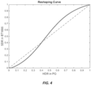
- FIG. 4 An example of such mapping between ST 2084 (PQ) and BT 1866 is shown in FIG. 4 .
- the curve has higher mid-tone contrast, lower blacks, and brighter (with less contrast) highlights. This aligns the tone scale more closely with standard SDR, so that when the input is decoded by a legacy device the image is still viewable.
- input and output values are normalized to (0, 1).
- Reshaping information may be signaled from an encoder to the rest of the pipeline as metadata.
- the reshaping parameters may be determined at a variety of time instances, such as on a per frame basis, on a per scene basis, or on a per sequence basis, to yield the best possible performance for a given video sequence.
- a Rec. 2020 bitstream may be adjusted using signal reshaping techniques as described herein to provide better hue and saturation output when decoded using a legacy Rec. 709 decoder.
- FIG. 6 depicts an example process flow for generating a color-rotation and scaling matrix according to an embodiment.
- step (610) computes hue and saturation values for the images in the database in a first (legacy) color space (e.g. YCbCr-gamma).
- step (615) computes hue for the images in the database in a second (preferred) color space (e.g. IPT-PQ).
- step (620) solves for an optimum rotation angle a' according to a minimization cost criterion (such as mean square error (MSE)) which minimizes the distance between hues computed in the legacy color space and hues computed in a rotated preferred color space.
- a minimization cost criterion such as mean square error (MSE)
- MSE mean square error
- An optional saturation scaler may also be computed. Given a saturation cost function (e.g., equation 8), step (630), optionally, solves for an optimum scaler b ' according to a minimization cost criterion, such as the MSE between the saturation of signals in the first color space and the saturation of scaled signals in a color-rotated preferred color space (640, 645).
- a saturation cost function e.g., equation 8
- step (630) optionally, solves for an optimum scaler b ' according to a minimization cost criterion, such as the MSE between the saturation of signals in the first color space and the saturation of scaled signals in a color-rotated preferred color space (640, 645).
- step (635) the rotation angle and the scaler are combined to generate a color-rotation and scaling matrix (e.g., equation (11)).
- the encoder will apply the color-rotation and scaling matrix to the input data in the preferred color space to generate data in a reshaped color space.
- Data will be encoded (compressed) and transmitted to a decoder together with information related to the color-rotation and scaling matrix.
- a legacy decoder will decode the data assuming it is coded in the legacy color space. Despite using the wrong color space information, images will still be viewable at adequate quality, albite in a lower dynamic range.
- a newer, fully-enabled, decoder may take advantage of the received metadata information on the color-rotation and scaling matrix to decode the image data in the preferred color space, thus providing to a viewer the full high-dynamic range of the data.
- the rotation (R) matrix and scaling vector ( S ) may be absorbed by the L'M'S' to I'P'T' conversion matrix in (230).
- the tone reshaping curve may be part of the forward color reshaping (305).
- the adaptive reshaping information (that is, the matrix and the tone-mapping curve) may be transmitted by the encoder to the decoder using the syntax proposed in U.S. Provisional Application Ser. No. 62/193,390, filed on July 16, 2015 , also filed as PCT Application with Ser. No. PCT/US2016/02861 on April 19, 2016 , which is incorporated herein by reference in its entirety.
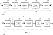
- a new color rotation and scale block (510) may be added in an encoder (500A). This block may be added after the color transformation (200) (e.g., RGB to IPT-PQ) but preferably before the forward reshaping (305).
- a decoder (500B) a corresponding inverse color rotation and scaling block (515) may be added after the backward reshaping box (320).
- optional color format conversion boxes e.g., 4:4:4 to 4:2:0 (505) or 4:2:0 to 4:4:4 (520) may be added in the encoding and/or decoding pipeline as needed.
- Table 1 provides an example of SEI messaging to communicate a color rotation and scaling matrix; however, signaling is not limited in SEI message; it can be inserted in any high level syntax, like SPS, PPS, etc.
- colour_rotation_scale_matrix_present_flag 1 indicates that the syntax elements colour_rotation_scale_coeffs [ c ][ i ], for c and i in the range of 0 to 1, inclusive, are present.
- colour_rotation_scale_matrix_present_flag 0 indicates that the syntax elements colour_rotation_scale_coeffs [ c ][ i ], for c and i in the range of 0 to 1, inclusive, are not present.
- colour_rotation_scale_coeffs [ c ][ i ] specifies the value of the two-by-two colour rotation and scale matrix coefficients.
- the value of colour_rotation_scale_coeffs [ c ][ i ] shall be in the range of -2 ⁇ 15 to 2 ⁇ 15 - 1, inclusive.
- colour_rotation_scale_coeffs [ c ][ i ] is not present, the default colour rotation and scale matrix matrix is used.
- both the encoder and the decoder may be aware of the color-rotation and scaling matrix (e.g., through the mutual definition of a new color space), hence it may not be needed to signal the color-rotation matrix from an encoder to the decoder.
- the color-rotation and scaling matrix can be referenced in VUI (Video Usability Information) together with IPT-PQ.
- N hues e.g., skin tones, sky, greens, and the like.
- a set of optimal (rotation angle, saturation scale) values e.g., ⁇ ( a 1 , bi), ( a 2 , b 2 ),..., ( a N , b N ) ⁇ .
- pixel p a p f H h p
- Functions f H ( h ( p )) and f S ( h ( p )) may be represented and stored in a variety of ways known in the art, for example, as look-up tables or piece-wise linear or non-linear polynomials, and can be signaled from an encoder to a decoder as metadata.
- the encoder may signal to the decoder the inverse of the f S ( h ( p )) (e.g., 1/ b ( p ) values).
- trigonometric operations may be performed using look-up tables.
- T p s p sin h ′ p ⁇ a p .
- FIG. 7A depicts an example backward reshaping function to convert hue from reshaped IPT-PQ-r (which appears as YCbCr to a legacy device) back to IPT-PQ when the legacy color space is YCbCr-gamma.
- FIG. 7B depicts the corresponding backward reshaping function to adjust the saturation.
- FIG. 8 depicts how the preferred color space IPT-PQ (820) may be adjusted to match the characteristics of the legacy YCbCr color space (810).
- Rays (830) depict the rotation and scaling.
- the v () and w () functions, as before, can been communicated from the encoder to the decoder using metadata or they can be part of an established coding protocol or standard known by both the encoder and the decoder.
- IC T C P also to be referred to as ICtCp (or IPT)
- IPT ITP-PQ
- I Intensity
- C T Tritan Axis
- C P Protan Axis
- the term "isoluminance” refers to a measure of how well luminance (say, I of ICtCp or Y' of Y'Cb'Cr') correspond to luminance Y . Indirectly, it measures how well a color space separates luma from chroma. Experiments performed by the inventors indicate that I of ICtCp corresponds much closer to luma than Y' of Y'Cb'Cr'.
- the EOTF ST 2084 ⁇ 1 function may be replaced by another non-linear quantization function such as the Hybrid Log-Gamma (HLG) function.
- HLG Hybrid Log-Gamma
- the corresponding L'M'S' to RGB and IC T C P to L'M'S' matrices are given by:
- R G B 3.436606694333078 ⁇ 2.5064521118656270 0.069845424323191 ⁇ 0.791329555598929 1.983600451792291 ⁇ 0.192270896193362 ⁇ 0.025949899690593 ⁇ 0.098913714711726 1.12486314402319
- L ′ M ′ S ′ L ′ M ′ S ′ 1.0 0.008609037037933 0.1110296250030260 1.0 ⁇ 0.008609037037933 ⁇ 0.111029625003026 1.0 0.560031335710679 ⁇ 0.320627174987319 I C T C P
- High dynamic range content may be viewed on displays that have less dynamic range than the reference display used to master the content.
- display mapping should be performed. This can take the form of an EETF (electrical-electrical transfer function) in the display, which is typically applied before applying the EOTF for the display. This function provides a toe and shoulder to gracefully roll off the highlights and shadows providing a balance between preserving the artistic intent and maintaining details.
- FIG. 9 is an example EETF mapping from the full 0-10,000 nits dynamic range to a target display capable of 0. 1-1,000 nits.
- the EETF may be introduced into the PQ signal; the plots show the effect of the mapping, i.e. they illustrate how the intended light is changed into the actual displayed light.
- the EETF may be applied in the non-linear domain to either the luma channel in IC T C P or Y'C' B C' R or to RGB channels individually.
- the central region of the tone mapping curve is defined as a one-to-one mapping from source to target.
- An additional toe and shoulder roll off are calculated using a Hermite spline to reduce the dynamic range to the capabilities of the target display.
- the turning points (Toe Start (TS) and Shoulder Start (SS)) for the spline are defined first. These are the points where the roll offs begin.
- the output E 2 is computed as follows.
- the resulting EETF curve can be applied to either the intensity I channel of IC T C P or the luma Y channel of Y'C' B C' R .
- I channel of IC T C P or the luma Y channel of Y'C' B C' R .
- Embodiments of the present invention may be implemented with a computer system, systems configured in electronic circuitry and components, an integrated circuit (IC) device such as a microcontroller, a field programmable gate array (FPGA), or another configurable or programmable logic device (PLD), a discrete time or digital signal processor (DSP), an application specific IC (ASIC), and/or apparatus that includes one or more of such systems, devices or components.
- IC integrated circuit
- FPGA field programmable gate array
- PLD configurable or programmable logic device
- DSP discrete time or digital signal processor
- ASIC application specific IC
- the computer and/or IC may perform, control, or execute instructions relating to signal reshaping and coding of images with enhanced dynamic range, such as those described herein.
- the computer and/or IC may compute any of a variety of parameters or values that relate to the signal reshaping and coding processes described herein.
- the image and video embodiments may be implemented in hardware, software, firmware and various combinations
- Certain implementations of the invention comprise computer processors which execute software instructions which cause the processors to perform a method of the invention.
- processors in a display, an encoder, a set top box, a transcoder or the like may implement methods related to signal reshaping and coding of HDR images as described above by executing software instructions in a program memory accessible to the processors.
- the invention may also be provided in the form of a program product.
- the program product may comprise any non-transitory medium which carries a set of computer-readable signals comprising instructions which, when executed by a data processor, cause the data processor to execute a method of the invention.
- Program products according to the invention may be in any of a wide variety of forms.
- the program product may comprise, for example, physical media such as magnetic data storage media including floppy diskettes, hard disk drives, optical data storage media including CD ROMs, DVDs, electronic data storage media including ROMs, flash RAM, or the like.
- the computer-readable signals on the program product may optionally be compressed or encrypted.
- a component e.g. a software module, processor, assembly, device, circuit, etc.
- reference to that component should be interpreted as including as equivalents of that component any component which performs the function of the described component (e.g., that is functionally equivalent), including components which are not structurally equivalent to the disclosed structure which performs the function in the illustrated example embodiments of the invention.
Landscapes
- Engineering & Computer Science (AREA)
- Multimedia (AREA)
- Signal Processing (AREA)
- Physics & Mathematics (AREA)
- Computer Hardware Design (AREA)
- General Physics & Mathematics (AREA)
- Theoretical Computer Science (AREA)
- Image Processing (AREA)
- Processing Of Color Television Signals (AREA)
- Compression Or Coding Systems Of Tv Signals (AREA)
- Facsimile Image Signal Circuits (AREA)
- Color Image Communication Systems (AREA)
Abstract
Description
- This application is a European divisional application of Euro-PCT patent application
EP 16757757.6 (reference: D15076AEP01), filed 3 August 2016 - The present invention relates generally to images. More particularly, an embodiment of the present invention relates to signal reshaping of images with high dynamic range to improve backwards compatibility
- As used herein, the term 'dynamic range' (DR) may relate to a capability of the human visual system (HVS) to perceive a range of intensity (e.g., luminance, luma) in an image, e.g., from darkest darks (blacks) to brightest whites (i.e., highlights). In this sense, DR relates to a 'scene-referred' intensity. DR may also relate to the ability of a display device to adequately or approximately render an intensity range of a particular breadth. In this sense, DR relates to a 'display-referred' intensity. Unless a particular sense is explicitly specified to have particular significance at any point in the description herein, it should be inferred that the term may be used in either sense, e.g. interchangeably.
- As used herein, the term high dynamic range (HDR) relates to a DR breadth that spans the some 14-15 orders of magnitude of the human visual system (HVS). In practice, the DR over which a human may simultaneously perceive an extensive breadth in intensity range may be somewhat truncated, in relation to HDR. As used herein, the terms enhanced dynamic range (EDR) or visual dynamic range (VDR) may individually or interchangeably relate to the DR that is perceivable within a scene or image by a human visual system (HVS) that includes eye movements, allowing for some light adaptation changes across the scene or image. As used herein, EDR may relate to a DR that spans 5 to 6 orders of magnitude. Thus while perhaps somewhat narrower in relation to true scene referred HDR, EDR nonetheless represents a wide DR breadth and may also be referred to as HDR.
- In practice, images comprise one or more color components (e.g., luma Y and chroma Cb and Cr) wherein each color component is represented by a precision of n-bits per pixel (e.g., n=8). Using linear luminance coding, images where n ≤ 8 (e.g., color 24-bit JPEG images) are considered images of standard dynamic range, while images where n > 8 may be considered images of enhanced dynamic range. EDR and HDR images may also be stored and distributed using high-precision (e.g., 16-bit) floating-point formats, such as the OpenEXR file format developed by Industrial Light and Magic.
- Given a video stream, information about its coding parameters is typically embedded in the bit stream as metadata. As used herein, the term "metadata" relates to any auxiliary information that is transmitted as part of the coded bitstream and assists a decoder to render a decoded image. Such metadata may include, but are not limited to, color space or gamut information, reference display parameters, and auxiliary signal parameters, as those described herein.
- Most consumer desktop displays currently support luminance of 200 to 300 cd/m2 or nits. Most consumer HDTVs range from 300 to 500 nits with new models reaching 1000 nits (cd/m2). Such conventional displays thus typify a lower dynamic range (LDR), also referred to as a standard dynamic range (SDR), in relation to HDR or EDR. As the availability of HDR content grows due to advances in both capture equipment (e.g., cameras) and HDR displays (e.g., the PRM-4200 professional reference monitor from Dolby Laboratories), HDR content may be color graded and displayed on HDR displays that support higher dynamic ranges (e.g., from 1,000 nits to 5,000 nits or more). In general, without limitation, the methods of the present disclosure relate to any dynamic range higher than SDR. As appreciated by the inventors here, improved techniques for the coding of high-dynamic range images are desired.
- The approaches described in this section are approaches that could be pursued, but not necessarily approaches that have been previously conceived or pursued. Therefore, unless otherwise indicated, it should not be assumed that any of the approaches described in this section qualify as prior art merely by virtue of their inclusion in this section. Similarly, issues identified with respect to one or more approaches should not assume to have been recognized in any prior art on the basis of this section, unless otherwise indicated.
- An embodiment of the present invention is illustrated by way of example, and not in way by limitation, in the figures of the accompanying drawings and in which like reference numerals refer to similar elements and in which:
-
FIG. 1 depicts an example process for a video delivery pipeline; -
FIG. 2 depicts an example process for color conversion to the IPT-PQ color space; -
FIG. 3 depicts an example process for signal reshaping and coding; -
FIG. 4 depicts an example tone-mapping curve for luminance reshaping between ST 2084 IPT and BT 1866 IPT according to an embodiment of this invention; -
FIG. 5 depicts an example system for backward-compatible coding and decoding using color space reshaping according to an embodiment of this invention; -
FIG. 6 depicts an example process flow for generating a color-rotation and scaling matrix according to an embodiment of this invention; -
FIG. 7A and FIG. 7B depict hue and saturation reshaping functions according to an embodiment of this invention; -
FIG. 8 depicts an example of hue and saturation reshaping between the IPT-PQ and YCbCr-gamma color spaces according to an embodiment of this invention; and -
FIG. 9 depicts an example of an EETF function according to an embodiment of this invention. - Signal reshaping and coding of high dynamic range (HDR) images is described herein. In the following description, for the purposes of explanation, numerous specific details are set forth in order to provide a thorough understanding of the present invention. It will be apparent, however, that the present invention may be practiced without these specific details. In other instances, well-known structures and devices are not described in exhaustive detail, in order to avoid unnecessarily occluding, obscuring, or obfuscating the present invention.
- Example embodiments described herein relate to the reshaping and coding of high-dynamic range images. In a method to improve backward compatible decoding, in an encoder, a processor accesses an image database and
- computes first hue values of the images in the database in a first color space;
- computes second hue values of the images in the database in a second color space;
- computes a hue rotation angle based on minimizing a hue cost function, wherein the hue cost function is based on a difference measure of the first hue values and rotated second hue values; and
- generates a color-rotation matrix based on the hue rotation angle.
- In an embodiment, the first color space is a gamma-based YCbCr color space and the second color space is a PQ-based IPT color space.
- In an embodiment, the color-rotation matrix is used to generate a reshaped color space based on the preferred color space. Images are coded using the reshaped color space, and information about the color rotation matrix is signaled from the encoder to a decoder.
- In an embodiment, in a decoder, in a method to reconstruct an input image coded in a reshaped color space, the decoder:
- receives a coded input image in a reshaped color space, wherein the reshaped color space is generated by rotating chroma components of a preferred color space to approximate one or more parameters of a legacy color space;
- accesses metadata transmitted from an encoder to the decoder, wherein the metadata is associated with the coded input image and comprise:
- a flag indicating the presence or not of a color-rotation and scaling matrix; and
- a plurality of coefficients for the color-rotation and scaling matrix when the flag indicates the presence of the color-rotation and scaling matrix;
- decodes the coded input image to generate a decoded image in the reshaped color space; and
- generates a decoded image in the preferred color space based on the decoded image in the reshaped color space and the color-rotation and scaling matrix.
- In another embodiment, in an encoder, a processor:
- receives an input image in a preferred color space;
- accesses a hue rotation function, wherein for a hue value of a pixel in the input image in the preferred color space, the hue rotation function generates a rotated hue output value that matches according to a hue-cost criterion a hue value in a legacy color space;
- generates a reshaped image based on the input image and the hue rotation function; and
- encodes the reshaped image to generate a coded reshaped image.
- In another embodiment, in a decoder, a processor:
- accesses an input image encoded in a reshaped color space;
- accesses metadata associated with the input image, wherein the metadata comprise data associated with a hue rotation function used to translate the input image from a preferred color space to the reshaped color space, wherein for a hue value of a pixel in the input image in the preferred color space, the hue rotation function generates a rotated hue output value that matches according to a hue-cost criterion a hue value in a legacy color space; and
- generates an output image in the preferred color space based on the input image and the data associated with the hue rotation function.
-
FIG. 1 depicts an example process of a conventional video delivery pipeline (100) showing various stages from video capture to video content display. A sequence of video frames (102) is captured or generated using image generation block (105). Video frames (102) may be digitally captured (e.g. by a digital camera) or generated by a computer (e.g. using computer animation) to provide video data (107). Alternatively, video frames (102) may be captured on film by a film camera. The film is converted to a digital format to provide video data (107). In a production phase (110), video data (107) is edited to provide a video production stream (112). - The video data of production stream (112) is then provided to a processor at block (115) for post-production editing. Post-production editing (115) may include adjusting or modifying colors or brightness in particular areas of an image to enhance the image quality or achieve a particular appearance for the image in accordance with the video creator's creative intent. This is sometimes called "color timing" or "color grading." Other editing (e.g. scene selection and sequencing, image cropping, addition of computer-generated visual special effects, etc.) may be performed at block (115) to yield a final version (117) of the production for distribution. During post-production editing (115), video images are viewed on a reference display (125).
- Following post-production (115), video data of final production (117) may be delivered to encoding block (120) for delivering downstream to decoding and playback devices such as television sets, set-top boxes, movie theaters, and the like. In some embodiments, coding block (120) may include audio and video encoders, such as those defined by ATSC, DVB, DVD, Blu-Ray, and other delivery formats, to generate coded bit stream (122). In a receiver, the coded bit stream (122) is decoded by decoding unit (130) to generate a decoded signal (132) representing an identical or close approximation of signal (117). The receiver may be attached to a target display (140) which may have completely different characteristics than the reference display (125). In that case, a display management block (135) may be used to map the dynamic range of decoded signal (132) to the characteristics of the target display (140) by generating display-mapped signal (137).
- In a preferred embodiment, without limitation, part of the processing pipeline, for example, coding (120), decoding (130), and display management (135) may be performed in what will be referred to as the IPT-PQ color space. An example use of the IPT-PQ color space for display management application can be found in "Display Management for High Dynamic Range Video," WIPO Publication
WO 2014/130343, by R. Atkins et al. , which is incorporated by reference in its entirety. The IPT color space, as described in " Development and testing of a color space (ipt) with improved hue uniformity", by F. Ebner and M.D. Fairchild, in Proc. 6th Color Imaging Conference: Color Science, Systems, and Applications, IS&T, Scottsdale, Arizona, Nov. 1998, pp. 8-13 (to be referred to as the Ebner paper), which is incorporated herein by reference in its entirety, is a model of the color difference between cones in the human visual system. In this sense it is like the YCbCr or CIE-Lab color spaces; however, it has been shown in some scientific studies to better mimic human visual processing than these spaces. Like CIE-Lab, IPT is a normalized space to some reference luminance. In an embodiment, the normalization is based on the maximum luminance of a target display (e.g., 5,000 nits). - The term "PQ" as used herein refers to perceptual quantization. The human visual system responds to increasing light levels in a very non-linear way. A human's ability to see a stimulus is affected by the luminance of that stimulus, the size of the stimulus, the spatial frequency(ies) making up the stimulus, and the luminance level that the eyes have adapted to at the particular moment one is viewing the stimulus. In a preferred embodiment, a perceptual quantizer function maps linear input gray levels to output gray levels that better match the contrast sensitivity thresholds in the human visual system. Examples of PQ mapping functions are described in
U.S. Patent Ser. No. 9,077,994 (to be referred as the `994 Patent)," by J. S. Miller et al. -
FIG. 2 depicts in more detail an example process (200) for the color conversion into the IPT-PQ color space according to an embodiment. As depicted inFIG. 2 , given input signal (202) which is in a first color space (e.g., RGB), the color space transformation in the perceptually-corrected IPT color space (IPT-PQ) may comprise the following steps: - a) Optional step (210) may normalize the pixel values of the input signal (202) (e.g., 0 to 4095) into pixel values with a dynamic range between 0 and 1.
- b) If the input signal (202) is gamma-coded or PQ-coded (e.g., per BT. 1866 or SMPTE ST 2084), optional step (215) may use the signal's electro-optical transfer function (EOTF) (as provided by signal metadata) to reverse or undo the source display's conversion from code values to luminance. For example, if the input signal is gamma coded, then this step applies an inverse gamma function. If the input signal is PQ-encoded according to SMPTE ST 2084, then this step applies an inverse PQ function. In practice, the normalization step (210) and the inverse non-linear encoding (215) may be performed using pre-computed 1-D Look-up tables (LUTs) to generate a
linear signal 217. - c) In step (220),
linear signal 217 is converted from its original color space (e.g., RGB, XYZ, and the like) into the LMS color space. For example, if the original signal is in RGB, then this step may comprise two steps: an RGB to XYZ color transformation and an XYZ to LMS color transformation. In an embodiment, without limitation, the XYZ to LMS transformation may be given by
In an another embodiment, as described inUnited States Provisional Patent Application Ser. No. 62/056,093, filed on Sept. 26, 2014 PCT/US2015/051964, on Sept. 24, 2015 ) which is incorporated herein by reference in its entirety, the overall coding efficiency in the IPT-PQ color space may be further increased if one incorporates a cross-talk matrix 


- d) According to the Ebner paper, the traditional LMS to IPT color space conversion comprises applying first a non-linear power function to the LMS data and then applying a linear transformation matrix. While one can transform the data from LMS to IPT and then apply the PQ function to be in the IPT-PQ domain, in a preferred embodiment, in step (225) the traditional power function for a non-linear encoding of LMS to IPT is replaced with the PQ non-linear encoding of each one of the L,M, and S components.
- e) Using an LMS to IPT linear transform (e.g., as defined in the Ebner paper), step (230) completes the conversion of
signal 222 to the IPT-PQ color space. For example, in an embodiment, the L'M'S' to IPT-PQ transform may be given by

- Most of the existing video compression standards, such as MPEG-1, MPEG-2, AVC, HEVC, and the like, have been tested, evaluated, and optimized for gamma-coded images in the YCbCr color space; however, experimental results have shown that the IPT-PQ color space may provide a better representation format for high-dynamic range images with 10 or more bits per pixel per color component. Signal encoding in color spaces that are better suited for HDR and wide color gamut signals (e.g., IPT-PQ) may yield better overall picture quality; however, legacy decoders (e.g., set-top boxes and the like) may be unable to do proper decoding and color conversion. To improve backwards compatibility, so that even devices that are not aware of the new color spaces can generate a reasonable picture, as appreciated by the inventors, new signal reshaping techniques are needed.
-
FIG. 3 depicts an example process for signal reshaping and coding according to an embodiment. As depicted inFIG. 3 , given input (302), the forward color reshaping block (305) applies, as needed, color transformation and or reshaping functions to generate a signal (307) in a preferred color space (e.g., IPT-PQ-r). Reshaping-related metadata (309) may also be generated and communicated to subsequent blocks of the coding pipeline, such as the encoder (310), the decoder (315), and backward color reshaping (320). - A decoder, after receiving coded signal (315) will apply decoding (315) (such as HEVC decoding) to generate decoded signal (317). A decoder aware of the preferred HDR-WCG coding color space (e.g., IPT-PQ-r), will apply a proper backward or reverse reshaping (320) to generate a signal (322) in the proper color space (say, IPT-PQ). Then, signal (322) may be transformed to YCbCr or RGB for additional post-processing, storage, or display.
- A legacy decoder, which is not aware of the preferred HDR-WCG coding space, may treat the HDR-WCG space as a legacy color space (e.g., gamma-coded YCbCr); however, due to the forward color reshaping (305), output (317) may still have a reasonable picture quality, despite the fact that no backward reshaping or other color transformation is applied to output (317) of the decoder.
- Consider, without loss of generality, the IPT-PQ color space. In an embodiment, a linear reshaping matrix (e.g., a 3 x 3 matrix) is generated to perceptually match the skin tones in an IPT-PQ signal with the skin-tones in a YCbCr-gamma signal. Such a color transformation has no effect on the performance of most image processing applications in the IPT color space, yet greatly improves color reproduction by a legacy device. Instead of or in addition of skin tones, similar transformation matrices may also be generated to match other important colors, such as foliage, sky, etc. In an embodiment, the reshaping matrix may be computed as follows:
- a) Load a database of skin-tone colors, for example, reflectance spectrums, and convert them to a device independent color space, such as XYZ;
- b) Convert the database of skin tones from XYZ into the legacy color space format (e.g., YCbCr, Rec. 709). This step may include, for example, the following substeps:
- b. 1) Convert the database to RGB (Rec. 709);
- b.2) Apply a gamma to the RGB values (e.g., per BT. 1886) to generate a gamma-coded R'G'B' signal;
- b.3) Convert the R'G'B' signals to YCbCr-gamma values (e.g., per Rec. 709);
- b.4) Compute Hue (e.g.,

- b.5) Compute saturation values (e.g.,

- c) Compute the skin tone values in the database in the preferred color format (e.g. IPT-PQ). This step may include the following sub-steps:
- c.1) Convert XYZ to LMS;
- c.2) Convert LMS to L'M'S' and to I'P'T' by applying PQ (e.g., per ST 2084);
- c.3) Compute Hue values (e.g.,

- c.4) Compute Saturation values

- d) Compute a rotation matrix to rotate the IPT values so that skin tones in a rotated or reshaped IPT-PQ (e.g., IPT-PQ-r) are aligned with skin tones in YCbCr-gamma. In an embodiment, this step is computed by optimizing a cost function related to the hue and saturation values of the samples in the two color spaces. For example, in an embodiment the cost function may represent the mean square error (MSE) between the legacy color space (e.g., YCbCr) and the rotated preferred HDR color space (e.g., IPT-PQ). For example, Let


- In an embodiment, one may apply any known in the art optimization techniques to find the value of angle "a", to be denoted as a', to minimize the cost function according to a given criterion. For example, one may apply the MATLAB function fminunc(fun, x0), with fun = CostH and x0 = 0.1. Given a', the rotation matrix R may be defined as

- As an example, based on a sample database, in an embodiment, for a' = 71.74 degrees

- Given R and the original L 'M'S' to I'P'T' matrix LMS2IPTmat (see for example, equation (2)), the conversion to the reshaped IPT-PQ-r color space may use a new LMS2IPTmat-r matrix defined as:

- In an embodiment, in addition to aligning the hues for the skin tones, one may also align the saturation. This may include the following steps:
- a) Apply R to the original IPT-PQ data to generate color-rotated chroma values PR and TR data
- b) Define a saturation cost function, e.g., the MSE between saturation values in the original and target color spaces:


- c) Let b' denote the b value that optimizes Costs. Then, one can apply a scaling vector


- In some embodiment, the hue-cost and saturation-cost functions (e.g., equations (3) and (8) may be combined into a single hue/saturation cost function and solved for both a' and b' simultaneously. For example, from equation (11), in an embodiment, for


- For example, in an embodiment, for a' = 65 degrees and b1' = 1.4, b2' = 1.0, b3 ' = 1.4, and b4' = 1.0 , equation (12) yields:

- The proposed rotation matrix R may improve the color reproduction; however, the decoded image (317) may still be perceived to have low contrast due to the difference in the non-linear EOTF encoding functions (e.g., ST 2084 versus BT 1866). In an embodiment, the contrast may be improved by applying a 1-D tone-mapping curve to the luminance channel (e.g., I'). This step may include the following sub-steps:
- a) Apply a tone-mapping curve (e.g., a sigmoid) to map the original content from an original HDR maximum brightness (e.g., 4,000 nits) to an SDR target brightness (e.g., 100 nits). An example of such a sigmoid function may be found in
U.S. Patent 8,593,480, "Method and Apparatus for Image Data Transformation," by A. Ballestad and A. Kostin , which is incorporated herein by reference in its entirety. Examples of alternative reshaping functions were also disclosed in WIPO PublicationWO 2014/160705 , "Encoding perceptually-quantized video content in multi-layer VDR coding," which is incorporated herein by reference in its entirety. Let
- b) Linearize

- c) Apply legacy EOTF encoding (e.g., BT. 1866) encoding to the linearized IT signal to generate a gamma-coded luminance signal to be compressed and transmitted by the encoder.
- An example of such mapping between ST 2084 (PQ) and BT 1866 is shown in
FIG. 4 . The curve has higher mid-tone contrast, lower blacks, and brighter (with less contrast) highlights. This aligns the tone scale more closely with standard SDR, so that when the input is decoded by a legacy device the image is still viewable. InFIG. 4 , without loss of generality, input and output values are normalized to (0, 1). - Reshaping information may be signaled from an encoder to the rest of the pipeline as metadata. The reshaping parameters may be determined at a variety of time instances, such as on a per frame basis, on a per scene basis, or on a per sequence basis, to yield the best possible performance for a given video sequence.
- Although this description focuses on the IPT-PQ color space, these techniques are equally applicable to other color spaces and color formats. For example, similar techniques may be applied to improve backward compatibility across different versions of YCbCr, for example, Rec. 709 YCbCr and Rec. 2020 YCbCr. Thus, in an embodiment, a Rec. 2020 bitstream may be adjusted using signal reshaping techniques as described herein to provide better hue and saturation output when decoded using a legacy Rec. 709 decoder.
-
FIG. 6 depicts an example process flow for generating a color-rotation and scaling matrix according to an embodiment. Given an image database (605), step (610) computes hue and saturation values for the images in the database in a first (legacy) color space (e.g. YCbCr-gamma). Step (615) computes hue for the images in the database in a second (preferred) color space (e.g. IPT-PQ). - Given a hue-related cost function (e.g., equation (3)), step (620) solves for an optimum rotation angle a' according to a minimization cost criterion (such as mean square error (MSE)) which minimizes the distance between hues computed in the legacy color space and hues computed in a rotated preferred color space. In step (625) the value of a' is used to generate the color rotation matrix.
- An optional saturation scaler may also be computed. Given a saturation cost function (e.g., equation 8), step (630), optionally, solves for an optimum scaler b' according to a minimization cost criterion, such as the MSE between the saturation of signals in the first color space and the saturation of scaled signals in a color-rotated preferred color space (640, 645).
- Finally, in step (635), the rotation angle and the scaler are combined to generate a color-rotation and scaling matrix (e.g., equation (11)).
- In an encoder, the encoder will apply the color-rotation and scaling matrix to the input data in the preferred color space to generate data in a reshaped color space. Data will be encoded (compressed) and transmitted to a decoder together with information related to the color-rotation and scaling matrix.
- In a decoder, a legacy decoder will decode the data assuming it is coded in the legacy color space. Despite using the wrong color space information, images will still be viewable at adequate quality, albite in a lower dynamic range. A newer, fully-enabled, decoder may take advantage of the received metadata information on the color-rotation and scaling matrix to decode the image data in the preferred color space, thus providing to a viewer the full high-dynamic range of the data.
- As discussed earlier, in one embodiment, the rotation (R) matrix and scaling vector (S) may be absorbed by the L'M'S' to I'P'T' conversion matrix in (230). The tone reshaping curve may be part of the forward color reshaping (305). In both cases, the adaptive reshaping information (that is, the matrix and the tone-mapping curve) may be transmitted by the encoder to the decoder using the syntax proposed in
U.S. Provisional Application Ser. No. 62/193,390, filed on July 16, 2015 PCT/US2016/02861 on April 19, 2016 , which is incorporated herein by reference in its entirety. - In another embodiment, as depicted in
FIG. 5 , a new color rotation and scale block (510) may be added in an encoder (500A). This block may be added after the color transformation (200) (e.g., RGB to IPT-PQ) but preferably before the forward reshaping (305). In a decoder (500B), a corresponding inverse color rotation and scaling block (515) may be added after the backward reshaping box (320). As depicted inFIG. 5 , optional color format conversion boxes (e.g., 4:4:4 to 4:2:0 (505) or 4:2:0 to 4:4:4 (520)) may be added in the encoding and/or decoding pipeline as needed. - In terms of syntax, one may specify either a 3 x 3 rotation matrix or just a 2 x 2 matrix, since typically the luminance channel (e.g., Y or I) are left unchanged. Table 1 provides an example of SEI messaging to communicate a color rotation and scaling matrix; however, signaling is not limited in SEI message; it can be inserted in any high level syntax, like SPS, PPS, etc.
Table 1: Example SEI Messaging for color rotation and scaling matrix Colour_Rotation_Scale_Table( ) { Descriptor colour_rotation_scale_matrix_present_flag u(1) if( colour_rotation_scale_matrix_present_flag ) { for( c = 0; c < 2; c++ ) for( i = 0; i < 2; i++ ) colour_rotation_scale_coeffs[ c ] [ i ] i(16) } } - colour_rotation_scale_matrix_present_flag equal to 1 indicates that the syntax elements colour_rotation_scale_coeffs [ c ][ i ], for c and i in the range of 0 to 1, inclusive, are present. colour_rotation_scale_matrix_present_flag equal to 0 indicates that the syntax elements colour_rotation_scale_coeffs [ c ][ i ], for c and i in the range of 0 to 1, inclusive, are not present.
- colour_rotation_scale_coeffs [ c ][ i ] specifies the value of the two-by-two colour rotation and scale matrix coefficients. The value of colour_rotation_scale_coeffs [ c ][ i ] shall be in the range of -2^15 to 2^15 - 1, inclusive. When colour_rotation_scale_coeffs [ c ][ i ] is not present, the default colour rotation and scale matrix matrix is used.
- In an embodiment, both the encoder and the decoder may be aware of the color-rotation and scaling matrix (e.g., through the mutual definition of a new color space), hence it may not be needed to signal the color-rotation matrix from an encoder to the decoder. In another embodiment, the color-rotation and scaling matrix can be referenced in VUI (Video Usability Information) together with IPT-PQ.
- In some embodiments, it may be beneficial to apply the reshaping on multiple hues. This will increase the accuracy of the reshaped color space to match the legacy colors, but at the expense of additional computations at the decoder. Consider for example the problem of optimizing the reshaping for N hues (e.g., skin tones, sky, greens, and the like). In an embodiment, one may repeat the processes discussed earlier to identify a set of optimal angles and saturations as a function of hue. For example, using database images for a variety of hues one may generate a set of optimal (rotation angle, saturation scale) values, e.g., {(a1, bi), (a2, b2 ),..., (aN, bN )}. Or more generally, let for pixel p


- Functions fH (h(p)) and fS (h(p)) may be represented and stored in a variety of ways known in the art, for example, as look-up tables or piece-wise linear or non-linear polynomials, and can be signaled from an encoder to a decoder as metadata.
- Given fH (h(p)) and fS (h(p)), the encoder applies the following reshaping functions to each pixel:




- In a decoder, the process is reversed. For example, given fH (h(p)) and fS (h(p)), from equations (14) and (16), the decoder generates


- Note that to avoid a division in the decoder, in some embodiments the encoder may signal to the decoder the inverse of the fS (h(p)) (e.g., 1/ b(p) values). For input data in the IPT-PQ space, the original data may be generated as


- From equation (17), applying inverse reshaping to recover the data in the preferred color space requires trigonometric operations. In some embodiments, trigonometric operations may be performed using look-up tables. As an example, from equation (18), equation (19) may be rewritten as


-
FIG. 7A depicts an example backward reshaping function to convert hue from reshaped IPT-PQ-r (which appears as YCbCr to a legacy device) back to IPT-PQ when the legacy color space is YCbCr-gamma.FIG. 7B depicts the corresponding backward reshaping function to adjust the saturation.FIG. 8 depicts how the preferred color space IPT-PQ (820) may be adjusted to match the characteristics of the legacy YCbCr color space (810). Rays (830) depict the rotation and scaling. - In another embodiment, instead of computing P and T values in terms of cosine or sine functions of hue, one could construct a simpler decoder with look-up tables generated based on some other function of hue (e.g., f(tan -1(h(p)))). For example, given reshaped pixel value components P'r (p) and T'r (p), in an embodiment, the decoder may recover the original pixel values as follows:




- ICTCP, also to be referred to as ICtCp (or IPT), is a proposed new color space especially designed for processing high dynamic range and wide color gamut (WCG) signals. As with ITP-PQ, I (Intensity) denotes the brightness of the PQ-encoded signal, C T, Tritan Axis, corresponds to blue-yellow perception, and C P, Protan Axis, corresponds to red-green color perception. In addition to the discussed features of IPT-PQ, in ICTCP:
- As described earlier, chroma is rotated to align skin tones more closely to YCbCr
- The XYZ to LMS matrix is optimized for better uniformity and linearity for WCG images
- The L'M' S' to ICtCp matrix is optimized to improve isoluminance and stability with respect to HDR and WCG images
- As used herein, the term "isoluminance" refers to a measure of how well luminance (say, I of ICtCp or Y' of Y'Cb'Cr') correspond to luminance Y. Indirectly, it measures how well a color space separates luma from chroma. Experiments performed by the inventors indicate that I of ICtCp corresponds much closer to luma than Y' of Y'Cb'Cr'.
- From an implementation point of view, using the ICTCP color space requires the same hardware and signal flow as using the traditional gamma-coded YCbCr. For example, consider using gamma-corrected YCbCr (Y'Cb'Cr') in a camera pipeline. Starting from XYZ, the process requires the following steps:
- a) Converting from XYZ to RGB BT.2020 using a 3 x 3 matrix
- b) Applying an inverse EOTF (or OETF) to the output of step a); and
- c) Applying a 3 x 3 matrix to the output of step b)
- As depicted in
FIG. 2 , using the ICTCP color requires the following steps: - a) In step (220), converting from XYZ to LMS using, in a preferred embodiment, the following 3 x 3 matrix:

- b) In step (225) converting signal (222) to L'M'S', as described earlier, by applying the PQ non-linearity
- c) In step (230), converting from L'M'S' to ICTCP using a 3 x 3 matrix, which in a preferred embodiment may be defined as:

- In another embodiment, steps a) to c) can also be expressed as follows:





Table 2: Color Conversion to ICTCP Parameter Values PQ L, M, S Colour Space 


Derivation of L', M', S' {L', M', S'}=EOTF-1(FD ) where FD = {LD, MD, SD } Derivation of I' 
Derivation of colour difference signals 

- The conversion from ICTCP back to the original color space follows a similar approach, and in an embodiment it may include the following steps:
- a) Convert from ICTCP to L'M'S' using the inverse of equation (23) or

- b) Convert the L'M'S' signal to LMS using the signal's EOTF function (e.g., as defined in ST 2084; and
- c) Convert from LMS to XYZ using the inverse of equation (22), for example:

- In an embodiment, the corresponding L'M'S' to RGB and ICTCP to L'M'S' matrices are given by:


- High dynamic range content may be viewed on displays that have less dynamic range than the reference display used to master the content. In order to view HDR content on displays with a lower dynamic range, display mapping should be performed. This can take the form of an EETF (electrical-electrical transfer function) in the display, which is typically applied before applying the EOTF for the display. This function provides a toe and shoulder to gracefully roll off the highlights and shadows providing a balance between preserving the artistic intent and maintaining details.
FIG. 9 is an example EETF mapping from the full 0-10,000 nits dynamic range to a target display capable of 0. 1-1,000 nits. The EETF may be introduced into the PQ signal; the plots show the effect of the mapping, i.e. they illustrate how the intended light is changed into the actual displayed light. - Below are the mathematical steps that implement this tone mapping function for displays of various black and white luminance levels. The EETF may be applied in the non-linear domain to either the luma channel in ICTCP or Y'C'BC'R or to RGB channels individually.
- The central region of the tone mapping curve is defined as a one-to-one mapping from source to target. An additional toe and shoulder roll off are calculated using a Hermite spline to reduce the dynamic range to the capabilities of the target display.
- The turning points (Toe Start (TS) and Shoulder Start (SS)) for the spline are defined first. These are the points where the roll offs begin. Let minLum and maxLum denote the minimum and maximum luminance values of the target display, then:


- Given E1, the source input signal in normalized PQ code words, the output E2 is computed as follows.
- For 0 ≤ E 1 ≤ TS
- X 1 = 0
- Y 1 = minLum
- X 2, Y 2 = TS
- E 2 = P(E 1, X 1, Y 1, X 2, Y 2)
- For TS < E 1 < SS
E 2 = E 1 - For SS ≤ E 1 ≤ 1
- X 1, Y 1 = SS
- X 2 = 1
- Y 2 = maxLum
- E 2 = P(E 1 , X 1 , Y 1 , X 2, Y 2)
-


- In another embodiment:
- STEP 1:

SS 
- STEP 2:

-


- The resulting EETF curve can be applied to either the intensity I channel of ICTCP or the luma Y channel of Y'C'BC'R. Here are some notable options:
- 1) I of ICTCP - process the intensity (I) channel of ICTCP though the EETF

- Adjusts grayscale more accurately
- No color shifts
- Changes in saturation will be needed and should be applied to the CT and CP channels using this equation:

- 2) Y' of Y'C'BC' R - process the luma Y' channel of Y'C'BC' R though the EETF

- Adjusts grayscale more accurately
- Limited color shifts
- Changes in saturation will be needed and should be applied to the C'B and C'R channels using this equation:

- Embodiments of the present invention may be implemented with a computer system, systems configured in electronic circuitry and components, an integrated circuit (IC) device such as a microcontroller, a field programmable gate array (FPGA), or another configurable or programmable logic device (PLD), a discrete time or digital signal processor (DSP), an application specific IC (ASIC), and/or apparatus that includes one or more of such systems, devices or components. The computer and/or IC may perform, control, or execute instructions relating to signal reshaping and coding of images with enhanced dynamic range, such as those described herein. The computer and/or IC may compute any of a variety of parameters or values that relate to the signal reshaping and coding processes described herein. The image and video embodiments may be implemented in hardware, software, firmware and various combinations thereof.
- Certain implementations of the invention comprise computer processors which execute software instructions which cause the processors to perform a method of the invention. For example, one or more processors in a display, an encoder, a set top box, a transcoder or the like may implement methods related to signal reshaping and coding of HDR images as described above by executing software instructions in a program memory accessible to the processors. The invention may also be provided in the form of a program product. The program product may comprise any non-transitory medium which carries a set of computer-readable signals comprising instructions which, when executed by a data processor, cause the data processor to execute a method of the invention. Program products according to the invention may be in any of a wide variety of forms. The program product may comprise, for example, physical media such as magnetic data storage media including floppy diskettes, hard disk drives, optical data storage media including CD ROMs, DVDs, electronic data storage media including ROMs, flash RAM, or the like. The computer-readable signals on the program product may optionally be compressed or encrypted.
- Where a component (e.g. a software module, processor, assembly, device, circuit, etc.) is referred to above, unless otherwise indicated, reference to that component (including a reference to a "means") should be interpreted as including as equivalents of that component any component which performs the function of the described component (e.g., that is functionally equivalent), including components which are not structurally equivalent to the disclosed structure which performs the function in the illustrated example embodiments of the invention.
- Example embodiments that relate to the efficient signal reshaping and coding of HDR images are thus described. In the foregoing specification, embodiments of the present invention have been described with reference to numerous specific details that may vary from implementation to implementation. Thus, the sole and exclusive indicator of what is the invention, and is intended by the applicants to be the invention, is the set of claims that issue from this application, in the specific form in which such claims issue, including any subsequent correction. Any definitions expressly set forth herein for terms contained in such claims shall govern the meaning of such terms as used in the claims. Hence, no limitation, element, property, feature, advantage or attribute that is not expressly recited in a claim should limit the scope of such claim in any way. The specification and drawings are, accordingly, to be regarded in an illustrative rather than a restrictive sense.
- Various aspects of the present invention may be appreciated from the following Enumerated Example Embodiments (EEEs):
- 1. A method to improve backward compatible decoding, the method comprising:
- accessing with a processor an image database (605);
- computing (610) first hue values of the images in the database in a first color space;
- computing (615) second hue values of the images in the database in a second color space;
- computing (620) a hue rotation angle based on minimizing a hue cost function, wherein the hue cost function is based on a difference measure of the first hue values and rotated second hue values; and
- generating (625) a color-rotation matrix based on the hue rotation angle.
- 2. The method of
EEE 1, further comprising:- computing (610) first saturation values of the images in the database in the first color space;
- transforming the images in the database into the second color space to generate transformed images;
- applying (640) the color-rotation matrix to the transformed images to generate color-rotated images;
- computing (645) second saturation values of the color-rotated images;
- computing (630) a saturation scaler based on minimizing a saturation cost function, wherein the saturation cost function is based on a difference measure of the first saturation values and scaled second hue values; and
- generating a scaling vector based on the saturation scaler;
- 3. The method of
EEE 2, further comprising combining the color-rotation matrix and the scaling vector to generate a reshaping color matrix. - 4. The method of
EEE 1, wherein the first color space comprises a gamma-coded YCbCr color space and the second color space comprises a PQ-coded IPT color space. - 5. The method of EEE1, wherein the first color space comprises a Rec. 709 YCbCr color space and the second color space comprises a Rec. 2020 YCbCr color space.
- 6. The method of
EEE 1, wherein the color-rotation matrix comprises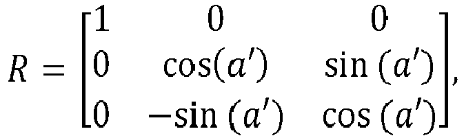
- 7. The method of
EEE 2, wherein the scaling vector comprises
- 8. The method of
EEE 1, wherein the first color space is the Rec. 709 YCbCr color space, the second color space is the ST 2084 IPT color space (IPT-PQ) and the color-rotation matrix comprises
- 9. The method of EEE 3, wherein the reshaping matrix comprises:

- 10. The method of
EEE 1, further comprising:- receiving an input image in the second color space (232);
- applying (510) the color-rotation matrix to the input image to generate a color-rotated image; and
- encoding (310) the color-rotated image using an encoder to generate a coded image;
- 11. The method of
EEE 2, further comprising:- receiving an input image (232) in the second color space;
- applying (510) the reshaping matrix to the input image to generate a reshaped image; and
- encoding (310) the reshaped image using an encoder to generate a coded image;
- 12. The method of
EEE 10 or EEE 11, further comprising:
applying a tone-mapping function (305) to luminance values of the reshaped image before the encoding step. - 13. The method of EEE 11, further comprising:
signaling information based on the reshaping matrix to a decoder as metadata. - 14. The method of EEE 11, wherein the metadata comprise:
- a flag indicating the presence or not of a color-rotation and scaling matrix; and
- a plurality of coefficients based on the color-rotation and scaling matrix when the flag indicates the presence of the color-rotation and scaling matrix.
- 15. The method of EEE 3, wherein the second color space comprises an IPT color space, and in a color converter, a default LMS to IPT conversion matrix is replaced by a product of the default LMS to IPT conversion matrix with the color reshaping matrix.
- 16. In a decoder, a method to reconstruct an input image coded in a reshaped color space, the method comprising:
- receiving a coded input image (312) in a reshaped color space, wherein the reshaped color space is generated by rotating chroma components of a preferred color space to approximate one or more parameters of a legacy color space;
- accessing metadata (309) transmitted from an encoder to the decoder, wherein the metadata are associated with the coded input image and comprise:
- a flag indicating the presence or not of a color-rotation and scaling matrix; and
- a plurality of coefficients for the color-rotation and scaling matrix when the flag indicates the presence of the color-rotation and scaling matrix;
- decoding (315) the coded input image to generate a decoded image in the reshaped color space; and
- generating a decoded image in the preferred color space based on the decoded image in the reshaped color space and the color-rotation and scaling matrix.
- 17. The method of EEE 16, wherein the one or more parameters of the legacy color space comprise a measure of color hue or saturation.
- 18. The method of EEE 16, wherein the legacy color space comprises a gamma-coded YCbCr color space and the preferred color space comprises a PQ-coded IPT color space.
- 19. A method to improve backward compatible decoding, the method comprising:
- receiving an input image in a preferred color space;
- accessing a hue rotation function, wherein for a hue value of a pixel in the input image in the preferred color space, the hue rotation function generates a rotated hue output value that matches according to a hue-cost criterion a hue value in a legacy color space;
- generating a reshaped image based on the input image and the hue rotation function; and
- encoding the reshaped image to generate a coded reshaped image.
- 20. The method of EEE 19, further comprising:
- accessing a saturation scaling function, wherein for the hue value of a pixel in the input image in the preferred color space, the saturation scaling function generates a hue value with scaled saturation that matches according to a saturation-cost criterion a hue saturation value in the legacy color space; and
- generating the reshaped image based on the input image, the hue rotation function, and the saturation scaling function.
- 21. In a decoder, a method to reconstruct an input image coded in a reshaped color space, the method comprising:
- accessing an input image encoded in a reshaped color space;
- accessing metadata associated with the input image, wherein the metadata comprise data associated with a hue rotation function used to translate the input image from a preferred color space to the reshaped color space, wherein for a hue value of a pixel in the input image in the preferred color space, the hue rotation function generates a rotated hue output value that matches according to a hue-cost criterion a hue value in a legacy color space; and
- generating an output image in the preferred color space based on the input image and the data associated with the hue rotation function.
- 22. The method of EEE 21, wherein the metadata further comprise data associated with a saturation scaling function used to translate the input image from the preferred color space to the reshaped color space, wherein for the hue value of a pixel in the input image in the preferred color space, the saturation scaling function generates a hue value with scaled saturation that matches according to a saturation-cost criterion a hue saturation value in the legacy color space; and
generating the output image in the preferred color space based on the input image and the data associated with the hue rotation function and the saturation scaling function. - 23. An apparatus comprising a processor and configured to perform any one of the methods recited in EEEs 1-22.
- 24. A non-transitory computer-readable storage medium having stored thereon computer-executable instruction for executing a method with one or more processors in accordance with any of the EEEs 1-22.
Claims (15)
- A method to improve processing for high-dynamic range images, the method comprising:accessing with a processor an input image (202) in a linear RGB color space;generating (220) a first image in an LMS color space by applying an RGB to LMS color transformation to the input image (202), wherein the RGB to LMS transformation comprises
 applying (215) a non-linear function to each color component of the first image to generate color components of a second image in a non-linear LMS color space; andgenerating (230) an output image in an ICtCp color space by applying a 3x3 color transformation matrix to the color components of the second image, wherein the 3x3 color transformation matrix comprises:
- The method of claim 1, wherein the non-linear function comprises an inverse of an electro-optical transfer function.
- The method of claim 2, wherein the electro-optical transfer function is determined according to the SMPTE ST 2084 specification.
- The method of claim 1, wherein the non-linear function is based on the Hybrid Log-Gamma (HLG) function.
- The method of claim 1, wherein the linear RGB color space comprises the RGB BT. 2020 color space.
- In a receiver, a method to reconstruct an input image (202) coded in an ICtCp color space, the method comprising:receiving (302) the input image (202) in the ICtCp color space;applying (305) a first 3 x 3 color transformation matrix to the input image (202) to generate a first image in a first color space, wherein the first 3x3 color transformation matrix comprises an inverse of
 applying (215) a non-linear function to each color component of the first image to generate a second image; andapplying (320) a second 3x3 color transformation matrix to the second image to generate an output image in a linear RGB color space, wherein the second 3x3 color transformation matrix comprises an inverse of
- The method of claim 6, wherein the linear RGB color space comprises the RGB BT. 2020 color space.
- The method of claim 6, wherein the non-linear function comprises an electro-optical transfer function.
- The method of claim 8, wherein the electro-optical transfer function (215) is determined according to the SMPTE ST 2084 specification.
- The method of claim 6, wherein the non-linear function is based on the Hybrid Log-Gamma (HLG) function.
- The method of claim 6 wherein the inverse of


- The method of claim 6, wherein the inverse of


- In a receiver, a method to reconstruct an input image (202) coded in an ICtCp color space, the method comprising:receiving (302) the input image (202) in the ICtCp color space;applying (305) a first 3 x 3 color transformation matrix to the input image (202) to generate a first image in a first color space, wherein the first 3x3 color transformation matrix comprises an inverse of
 applying (215) a non-linear function to each color component of the first image to generate a second image; andapplying (320) a second 3x3 color transformation matrix to the second image to generate a third image in the XYZ color space, wherein the second 3x3 color transformation matrix comprises
- An apparatus to improve processing for high-dynamic range images, the apparatus comprising a processor,wherein the processor is configured to:access with the processor an input image (202) in a linear RGB color space;generate (220) a first image in an LMS color space by applying an RGB to LMS color transformation to the input image (202), wherein the RGB to LMS transformation comprises
 applying (215) a non-linear function to each color component of the first image to generate color components of a second image in a non-linear LMS color space; andgenerating (230) an output image in an ICtCp color space by applying a 3x3 color transformation matrix to the color components of the second image, wherein the 3x3 color transformation matrix comprises: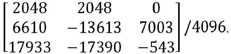
- A non-transitory computer-readable storage media having stored thereon computer-executable instructions for executing a method with one or more processors to improve processing for high-dynamic range images, the method comprising:accessing with the one or more processors an input image (202) in a linear RGB color space;generating (220) a first image in an LMS color space by applying an RGB to LMS color transformation to the input image (202), wherein the RGB to LMS transformation comprises
 applying (215) a non-linear function to each color component of the first image to generate color components of a second image in a non-linear LMS color space; andgenerating (230) an output image in an ICtCp color space by applying a 3x3 color transformation matrix to the color components of the second image, wherein the 3x3 color transformation matrix comprises:
Applications Claiming Priority (7)
| Application Number | Priority Date | Filing Date | Title |
|---|---|---|---|
| US201562200797P | 2015-08-04 | 2015-08-04 | |
| US201562202980P | 2015-08-10 | 2015-08-10 | |
| US201662278362P | 2016-01-13 | 2016-01-13 | |
| US201662300012P | 2016-02-25 | 2016-02-25 | |
| US201662302073P | 2016-03-01 | 2016-03-01 | |
| PCT/US2016/045362 WO2017024042A2 (en) | 2015-08-04 | 2016-08-03 | Signal reshaping for high dynamic range signals |
| EP16757757.6A EP3332550B1 (en) | 2015-08-04 | 2016-08-03 | Signal reshaping for high dynamic range signals |
Related Parent Applications (2)
| Application Number | Title | Priority Date | Filing Date |
|---|---|---|---|
| EP16757757.6A Division-Into EP3332550B1 (en) | 2015-08-04 | 2016-08-03 | Signal reshaping for high dynamic range signals |
| EP16757757.6A Division EP3332550B1 (en) | 2015-08-04 | 2016-08-03 | Signal reshaping for high dynamic range signals |
Publications (1)
| Publication Number | Publication Date |
|---|---|
| EP4210041A1 true EP4210041A1 (en) | 2023-07-12 |
Family
ID=56802666
Family Applications (3)
| Application Number | Title | Priority Date | Filing Date |
|---|---|---|---|
| EP23158888.0A Withdrawn EP4207178A1 (en) | 2015-08-04 | 2016-08-03 | Signal reshaping for high dynamic range signals |
| EP16757757.6A Active EP3332550B1 (en) | 2015-08-04 | 2016-08-03 | Signal reshaping for high dynamic range signals |
| EP23158881.5A Withdrawn EP4210041A1 (en) | 2015-08-04 | 2016-08-03 | Signal reshaping for high dynamic range signals |
Family Applications Before (2)
| Application Number | Title | Priority Date | Filing Date |
|---|---|---|---|
| EP23158888.0A Withdrawn EP4207178A1 (en) | 2015-08-04 | 2016-08-03 | Signal reshaping for high dynamic range signals |
| EP16757757.6A Active EP3332550B1 (en) | 2015-08-04 | 2016-08-03 | Signal reshaping for high dynamic range signals |
Country Status (10)
| Country | Link |
|---|---|
| US (17) | US10432977B2 (en) |
| EP (3) | EP4207178A1 (en) |
| JP (2) | JP6320440B2 (en) |
| KR (3) | KR102188460B1 (en) |
| CN (2) | CN110267046B (en) |
| BR (2) | BR112018001465B1 (en) |
| CA (2) | CA2994282C (en) |
| RU (3) | RU2693687C1 (en) |
| TW (3) | TWI756146B (en) |
| WO (1) | WO2017024042A2 (en) |
Families Citing this family (37)
| Publication number | Priority date | Publication date | Assignee | Title |
|---|---|---|---|---|
| KR102243844B1 (en) | 2015-09-23 | 2021-04-22 | 애리스 엔터프라이지즈 엘엘씨 | High dynamic range adaptation operations in video decoder |
| CN106937121B (en) * | 2015-12-31 | 2021-12-10 | 中兴通讯股份有限公司 | Image decoding and encoding method, decoding and encoding device, decoder and encoder |
| EP3367659A1 (en) * | 2017-02-28 | 2018-08-29 | Thomson Licensing | Hue changing color gamut mapping |
| US11158032B2 (en) | 2017-03-20 | 2021-10-26 | Dolby Laboratories Licensing Corporation | Perceptually preserving scene-referred contrasts and chromaticities |
| US11288781B2 (en) | 2017-06-16 | 2022-03-29 | Dolby Laboratories Licensing Corporation | Efficient end-to-end single layer inverse display management coding |
| US10769817B2 (en) | 2017-08-07 | 2020-09-08 | Samsung Display Co., Ltd. | Measures for image testing |
| TWI650998B (en) | 2017-12-15 | 2019-02-11 | Mstar Semiconductor, Inc. | Format conversion circuit and related method applied to set-top box |
| UA130140C2 (en) * | 2018-02-14 | 2025-11-26 | Долбі Лабораторіс Лайсензін Корпорейшн | Image conversion in video encoding using optimization of distortion dependency on transmission speed |
| WO2019199701A1 (en) * | 2018-04-09 | 2019-10-17 | Dolby Laboratories Licensing Corporation | Hdr image representations using neural network mappings |
| US10917583B2 (en) | 2018-04-27 | 2021-02-09 | Apple Inc. | Standard and high dynamic range display systems and methods for high dynamic range displays |
| GB2588004B (en) | 2018-06-05 | 2023-03-01 | Beijing Bytedance Network Tech Co Ltd | Interaction between IBC and affine |
| CN110691277B (en) * | 2018-07-05 | 2024-03-05 | 华为技术有限公司 | Video signal processing method and device |
| KR102784625B1 (en) * | 2018-11-01 | 2025-03-19 | 세종대학교산학협력단 | Method and apparatus for encoding/decoding image using transformation of axis of color coordinate |
| JP7324841B2 (en) | 2018-11-10 | 2023-08-10 | 北京字節跳動網絡技術有限公司 | Video data processing method, apparatus, storage medium and storage method |
| CN109685859B (en) * | 2018-12-24 | 2021-06-08 | 哈尔滨工业大学(深圳) | Three-dimensional color automatic adjustment method based on 3D lookup table |
| US12022080B2 (en) | 2019-03-01 | 2024-06-25 | Lg Electronics Inc. | Image coding method based on LMCS, and device therefor |
| WO2020180044A1 (en) * | 2019-03-01 | 2020-09-10 | 엘지전자 주식회사 | Lmcs-based image coding method and device therefor |
| KR20250121454A (en) * | 2019-03-12 | 2025-08-12 | 프라운호퍼-게젤샤프트 추르 푀르데룽 데어 안제반텐 포르슝 에 파우 | Selective Inter-Component Transform (ICT) for Image and Video Coding |
| CN110189687B (en) * | 2019-06-04 | 2020-10-09 | 深圳市摩西尔电子有限公司 | Method and device for carrying out image transformation on LED module image |
| EP4005208B1 (en) * | 2019-07-30 | 2025-10-08 | Dolby Laboratories Licensing Corporation | Electro-optical transfer function conversion and signal legalization |
| CN112689137B (en) | 2019-10-18 | 2022-05-10 | 华为技术有限公司 | A video signal processing method and device |
| JP7434554B2 (en) * | 2019-12-06 | 2024-02-20 | ドルビー ラボラトリーズ ライセンシング コーポレイション | Cascade prediction |
| JP7309081B2 (en) * | 2020-04-03 | 2023-07-14 | ドルビー ラボラトリーズ ライセンシング コーポレイション | Blind local reshaping in HDR imaging |
| EP4136634B1 (en) * | 2020-04-17 | 2026-03-25 | Dolby Laboratories Licensing Corporation | Chromatic ambient light correction |
| WO2021216607A1 (en) * | 2020-04-21 | 2021-10-28 | Dolby Laboratories Licensing Corporation | Reshaping functions for hdr imaging with continuity and reversibility constraints |
| PH12022552822A1 (en) | 2020-04-22 | 2024-02-12 | Dolby Laboratories Licensing Corp | Iterative optimization of reshaping functions in single-layer hdr image codec |
| US11412174B2 (en) | 2020-09-22 | 2022-08-09 | Microsoft Technology Licensing, Llc | Efficient electro-optical transfer function (EOTF) curve for standard dynamic range (SDR) content |
| ES3062794T3 (en) | 2020-10-02 | 2026-04-14 | Dolby Laboratories Licensing Corp | Adaptive local reshaping for sdr-to-hdr up-conversion |
| EP4229869A1 (en) | 2020-10-14 | 2023-08-23 | Dolby Laboratories Licensing Corporation | Color transformation for hdr video with a coding-efficiency constraint |
| US12549766B2 (en) | 2021-06-01 | 2026-02-10 | Dolby Laboratories Licensing Corporation | Rotation-enabled high dynamic range video encoding |
| PL4352964T3 (en) | 2021-06-08 | 2025-04-22 | Dolby Laboratories Licensing Corporation | Chained reshaping function optimization |
| JP7827882B2 (en) * | 2022-03-18 | 2026-03-10 | ドルビー ラボラトリーズ ライセンシング コーポレイション | Image optimization in mobile capture and editing applications |
| CN115147308B (en) * | 2022-07-05 | 2025-06-24 | 浙江大学 | A method to improve detail preservation performance in global tone mapping of HDR images |
| CN117575954A (en) * | 2022-08-04 | 2024-02-20 | 浙江宇视科技有限公司 | Color correction matrix optimization method, device, electronic equipment and medium |
| EP4339901A1 (en) * | 2022-09-19 | 2024-03-20 | Tata Consultancy Services Limited | System and method for generating hyperspectral artificial vision for machines |
| US12587353B2 (en) | 2023-04-13 | 2026-03-24 | Western Carolina University | Signal sampling and reconstruction below the nyquist rate |
| WO2025006041A1 (en) * | 2023-06-30 | 2025-01-02 | Purdue Research Foundation | Method for developing tissue-specific color chart |
Citations (5)
| Publication number | Priority date | Publication date | Assignee | Title |
|---|---|---|---|---|
| JP2008040305A (en) * | 2006-08-09 | 2008-02-21 | Nanao Corp | Display device, display system, and RGB signal processing method |
| US8593480B1 (en) | 2011-03-15 | 2013-11-26 | Dolby Laboratories Licensing Corporation | Method and apparatus for image data transformation |
| WO2014130343A2 (en) | 2013-02-21 | 2014-08-28 | Dolby Laboratories Licensing Corporation | Display management for high dynamic range video |
| WO2014160705A1 (en) | 2013-03-26 | 2014-10-02 | Dolby Laboratories Licensing Corporation | Encoding perceptually-quantized video content in multi-layer vdr coding |
| US9077994B2 (en) | 2011-12-06 | 2015-07-07 | Dolby Laboratories Licensing Corporation | Device and method of improving the perceptual luminance nonlinearity-based image data exchange across different display capabilities |
Family Cites Families (67)
| Publication number | Priority date | Publication date | Assignee | Title |
|---|---|---|---|---|
| JPS5141557B2 (en) | 1972-09-04 | 1976-11-10 | ||
| JPS5141557Y2 (en) | 1973-06-05 | 1976-10-08 | ||
| JPS5141557U (en) | 1974-09-24 | 1976-03-27 | ||
| EP0586204B1 (en) * | 1992-09-02 | 1997-11-19 | Matsushita Electric Industrial Co., Ltd. | Image signal processing device |
| JP3414800B2 (en) * | 1992-09-02 | 2003-06-09 | 松下電器産業株式会社 | Image signal processing device |
| DE4306797C1 (en) * | 1993-03-04 | 1994-05-05 | Schneider Rundfunkwerke Ag | Generating colour pixels of TV image - providing projection system using coloured lasers supplied with colour tone signals converted from phosphor screen base system to laser projection base system |
| JPH11313219A (en) * | 1998-01-20 | 1999-11-09 | Fujitsu Ltd | Color data conversion method |
| US6335983B1 (en) | 1998-09-28 | 2002-01-01 | Eastman Kodak Company | Representing an extended color gamut digital image in a limited color gamut color space |
| US6766263B1 (en) * | 2000-04-26 | 2004-07-20 | Microsoft Corporation | Method of color capture calibration for digital capture devices |
| JP4197858B2 (en) * | 2001-08-27 | 2008-12-17 | 富士通株式会社 | Image processing program |
| JP2004040448A (en) | 2002-07-03 | 2004-02-05 | Panasonic Communications Co Ltd | Picture processing method and picture processor |
| US7142723B2 (en) | 2003-07-18 | 2006-11-28 | Microsoft Corporation | System and process for generating high dynamic range images from multiple exposures of a moving scene |
| JP4617644B2 (en) | 2003-07-18 | 2011-01-26 | ソニー株式会社 | Encoding apparatus and method |
| JP2005079834A (en) * | 2003-08-29 | 2005-03-24 | Pentax Corp | Color conversion matrix calculation method and image signal processing apparatus |
| JP2005184601A (en) | 2003-12-22 | 2005-07-07 | Fuji Xerox Co Ltd | Apparatus, method and program for image processing |
| CN101977329B (en) * | 2004-07-29 | 2012-10-03 | 微软公司 | Image processing using linear light values and other image processing improvements |
| US20060244983A1 (en) * | 2005-04-29 | 2006-11-02 | Huanzhao Zeng | Fast color mapping using primary adjustment with gamut adaptation |
| JP2007259124A (en) * | 2006-03-23 | 2007-10-04 | Konica Minolta Business Technologies Inc | Color conversion table creation method, information creation apparatus, recording medium, and image processing apparatus |
| US20070285434A1 (en) * | 2006-06-12 | 2007-12-13 | Hung-Shih Lin | Hue adjustor and method for adjusting hues for specific colors in an image |
| TW200808072A (en) * | 2006-07-17 | 2008-02-01 | Marketech Int Corp | Hue adjusting device |
| JP5141557B2 (en) | 2006-10-23 | 2013-02-13 | 株式会社ニコン | Image processing method, image processing program, image processing apparatus, camera |
| UA26453U (en) | 2007-04-18 | 2007-09-25 | Zoia Rudolfivna Ulberh | Method for treating inflammations and functional impairments of locomotor and hepatobiliary systems |
| KR101166388B1 (en) | 2007-08-28 | 2012-07-23 | 삼성전자주식회사 | Color space conversion apparatus and control method for thereof |
| CN101521001B (en) * | 2008-02-26 | 2011-04-27 | 瑞昱半导体股份有限公司 | Color correction method and device for display device |
| US20090220151A1 (en) * | 2008-02-29 | 2009-09-03 | Himax Technologies Limited | Device for adjusting image color difference value and adjusting method thereof |
| US20090285434A1 (en) | 2008-05-13 | 2009-11-19 | Jason Martin Williams | Earhook and earbud headset |
| US8477247B2 (en) * | 2008-09-30 | 2013-07-02 | Intel Corporation | Joint enhancement of lightness, color and contrast of images and video |
| US8831343B2 (en) * | 2009-01-19 | 2014-09-09 | Dolby Laboratories Licensing Corporation | Image processing and displaying methods for devices that implement color appearance models |
| JP5430218B2 (en) * | 2009-05-07 | 2014-02-26 | キヤノン株式会社 | Image processing apparatus and image processing method |
| CN101909215B (en) * | 2009-06-05 | 2012-04-18 | 华映视讯(吴江)有限公司 | Color conversion method and corresponding color display method thereof |
| KR101295881B1 (en) * | 2009-07-10 | 2013-08-12 | 엘지디스플레이 주식회사 | Method of correcting preferred color and display apparatus using the same |
| KR101482542B1 (en) * | 2010-07-22 | 2015-01-14 | 돌비 레버러토리즈 라이쎈싱 코오포레이션 | System, apparatus and methods for mapping between video ranges of image data and display |
| JP5663284B2 (en) * | 2010-12-06 | 2015-02-04 | 東芝テック株式会社 | Antenna switching system |
| JP5648496B2 (en) * | 2011-01-26 | 2015-01-07 | 村田機械株式会社 | Document reader |
| WO2012142285A2 (en) * | 2011-04-12 | 2012-10-18 | Dolby Laboratories Licensing Corporation | Quality assessment for images that have extended dynamic ranges or wide color gamuts |
| CN103493489B (en) | 2011-04-14 | 2016-10-19 | 杜比实验室特许公司 | Image prediction based on primary colors hierarchy model |
| JP5791643B2 (en) * | 2013-01-29 | 2015-10-07 | 京セラドキュメントソリューションズ株式会社 | Image processing apparatus and image forming apparatus |
| JP6251489B2 (en) * | 2013-03-28 | 2017-12-20 | 株式会社 資生堂 | Image analysis apparatus, image analysis method, and image analysis program |
| EP3011741B1 (en) * | 2013-06-17 | 2018-03-07 | Dolby Laboratories Licensing Corporation | Adaptive reshaping for layered coding of enhanced dynamic range signals |
| EP3094096B1 (en) | 2014-01-06 | 2018-09-26 | LG Electronics Inc. | Method and device for transmitting and receiving broadcast signal on basis of color gamut resampling |
| TW201532427A (en) * | 2014-01-10 | 2015-08-16 | Thomson Licensing | Method for obtaining network information by a client terminal configured for receiving a multimedia content divided into segments |
| US9277196B2 (en) * | 2014-02-19 | 2016-03-01 | DDD IP Ventures, Ltd. | Systems and methods for backward compatible high dynamic range/wide color gamut video coding and rendering |
| WO2015167460A1 (en) * | 2014-04-29 | 2015-11-05 | Hewlett Packard Development Company, L.P. | Imager calibration via modeled responses to importance-weighted color sample data |
| EP2961168A1 (en) * | 2014-06-27 | 2015-12-30 | Thomson Licensing | Method and apparatus for predicting image samples for encoding or decoding |
| KR101794817B1 (en) | 2014-09-26 | 2017-11-07 | 돌비 레버러토리즈 라이쎈싱 코오포레이션 | Encoding and decoding perceptually-quantized video content |
| US9736335B2 (en) * | 2015-04-15 | 2017-08-15 | Apple Inc. | Techniques for advanced chroma processing |
| US10484684B2 (en) * | 2015-04-22 | 2019-11-19 | Dolby Laboratories Licensing Corporation | Signal reshaping and coding in the IPT-PQ color space |
| WO2016186547A1 (en) * | 2015-05-21 | 2016-11-24 | Telefonaktiebolaget Lm Ericsson (Publ) | Pixel pre-processing and encoding |
| WO2016195576A1 (en) * | 2015-06-05 | 2016-12-08 | Telefonaktiebolaget Lm Ericsson (Publ) | Encoding a pixel of an input video sequence |
| EP3110124A1 (en) * | 2015-06-25 | 2016-12-28 | Thomson Licensing | Hue changing color gamut mapping |
| EP3314892A4 (en) * | 2015-06-26 | 2018-08-22 | Telefonaktiebolaget LM Ericsson (publ) | Encoding and decoding of pictures in a video |
| GB2539917B (en) * | 2015-06-30 | 2021-04-07 | British Broadcasting Corp | Method and apparatus for conversion of HDR signals |
| EP3320675B1 (en) * | 2015-07-10 | 2025-12-10 | Telefonaktiebolaget LM Ericsson (publ) | Pixel pre-processing and encoding |
| WO2017015564A1 (en) * | 2015-07-22 | 2017-01-26 | Arris Enterprises Llc | System for coding high dynamic range and wide color gamut sequences |
| TWI764870B (en) * | 2015-07-28 | 2022-05-21 | 法商內數位麥德遜專利控股有限公司 | Video signal processing device and method |
| WO2017032646A1 (en) * | 2015-08-24 | 2017-03-02 | Thomson Licensing | Coding and decoding method and corresponding devices |
| EP3354032A1 (en) * | 2015-09-21 | 2018-08-01 | VID SCALE, Inc. | Inverse reshaping for high dynamic range video coding |
| KR102243844B1 (en) * | 2015-09-23 | 2021-04-22 | 애리스 엔터프라이지즈 엘엘씨 | High dynamic range adaptation operations in video decoder |
| WO2017083784A1 (en) * | 2015-11-11 | 2017-05-18 | Apple Inc. | Adaptive chroma downsampling and color space conversion techniques |
| WO2017108906A1 (en) * | 2015-12-21 | 2017-06-29 | Koninklijke Philips N.V. | Optimizing high dynamic range images for particular displays |
| KR20170088303A (en) * | 2016-01-22 | 2017-08-01 | 한국전자통신연구원 | Method and apparatus for image signal conversion to reduce artifacts |
| US10397586B2 (en) * | 2016-03-30 | 2019-08-27 | Dolby Laboratories Licensing Corporation | Chroma reshaping |
| US10542296B2 (en) * | 2016-05-10 | 2020-01-21 | Dolby Laboratories Licensing Corporation | Chroma reshaping of HDR video signals |
| EP3340165A1 (en) * | 2016-12-20 | 2018-06-27 | Thomson Licensing | Method of color gamut mapping input colors of an input ldr content into output colors forming an output hdr content |
| EP3566429B1 (en) * | 2017-03-03 | 2021-09-15 | Dolby Laboratories Licensing Corporation | Color image modification with approximation function |
| WO2018175337A1 (en) * | 2017-03-20 | 2018-09-27 | Dolby Laboratories Licensing Corporation | Perceptually preserving scene-referred contrasts and chromaticities |
| GB2561395A (en) * | 2017-04-13 | 2018-10-17 | Sony Corp | Colour conversion |
-
2016
- 2016-03-17 JP JP2016054344A patent/JP6320440B2/en active Active
- 2016-08-03 CN CN201910669133.0A patent/CN110267046B/en active Active
- 2016-08-03 CA CA2994282A patent/CA2994282C/en active Active
- 2016-08-03 KR KR1020207022148A patent/KR102188460B1/en active Active
- 2016-08-03 WO PCT/US2016/045362 patent/WO2017024042A2/en not_active Ceased
- 2016-08-03 BR BR112018001465-6A patent/BR112018001465B1/en active IP Right Grant
- 2016-08-03 CA CA3086441A patent/CA3086441C/en active Active
- 2016-08-03 US US15/749,231 patent/US10432977B2/en active Active
- 2016-08-03 EP EP23158888.0A patent/EP4207178A1/en not_active Withdrawn
- 2016-08-03 EP EP16757757.6A patent/EP3332550B1/en active Active
- 2016-08-03 KR KR1020197020423A patent/KR102141193B1/en active Active
- 2016-08-03 KR KR1020187003386A patent/KR20180026517A/en not_active Ceased
- 2016-08-03 BR BR122022023327-9A patent/BR122022023327B1/en active IP Right Grant
- 2016-08-03 JP JP2018503569A patent/JP6531218B2/en active Active
- 2016-08-03 EP EP23158881.5A patent/EP4210041A1/en not_active Withdrawn
- 2016-08-03 CN CN201680045443.XA patent/CN107925770B/en active Active
- 2016-08-03 RU RU2018104936A patent/RU2693687C1/en active
- 2016-08-03 RU RU2019118419A patent/RU2736103C2/en active
- 2016-08-04 TW TW110122989A patent/TWI756146B/en active
- 2016-08-04 TW TW108131544A patent/TWI735036B/en active
- 2016-08-04 TW TW105124794A patent/TWI684166B/en active
-
2019
- 2019-08-06 US US16/532,924 patent/US11025961B2/en active Active
-
2020
- 2020-10-14 RU RU2020133656A patent/RU2762384C1/en active
-
2021
- 2021-04-20 US US17/234,815 patent/US11582490B2/en active Active
- 2021-04-20 US US17/234,816 patent/US11570480B2/en active Active
-
2022
- 2022-11-22 US US17/992,616 patent/US11979615B1/en active Active
- 2022-11-22 US US17/992,603 patent/US11785263B2/en active Active
-
2023
- 2023-06-27 US US18/215,129 patent/US11924477B2/en active Active
- 2023-10-31 US US18/385,724 patent/US11910025B1/en active Active
-
2024
- 2024-01-05 US US18/405,874 patent/US12028555B2/en active Active
- 2024-03-26 US US18/616,959 patent/US12041275B1/en active Active
- 2024-04-09 US US18/630,786 patent/US12120357B2/en active Active
- 2024-05-30 US US18/678,794 patent/US12120358B2/en active Active
- 2024-07-22 US US18/780,325 patent/US12167048B2/en active Active
- 2024-09-27 US US18/899,400 patent/US12200271B1/en active Active
- 2024-11-26 US US18/961,211 patent/US12621501B2/en active Active
-
2026
- 2026-02-04 US US19/530,173 patent/US12707100B2/en active Active
- 2026-02-27 US US19/552,201 patent/US12671850B2/en active Active
Patent Citations (5)
| Publication number | Priority date | Publication date | Assignee | Title |
|---|---|---|---|---|
| JP2008040305A (en) * | 2006-08-09 | 2008-02-21 | Nanao Corp | Display device, display system, and RGB signal processing method |
| US8593480B1 (en) | 2011-03-15 | 2013-11-26 | Dolby Laboratories Licensing Corporation | Method and apparatus for image data transformation |
| US9077994B2 (en) | 2011-12-06 | 2015-07-07 | Dolby Laboratories Licensing Corporation | Device and method of improving the perceptual luminance nonlinearity-based image data exchange across different display capabilities |
| WO2014130343A2 (en) | 2013-02-21 | 2014-08-28 | Dolby Laboratories Licensing Corporation | Display management for high dynamic range video |
| WO2014160705A1 (en) | 2013-03-26 | 2014-10-02 | Dolby Laboratories Licensing Corporation | Encoding perceptually-quantized video content in multi-layer vdr coding |
Non-Patent Citations (4)
| Title |
|---|
| "High Dynamic Range Electro-optical Transfer Function of Mastering Reference Displays", SMPTE ST 2084:2014 SPECIFICATION, 16 August 2014 (2014-08-16) |
| F. EBNERM.D. FAIRCHILD: "Proc. 6th Color Imaging Conference: Color Science, Systems, and Applications", November 1998, IS&T, article "Development and testing of a color space (ipt) with improved hue uniformity", pages: 8 - 13 |
| ITU-R WP 6C VIA SC 29 SECRETARIAT: "Liaison Statement from ITU-R WP 6C", no. m37788, 12 February 2016 (2016-02-12), XP030268348, Retrieved from the Internet <URL:http://phenix.int-evry.fr/mpeg/doc_end_user/documents/114_San%20Diego/wg11/m37788-v1-m37788.zip 29n156263.doc> [retrieved on 20160212] * |
| TAORAN LU ET AL: "ITP Colour Space and Its Compression Performance for High Dynamic Range and Wide Colour Gamut Video Distribution", 5 February 2016 (2016-02-05), XP055282146, Retrieved from the Internet <URL:http://wwwen.zte.com.cn/endata/magazine/ztecommunications/2016/1/articles/201603/P020160311294995790791.pdf> [retrieved on 20160620] * |
Also Published As
Similar Documents
| Publication | Publication Date | Title |
|---|---|---|
| US12621501B2 (en) | Signal reshaping for high dynamic range signals | |
| HK40088762A (en) | Signal reshaping for high dynamic range signals | |
| HK40010357A (en) | Signal reshaping for high dynamic range signals | |
| HK40010357B (en) | Signal reshaping for high dynamic range signals |
Legal Events
| Date | Code | Title | Description |
|---|---|---|---|
| PUAI | Public reference made under article 153(3) epc to a published international application that has entered the european phase |
Free format text: ORIGINAL CODE: 0009012 |
|
| STAA | Information on the status of an ep patent application or granted ep patent |
Free format text: STATUS: THE APPLICATION HAS BEEN PUBLISHED |
|
| AC | Divisional application: reference to earlier application |
Ref document number: 3332550 Country of ref document: EP Kind code of ref document: P |
|
| AK | Designated contracting states |
Kind code of ref document: A1 Designated state(s): AL AT BE BG CH CY CZ DE DK EE ES FI FR GB GR HR HU IE IS IT LI LT LU LV MC MK MT NL NO PL PT RO RS SE SI SK SM TR |
|
| REG | Reference to a national code |
Ref country code: HK Ref legal event code: DE Ref document number: 40088762 Country of ref document: HK |
|
| STAA | Information on the status of an ep patent application or granted ep patent |
Free format text: STATUS: THE APPLICATION HAS BEEN WITHDRAWN |
|
| 18W | Application withdrawn |
Effective date: 20240108 |