EP4209815A1 - Photographing camera and unmanned aerial vehicle - Google Patents
Photographing camera and unmanned aerial vehicle Download PDFInfo
- Publication number
- EP4209815A1 EP4209815A1 EP21863712.2A EP21863712A EP4209815A1 EP 4209815 A1 EP4209815 A1 EP 4209815A1 EP 21863712 A EP21863712 A EP 21863712A EP 4209815 A1 EP4209815 A1 EP 4209815A1
- Authority
- EP
- European Patent Office
- Prior art keywords
- lens
- refractive power
- camera lens
- camera
- spherical surface
- Prior art date
- Legal status (The legal status is an assumption and is not a legal conclusion. Google has not performed a legal analysis and makes no representation as to the accuracy of the status listed.)
- Pending
Links
Images



Classifications
-
- G—PHYSICS
- G02—OPTICS
- G02B—OPTICAL ELEMENTS, SYSTEMS OR APPARATUS
- G02B13/00—Optical objectives specially designed for the purposes specified below
- G02B13/001—Miniaturised objectives for electronic devices, e.g. portable telephones, webcams, PDAs, small digital cameras
- G02B13/0015—Miniaturised objectives for electronic devices, e.g. portable telephones, webcams, PDAs, small digital cameras characterised by the lens design
- G02B13/002—Miniaturised objectives for electronic devices, e.g. portable telephones, webcams, PDAs, small digital cameras characterised by the lens design having at least one aspherical surface
- G02B13/0045—Miniaturised objectives for electronic devices, e.g. portable telephones, webcams, PDAs, small digital cameras characterised by the lens design having at least one aspherical surface having five or more lenses
-
- G—PHYSICS
- G02—OPTICS
- G02B—OPTICAL ELEMENTS, SYSTEMS OR APPARATUS
- G02B13/00—Optical objectives specially designed for the purposes specified below
- G02B13/001—Miniaturised objectives for electronic devices, e.g. portable telephones, webcams, PDAs, small digital cameras
- G02B13/0015—Miniaturised objectives for electronic devices, e.g. portable telephones, webcams, PDAs, small digital cameras characterised by the lens design
-
- G—PHYSICS
- G02—OPTICS
- G02B—OPTICAL ELEMENTS, SYSTEMS OR APPARATUS
- G02B13/00—Optical objectives specially designed for the purposes specified below
- G02B13/04—Reversed telephoto objectives
-
- G—PHYSICS
- G02—OPTICS
- G02B—OPTICAL ELEMENTS, SYSTEMS OR APPARATUS
- G02B9/00—Optical objectives characterised both by the number of the components and their arrangements according to their sign, i.e. + or -
- G02B9/64—Optical objectives characterised both by the number of the components and their arrangements according to their sign, i.e. + or - having more than six components
-
- B—PERFORMING OPERATIONS; TRANSPORTING
- B64—AIRCRAFT; AVIATION; COSMONAUTICS
- B64U—UNMANNED AERIAL VEHICLES [UAV]; EQUIPMENT THEREFOR
- B64U10/00—Type of UAV
- B64U10/10—Rotorcrafts
- B64U10/13—Flying platforms
- B64U10/14—Flying platforms with four distinct rotor axes, e.g. quadcopters
-
- B—PERFORMING OPERATIONS; TRANSPORTING
- B64—AIRCRAFT; AVIATION; COSMONAUTICS
- B64U—UNMANNED AERIAL VEHICLES [UAV]; EQUIPMENT THEREFOR
- B64U2101/00—UAVs specially adapted for particular uses or applications
- B64U2101/30—UAVs specially adapted for particular uses or applications for imaging, photography or videography
Definitions
- Embodiments of the present disclosure relate to the technical field of optical design and, more particularly, to a camera lens and an unmanned aerial vehicle.
- a camera lens is preferable for the application on a tripod head of a UAV to move flexibly, because it occupies a smaller volume and adds little weight to the whole UAV; on the other hand, a camera lens is supposed to capture a clearer picture, which needs to increase a size of an imaging surface to accommodate more pixels.
- the inventors have found that the above-related art has at least the following problems.
- the size of the imaging surface of a lens is inversely proportional to the size of the lens.
- an optical length of a focusing lens with a 4K or higher resolution and a 1-inch (16mm) imaging target surface available from the market is generally 40mm or more, that is to say, the miniaturization of the camera lens conflicts with the optimization of the imaging effect.
- the present disclosure provides a camera lens, including:
- the ninth lens is an aspherical lens and a surface thereof near an image side is concave.
- the second lens and the seventh lens are aspherical lenses.
- the first lens and the sixth lens are concave lenses
- the third lens, the fourth lens, the fifth lens, and the eighth lens are convex lenses.
- the camera lens satisfies a relationship below: ⁇ 6.5 ⁇ f 1 + f 2 + f 3 / f ⁇ 2.5 2.2 ⁇ TTL / f ⁇ 4.2 wherein f1 is an effective focal length of the first lens group, f2 is the effective focal length of the second lens group, f3 is the effective focal length of the third lens group, f is the effective focal length of the camera lens, and TTL is a total lens length of the camera lens.
- the camera lens further satisfies a relationship below: TTL / IH ⁇ 1.63 wherein TTL is the total lens length of the camera lens, and IH is a diagonal length of an effective pixel area on an imaging surface of the camera lens.
- the effective focal length of the first lens group satisfies a relationship below: ⁇ 65 ⁇ f 1 ⁇ ⁇ 10 wherein f1 is the effective focal length of the first lens group.
- the effective focal length of the second lens group satisfies a relationship below: ⁇ 11 ⁇ f 2 ⁇ 12 wherein f2 is the effective focal length of the second lens group.
- the effective focal length of the third lens group satisfies a relationship below: ⁇ 18 ⁇ f 3 ⁇ 45 wherein f3 is the effective focal length of the third lens group.
- the present disclosure provides an unmanned aerial vehicle, wherein the unmanned aerial vehicle include: a controller communicatively connected to the camera lens according to the first aspect.
- the present disclosure is advantageous in that unlike the prior art, the embodiments of the present disclosure provide a camera lens including, from an object side to an image side, a first lens group including a first lens having a negative refractive power and a second lens having a positive refractive power; a diaphragm; a second lens group including a third lens having a positive refractive power, a fourth lens having a positive refractive power, a fifth lens having a positive or negative refractive power, a sixth lens having a negative refractive power, and a seventh lens having a negative refractive power; a third lens group including an eighth lens having a positive refractive power and a ninth lens having a positive or negative refractive power.
- the camera lens provided by the embodiments of the present disclosure needs only nine lenses to achieve high-quality imaging, and the lens is small in size, short in length, and good in portability.
- the present disclosure provides a camera lens using a combination of a plastic aspherical surface, a spherical surface, and a compound lens, which produces an auto-focusing (AF) and fixed-focus camera lens having a 4K or higher resolution, a 1-inch (16mm) or bigger imaging target surface of the lens, and a 32mm or shorter optical length.
- AF auto-focusing
- FIG. 1 a schematic diagram of an application environment of a camera lens provided by an embodiment of the present disclosure is shown. As shown in FIG.
- the camera lens 2 provided by the present disclosure can be mounted on an unmanned aerial vehicle 1, and a controller (not shown) is provided in the unmanned aerial vehicle 1; the unmanned aerial vehicle 1 is communicatively connected to the camera lens 2 via the controller (not shown) to realize data interaction between the controller (not shown) and the camera lens 2. That is to say, the camera lens 2 can send a collected image to the controller (not shown), and the controller (not shown) can also issue a control instruction to the camera lens 2 for photographing.
- the camera lens includes, from an object side to an image side, a first lens group including a first lens having a negative refractive power and a second lens having a positive refractive power; a diaphragm; a second lens group including a third lens having a positive refractive power, a fourth lens having a positive refractive power, a fifth lens having a positive or negative refractive power, a sixth lens having a negative refractive power, and a seventh lens having a negative refractive power; a third lens group including an eighth lens having a positive refractive power and a ninth lens having a positive or negative refractive power.
- the ninth lens is an aspherical lens, and a surface thereof near the image side is concave. Further, the second lens and the seventh lens are aspherical lenses. Further, the first lens and the sixth lens are concave lenses, and the third lens, the fourth lens, the fifth lens, and the eighth lens are convex lenses.
- the camera lens satisfies a relationship below: ⁇ 6.5 ⁇ f 1 + f 2 + f 3 / f ⁇ 2.5 2.2 ⁇ TTL / f ⁇ 4.2
- f1 is an effective focal length (EFL) of the first lens group
- f2 is the effective focal length of the second lens group
- f3 is the effective focal length of the third lens group
- f is the effective focal length of the camera lens
- TTL is a total lens length of the camera lens.
- the camera lens further satisfies a relationship below: TTL / IH ⁇ 1.63 where TTL is the total lens length of the camera lens, and IH is a diagonal length of an effective pixel area on an imaging surface of the camera lens.
- the effective focal length of the first lens group satisfies a relationship below: ⁇ 65 ⁇ f 1 ⁇ ⁇ 10 where f1 is the effective focal length of the first lens group, that is, the first lens group has a negative refractive power.
- the effective focal length of the second lens group satisfies a relationship below: ⁇ 11 ⁇ f 2 ⁇ 12 where f2 is the effective focal length of the second lens group, that is, the second lens group has a positive or negative refractive power.
- the effective focal length of the third lens group satisfies a relationship below: ⁇ 18 ⁇ f 3 ⁇ 45 where f3 is the effective focal length of the third lens group, that is, the third lens group has a positive or negative refractive power.
- An embodiment of the present disclosure provides a camera lens.
- a camera lens Referring to FIG. 2 , an optical structure of the camera lens is shown, in which light from an object to be captured passes sequentially through a first lens group 10 (successively through a first lens 11 and a second lens 12), a diaphragm 40, a second lens group 20 (successively through a third lens 21, a fourth lens 22, a fifth lens 23, a sixth lens 24, and a seventh lens 25), and a third lens group 30 (successively through an eighth lens 31 and a ninth lens 32) to be focused, and then the object is imaged on an imaging surface 60 after the light passes through a plate glass 50.
- the diaphragm 40 is used for limiting a throughput of the light from the subject to be imaged;
- the plate glass 50 may be a structure like a filter, and in particular, a function thereof may depend on a glass material selected;
- the imaging surface 60 is an imaging target surface having a size of 1 inch (16mm) or more.
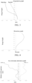
- FIG. 3 is an astigmatism graph (mm) of the camera lens shown in FIG. 2 , wherein an astigmatism in a sagittal plane is less than 0.3mm and the astigmatism in a meridian plane is less than 0.5mm, meeting a high standard;
- FIG. 4 is a distortion graph (%) of the camera lens shown in FIG.
- FIG. 5 is an axial chromatic aberration graph (mm) of the camera lens shown in FIG. 2 , wherein an axial chromatic aberration of red light (C light) having a wavelength of 0.6563 ⁇ m is controlled within 0.003mm, and the axial chromatic aberration of blue light (F light) having a wavelength of 0.4861 ⁇ m is controlled within 0.001mm, meeting a high standard.
- C light red light
- F light blue light
- the embodiment of the present disclosure employs a combination of plastic aspheric, spherical, and compound lenses to achieve an auto-focusing (hereinafter AF) and fixed-focus lens having a 4K or higher resolution, a 1-inch (16mm) or bigger imaging target surface of the lens, and a 32mm or shorter optical length.
- AF auto-focusing
- An embodiment of the present disclosure provides a camera lens.
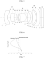
- a camera lens Referring to FIG. 6 , an optical structure of the camera lens is shown, in which light from an object to be captured passes sequentially through the first lens group 10 (sequentially through the first lens 11 and the second lens 12), the diaphragm 40, the second lens group 20 (sequentially through the third lens 21, the fourth lens 22, the fifth lens 23, the sixth lens 24, and the seventh lens 25), and the third lens group 30 (sequentially through the eighth lens 31 and the ninth lens 32) to be focused, and then the object is imaged on the imaging surface 60 after the light passes through the plate glass 50.
- the diaphragm 40 is used for limiting the throughput of the light from the subject to be imaged;
- the plate glass 50 may be a structure like a filter, and in particular, the function thereof may depend on the glass material selected;
- the imaging surface 60 is an imaging target surface having a size of 1 inch (16mm) or more.
- FIG. 7 is an astigmatism graph (mm) of the camera lens shown in FIG. 6 , wherein an astigmatism in a sagittal plane is less than 0.3mm and the astigmatism in a meridian plane is less than 0.7mm, meeting a high standard;
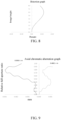
- FIG. 8 is a distortion graph (%) of the camera lens shown in FIG.
- FIG. 9 is an axial chromatic aberration graph (mm) of the camera lens shown in FIG. 6 , wherein an axial chromatic aberration of red light (C light) having a wavelength of 0.6563 ⁇ m is controlled within 0.003mm, and the axial chromatic aberration of blue light (F light) having a wavelength of 0.4861 ⁇ m is controlled within 0.001mm, meeting a high standard.
- C light red light
- F light blue light
- the embodiment of the present disclosure employs a combination of plastic aspheric, spherical, and compound lenses to achieve an auto-focusing (hereinafter AF) and fixed-focus lens having a 4K or higher resolution, a 1-inch (16mm) or bigger imaging target surface of the lens, and a 32mm or shorter optical length.
- AF auto-focusing
- An embodiment of the present disclosure provides a camera lens.
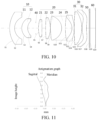
- FIG. 10 an optical structure of the camera lens is shown, in which light from an object to be captured passes sequentially through the first lens group 10 (successively through the first lens 11 and the second lens 12), the diaphragm 40, the second lens group 20 (successively through the third lens 21, the fourth lens 22, the fifth lens 23, the sixth lens 24, and the seventh lens 25), and the third lens group 30 (successively through the eighth lens 31 and the ninth lens 32) to be focused, and the object is then imaged on the imaging surface 60 after the light passes through the plate glass 50.
- the diaphragm 40 is used for limiting the throughput of light from the subject to be imaged
- the plate glass 50 may be a structure like a filter, and in particular, the function thereof may depend on the glass material selected;
- the imaging surface 60 is an imaging target surface having a size of 1 inch (16mm) or more.
- FIG. 11 is an astigmatism graph (mm) of the camera lens shown in FIG. 10 , wherein an astigmatism in a sagittal plane is less than 0.1mm and the astigmatism in a meridian plane is less than 0.1mm, meeting a high standard;
- FIG. 12 is a distortion graph (%) of the camera lens shown in FIG.
- FIG. 13 is an axial chromatic aberration graph (mm) of the camera lens shown in FIG. 10 , wherein an axial chromatic aberration of red light (C light) having a wavelength of 0.6563 ⁇ m is controlled within 0.005mm, and the axial chromatic aberration of blue light (F light) having a wavelength of 0.4861 ⁇ m is controlled within 0.002mm, meeting a high standard.
- C light red light
- F light blue light
- the embodiment of the present disclosure employs a combination of plastic aspheric, spherical, and compound lenses to achieve an auto-focusing (hereinafter AF) and fixed-focus lens having a 4K or higher resolution, a 1-inch (16mm) or bigger imaging target surface of the lens, and a 32mm or shorter optical length.
- AF auto-focusing
- An embodiment of the present disclosure provides a camera lens.
- a camera lens Referring to FIG. 14 , an optical structure of the camera lens is shown, in which light from an object to be captured passes through the first lens group 10 (successively through the first lens 11 and the second lens 12), the diaphragm 40, the second lens group 20 (successively through the third lens 21, the fourth lens 22, the fifth lens 23, the sixth lens 24, and the seventh lens 25), and the third lens group 30 (successively through the eighth lens 31 and the ninth lens 32) to be focused, and then the object is imaged on the imaging surface 60 after the light passes through the plate glass 50.
- the diaphragm 40 is used for limiting the throughput of light of the subject to be imaged
- the plate glass 50 may be a structure like a filter, and in particular, the function thereof may depend on the glass material selected;
- the imaging surface 60 is an imaging target surface having a size of 1 inch (16mm) or more.
- FIGS. 15 , 16 , and 17 graphs capable of characterizing the image quality of the camera lens are obtained as shown in FIGS. 15 , 16 , and 17 .
- FIG. 15 is an astigmatism graph (mm) of the camera lens shown in FIG. 14 , wherein an astigmatism in a sagittal plane is less than 0.1mm and the astigmatism in a meridian plane is less than 0.1mm, meeting a high standard;
- FIG. 16 is a distortion graph (%) of the camera lens shown in FIG.
- FIG. 17 is an axial chromatic aberration graph (mm) of the camera lens shown in FIG. 14 , wherein an axial chromatic aberration of red light (C light) having a wavelength of 0.6563 ⁇ m is controlled within 0.005mm, and the axial chromatic aberration of blue light (F light) having a wavelength of 0.4861 ⁇ m is controlled within 0.002mm, meeting a high standard.
- C light red light
- F light blue light
- the embodiment of the present disclosure employs a combination of plastic aspheric, spherical, and compound lenses to achieve an auto-focusing (hereinafter AF) and fixed-focus lens having a 4K or higher resolution, a 1-inch (16mm) or bigger imaging target surface of the lens, and a 32mm or shorter optical length.
- AF auto-focusing
- the embodiments of the present disclosure provide a camera lens, and the camera lens includes, from an object side to an image side, a first lens group including a first lens having a negative refractive power and a second lens having a positive refractive power; a diaphragm; a second lens group including a third lens having a positive refractive power, a fourth lens having a positive refractive power, a fifth lens having a positive or negative refractive power, a sixth lens having a negative refractive power, and a seventh lens having a negative refractive power; a third lens group including an eighth lens having a positive refractive power and a ninth lens having a positive or negative refractive power.
- the camera lens provided by the embodiments of the present disclosure needs only nine lenses to achieve high-quality imaging, and the lens is small in size, short in length, and good in portability.
Landscapes
- Physics & Mathematics (AREA)
- General Physics & Mathematics (AREA)
- Optics & Photonics (AREA)
- Lenses (AREA)
- Engineering & Computer Science (AREA)
- Mechanical Engineering (AREA)
- Remote Sensing (AREA)
- Aviation & Aerospace Engineering (AREA)
Abstract
Description
- The present application claims the priority to
Chinese patent application No. 2020109221166, entitled "Camera Lens and Unmanned Aerial Vehicle", filed on September 4, 2020 - Embodiments of the present disclosure relate to the technical field of optical design and, more particularly, to a camera lens and an unmanned aerial vehicle.
- With the development of science and technology, high-tech camera products such as miniature single-lens reflex cameras and unmanned aerial vehicles (UAV) pose higher requirements for a camera lens, especially for a small lens module with a large target surface. On the one hand, a smaller camera lens is preferable for the application on a tripod head of a UAV to move flexibly, because it occupies a smaller volume and adds little weight to the whole UAV; on the other hand, a camera lens is supposed to capture a clearer picture, which needs to increase a size of an imaging surface to accommodate more pixels.
- In the implementation of the embodiments of the present disclosure, the inventors have found that the above-related art has at least the following problems. Conventionally, the size of the imaging surface of a lens is inversely proportional to the size of the lens. For example, an optical length of a focusing lens with a 4K or higher resolution and a 1-inch (16mm) imaging target surface available from the market is generally 40mm or more, that is to say, the miniaturization of the camera lens conflicts with the optimization of the imaging effect.
- In view of the above-mentioned disadvantages of the prior art, it is an object of embodiments of the present disclosure to provide a camera lens and an unmanned aerial vehicle having a small volume and a good imaging effect.
- The object of the embodiments of the present disclosure is achieved through the following technical solution.
- To solve the above technical problem, according to a first aspect, the present disclosure provides a camera lens, including:
- a first lens group including a first lens having a negative refractive power and a second lens having a positive refractive power;
- a diaphragm;
- a second lens group including a third lens having a positive refractive power, a fourth lens having a positive refractive power, a fifth lens having a positive or negative refractive power, a sixth lens having a negative refractive power, and a seventh lens having a negative refractive power; and
- a third lens group including an eighth lens having a positive refractive power and a ninth lens having a positive or negative refractive power.
- In some embodiments, the ninth lens is an aspherical lens and a surface thereof near an image side is concave.
- In some embodiments, the second lens and the seventh lens are aspherical lenses.
- In some embodiments, the first lens and the sixth lens are concave lenses, and the third lens, the fourth lens, the fifth lens, and the eighth lens are convex lenses.
- In some embodiments, the camera lens satisfies a relationship below:


- In some embodiments, the camera lens further satisfies a relationship below:

- In some embodiments, the effective focal length of the first lens group satisfies a relationship below:

- In some embodiments, the effective focal length of the second lens group satisfies a relationship below:

- In some embodiments, the effective focal length of the third lens group satisfies a relationship below:

- To solve the above technical problem, according to a second aspect, the present disclosure provides an unmanned aerial vehicle, wherein the unmanned aerial vehicle include: a controller communicatively connected to the camera lens according to the first aspect.
- Compared with the prior art, the present disclosure is advantageous in that unlike the prior art, the embodiments of the present disclosure provide a camera lens including, from an object side to an image side, a first lens group including a first lens having a negative refractive power and a second lens having a positive refractive power; a diaphragm; a second lens group including a third lens having a positive refractive power, a fourth lens having a positive refractive power, a fifth lens having a positive or negative refractive power, a sixth lens having a negative refractive power, and a seventh lens having a negative refractive power; a third lens group including an eighth lens having a positive refractive power and a ninth lens having a positive or negative refractive power. The camera lens provided by the embodiments of the present disclosure needs only nine lenses to achieve high-quality imaging, and the lens is small in size, short in length, and good in portability.
- One or more embodiments are illustrated by way of example in the figures of the accompanying drawings rather than as limitations; in the drawings, elements/modules and steps having the same reference numerals indicate similar elements/modules and steps, and the figures are not drawn to scale unless specifically stated.
-
FIG. 1 is a schematic view showing an application environment of a camera lens according to an embodiment of the present disclosure; -
FIG. 2 is a schematic view showing an optical structure of the camera lens provided inEmbodiment 1 of the present disclosure; -
FIG. 3 is an astigmatism graph (mm) of the camera lens shown inFIG. 2 ; -
FIG. 4 is a distortion graph (%) of the camera lens shown inFIG. 2 ; -
FIG. 5 is an axial chromatic aberration graph (mm) of the camera lens shown inFIG. 2 ; -
FIG. 6 is a schematic view showing an optical structure of the camera lens according toEmbodiment 2 of the present disclosure; -
FIG. 7 is an astigmatism graph (mm) of the camera lens shown inFIG. 6 ; -
FIG. 8 is a distortion graph (%) of the camera lens shown inFIG. 6 ; -
FIG. 9 is an axial chromatic aberration graph (mm) of the camera lens shown inFIG. 6 ; -
FIG. 10 is a schematic view showing an optical structure of the camera lens provided inEmbodiment 3 of the present disclosure; -
FIG. 11 is an astigmatism graph (mm) of the camera lens shown inFIG. 10 ; -
FIG. 12 is a distortion graph (%) of the camera lens shown inFIG. 10 ; -
FIG. 13 is an axial chromatic aberration graph (mm) of the camera lens shown inFIG. 10 ; -
FIG. 14 is a schematic view showing an optical structure of the camera lens provided inEmbodiment 4 of the present disclosure; -
FIG. 15 is an astigmatism graph (mm) of the camera lens shown inFIG. 14 ; -
FIG. 16 is a distortion graph (%) of the camera lens shown inFIG. 14 ; -
FIG. 17 is an axial chromatic aberration graph (mm) of the camera lens shown inFIG. 14 . - Hereinafter, the present disclosure will be described in detail with reference to specific embodiments. The following embodiments will help those skilled in the art further understand the present disclosure, but do not limit the disclosure in any way. It should be noted that a plurality of variations and modifications can be made by a person skilled in the art without departing from the inventive concept. All these variations and modifications shall fall within the scope of the present disclosure.
- In order that the object, aspects and advantages of the present application may be more clearly understood, a more detailed description of the disclosure is provided below with reference to the appended drawings and examples. It should be understood that the particular embodiments described herein are illustrative only and are not restrictive.
- It should be noted that various features of the embodiments of the present disclosure can be combined with each other without conflict within the scope of the present application. In addition, although a partition of functional blocks is provided in a schematic diagram of an apparatus, and a logical order is shown in a flowchart, in some cases, the steps shown or described may be performed in a manner different from the partition of functional blocks in the apparatus or the order in the flowchart.
- Unless defined otherwise, all technical and scientific terms used in the description have the same meaning as commonly understood by one of ordinary skill in the art to which this disclosure belongs. The terminology used in the description of the disclosure herein is for the purpose of describing particular embodiments only and is not intended to limit the disclosure.
- Furthermore, the technical features involved in the various embodiments of the present disclosure described below can be combined with each other as long as they do not conflict with each other.
- To solve the problem that miniaturizing the camera lens is not compatible with improving the imaging effect, the present disclosure provides a camera lens using a combination of a plastic aspherical surface, a spherical surface, and a compound lens, which produces an auto-focusing (AF) and fixed-focus camera lens having a 4K or higher resolution, a 1-inch (16mm) or bigger imaging target surface of the lens, and a 32mm or shorter optical length. With reference to
FIG. 1 , a schematic diagram of an application environment of a camera lens provided by an embodiment of the present disclosure is shown. As shown inFIG. 1 , thecamera lens 2 provided by the present disclosure can be mounted on an unmannedaerial vehicle 1, and a controller (not shown) is provided in the unmannedaerial vehicle 1; the unmannedaerial vehicle 1 is communicatively connected to thecamera lens 2 via the controller (not shown) to realize data interaction between the controller (not shown) and thecamera lens 2. That is to say, thecamera lens 2 can send a collected image to the controller (not shown), and the controller (not shown) can also issue a control instruction to thecamera lens 2 for photographing. - The camera lens includes, from an object side to an image side, a first lens group including a first lens having a negative refractive power and a second lens having a positive refractive power; a diaphragm; a second lens group including a third lens having a positive refractive power, a fourth lens having a positive refractive power, a fifth lens having a positive or negative refractive power, a sixth lens having a negative refractive power, and a seventh lens having a negative refractive power; a third lens group including an eighth lens having a positive refractive power and a ninth lens having a positive or negative refractive power.
- In some embodiments, the ninth lens is an aspherical lens, and a surface thereof near the image side is concave. Further, the second lens and the seventh lens are aspherical lenses. Further, the first lens and the sixth lens are concave lenses, and the third lens, the fourth lens, the fifth lens, and the eighth lens are convex lenses.
- Herein, both the front and rear surfaces of the above-mentioned aspherical lens are aspherical, and a surface type of the aspherical lens is determined according to the following formula:

- In some embodiments, the camera lens satisfies a relationship below:


- In some embodiments, the camera lens further satisfies a relationship below:

- In some embodiments, the effective focal length of the first lens group satisfies a relationship below:

- In some embodiments, the effective focal length of the second lens group satisfies a relationship below:

- In some embodiments, the effective focal length of the third lens group satisfies a relationship below:

- In particular, embodiments of the present disclosure will be further described below with reference to the drawings.
- An embodiment of the present disclosure provides a camera lens. Referring to
FIG. 2 , an optical structure of the camera lens is shown, in which light from an object to be captured passes sequentially through a first lens group 10 (successively through afirst lens 11 and a second lens 12), adiaphragm 40, a second lens group 20 (successively through athird lens 21, afourth lens 22, afifth lens 23, asixth lens 24, and a seventh lens 25), and a third lens group 30 (successively through aneighth lens 31 and a ninth lens 32) to be focused, and then the object is imaged on animaging surface 60 after the light passes through aplate glass 50. Thediaphragm 40 is used for limiting a throughput of the light from the subject to be imaged; theplate glass 50 may be a structure like a filter, and in particular, a function thereof may depend on a glass material selected; theimaging surface 60 is an imaging target surface having a size of 1 inch (16mm) or more. - Specifically, as shown in Tables 1 and 2 below, a set of actual design parameters of the camera lens are provided by the embodiment of the present disclosure. Given the optical structure shown in
FIG. 2 and the design parameters in Tables 1 and 2, graphs capable of characterizing the image quality of the camera lens are obtained as shown inFIGS. 3, 4 , and5 .FIG. 3 is an astigmatism graph (mm) of the camera lens shown inFIG. 2 , wherein an astigmatism in a sagittal plane is less than 0.3mm and the astigmatism in a meridian plane is less than 0.5mm, meeting a high standard;FIG. 4 is a distortion graph (%) of the camera lens shown inFIG. 2 , wherein a distortion is controlled within 15%, meeting a high standard;FIG. 5 is an axial chromatic aberration graph (mm) of the camera lens shown inFIG. 2 , wherein an axial chromatic aberration of red light (C light) having a wavelength of 0.6563 µm is controlled within 0.003mm, and the axial chromatic aberration of blue light (F light) having a wavelength of 0.4861 µm is controlled within 0.001mm, meeting a high standard. - The embodiment of the present disclosure employs a combination of plastic aspheric, spherical, and compound lenses to achieve an auto-focusing (hereinafter AF) and fixed-focus lens having a 4K or higher resolution, a 1-inch (16mm) or bigger imaging target surface of the lens, and a 32mm or shorter optical length.
Table 1 Surface No. Surface Type Radius of Curvature Thickness Refractive Index/Abbe Number OBJ Spherical surface Infinite Infinite - S1 Spherical surface 9.47 3.51 1.901224/27.7961 S2 Spherical surface 7.41 1.96 - S3 Aspherical surface 14.65 1.70 1.496302/62.7871 S4 Aspherical surface 4.77 6.49 - STOP Spherical surface Infinite 0.10 - S5 Spherical surface 8.64 0.97 1.756309/52.1217 S6 Spherical surface 149.34 0.10 - S7 Spherical surface 194.22 0.92 1.755002/52.3293 S8 Spherical surface -13.69 0.10 - S9 Spherical surface -38.93 1.24 1.66362/5.8769 S10 Spherical surface -6.32 0.80 1.723889/26.7709 S11 Spherical surface -34.91 3.96 - S12 Aspherical surface -4.94 1.00 1.787339/23.9891 S13 Aspherical surface -14.84 0.10 - S14 Spherical surface -1269.36 2.70 1.883001/39.2253 S15 Spherical surface -10.54 0.10 - S16 Aspherical surface 8.19 3.00 1.755002/52.3293 S17 Aspherical surface 15.33 1.04 - S18 Spherical surface Infinite 0.30 1.516797/64.2123 S19 Spherical surface Infinite 1.83 - S20 Spherical surface Infinite - - Table 2 Surface No. Conic Coefficient A4 A6 A8 A10 A12 A14 S3 0.00E+00 1.55E-03 -4.99E-0 5 3.85E-07 0.00E+0 0 0.00E+0 0 0.00E+0 0 S4 0.00E+00 2.57E-03 -4.72E-0 5 -2.69E-0 6 0.00E+0 0 0.00E+0 0 0.00E+0 0 S12 0.00E+00 -4.66E -04 -1.47E-0 4 7.76E-06 0.00E+0 0 0.00E+0 0 0.00E+0 0 S13 0.00E+00 -2.81E -03 6.43E-05 8.74E-07 0.00E+0 0 0.00E+0 0 0.00E+0 0 S16 0.00E+00 -2.86E -03 -1.34E-0 5 4.82E-07 0.00E+0 0 0.00E+0 0 0.00E+0 0 S17 0.00E+00 -1.62E -03 5.60E-06 4.49E-08 0.00E+0 0 0.00E+0 0 0.00E+0 0 - An embodiment of the present disclosure provides a camera lens. Referring to
FIG. 6 , an optical structure of the camera lens is shown, in which light from an object to be captured passes sequentially through the first lens group 10 (sequentially through thefirst lens 11 and the second lens 12), thediaphragm 40, the second lens group 20 (sequentially through thethird lens 21, thefourth lens 22, thefifth lens 23, thesixth lens 24, and the seventh lens 25), and the third lens group 30 (sequentially through theeighth lens 31 and the ninth lens 32) to be focused, and then the object is imaged on theimaging surface 60 after the light passes through theplate glass 50. Thediaphragm 40 is used for limiting the throughput of the light from the subject to be imaged; theplate glass 50 may be a structure like a filter, and in particular, the function thereof may depend on the glass material selected; theimaging surface 60 is an imaging target surface having a size of 1 inch (16mm) or more. - Specifically, as shown in Tables 3 and 4 below, a set of actual design parameters of the camera lens are provided by the embodiment of the present disclosure. Given the optical structure shown in
FIG. 6 and the design parameters in Tables 3 and 4, graphs capable of characterizing the image quality of the camera lens are obtained as shown inFIGS. 7 ,8 , and9 .FIG. 7 is an astigmatism graph (mm) of the camera lens shown inFIG. 6 , wherein an astigmatism in a sagittal plane is less than 0.3mm and the astigmatism in a meridian plane is less than 0.7mm, meeting a high standard;FIG. 8 is a distortion graph (%) of the camera lens shown inFIG. 6 , wherein a distortion is controlled within 15%, meeting a high standard;FIG. 9 is an axial chromatic aberration graph (mm) of the camera lens shown inFIG. 6 , wherein an axial chromatic aberration of red light (C light) having a wavelength of 0.6563 µm is controlled within 0.003mm, and the axial chromatic aberration of blue light (F light) having a wavelength of 0.4861 µm is controlled within 0.001mm, meeting a high standard. - The embodiment of the present disclosure employs a combination of plastic aspheric, spherical, and compound lenses to achieve an auto-focusing (hereinafter AF) and fixed-focus lens having a 4K or higher resolution, a 1-inch (16mm) or bigger imaging target surface of the lens, and a 32mm or shorter optical length.
Table 3 Surface No. Surface Type Radius of Curvature Thickness Refractive Index/Abbe Number OBJ Spherical surface Infinite Infinite - S1 Spherical surface 15.11 2.46 1.755002/52.3293 S2 Spherical surface 5.11 2.54 - S3 Aspherical surface 10.15 3.00 1.797583/23.6809 S4 Aspherical surface 7.88 1.61 - STOP Spherical surface Infinite 0.10 - S5 Spherical surface 65.44 0.99 1.76559/5.0713 S6 Spherical surface -7.25 1.03 - S7 Spherical surface -12.86 1.12 1.788907/47.6134 S8 Spherical surface -5.54 0.10 - S9 Spherical surface -18.11 5.00 1.648593/60.1867 S10 Spherical surface -3.94 0.80 1.638375/31.4163 S11 Spherical surface -207.06 2.92 - S12 Aspherical surface -4.57 1.18 1.756797/25.0117 S13 Aspherical surface -25.89 0.10 - S14 Spherical surface -65.31 3.00 1.883001/39.2253 S15 Spherical surface -8.90 0.10 - S16 Aspherical surface 11.63 3.00 1.775687/49.2996 S17 Aspherical surface 5756.11 0.77 - S18 Spherical surface Infinite 0.30 1.516797/64.2123 S19 Spherical surface Infinite 1.76 - S20 Spherical surface Infinite - - Table 4 Surface No. Conic Coefficient A4 A6 A8 A10 A12 A14 S3 0.00E+00 7.16E -04 -1.47E-0 5 -9.26E-0 7 0.00E+0 0 0.00E+0 0 0.00E+0 0 S4 0.00E+00 2.94E -03 2.47E-0 5 2.71 E-0 60.00E+0 0 0.00E+0 0 0.00E+0 0 S12 0.00E+00 -2.38 E-04 1.01E-0 4 1.06 E-0 60.00E+0 0 0.00E+0 0 0.00E+0 0 S13 0.00E+00 -3.29 E-03 1.34E-0 4 -1.55E-0 6 0.00E+0 0 0.00E+0 0 0.00E+0 0 S16 0.00E+00 -2.04 E-03 -4.00E-0 5 8.57 E-0 70.00E+0 0 0.00E+0 0 0.00E+0 0 S17 0.00E+00 -2.43 E-04 -1.56E-0 5 1.66 E-0 70.00E+0 0 0.00E+0 0 0.00E+0 0 - An embodiment of the present disclosure provides a camera lens. Referring to
FIG. 10 , an optical structure of the camera lens is shown, in which light from an object to be captured passes sequentially through the first lens group 10 (successively through thefirst lens 11 and the second lens 12), thediaphragm 40, the second lens group 20 (successively through thethird lens 21, thefourth lens 22, thefifth lens 23, thesixth lens 24, and the seventh lens 25), and the third lens group 30 (successively through theeighth lens 31 and the ninth lens 32) to be focused, and the object is then imaged on theimaging surface 60 after the light passes through theplate glass 50. Thediaphragm 40 is used for limiting the throughput of light from the subject to be imaged, theplate glass 50 may be a structure like a filter, and in particular, the function thereof may depend on the glass material selected; theimaging surface 60 is an imaging target surface having a size of 1 inch (16mm) or more. - Specifically, as shown in Tables 5 and 6 below, a set of actual design parameters of the camera lens are provided by the embodiment of the present disclosure. Given the optical structure shown in
FIG. 10 and the design parameters in Tables 5 and 6, graphs capable of characterizing the image quality of the camera lens are obtained as shown inFIGS. 11 ,12 , and13 .FIG. 11 is an astigmatism graph (mm) of the camera lens shown inFIG. 10 , wherein an astigmatism in a sagittal plane is less than 0.1mm and the astigmatism in a meridian plane is less than 0.1mm, meeting a high standard;FIG. 12 is a distortion graph (%) of the camera lens shown inFIG. 10 , wherein a distortion is controlled within 5%, meeting a high standard;FIG. 13 is an axial chromatic aberration graph (mm) of the camera lens shown inFIG. 10 , wherein an axial chromatic aberration of red light (C light) having a wavelength of 0.6563 µm is controlled within 0.005mm, and the axial chromatic aberration of blue light (F light) having a wavelength of 0.4861 µm is controlled within 0.002mm, meeting a high standard. - The embodiment of the present disclosure employs a combination of plastic aspheric, spherical, and compound lenses to achieve an auto-focusing (hereinafter AF) and fixed-focus lens having a 4K or higher resolution, a 1-inch (16mm) or bigger imaging target surface of the lens, and a 32mm or shorter optical length.
Table 5 Surface No. Surface Type Radius of Curvature Thickness Refractive Index/Abbe Number OBJ Spherical surface Infinite Infinite - S1 Spherical surface 11.64 1.83 1.660899/45.9706 S2 Spherical surface 4.84 2.67 - S3 Spherical surface 4.67 2.20 1.543038/44.0804 S4 Spherical surface 4.09 3.00 - STOP Spherical surface Infinite 1.00 - S5 Spherical surface 12.64 1.27 1.762704/51.1392 S6 Spherical surface -114.37 1.37 - S7 Spherical surface 53.97 1.71 1.755002/52.3293 S8 Spherical surface -11.87 0.10 - S9 Spherical surface 30.00 4.14 1.611717/61.7851 S10 Spherical surface -4.98 1.34 1.679432/29.2764 S11 Spherical surface 30.84 2.46 - S12 Aspherical surface -4.84 0.80 1.711227/26.9063 S13 Aspherical surface -28.25 0.10 - S14 Spherical surface 147.69 2.75 1.881471/39.3261 S15 Spherical surface -12.41 0.10 - S16 Aspherical surface 7.72 1.63 1.755002/52.3293 S17 Aspherical surface 19.03 1.04 - S18 Spherical surface Infinite 0.30 1.516797/64.2123 S19 Spherical surface Infinite 2.03 - S20 Spherical surface Infinite - - Table 6 Surface No. Conic Coefficient A4 A6 A8 A10 A12 A14 S12 0.00E+00 -7.45E -04 1.11E-04 1.26E-06 0.00E+0 0 0.00E+0 0 0.00E+0 0 S13 0.00E+00 -2.98E -03 1.37E-04 -1.37E-0 6 0.00E+0 0 0.00E+0 0 0.00E+0 0 S16 0.00E+00 -2.18E -03 -4.20E-0 5 6.84E-07 0.00E+0 0 0.00E+0 0 0.00E+0 0 S17 0.00E+00 -9.29E -04 -1.72E-0 5 2.21E-07 0.00E+0 0 0.00E+0 0 0.00E+0 0 - An embodiment of the present disclosure provides a camera lens. Referring to
FIG. 14 , an optical structure of the camera lens is shown, in which light from an object to be captured passes through the first lens group 10 (successively through thefirst lens 11 and the second lens 12), thediaphragm 40, the second lens group 20 (successively through thethird lens 21, thefourth lens 22, thefifth lens 23, thesixth lens 24, and the seventh lens 25), and the third lens group 30 (successively through theeighth lens 31 and the ninth lens 32) to be focused, and then the object is imaged on theimaging surface 60 after the light passes through theplate glass 50. Thediaphragm 40 is used for limiting the throughput of light of the subject to be imaged, theplate glass 50 may be a structure like a filter, and in particular, the function thereof may depend on the glass material selected; theimaging surface 60 is an imaging target surface having a size of 1 inch (16mm) or more. - Specifically, as shown in Tables 7 and 8 below, a set of actual design parameters of the camera lens are provided by the embodiment of the present disclosure. Given the optical structure shown in
FIG. 14 and the design parameters in Tables 7 and 8, graphs capable of characterizing the image quality of the camera lens are obtained as shown inFIGS. 15 ,16 , and17 .FIG. 15 is an astigmatism graph (mm) of the camera lens shown inFIG. 14 , wherein an astigmatism in a sagittal plane is less than 0.1mm and the astigmatism in a meridian plane is less than 0.1mm, meeting a high standard;FIG. 16 is a distortion graph (%) of the camera lens shown inFIG. 14 , wherein a distortion is controlled within 1%, meeting a high standard;FIG. 17 is an axial chromatic aberration graph (mm) of the camera lens shown inFIG. 14 , wherein an axial chromatic aberration of red light (C light) having a wavelength of 0.6563 µm is controlled within 0.005mm, and the axial chromatic aberration of blue light (F light) having a wavelength of 0.4861 µm is controlled within 0.002mm, meeting a high standard. - The embodiment of the present disclosure employs a combination of plastic aspheric, spherical, and compound lenses to achieve an auto-focusing (hereinafter AF) and fixed-focus lens having a 4K or higher resolution, a 1-inch (16mm) or bigger imaging target surface of the lens, and a 32mm or shorter optical length.
Table 7 Surface No. Surface Type Radius of Curvature Thickness Refractive Index/Abbe Number OBJ Spherical surface Infinite Infinite - S1 Spherical surface 12.24 1.00 1.52856/7.4438 S2 Spherical surface 4.39 2.32 - S3 Spherical surface 3.83 0.80 1.4565/90.2697 S4 Spherical surface 3.64 3.33 - STOP Spherical surface Infinite 1.00 - S5 Spherical surface 18.80 2.81 1.814187/44.8208 S6 Spherical surface -21.29 0.62 - S7 Spherical surface 216.71 1.56 1.832181/43.1143 S8 Spherical surface -12.05 0.10 - S9 Spherical surface 49.38 2.77 1.609328/64.6233 S10 Spherical surface -5.47 1.00 1.701854/2.7366 S11 Spherical surface 12.04 2.32 - S12 Spherical surface -6.52 0.80 1.658059/29.9503 S13 Spherical surface -61.57 0.10 - S14 Spherical surface 18.40 4.01 1.831179/4.3204 S15 Spherical surface -12.31 0.87 - S16 Aspherical surface 34.76 0.80 1.792154/4.7225 S17 Aspherical surface 500.80 3.30 - S18 Spherical surface Infinite 0.30 1.516797/64.2123 S19 Spherical surface Infinite 2.03 - S20 Spherical surface Infinite - - Table 8 Surface No. Conic Coefficient A4 A6 A8 A10 A12 A14 S3 0.00E+00 -4.43E -04 -2.25E-0 5 2.50E-07 -7.15E-0 9 5.23E-11 0.00E+0 0 S4 0.00E+00 3.21E-05 -1.86E-0 5 2.54E-07 -1.98E-0 9 2.30E-13 0.00E+0 0 - The embodiments of the present disclosure provide a camera lens, and the camera lens includes, from an object side to an image side, a first lens group including a first lens having a negative refractive power and a second lens having a positive refractive power; a diaphragm; a second lens group including a third lens having a positive refractive power, a fourth lens having a positive refractive power, a fifth lens having a positive or negative refractive power, a sixth lens having a negative refractive power, and a seventh lens having a negative refractive power; a third lens group including an eighth lens having a positive refractive power and a ninth lens having a positive or negative refractive power. The camera lens provided by the embodiments of the present disclosure needs only nine lenses to achieve high-quality imaging, and the lens is small in size, short in length, and good in portability.
- It should be noted that the embodiments of the apparatus described above are merely exemplary, wherein the elements illustrated as separate components may be physically separated or not, and the components shown as elements may be physical elements or not, that is, may be located at one place, or may also be elements distributed over a network. Some or all of the elements may be selected to achieve the object of the embodiments as appropriate.
- Finally, it should be noted that the above embodiments are merely illustrative of the technical solution of the present disclosure, rather than limiting the same; combinations of features in the above embodiments or different embodiments are also possible within the spirit of the disclosure; steps can be implemented in any order; many other variations of the different aspects of the disclosure described above are possible, which are not provided in detail for the sake of brevity. Although the present disclosure is described in detail with reference to the foregoing embodiments, those skilled in the art will appreciate that the technical solution disclosed in the above-mentioned embodiments can still be modified, or some of the technical features thereof can be replaced by equivalents; such modification and replacement do not depart from the spirit and scope of the embodiments of the present disclosure.
Claims (10)
- A camera lens, comprising:a first lens group comprising a first lens having a negative refractive power and a second lens having a positive refractive power;a diaphragm;a second lens group comprising a third lens having a positive refractive power, a fourth lens having a positive refractive power, a fifth lens having a positive or negative refractive power, a sixth lens having a negative refractive power, and a seventh lens having a negative refractive power; anda third lens group comprising an eighth lens having a positive refractive power and a ninth lens having a positive or negative refractive power.
- The camera lens according to claim 1, wherein
the ninth lens is an aspherical lens, and a surface thereof near an image side is concave. - The camera lens according to claim 2, wherein
the second lens and the seventh lens are aspherical lenses. - The camera lens according to claim 3, wherein
the first lens and the sixth lens are concave lenses, and the third lens, the fourth lens, the fifth lens, and the eighth lens are convex lenses. - The camera lens according to any one of claims 1 to 4, wherein the camera lens satisfies a relationship below:


- The camera lens according to claim 5, wherein the camera lens further satisfies a relationship below:

- The camera lens according to claim 5, wherein the effective focal length of the first lens group satisfies a relationship below:

- The camera lens according to claim 5, wherein the effective focal length of the second lens group satisfies a relationship below:

- The camera lens according to claim 5, wherein the effective focal length of the third lens group satisfies a relationship below:

- An unmanned aerial vehicle, comprising: a controller and the camera lens according to any one of claims 1 to 9, the controller being communicatively connected to the camera lens.
Applications Claiming Priority (2)
| Application Number | Priority Date | Filing Date | Title |
|---|---|---|---|
| CN202010922116.6A CN111965790B (en) | 2020-09-04 | 2020-09-04 | A camera lens and drone |
| PCT/CN2021/116508 WO2022048650A1 (en) | 2020-09-04 | 2021-09-03 | Photographing camera and unmanned aerial vehicle |
Publications (2)
| Publication Number | Publication Date |
|---|---|
| EP4209815A1 true EP4209815A1 (en) | 2023-07-12 |
| EP4209815A4 EP4209815A4 (en) | 2024-04-03 |
Family
ID=73392111
Family Applications (1)
| Application Number | Title | Priority Date | Filing Date |
|---|---|---|---|
| EP21863712.2A Pending EP4209815A4 (en) | 2020-09-04 | 2021-09-03 | PHOTOGRAPHY CAMERA AND UNMANNED AERIAL VEHICLE |
Country Status (4)
| Country | Link |
|---|---|
| US (1) | US12546977B2 (en) |
| EP (1) | EP4209815A4 (en) |
| CN (1) | CN111965790B (en) |
| WO (1) | WO2022048650A1 (en) |
Families Citing this family (6)
| Publication number | Priority date | Publication date | Assignee | Title |
|---|---|---|---|---|
| CN111965790B (en) | 2020-09-04 | 2022-07-22 | 深圳市道通智能航空技术股份有限公司 | A camera lens and drone |
| CN111913285B (en) * | 2020-09-29 | 2020-12-15 | 瑞泰光学(常州)有限公司 | Image pickup optical lens |
| CN111929849B (en) * | 2020-09-29 | 2020-12-18 | 瑞泰光学(常州)有限公司 | Image pickup optical lens |
| CN112014949B (en) * | 2020-10-12 | 2021-01-05 | 瑞泰光学(常州)有限公司 | Image pickup optical lens |
| CN112014950B (en) * | 2020-10-12 | 2021-01-01 | 瑞泰光学(常州)有限公司 | Image pickup optical lens |
| CN119395855B (en) * | 2024-11-07 | 2025-10-31 | 舜宇光学(中山)有限公司 | Imaging lens |
Family Cites Families (15)
| Publication number | Priority date | Publication date | Assignee | Title |
|---|---|---|---|---|
| JPH08220436A (en) * | 1995-02-10 | 1996-08-30 | Nikon Corp | Wide-angle zoom lens |
| JP4633405B2 (en) * | 2004-08-27 | 2011-02-16 | オリンパス株式会社 | Microscope objective lens |
| CN101210999B (en) * | 2006-12-26 | 2012-05-23 | 福建省光电子技术重点实验室 | 360 degree panoramic television pick-up lens |
| JP5972076B2 (en) * | 2012-07-09 | 2016-08-17 | キヤノン株式会社 | Zoom lens and imaging apparatus having the same |
| CN105572854A (en) * | 2014-10-10 | 2016-05-11 | 扬明光学股份有限公司 | Zoom lens |
| US20160377846A1 (en) * | 2015-06-25 | 2016-12-29 | Young Optics Inc. | Projection lens system |
| US9663227B1 (en) * | 2015-12-22 | 2017-05-30 | Gopro, Inc. | Systems and methods for controlling an unmanned aerial vehicle |
| CN106908940A (en) * | 2017-04-13 | 2017-06-30 | 中国科学院长春光学精密机械与物理研究所 | The method of zoom lens, imaging device and manufacture zoom lens |
| JP7107520B2 (en) * | 2018-04-19 | 2022-07-27 | 株式会社エビデント | microscope objective lens |
| CN208506352U (en) * | 2018-08-03 | 2019-02-15 | 莆田学院 | It can be used for the portable camera lens that unmanned plane is shot on a large scale |
| CN210181286U (en) * | 2019-04-17 | 2020-03-24 | 奥普特视觉科技(苏州)有限公司 | Large-view-field machine vision lens |
| CN210605170U (en) * | 2019-09-24 | 2020-05-22 | 中山联合光电科技股份有限公司 | A large aperture fixed focus optical system |
| CN211348834U (en) * | 2019-11-26 | 2020-08-25 | 中山联合光电科技股份有限公司 | Global high-magnification lens |
| CN111596442B (en) * | 2020-06-28 | 2024-11-19 | 浙江舜宇光学有限公司 | Optical imaging lens |
| CN111965790B (en) * | 2020-09-04 | 2022-07-22 | 深圳市道通智能航空技术股份有限公司 | A camera lens and drone |
-
2020
- 2020-09-04 CN CN202010922116.6A patent/CN111965790B/en active Active
-
2021
- 2021-09-03 EP EP21863712.2A patent/EP4209815A4/en active Pending
- 2021-09-03 WO PCT/CN2021/116508 patent/WO2022048650A1/en not_active Ceased
-
2023
- 2023-03-03 US US18/178,033 patent/US12546977B2/en active Active
Also Published As
| Publication number | Publication date |
|---|---|
| WO2022048650A1 (en) | 2022-03-10 |
| CN111965790B (en) | 2022-07-22 |
| US20230204929A1 (en) | 2023-06-29 |
| EP4209815A4 (en) | 2024-04-03 |
| CN111965790A (en) | 2020-11-20 |
| US12546977B2 (en) | 2026-02-10 |
Similar Documents
| Publication | Publication Date | Title |
|---|---|---|
| US12546977B2 (en) | Camera lens and unmanned aerial vehicle | |
| US12566317B2 (en) | Camera lens assembly including six lenses of −+−++−, ++−−+− and ++−++− refractive powers | |
| TWI585455B (en) | Image capturing lens system, image capturing apparatus and electronic device | |
| CN104932084B (en) | Optical imaging lens assembly, image capturing device and mobile terminal | |
| KR101853808B1 (en) | Wide angle lens system and photographing device | |
| US9465192B2 (en) | Imaging optical system, camera device and mobile information terminal device | |
| CN111999859B (en) | Optical imaging system, imaging module and electronic device | |
| CN104024907B (en) | Imaging lens system and camera head | |
| US11209662B2 (en) | Imaging lens and imaging apparatus | |
| EP2637056A1 (en) | Fish Eye Lens System and Photographing Apparatus Including the Same | |
| CN109425971B (en) | Imaging lens and imaging device | |
| US8000023B2 (en) | Zoom lens | |
| CN115509011B (en) | Optical modules and head-mounted display devices | |
| US10295793B2 (en) | Camera lens assembly | |
| US10948683B2 (en) | Imaging lens, camera, and portable information terminal device | |
| US12044827B2 (en) | Optical imaging lens assembly | |
| CN121232416B (en) | Optical lens | |
| CN108508571A (en) | Imaging system lens group | |
| CN109358411B (en) | Image pickup lens | |
| CN208477185U (en) | Optical imaging lens | |
| CN113281876B (en) | Optical systems, camera modules, electronic equipment and automobiles | |
| CN106094183B (en) | High-image-quality internal focusing type optical imaging system | |
| CN113484998A (en) | Optical system, image capturing module with same and electronic device | |
| CN117111260B (en) | Optical lenses, camera modules and terminal equipment | |
| CN220773329U (en) | Wide-angle optical lens |
Legal Events
| Date | Code | Title | Description |
|---|---|---|---|
| STAA | Information on the status of an ep patent application or granted ep patent |
Free format text: STATUS: THE INTERNATIONAL PUBLICATION HAS BEEN MADE |
|
| PUAI | Public reference made under article 153(3) epc to a published international application that has entered the european phase |
Free format text: ORIGINAL CODE: 0009012 |
|
| STAA | Information on the status of an ep patent application or granted ep patent |
Free format text: STATUS: REQUEST FOR EXAMINATION WAS MADE |
|
| 17P | Request for examination filed |
Effective date: 20230331 |
|
| AK | Designated contracting states |
Kind code of ref document: A1 Designated state(s): AL AT BE BG CH CY CZ DE DK EE ES FI FR GB GR HR HU IE IS IT LI LT LU LV MC MK MT NL NO PL PT RO RS SE SI SK SM TR |
|
| DAV | Request for validation of the european patent (deleted) | ||
| DAX | Request for extension of the european patent (deleted) | ||
| A4 | Supplementary search report drawn up and despatched |
Effective date: 20240304 |
|
| RIC1 | Information provided on ipc code assigned before grant |
Ipc: B64U 101/30 20230101ALI20240227BHEP Ipc: G02B 13/04 20060101ALI20240227BHEP Ipc: G02B 9/64 20060101ALI20240227BHEP Ipc: G02B 13/18 20060101ALI20240227BHEP Ipc: G02B 13/00 20060101AFI20240227BHEP |
|
| STAA | Information on the status of an ep patent application or granted ep patent |
Free format text: STATUS: EXAMINATION IS IN PROGRESS |
|
| 17Q | First examination report despatched |
Effective date: 20260115 |