EP4209813A1 - Optical fiber cable - Google Patents
Optical fiber cable Download PDFInfo
- Publication number
- EP4209813A1 EP4209813A1 EP21864210.6A EP21864210A EP4209813A1 EP 4209813 A1 EP4209813 A1 EP 4209813A1 EP 21864210 A EP21864210 A EP 21864210A EP 4209813 A1 EP4209813 A1 EP 4209813A1
- Authority
- EP
- European Patent Office
- Prior art keywords
- optical fiber
- optical fibers
- equation
- filling material
- optical
- Prior art date
- Legal status (The legal status is an assumption and is not a legal conclusion. Google has not performed a legal analysis and makes no representation as to the accuracy of the status listed.)
- Withdrawn
Links
Images



Classifications
-
- G—PHYSICS
- G02—OPTICS
- G02B—OPTICAL ELEMENTS, SYSTEMS OR APPARATUS
- G02B6/00—Light guides; Structural details of arrangements comprising light guides and other optical elements, e.g. couplings
- G02B6/44—Mechanical structures for providing tensile strength and external protection for fibres, e.g. optical transmission cables
- G02B6/4401—Optical cables
- G02B6/4429—Means specially adapted for strengthening or protecting the cables
-
- G—PHYSICS
- G02—OPTICS
- G02B—OPTICAL ELEMENTS, SYSTEMS OR APPARATUS
- G02B6/00—Light guides; Structural details of arrangements comprising light guides and other optical elements, e.g. couplings
- G02B6/02—Optical fibres with cladding with or without a coating
- G02B6/02395—Glass optical fibre with a protective coating, e.g. two layer polymer coating deposited directly on a silica cladding surface during fibre manufacture
-
- G—PHYSICS
- G02—OPTICS
- G02B—OPTICAL ELEMENTS, SYSTEMS OR APPARATUS
- G02B6/00—Light guides; Structural details of arrangements comprising light guides and other optical elements, e.g. couplings
- G02B6/44—Mechanical structures for providing tensile strength and external protection for fibres, e.g. optical transmission cables
- G02B6/4401—Optical cables
- G02B6/4429—Means specially adapted for strengthening or protecting the cables
- G02B6/443—Protective covering
- G02B6/4432—Protective covering with fibre reinforcements
- G02B6/4433—Double reinforcement laying in straight line with optical transmission element
-
- G—PHYSICS
- G02—OPTICS
- G02B—OPTICAL ELEMENTS, SYSTEMS OR APPARATUS
- G02B6/00—Light guides; Structural details of arrangements comprising light guides and other optical elements, e.g. couplings
- G02B6/44—Mechanical structures for providing tensile strength and external protection for fibres, e.g. optical transmission cables
- G02B6/4401—Optical cables
- G02B6/441—Optical cables built up from sub-bundles
- G02B6/4413—Helical structure
-
- G—PHYSICS
- G02—OPTICS
- G02B—OPTICAL ELEMENTS, SYSTEMS OR APPARATUS
- G02B6/00—Light guides; Structural details of arrangements comprising light guides and other optical elements, e.g. couplings
- G02B6/44—Mechanical structures for providing tensile strength and external protection for fibres, e.g. optical transmission cables
- G02B6/4401—Optical cables
- G02B6/4429—Means specially adapted for strengthening or protecting the cables
- G02B6/443—Protective covering
- G02B6/4431—Protective covering with provision in the protective covering, e.g. weak line, for gaining access to one or more fibres, e.g. for branching or tapping
Definitions
- the present invention relates to an optical fiber cable.
- Patent Literature 1 discloses an optical fiber cable that includes a filling material (string like) disposed so as to come into contact with an optical fiber, and movement of the optical fiber is suppressed due to the filling material.
- Patent Literature 1 Japanese Unexamined Patent Application, First Publication No. 2014-139609
- the present invention has been made in consideration of such circumstances, where the objective is to provide an optical fiber cable that maintains the frictional forces acting on the optical fiber, while attaining good light transmission characteristics during actual use conditions.
- an optical fiber cable includes a sheath, a core containing a plurality of optical fibers in a state where the optical fibers are twisted together and are packed in an accommodation space in the sheath, in which each of the plurality of optical fibers contains a glass portion, a primary layer that covers the glass portion, and a secondary layer that covers the primary layer, and a value of an index Q is less than 20, and a fiber pulling force when pulling out the optical fiber is equal to or greater than 15N/10m.
- an optical fiber cable that preserves the frictional forces acting on the optical fiber, while achieving good light transmission characteristics during actual use conditions.
- a present embodiment of an optical fiber cable 10 is provided with a core 8 including a plurality of optical fibers 1a, a filling material 4, and a sheath 5 that covers the core 8.
- a central axis of the sheath 5 is referred to as central axis O
- a direction along the central axis O is a longitudinal direction
- a cross-section that is orthogonal to the longitudinal direction is referred to as a transverse cross-section.
- An area of the transverse cross-section is referred to as a transverse cross-sectional area.
- a direction that crosses the central axis O is referred to as a radial direction
- a direction that goes around the central axis O is referred to as a circumferential direction.
- the core 8 includes a plurality of optical fiber units 1 each including a plurality of the optical fibers 1a, and a wrapping tube 2 wrapping the optical fiber units 1.
- the plurality of the optical fiber units 1 may be twisted together in an SZ shape or a spiral shape, and are wrapped with the wrapping tube 2.
- the plurality of the optical fibers 1a included in the optical fiber unit 1 may be twisted together in an SZ shape or a spiral shape, or they may not be twisted together.
- the core 8 may be configured of one optical fiber unit 1 being wrapped by the wrapping tube 2.
- the wrapping tube2 a non-woven fabric, polyester, or the like may be used.
- a water absorbent tape that contributes to the water absorbability of the non-woven fabric, polyester, or the like may be used. In this case, it is possible to enhance the water absorption performance of the optical fiber cable 10.
- the core 8 may not include the wrapping tube 2, and the optical fiber unit 1 may be in contact with the filling material 4. In other words, the filling material 4 may be used as the wrapping tube 2.
- the wrapping tube 2 is included, because the falling apart of the optical fiber unit 1 that occurs at the time of manufacturing is suppressed, it is possible to provide the core 8 on the inside of the sheath 5 more easily.
- the present embodiment of the optical fiber unit 1 includes a plurality of the optical fibers 1a, and a binding material 1b to bundle the optical fibers 1a.
- An optical fiber core wire, an optical fiber, an optical fiber ribbon and the like may be used as the optical fiber 1a.
- the plurality of the optical fibers 1a may constitute, in other words, an intermittently-fixed optical fiber ribbon.
- the plurality of the optical fibers 1a when pulled in a direction orthogonal to the direction to which they extend, are glued together so as to expand in a mesh like shape (spider web like shape). More specifically, a single optical fiber 1a is attached to adjacent optical fibers 1a on both sides, on varying positions along the longitudinal direction with respect to the optical fiber 1a. Also, the adjacent optical fibers 1a are attached together in a regular interval on the longitudinal direction.
- the aspect of the optical fibers 1a included in the core 8 is not limited to an intermittently-fixed optical fiber ribbon, and may be changed accordingly.
- the binding material 1b may be string like, sheet like, or tube like.
- the binding material 1b extends in the longitudinal direction, and is disposed to bundle a plurality of the optical fibers 1a included in one of the optical fiber units. Also, a plurality of the optical fibers 1a may be wrapped by the wrapping tube 2 as is (in other words, without constituting an optical fiber unit) without being bundled.
- each of the optical fiber units 1 may be formed by twisting together and bundling the plurality of the optical fibers 1a.
- the optical fiber unit 1 may not include the binding material 1b.
- a cross-sectional shape of the optical fiber unit 1 is arranged. But due to the movement of the optical fiber 1a inside of the optical fiber unit 1, there are cases where the arrangement of the cross-sectional shape is changed. Also, as in FIG. 1 and the like, three of the optical fiber units 1 form the inner layer, and seven of the optical fiber units 1 form the outer layer. However, a portion of the outer layer may penetrate the inner layer. In other words, the optical fiber unit 1 may not form these layers.
- FIG. 1 and the like although a plurality of the optical fiber unit 1 may be evenly placed with spaces in between, having no spaces in between, or having placement be uneven. Or the shape of the core 8 may be arranged where the filling material 4 is inserted in between the optical fiber units 1.
- the optical fiber 1a includes a glass portion 11, a primary layer 12, a secondary layer 13 and a colored layer 14.
- the glass portion 11, for example, may be formed from silica glass that transmits light.
- the primary layer 12 may be formed from resin (UV curable resin for example), and covers the glass portion 11.
- the secondary layer 13 may be formed from resin (UV curable resin for example), and covers the primary layer 12.
- the colored layer 14 may be formed from colored resin (UV curable resin for example) and is disposed on the outside of both the primary layer 12 and the secondary layer 13.
- the colored layer 14 may not be disposed. Also, coloring may be applied to the secondary layer 13, so that the secondary layer 13 itself is used as a colored layer.
- Each of the primary layer 12, the secondary layer 13, and the colored layer 14 may be formed from similar or differing specific materials.
- a UV curable resin, acrylate resin or the like may be used.
- two rip cords 7 and four tension members 6 are contained within the sheath 5. However, the quantity of the rip cords 7 and the tension members 6 may be changed. Or, the rip cords 7 and the tension members 6 may not be disposed.
- a synthetic fiber such as polyester or the like may be used.
- a rod made of a polypropylene (PP) or a nylon or the like may be used.
- a metallic wire steel wire or the like
- an FRP Fiber Reinforced Plastic
- the sheath 5 covers the core 8.
- the sheath 5 contains a space to accommodate the core 8.
- the accommodation space of the present embodiment is an entire region enclosed by an inner circumferential surface of the sheath 5.
- a polyolefin (PO) resin such as polyethylene (PE), polypropylene (PP), ethylene ether acrylate copolymer (EEA), ethylene vinyl acetate copolymer (EVA), ethylene propylene copolymer (EP), or polyvinyl chloride (PVC) may be used.
- a compound (alloy, mixture) of the above resins may be used.
- a marking portion 5a indicating the position of the rip cord 7 may be provided on the outer surface of the sheath 5.
- the marking portion 5a may be a protrusion that sticks out on the outside in the radial direction, or a marking that is painted thereon, and the like.
- the marking portion 5a may not be disposed if for example, the position of the rip cord 7 is identified via the bending direction of the optical fiber cable 10 brought upon by the tension member 6.
- the filling material 4, on the inside portion of the sheath 5, is disposed so that it is in contact with the optical fiber unit 1.
- the filling material 4 may be in direct contact with the optical fiber 1a.
- the filling material 4 may be in contact with the binding material 1b while not contacting the optical fiber 1a.
- the filling material 4 acts as a cushion, suppressing micro-bends that may develop in the optical fiber 1a.
- frictional forces acting on the optical fiber unit 1 may be adjusted via the filling material 4.
- Frictional forces may act on the optical fiber 1a via the binding material 1b, or may act directly on the optical fiber 1a.
- the filling material 4 if it is a material with cushioning properties, any material may be used.
- polyester fiber, aramid fiber, glass fiber and so on may be mentioned.
- the filling material 4 may be made up of yarn and the like, having water absorbability. In this case, it is possible to improve the water resistibility of the optical fiber cable 10.
- optical fibers 1a included in the optical fiber cable 10, while decreasing transmission losses.
- lateral forces acting on the optical fiber cable 10 easily cause micro-bends.
- decreasing the packing density of the optical fibers 1a for example, making the space inside the sheath 5 larger
- the frictional forces acting on the optical fiber 1a decrease, making the incidence of untwisting in the optical fibers 1a easier.
- the frictional forces acting on the optical fiber 1a are the frictional forces that develop between the optical fiber 1a and the elements in touch with the optical fiber 1a.
- the frictional forces may develop between the adjacent optical fibers 1a, or between the optical fiber 1a and other materials in touch with the optical fiber 1a.
- Non-Patent Literature 1 J. Baldauf, et al., "Relationship of Mechanical Characteristics of Dual Coated Single Mode Optical Fibers and Microbending Loss," IEICE Trans. Commun., vol. E76-B, No. 4, 1993 .
- Non-Patent Literature 2 K. Petermann, et al., "Upper and Lower Limits for the Microbending Loss in Arbitrary Single-Mode Fibers," J. Lightwave technology, vol. LT-4, no. 1, pp. 2-7, 1986 .
- Non-Patent Literature 3 P. Sillard, et al., "Micro-Bend Losses of Trench-Assisted Single-Mode Fibers," ECOC2010, We.8.F.3, 2010 .
- Non-Patent Literature 4 K. Kobayashi, et al., "Study of Microbending loss in thin coated fibers and fiber ribbons," IWCS, pp.386-392, 1993 .
- equation (2) becomes equation (4) shown below.
- the value of the optical properties loss factor F ⁇ BL_ ⁇ is the eighth exponent of the inverse proportion of the constant of difference in propagation ⁇ . From equations (3) and (4), it is understood that the larger the values of the derived geometric loss factor F ⁇ BL_G and the optical properties loss factor F ⁇ BL_ ⁇ become, the larger the micro-bend losses of the optical fibers 1a become.
- the ⁇ of a typical optical fiber ranges from 9,900 to 12,000 (rad/m).
- low loss optical fibers for long haul transmission for example, ITU-T G.654.E compliant
- the optical properties loss factor F ⁇ BL_ ⁇ becomes large, and it is observed that micro-bend losses form easily.
- the reason is that, when the optical fiber cable 10 is bent for example, the optical fibers 1a are strongly pressed by the other optical fibers 1a, the wrapping tube 2, or the sheath 5, and minute bends (micro-bends) in the optical fibers 1a easily form.
- the filling material 4 is accordingly disposed in the surroundings of the optical fibers 1a, the filling material 4 acts as a cushion, decreasing the micro-bends and the micro-bend losses.
- the cushioning ability of the filling material 4 declines, so that it cannot effectively decrease the micro-bends and the micro-bend losses.
- micro-bend losses not only does the packing density of the optical fibers 1a need to be considered, but setting the appropriate substantial density of the stuffing amount of the filling material 4 is also required.
- the micro-bend losses are affected by the geometrical effects, as well as the value of ⁇ .
- samples 1-1 to 1-22 of the optical fiber cable 10 are made.
- the optical fiber 1a an intermittently-fixed optical fiber ribbon that has been twisted together is used.
- D1 is the optical fiber 1a packing density (units: pcs/mm 2 ), and is defined by equation (5) below. Definitions of each parameter used in equation (5) are as follows:
- a in the example of FIG. 1 is the sum of the transverse cross-sectional areas of the wrapping tube 2, the binding material 1b and the filling material 4.
- D2 is the packing density (units: d/mm 2 ) of the filling material 4, and is defined by equation (6) below.
- T is the gross denier value (units: denier) of the filling material 4 in the accommodation space.
- C1 is a coefficient that expresses the effects of the packing density D2 of the filling material 4 on the micro-bend losses.
- C2 is a coefficient that expresses the effects of ⁇ of the optical fibers 1a on the micro-bend losses.
- C3 is a coefficient that expresses the effects of the geometric loss factor on the micro-bend losses.
- C4 is a coefficient that expresses the effects of the cushioning ability of the filling material 4 on the micro-bend losses.
- the coefficient C1 is derived from the shown below Table 4 and FIG. 4 .
- samples 3-1 to 3-6 of the optical fiber cable 10 are made.
- sample 3-1 no filling material 4 is provided, and the packing density D1 of the optical fibers 1a is 10.6 (pcs/mm 2 ).
- samples 3-2 to 3-6 the quantity of the optical fibers 1a (N) and the sum of the accommodation space transverse cross-sectional areas of the sheath 5 (S) are the same as those of sample 3-1, except that the filling material 4 is stuffed. Also, the amount of stuffing of the filling material 4 in samples 3-2 to 3-6 is different from each other.
- the packing density D2 of the filling material 4 differs for each of the samples 3-1 to 3-6.
- Table 4 the transmission loss of each of the samples 3-1 to 3-6 has been measured.
- [D1'] is the value of the apparent packing density of the optical fibers 1a obtained from plugging in the measured result of the transmission loss into the conversion formula previously mentioned.
- the transmission loss of sample 3-2 0.220dB/km
- the value of x would be 10.3.
- the values of x obtained as such are what become the values of the apparent packing density D1' of the optical fiber 1a.
- the horizontal axis of FIG. 4 is D2 of Table 4, while the vertical axis of FIG. 4 is the [Relative Ratio] of Table 4.
- the coefficient C2 is derived from the below Table 5 and FIG. 5 .
- samples 4-1 to 4-7 of the optical fiber cable 10 are made.
- the values of ⁇ of each of the samples 4-1 to 4-7 differ.
- the negative eighth exponent of ⁇ of each sample is shown.
- Using the value of the negative eighth exponent of ⁇ is based off of equation (4) mentioned earlier.
- the column [D"] on Table 5 shows the upper limit of the packing density of the optical fibers 1a so that the value of transmission loss is equal to or less than 0.23dB/km for each sample.
- the [Relative Ratio] column shows a ratio where a typical value of the packing density of the optical fibers 1a of the optical fiber cables, [11pcs/mm 2 ] is set as the standard.
- [Table 5] Sample No. ⁇ ⁇ [rad/m] -2p ⁇ ⁇ -8 D1"[pcs/mm 2 ] Relative Ratio 4-1 9350 -8 1.71 ⁇ 10 -32 5.5 2.00 4-2 9400 -8 1.64 ⁇ 10 -32 6.2 1.77 4-3 9900 -8 1.08 ⁇ 10 -32 11 1.00 4-4 10000 -8 1.00 ⁇ 10 -32 11 1.00 4-5 10800 -8 5.40 ⁇ 10 -33 12 0.92 4-6 11000 -8 4.67 ⁇ 10 -33 11.3 0.97 4-7 11500 -8 3.27 ⁇ 10 -33 13 0.85
- the horizontal axis of FIG. 5 is [ ⁇ -8 ] of Table 5, while the vertical axis is the [Relative Ratio] of Table 5.
- equation (8) below is obtained.
- the coefficient C3 is derived from the below Table 6 and FIG. 6 .
- samples 5-1 to 5-5 of the optical fiber cable 10 are made.
- the value of ⁇ , 9,350 (rad/m) is shared among the samples, however the design of the primary layer 12 and the secondary layer 13 differs, causing the values of the geometric loss factor F ⁇ BL_G to differ.
- D1" on Table 6 has the same meaning as it does on Table 5.
- Column [Relative Ratio] shows the ratio where the smallest amount of the value of the geometric loss factor F ⁇ BL_G (in other words, where micro-bends are least likely to form) of sample 5-5 is set as the standard.
- the horizontal axis of FIG. 6 is [F ⁇ BL_G ] of Table 6, while the vertical axis of FIG. 6 is the [Relative Ratio] of Table 6.
- equation (9) below is obtained.
- the coefficient C3 derived from equation (9) is to convert a value of F ⁇ BL_G to the apparent packing density of the optical fibers 1a.
- the coefficient C4 is derived from the below Table 7 and FIG. 7 .
- samples 6-1 to 6-6 of the optical fiber cable 10 are made.
- the stuffing amount of the filling material 4 differs, the value of the packing density D1 of the optical fibers 1a is designed to be similar.
- D1 is similar, as the amount of stuffing of the filling material 4 becomes larger, the cushioning ability increases, and the transmission loss decreases.
- the transmission loss of each of the samples is measured, and using the previously mentioned conversion equation, the apparent packing density D1' of the optical fibers 1a is derived.
- the horizontal axis of FIG. 7 is [D2] of Table 7, while the vertical axis of FIG. 7 is the [Relative Ratio] of Table 7.
- equation (10) below is obtained.
- optical fiber cable 10 which the magnitude of micro-bend losses is that which can be tolerated in actual use, taking into account the amount of the filling material 4, the geometric and the optical properties ( ⁇ ) of the optical fiber 1a and so on, along with the adequate frictional forces acting on the optical fiber 1a.
- the optical fiber cable 10 that the inventors of the present invention are proposing, includes the sheath 5, and the core 8 containing a plurality of the optical fibers 1a in a state where the optical fibers 1a are twisted together and packed within the accommodation space in the sheath 5, in which each of the plurality of the optical fibers 1a contains the glass portion 11, the primary layer 12 that covers the glass portion 11, and the secondary layer 13 that covers the primary layer 12, and a value of the index Q is less than 20, and a fiber pulling force when pulling out the optical fiber 1a is equal to or greater than 15N/10m.
- the optical fiber cable 10 where the frictional forces acting on the optical fibers 1a is maintained, while having good light transmission characteristics during actual use conditions is provided.
- the filling material 4 is not provided (for example sample 1-1) or the filling material 4 is provided (for example sample 1-11), it is possible to fulfill the conditions where the index Q is less than 20, and the fiber pulling force is equal to or greater than 15N/10m. Therefore, the filling material 4 may or may not be disposed on the inner part of the sheath 5.
- optical fibers 1a being the intermittently-fixed optical fiber ribbon
- the value of the index Q is less than 20
- the fiber pulling force is equal to or greater than 15N/10m
- the wrapping tube 2 may not be provided. In this case, the sum of cross-sectional areas of the wrapping tube 2 is not included in the value of A in equation (5).
- the core 8 includes a slot element where a plurality of grooves (slots) are formed, and the optical fibers 1a in a state where the optical fibers 1a have been twisted together are packed in the accommodation space of the grooves.
- the inner side of the grooves formed in the slot element is the accommodation space
- N of equation (5) is the quantity of the optical fibers 1a that are packed in the accommodation space of the grooves
- S is the sum of the transverse cross-sectional areas of the inner side of the grooves.
- N of equation (5) is the quantity of the optical fibers 1a that are packed in the loose tubes
- S is the sum of the transverse cross-sectional areas of the inner side of the loose tubes.
Landscapes
- Physics & Mathematics (AREA)
- General Physics & Mathematics (AREA)
- Optics & Photonics (AREA)
- Light Guides In General And Applications Therefor (AREA)
- Communication Cables (AREA)
- Optical Fibers, Optical Fiber Cores, And Optical Fiber Bundles (AREA)
- Insulated Conductors (AREA)
Abstract
Description
- The present invention relates to an optical fiber cable.
- Priority is claimed on
Japanese Patent Application No. 2020-147729, filed September 2, 2020 -
Patent Literature 1 discloses an optical fiber cable that includes a filling material (string like) disposed so as to come into contact with an optical fiber, and movement of the optical fiber is suppressed due to the filling material. - [Patent Literature 1]
Japanese Unexamined Patent Application, First Publication No. 2014-139609 - When frictional forces acting on an optical fiber disposed on an inside of the optical fiber cable are too small, on an end portion of the optical fiber cable in a longitudinal direction, the optical fiber protrudes from a sheath, exceeding an allowable range. By stuffing the inside of the optical fiber cable with a filling material, it is possible to adjust the frictional forces acting on the optical fiber. However, even if the desired frictional forces are attained, characteristics of light transmission during actual use conditions decrease in the case where the amount of stuffing of the filling material is inappropriate.
- The present invention has been made in consideration of such circumstances, where the objective is to provide an optical fiber cable that maintains the frictional forces acting on the optical fiber, while attaining good light transmission characteristics during actual use conditions.
- To solve the problem mentioned above, an optical fiber cable according to an embodiment of the present invention, includes a sheath, a core containing a plurality of optical fibers in a state where the optical fibers are twisted together and are packed in an accommodation space in the sheath, in which each of the plurality of optical fibers contains a glass portion, a primary layer that covers the glass portion, and a secondary layer that covers the primary layer, and a value of an index Q is less than 20, and a fiber pulling force when pulling out the optical fiber is equal to or greater than 15N/10m.
- According to an above aspect of the present invention, it is possible to provide an optical fiber cable that preserves the frictional forces acting on the optical fiber, while achieving good light transmission characteristics during actual use conditions.
-
-
FIG. 1 is a transverse cross sectional view of an optical fiber cable of a present embodiment. -
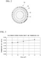
FIG. 2 is a detailed transverse cross sectional view of an optical fiber inFIG. 1 . -
FIG. 3 is a graph showing a relationship between packing density and transmission loss when a filling material is not provided. -
FIG. 4 is a graph used to derive an index C1. -
FIG. 5 is a graph used to derive an index C2. -
FIG. 6 is a graph used to derive an index C3. -
FIG. 7 is a graph used to derive an index C4. - As shown on
FIG. 1 , a present embodiment of anoptical fiber cable 10 is provided with acore 8 including a plurality ofoptical fibers 1a, afilling material 4, and asheath 5 that covers thecore 8. - In the present embodiment, a central axis of the
sheath 5 is referred to as central axis O, a direction along the central axis O is a longitudinal direction, and a cross-section that is orthogonal to the longitudinal direction is referred to as a transverse cross-section. An area of the transverse cross-section is referred to as a transverse cross-sectional area. Also, on a transverse cross sectional view, a direction that crosses the central axis O is referred to as a radial direction, and a direction that goes around the central axis O is referred to as a circumferential direction. - The
core 8 includes a plurality ofoptical fiber units 1 each including a plurality of theoptical fibers 1a, and awrapping tube 2 wrapping theoptical fiber units 1. The plurality of theoptical fiber units 1 may be twisted together in an SZ shape or a spiral shape, and are wrapped with thewrapping tube 2. The plurality of theoptical fibers 1a included in theoptical fiber unit 1 may be twisted together in an SZ shape or a spiral shape, or they may not be twisted together. Furthermore, thecore 8 may be configured of oneoptical fiber unit 1 being wrapped by thewrapping tube 2. - As the wrapping tube2, a non-woven fabric, polyester, or the like may be used. Also, as the
wrapping tube 2, a water absorbent tape that contributes to the water absorbability of the non-woven fabric, polyester, or the like may be used. In this case, it is possible to enhance the water absorption performance of theoptical fiber cable 10. Furthermore, thecore 8 may not include thewrapping tube 2, and theoptical fiber unit 1 may be in contact with thefilling material 4. In other words, thefilling material 4 may be used as thewrapping tube 2. However, when thewrapping tube 2 is included, because the falling apart of theoptical fiber unit 1 that occurs at the time of manufacturing is suppressed, it is possible to provide thecore 8 on the inside of thesheath 5 more easily. - The present embodiment of the
optical fiber unit 1 includes a plurality of theoptical fibers 1a, and abinding material 1b to bundle theoptical fibers 1a. An optical fiber core wire, an optical fiber, an optical fiber ribbon and the like may be used as theoptical fiber 1a. As one type of the optical fiber ribbon, the plurality of theoptical fibers 1a may constitute, in other words, an intermittently-fixed optical fiber ribbon. On the intermittently-fixed optical fiber ribbon, the plurality of theoptical fibers 1a, when pulled in a direction orthogonal to the direction to which they extend, are glued together so as to expand in a mesh like shape (spider web like shape). More specifically, a singleoptical fiber 1a is attached to adjacentoptical fibers 1a on both sides, on varying positions along the longitudinal direction with respect to theoptical fiber 1a. Also, the adjacentoptical fibers 1a are attached together in a regular interval on the longitudinal direction. - Furthermore, the aspect of the
optical fibers 1a included in thecore 8 is not limited to an intermittently-fixed optical fiber ribbon, and may be changed accordingly. - The
binding material 1b may be string like, sheet like, or tube like. Thebinding material 1b extends in the longitudinal direction, and is disposed to bundle a plurality of theoptical fibers 1a included in one of the optical fiber units. Also, a plurality of theoptical fibers 1a may be wrapped by thewrapping tube 2 as is (in other words, without constituting an optical fiber unit) without being bundled. - In other words, each of the
optical fiber units 1 may be formed by twisting together and bundling the plurality of theoptical fibers 1a. In this case, theoptical fiber unit 1 may not include thebinding material 1b. - Furthermore, as in
FIG. 1 and the like, a cross-sectional shape of theoptical fiber unit 1 is arranged. But due to the movement of theoptical fiber 1a inside of theoptical fiber unit 1, there are cases where the arrangement of the cross-sectional shape is changed. Also, as inFIG. 1 and the like, three of theoptical fiber units 1 form the inner layer, and seven of theoptical fiber units 1 form the outer layer. However, a portion of the outer layer may penetrate the inner layer. In other words, theoptical fiber unit 1 may not form these layers. - Also, in
FIG. 1 and the like, although a plurality of theoptical fiber unit 1 may be evenly placed with spaces in between, having no spaces in between, or having placement be uneven. Or the shape of thecore 8 may be arranged where thefilling material 4 is inserted in between theoptical fiber units 1. - As shown on
FIG. 2 , theoptical fiber 1a includes aglass portion 11, aprimary layer 12, asecondary layer 13 and acolored layer 14. - The
glass portion 11, for example, may be formed from silica glass that transmits light. Theprimary layer 12 may be formed from resin (UV curable resin for example), and covers theglass portion 11. Thesecondary layer 13 may be formed from resin (UV curable resin for example), and covers theprimary layer 12. Thecolored layer 14 may be formed from colored resin (UV curable resin for example) and is disposed on the outside of both theprimary layer 12 and thesecondary layer 13. - Furthermore, the
colored layer 14 may not be disposed. Also, coloring may be applied to thesecondary layer 13, so that thesecondary layer 13 itself is used as a colored layer. - Each of the
primary layer 12, thesecondary layer 13, and thecolored layer 14 may be formed from similar or differing specific materials. As an example, a UV curable resin, acrylate resin or the like may be used. - As shown on
FIG. 1 , tworip cords 7 and four tension members 6 are contained within thesheath 5. However, the quantity of therip cords 7 and the tension members 6 may be changed. Or, therip cords 7 and the tension members 6 may not be disposed. - For the
rip cord 7 used to tear off thesheath 5, a synthetic fiber such as polyester or the like may be used. Also, for therip cord 7, a rod made of a polypropylene (PP) or a nylon or the like may be used. For the material of the tension member 6, for example, a metallic wire (steel wire or the like) or an FRP (Fiber Reinforced Plastic) or the like may be used. - The
sheath 5 covers thecore 8. In other words, thesheath 5 contains a space to accommodate thecore 8. The accommodation space of the present embodiment is an entire region enclosed by an inner circumferential surface of thesheath 5. As for the material of thesheath 5, a polyolefin (PO) resin such as polyethylene (PE), polypropylene (PP), ethylene ether acrylate copolymer (EEA), ethylene vinyl acetate copolymer (EVA), ethylene propylene copolymer (EP), or polyvinyl chloride (PVC) may be used. Also, a compound (alloy, mixture) of the above resins may be used. - On the outer surface of the
sheath 5, a markingportion 5a indicating the position of therip cord 7 may be provided. As shown onFIG. 1 , the markingportion 5a may be a protrusion that sticks out on the outside in the radial direction, or a marking that is painted thereon, and the like. The markingportion 5a may not be disposed if for example, the position of therip cord 7 is identified via the bending direction of theoptical fiber cable 10 brought upon by the tension member 6. - The filling
material 4, on the inside portion of thesheath 5, is disposed so that it is in contact with theoptical fiber unit 1. For example, when thebinding material 1b is string like or when thebinding material 1b does not exist, the fillingmaterial 4 may be in direct contact with theoptical fiber 1a. Or, when thebinding material 1b is tubular, the fillingmaterial 4 may be in contact with thebinding material 1b while not contacting theoptical fiber 1a. In either case, by having the fillingmaterial 4 be in contact with theoptical fiber 1a, the fillingmaterial 4 acts as a cushion, suppressing micro-bends that may develop in theoptical fiber 1a. Also, frictional forces acting on theoptical fiber unit 1 may be adjusted via the fillingmaterial 4. Frictional forces may act on theoptical fiber 1a via the bindingmaterial 1b, or may act directly on theoptical fiber 1a. As an example of the fillingmaterial 4, if it is a material with cushioning properties, any material may be used. As a concrete example of the fillingmaterial 4, polyester fiber, aramid fiber, glass fiber and so on may be mentioned. Furthermore, the fillingmaterial 4 may be made up of yarn and the like, having water absorbability. In this case, it is possible to improve the water resistibility of theoptical fiber cable 10. - It is desirable to maximize the quantity of the
optical fibers 1a included in theoptical fiber cable 10, while decreasing transmission losses. In high packing density implementations of theoptical fibers 1a, lateral forces acting on theoptical fiber cable 10 easily cause micro-bends. In such cases, decreasing the packing density of theoptical fibers 1a (for example, making the space inside thesheath 5 larger) may be thought of. But, simply decreasing the packing density of theoptical fibers 1a, the frictional forces acting on theoptical fiber 1a decrease, making the incidence of untwisting in theoptical fibers 1a easier. When untwisting occurs, a shortage in the extra length rate of theoptical fibers 1a inside theoptical fiber cable 10 occurs, and the elongation strain of theoptical fibers 1a that occurs is connected to an increase in optical losses. Also, when frictional forces acting on theoptical fibers 1a are too small, theoptical fiber 1a on the end portion in the longitudinal direction of theoptical fiber cable 10 protrudes out from thesheath 5, exceeding the allowable range. - Furthermore, the frictional forces acting on the
optical fiber 1a are the frictional forces that develop between theoptical fiber 1a and the elements in touch with theoptical fiber 1a. For example, the frictional forces may develop between the adjacentoptical fibers 1a, or between theoptical fiber 1a and other materials in touch with theoptical fiber 1a. - According to
non-patent literatures 1 to 3 below, losses due to micro-bends tend to be affected by both the geometry (structure) of theoptical fiber 1a and the optical properties. - Non-Patent Literature 1: J. Baldauf, et al., "Relationship of Mechanical Characteristics of Dual Coated Single Mode Optical Fibers and Microbending Loss," IEICE Trans. Commun., vol. E76-B, No. 4, 1993.
- Non-Patent Literature 2: K. Petermann, et al., "Upper and Lower Limits for the Microbending Loss in Arbitrary Single-Mode Fibers," J. Lightwave technology, vol. LT-4, no. 1, pp. 2-7, 1986.
- Non-Patent Literature 3: P. Sillard, et al., "Micro-Bend Losses of Trench-Assisted Single-Mode Fibers," ECOC2010, We.8.F.3, 2010.
- According to
non-patent literatures 1 to 3 mentioned above, it is possible to express the effect that the geometry of theoptical fiber 1a has on micro-bend losses as the geometric loss factor FµBL_G obtained from equation (1) shown below. Definitions of each parameter used in equation (1) are as follows: - Hf: bending stiffness of the
glass portion 11 of theoptical fiber 1a (Pa m4) - D0: deformation resistance of the secondary layer 13 (Pa)
- H0: bending stiffness of the secondary layer 13 (Pa m4)
- µ: predetermined constant
- EP: young's modulus of the primary layer 12 (MPa)
- df: outer diameter of the glass portion 11 (µm)
- tP: thickness of the primary layer 12 (µm)
- Eg: young's modulus of the glass portion 11 (GPa)
- RS: radius of the outer periphery surface of the secondary layer 13 (µm)
- tS: thickness of the secondary layer 13 (µm)
- ES: young's modulus of the secondary layer 13 (MPa)
- RP: radius of the outer periphery of the primary layer 12 (µm)
Furthermore, tP = RP- df / 2, and tS = RS - RP. - Referring to
non-patent literatures 1 to 3 mentioned above, it is possible to express the effect that the optical properties of theoptical fiber 1a has on micro-bend losses as the optical properties loss factor FµBL_△β obtained from equation (2) shown below. Definitions of each parameter used in equation (2) are as follows: - △β: the difference between the propagation constant in a waveguide mode of transmitted light that propagates in the
optical fiber 1a, and the propagation constant of the radiation mode. Units are (rad/m). The "radiation mode" is a higher order mode with respect to the possible propagation waveguide mode of theoptical fiber 1a. - p: predetermined constant.
[Equation 2]
- According to
non-patent literature 4 below, a typical value of constant µ in equation (1) is 3. As such, equation (1) becomes equation (3) shown below. Non-Patent Literature 4: K. Kobayashi, et al., "Study of Microbending loss in thin coated fibers and fiber ribbons," IWCS, pp.386-392, 1993.
[Equation 3]
- According to the above-mentioned
non-patent literature 2, andnon-patent literature 5 below, a typical value of constant p in equation (2) is 4. As such, equation (2) becomes equation (4) shown below. - Non-Patent Literature 5: C. D. Hussey, et al., "Characterization and design of single-mode optical fibres," Optical and Quantum Electronics, vol. 14, no. 4, pp. 347-358, 1982.
[Equation 4]
- As in equation (4), the value of the optical properties loss factor FµBL_△β is the eighth exponent of the inverse proportion of the constant of difference in propagation △β. From equations (3) and (4), it is understood that the larger the values of the derived geometric loss factor FµBL_G and the optical properties loss factor FµBL_△β become, the larger the micro-bend losses of the
optical fibers 1a become. - Here, the △β of a typical optical fiber (for example, ITU-T G.657.A1 compliant) ranges from 9,900 to 12,000 (rad/m). As opposed to this, low loss optical fibers for long haul transmission (for example, ITU-T G.654.E compliant) have a △β value in the range of 9,000 to 10,000 (rad/m). In such low loss optical fibers, because the value of △β is small, the optical properties loss factor FµBL_△β becomes large, and it is observed that micro-bend losses form easily.
- In the
optical fiber cable 10, the higher the packing density of theoptical fibers 1a in the accommodation space, the easier it is for micro-bend losses to form. The reason is that, when theoptical fiber cable 10 is bent for example, theoptical fibers 1a are strongly pressed by the otheroptical fibers 1a, the wrappingtube 2, or thesheath 5, and minute bends (micro-bends) in theoptical fibers 1a easily form. If the fillingmaterial 4 is accordingly disposed in the surroundings of theoptical fibers 1a, the fillingmaterial 4 acts as a cushion, decreasing the micro-bends and the micro-bend losses. On the other hand, if theoptical fiber cable 10 is stuffed with too much of the fillingmaterial 4, the cushioning ability of the fillingmaterial 4 declines, so that it cannot effectively decrease the micro-bends and the micro-bend losses. - Therefore, to decrease micro-bend losses, not only does the packing density of the
optical fibers 1a need to be considered, but setting the appropriate substantial density of the stuffing amount of the fillingmaterial 4 is also required. In addition, as mentioned earlier, other than the stuffing amount of the fillingmaterial 4, the micro-bend losses are affected by the geometrical effects, as well as the value of △β. - With that, after earnest consideration, the inventors of the present invention have quantified the effects the various parameters of the
optical fiber cable 10 have on micro-bend losses, and have discovered conditions where it is possible to render the micro-bend losses constantly below a certain level. Details are explained using Table 1 and Table 2 below.


- As shown on Table 1 and Table 2, samples 1-1 to 1-22 of the
optical fiber cable 10 are made. In each sample, as theoptical fiber 1a, an intermittently-fixed optical fiber ribbon that has been twisted together is used. In Table 1 and Table 2, D1 is theoptical fiber 1a packing density (units: pcs/mm2), and is defined by equation (5) below. Definitions of each parameter used in equation (5) are as follows: - N: The quantity of the
optical fibers 1a packed in the accommodation space in the sheath 5 (pcs) - S: The transverse cross-sectional area of the accommodation space in the sheath 5 (mm2)
- A: The sum of the transverse cross-sectional areas of the material (excluding
optical fibers 1a) disposed in the accommodation space of the sheath 5 (mm2). - The value of A in the example of
FIG. 1 is the sum of the transverse cross-sectional areas of the wrappingtube 2, the bindingmaterial 1b and the fillingmaterial 4. The value of S in the example ofFIG. 1 is the transverse cross-sectional area of the region enclosed by the inner circumferential surface of thesheath 5.
[Equation 5]
- On Table 1 and Table 2, D2 is the packing density (units: d/mm2) of the filling
material 4, and is defined by equation (6) below. In equation (6), T is the gross denier value (units: denier) of the fillingmaterial 4 in the accommodation space.
[Equation 6]
- On Table 1 and Table 2, C1 is a coefficient that expresses the effects of the packing density D2 of the filling
material 4 on the micro-bend losses. C2 is a coefficient that expresses the effects of △β of theoptical fibers 1a on the micro-bend losses. C3 is a coefficient that expresses the effects of the geometric loss factor on the micro-bend losses. C4 is a coefficient that expresses the effects of the cushioning ability of the fillingmaterial 4 on the micro-bend losses. - Below, the above-mentioned coefficients C1 to C4 are explained.
- First, findings in the case where the filling
material 4 is not provided, regarding the relationship of the packing density of theoptical fibers 1a and the transmission losses are explained. As shown on Table 3, fouroptical fiber cables 10 are made. The conditions of each of the samples 1-4, 1-5, and 1-6 are the same as those for each sample shown on Table 1 and Table 2. As for sample 1-5', except for an increase in the quantity of theoptical fibers 1a as compared to sample 1-5, all other conditions are the same as sample 1-5. OnFIG. 3 which is based off of Table 3, under the condition that the fillingmaterial 4 is not provided, the value of the transmission loss is substantially proportional to that of the value of D1. FromFIG. 3 , it is possible to express the relationship between D1 and the transmission loss as the equation y = 0.0144x+0.0713 (hereupon referred to as the "conversion formula").[Table 3] Sample No. D1[pcs/mm2] Transmission [dB/km] Loss 1-4 9 0.205 1-5 10 0.210 1-5' 11 0.228 1-6 13 0.260 - The coefficient C1 is derived from the shown below Table 4 and
FIG. 4 . As shown on Table 4, samples 3-1 to 3-6 of theoptical fiber cable 10 are made. In sample 3-1, no fillingmaterial 4 is provided, and the packing density D1 of theoptical fibers 1a is 10.6 (pcs/mm2). In samples 3-2 to 3-6, the quantity of theoptical fibers 1a (N) and the sum of the accommodation space transverse cross-sectional areas of the sheath 5 (S) are the same as those of sample 3-1, except that the fillingmaterial 4 is stuffed. Also, the amount of stuffing of the fillingmaterial 4 in samples 3-2 to 3-6 is different from each other. For this reason, the packing density D2 of the fillingmaterial 4 differs for each of the samples 3-1 to 3-6. As shown on Table 4, the transmission loss of each of the samples 3-1 to 3-6 has been measured.[Table 4] Sample No. D2[d/mm2] Transmission [dB/km] Loss D1' [pcs/mm2] Relative Ratio 3-1 0 0.224 10.6 1.00 3-2 200 0.220 10.3 0.97 3-3 300 0.215 10 0.94 3-4 500 0.208 9.5 0.90 3-5 1500 0.230 11 1.04 3-6 2000 0. 287 15 1.42 - On table 4, [D1'] is the value of the apparent packing density of the
optical fibers 1a obtained from plugging in the measured result of the transmission loss into the conversion formula previously mentioned. Regarding sample 3-1, because D2 = 0, in other words, the condition is that no fillingmaterial 4 is to be provided, the value of D1 (the actualoptical fiber 1a packing density), and the value of D1' (value of the apparent packing density taking into account the effect of the filling material 4) become equal. On the other hand, if for example the transmission loss of sample 3-2 (0.220dB/km) were to be substituted as y in the conversion formula mentioned earlier, the value of x would be 10.3. Thus, the values of x obtained as such are what become the values of the apparent packing density D1' of theoptical fiber 1a. - The [Relative Ratio] shown on Table 4 is ratio of the values of each of the samples 3-1 to 3-6 against the value of D1' of sample 3-1 (10.6). For example, because D1' = 9.5 for sample 3-4, the relative ratio is 9.5-10.6 = 0.90.
- The horizontal axis of
FIG. 4 is D2 of Table 4, while the vertical axis ofFIG. 4 is the [Relative Ratio] of Table 4. The graph onFIG. 4 is approximated using y = 3.17×10-7x2-4.50×10⁻⁴x+1.03. Setting the coefficient C1 to the value of y in this approximation equation, and D2 to be the value of x, equation (7) below is obtained. The coefficient C1 derived from equation (7) is a quantified value of the effect that the packing density D2 of the fillingmaterial 4 has on the micro-bends.
[Equation 7]
- The coefficient C2 is derived from the below Table 5 and
FIG. 5 . As shown on Table 5, samples 4-1 to 4-7 of theoptical fiber cable 10 are made. The values of △β of each of the samples 4-1 to 4-7 differ. In the column [△β-8], the negative eighth exponent of △β of each sample is shown. Using the value of the negative eighth exponent of △β is based off of equation (4) mentioned earlier. The column [D"] on Table 5 shows the upper limit of the packing density of theoptical fibers 1a so that the value of transmission loss is equal to or less than 0.23dB/km for each sample. The [Relative Ratio] column shows a ratio where a typical value of the packing density of theoptical fibers 1a of the optical fiber cables, [11pcs/mm2] is set as the standard.[Table 5] Sample No. Δ β [rad/m] -2p Δ β -8 D1"[pcs/mm2] Relative Ratio 4-1 9350 -8 1.71 × 10⁻³² 5.5 2.00 4-2 9400 -8 1.64 × 10⁻³² 6.2 1.77 4-3 9900 -8 1.08 × 10⁻³² 11 1.00 4-4 10000 -8 1.00 × 10⁻³² 11 1.00 4-5 10800 -8 5.40 × 10⁻³³ 12 0.92 4-6 11000 -8 4.67 × 10⁻³³ 11.3 0.97 4-7 11500 -8 3.27 × 10⁻³³ 13 0.85 - The horizontal axis of
FIG. 5 is [△β-8] of Table 5, while the vertical axis is the [Relative Ratio] of Table 5. As with the derivation process for the coefficient C1, when the value of the coefficient C2 is set as the value of y in the approximation equation, and △β-8 to be the value of x, equation (8) below is obtained. The coefficient C2 derived from equation (8) is to convert a value of △β to the apparent packing density of theoptical fibers 1a.
[Equation 8]
- The coefficient C3 is derived from the below Table 6 and
FIG. 6 . As shown on Table 6, samples 5-1 to 5-5 of theoptical fiber cable 10 are made. In each of the samples 5-1 to 5-5, the value of △β, 9,350 (rad/m), is shared among the samples, however the design of theprimary layer 12 and thesecondary layer 13 differs, causing the values of the geometric loss factor FµBL_G to differ. D1" on Table 6 has the same meaning as it does on Table 5. Column [Relative Ratio] shows the ratio where the smallest amount of the value of the geometric loss factor FµBL_G (in other words, where micro-bends are least likely to form) of sample 5-5 is set as the standard.[Table 6] Sample No. F µ BL_G D1" [pcs/mm2] Relative Ratio 5-1 6.78 × 1026 5.5 1.82 5-2 4.99 × 1026 6. 5 1. 54 5-3 3.51 × 1026 7.5 1. 33 5-4 5.51 × 1025 10 1.00 5-5 5.47 × 1025 10 1.00 - The horizontal axis of
FIG. 6 is [FµBL_G] of Table 6, while the vertical axis ofFIG. 6 is the [Relative Ratio] of Table 6. As with the derivation process for the coefficient C1, when the value of the coefficient C3 is set as the value of y in the approximation equation of the graph onFIG. 6 , and FµBL_G is set as the value of x, equation (9) below is obtained. The coefficient C3 derived from equation (9) is to convert a value of FµBL_G to the apparent packing density of theoptical fibers 1a.
[Equation 9]
- The coefficient C4 is derived from the below Table 7 and
FIG. 7 . As shown on Table 7, samples 6-1 to 6-6 of theoptical fiber cable 10 are made. Although in each of the samples 6-1 to 6-6, the stuffing amount of the fillingmaterial 4 differs, the value of the packing density D1 of theoptical fibers 1a is designed to be similar. When D1 is similar, as the amount of stuffing of the fillingmaterial 4 becomes larger, the cushioning ability increases, and the transmission loss decreases. As with the derivation process of the coefficient C1, the transmission loss of each of the samples is measured, and using the previously mentioned conversion equation, the apparent packing density D1' of theoptical fibers 1a is derived. Column [Relative Ratio] shows the ratio of the value of D1', where the standard is sample 6-1 that is not stuffed with the fillingmaterial 4.[Table 7] Sample No. D2[d/mm2] D1 [pcs/mm2] Transmission [dB/km] Loss D1' [pcs/mm2] Relative Ratio 6-1 0 10 0.215 10 1 6-2 200 10 0.211 9.7 0.97 6-3 300 10 0.210 9.6 0.96 6-4 500 10 0.205 9.3 0.93 6-5 1500 10 0.195 8.6 0.86 6-6 2000 10 0.189 8.2 0. $2 - The horizontal axis of
FIG. 7 is [D2] of Table 7, while the vertical axis ofFIG. 7 is the [Relative Ratio] of Table 7. As with the derivation process for the coefficient C1, when the value of the coefficient C4 is set as the value of y in the approximation equation of the graph onFIG. 7 , and D2 is set as the value of x, equation (10) below is obtained. The coefficient C4 derived from equation (10) is to convert a value of the cushioning ability of the fillingmaterial 4 to the apparent packing density of theoptical fibers 1a.
[Equation 10]
- On Table 1 and Table 2, the column [D1×C1×C2×C3×C4] shows the previously mentioned actual packing density D1 of the actual
optical fiber 1a, multiplied by each of the coefficients C1 to C4. This value is referred to as the [Index Q] throughout the present description (refer to equation (11) below).
[Equation 11]
- On the column [Optical Losses] of Table 1 and Table 2, the measurement results of the transmission losses at the measured wave length 1.55µm are shown.
- On Table 1 and Table 2, on the column [Fiber Pulling Force], the measured results of the pulling force (referred to as the "fiber pulling force" below) applied when pulling the
optical fibers 1a from each sample of the optical fiber cables (length 10m) are shown. When the fiber pulling force is equal to or greater than 15N/10m, the frictional forces acting on theoptical fibers 1a is sufficient, suppressing the protrusion of theoptical fibers 1a from thesheath 5 as theoptical fibers 1a exceed the allowable range on an end in the longitudinal direction of the optical fiber cable for example. - Regarding samples 1-1, 1-4, 1-5, 1-11, 1-12, 1-13, 1-14, 1-17, 1-18, 1-19 and 1-22, the value of the optical losses is less than 0.23dB/km, while the fiber pulling force is equal to or greater than 15N/10m. For this reason, in these samples, on the [Judgment] column, where the performance was good, OK is shown. A common point that is mentioned between samples with an OK judgment is that, the value of the index Q is less than 20, and the fiber pulling force is equal to or greater than 15N/10m. Thus, it is understood that by fulfilling these requirements, it is possible to obtain an
optical fiber cable 10 which the magnitude of micro-bend losses is that which can be tolerated in actual use, taking into account the amount of the fillingmaterial 4, the geometric and the optical properties (△β) of theoptical fiber 1a and so on, along with the adequate frictional forces acting on theoptical fiber 1a. - Based on the above, the
optical fiber cable 10 that the inventors of the present invention are proposing, includes thesheath 5, and thecore 8 containing a plurality of theoptical fibers 1a in a state where theoptical fibers 1a are twisted together and packed within the accommodation space in thesheath 5, in which each of the plurality of theoptical fibers 1a contains theglass portion 11, theprimary layer 12 that covers theglass portion 11, and thesecondary layer 13 that covers theprimary layer 12, and a value of the index Q is less than 20, and a fiber pulling force when pulling out theoptical fiber 1a is equal to or greater than 15N/10m. In this manner, theoptical fiber cable 10 where the frictional forces acting on theoptical fibers 1a is maintained, while having good light transmission characteristics during actual use conditions is provided. - Furthermore, in either case where the filling
material 4 is not provided (for example sample 1-1) or the fillingmaterial 4 is provided (for example sample 1-11), it is possible to fulfill the conditions where the index Q is less than 20, and the fiber pulling force is equal to or greater than 15N/10m. Therefore, the fillingmaterial 4 may or may not be disposed on the inner part of thesheath 5. - Furthermore, the technical scope of the present invention is not limited to any of the previously mentioned embodiments, and various modifications can be made without departing from a spirit of the present invention.
- For example, in the embodiments, although the case of the
optical fibers 1a being the intermittently-fixed optical fiber ribbon is explained, it can be understood that in a case where a plurality of singleoptical fibers 1a are bundled and twisted together, where the value of the index Q is less than 20, and the fiber pulling force is equal to or greater than 15N/10m, similar effects can be obtained. - Also, the wrapping
tube 2 may not be provided. In this case, the sum of cross-sectional areas of the wrappingtube 2 is not included in the value of A in equation (5). - Also, in the
optical fiber cable 10 of the previously mentioned embodiment, the entire region surrounded by the inner circumferential surface of thesheath 5 was designated as the accommodation area. However, the explained conditions of the previously mentioned embodiments are also applicable to slot-type cables or loose tube cables. For a slot-type cable, thecore 8 includes a slot element where a plurality of grooves (slots) are formed, and theoptical fibers 1a in a state where theoptical fibers 1a have been twisted together are packed in the accommodation space of the grooves. Therefore, the inner side of the grooves formed in the slot element is the accommodation space, and N of equation (5) is the quantity of theoptical fibers 1a that are packed in the accommodation space of the grooves, S is the sum of the transverse cross-sectional areas of the inner side of the grooves. In the case of the loose tube cable, in thecore 8, a plurality of the loose tubes are included, each of the loose tubes having theoptical fibers 1a in a state where theoptical fibers 1a are twisted together and packed in the loose tubes. Therefore, the inner side of the loose tubes is the accommodation space, N of equation (5) is the quantity of theoptical fibers 1a that are packed in the loose tubes, S is the sum of the transverse cross-sectional areas of the inner side of the loose tubes. - Otherwise, where the objective of the technical scope of the present invention is not departed from, where it is possible and appropriate, the components of the previously mentioned present invention may be substituted for well-known components. Also, modifications of the previously mentioned embodiments may be appropriately combined.
-
- 1a
- Optical Fibers
- 2
- Wrapping Tube
- 4
- Filling Material
- 5
- Sheath
- 8
- Core
- 10
- Optical Fiber Cable
[Equation 1]

Claims (2)
- An optical fiber cable comprising:a sheath; anda core including a plurality of optical fibers in a state where the optical fibers are twisted together and are packed in an accommodation space in the sheath;wherein the plurality of optical fibers each contains a glass portion, a primary layer that covers the glass portion, and a secondary layer that covers the primary layer,a value of an index Q defined by the following Equations (3), (5), (6), (7), (8), (9), (10) and (11) is less than 20, anda fiber pulling force when pulling out the optical fibers is equal to or greater 15 N/10m,
[Equation 3]





 where EP [MPa] is Young modulus of the primary layer 12,df [µm] is an outer diameter of the glass portion,Eg [GPa] is Young's modulus of the glass portion,RS [µm] is a radius of an outer periphery of the secondary layer,ts [µm] is a thickness of the secondary layer,ES [MPa] is Young's modulus of the secondary layer,RP [µm] is a radius of outer periphery of the primary layer,N [pcs] is a quantity of the optical fibers packed in the accommodation space,S [mm2] is a transverse cross-sectional area of the accommodation space,A [mm2] is a sum of transverse cross-sectional areas of elements, with the exception of the optical fibers, disposed in the accommodation space,T [d] is a total denier of filling material when the filling material is disposed in the accommodation space, and△β (rad/m) is a difference between a propagation constant in a waveguide mode of transmitted light that propagates in the optical fibers, and a propagation constant of a radiation mode.
 - An optical fiber cable according to claim 1,
wherein the filling material is disposed in the accommodation space.
Applications Claiming Priority (2)
| Application Number | Priority Date | Filing Date | Title |
|---|---|---|---|
| JP2020147729 | 2020-09-02 | ||
| PCT/JP2021/031193 WO2022050152A1 (en) | 2020-09-02 | 2021-08-25 | Optical fiber cable |
Publications (1)
| Publication Number | Publication Date |
|---|---|
| EP4209813A1 true EP4209813A1 (en) | 2023-07-12 |
Family
ID=80490931
Family Applications (1)
| Application Number | Title | Priority Date | Filing Date |
|---|---|---|---|
| EP21864210.6A Withdrawn EP4209813A1 (en) | 2020-09-02 | 2021-08-25 | Optical fiber cable |
Country Status (8)
| Country | Link |
|---|---|
| US (1) | US20230273381A1 (en) |
| EP (1) | EP4209813A1 (en) |
| JP (1) | JPWO2022050152A1 (en) |
| CN (1) | CN115698808A (en) |
| AU (1) | AU2021335442A1 (en) |
| CA (1) | CA3187252A1 (en) |
| TW (1) | TWI779807B (en) |
| WO (1) | WO2022050152A1 (en) |
Families Citing this family (4)
| Publication number | Priority date | Publication date | Assignee | Title |
|---|---|---|---|---|
| EP4427083A4 (en) * | 2021-11-05 | 2025-10-08 | Corning Res & Dev Corp | High fiber density optical fiber cable |
| US20240353639A1 (en) * | 2021-12-10 | 2024-10-24 | Sumitomo Electric Industries, Ltd. | Optical fiber cable and method for manufacturing optical fiber cable |
| JP2024086151A (en) * | 2022-12-16 | 2024-06-27 | 住友電気工業株式会社 | Fiber optic cable |
| WO2025263539A1 (en) * | 2024-06-21 | 2025-12-26 | 住友電気工業株式会社 | Optical fiber cable |
Family Cites Families (12)
| Publication number | Priority date | Publication date | Assignee | Title |
|---|---|---|---|---|
| JP3462770B2 (en) * | 1998-10-28 | 2003-11-05 | 住友電気工業株式会社 | Fiber optic cable |
| KR100526506B1 (en) * | 2003-05-27 | 2005-11-08 | 삼성전자주식회사 | Optical cable for air blow installation |
| US7050688B2 (en) * | 2003-07-18 | 2006-05-23 | Corning Cable Systems Llc | Fiber optic articles, assemblies, and cables having optical waveguides |
| JP2010217392A (en) * | 2009-03-16 | 2010-09-30 | Fujikura Ltd | Optical fiber cable |
| US8989543B2 (en) * | 2011-11-17 | 2015-03-24 | Sumitomo Electric Industries, Ltd. | Optical cable |
| JP6150422B2 (en) | 2013-01-21 | 2017-06-21 | 株式会社フジクラ | Fiber optic cable |
| US10458191B2 (en) * | 2013-12-28 | 2019-10-29 | Trican Well Service, Ltd. | Carbon fiber based tubing encapsulated cable |
| JP6273847B2 (en) * | 2014-01-09 | 2018-02-07 | 住友電気工業株式会社 | Optical fiber and optical cable |
| US10578796B2 (en) * | 2016-04-01 | 2020-03-03 | Fujikura Ltd. | Optical fiber and method for manufacturing same |
| JP6611766B2 (en) * | 2017-08-09 | 2019-11-27 | 株式会社フジクラ | Manufacturing method of optical fiber and optical fiber |
| JP7401728B2 (en) | 2019-03-15 | 2023-12-20 | 横浜ゴム株式会社 | Rubber composition for semi-continuous marine hose and semi-continuous marine hose |
| TWM594154U (en) * | 2019-09-18 | 2020-04-21 | 光元先進科技股份有限公司 | Enhanced optical fiber cable |
-
2021
- 2021-08-25 AU AU2021335442A patent/AU2021335442A1/en not_active Abandoned
- 2021-08-25 WO PCT/JP2021/031193 patent/WO2022050152A1/en not_active Ceased
- 2021-08-25 CN CN202180043054.4A patent/CN115698808A/en active Pending
- 2021-08-25 US US18/016,115 patent/US20230273381A1/en not_active Abandoned
- 2021-08-25 EP EP21864210.6A patent/EP4209813A1/en not_active Withdrawn
- 2021-08-25 CA CA3187252A patent/CA3187252A1/en active Pending
- 2021-08-25 JP JP2022546267A patent/JPWO2022050152A1/ja active Pending
- 2021-08-30 TW TW110132111A patent/TWI779807B/en not_active IP Right Cessation
Also Published As
| Publication number | Publication date |
|---|---|
| AU2021335442A1 (en) | 2023-02-23 |
| TW202227868A (en) | 2022-07-16 |
| CN115698808A (en) | 2023-02-03 |
| CA3187252A1 (en) | 2022-03-10 |
| TWI779807B (en) | 2022-10-01 |
| WO2022050152A1 (en) | 2022-03-10 |
| JPWO2022050152A1 (en) | 2022-03-10 |
| US20230273381A1 (en) | 2023-08-31 |
Similar Documents
| Publication | Publication Date | Title |
|---|---|---|
| EP4209813A1 (en) | Optical fiber cable | |
| EP1573377B1 (en) | Optical tube assembly having a dry insert and methods of making the same | |
| US6785450B2 (en) | Self-supporting fiber optic cable | |
| US7254303B2 (en) | Optical tube assembly having a dry insert and methods of making the same | |
| US7747117B2 (en) | Optical tube assembly having a dry insert and methods of making the same | |
| US7050688B2 (en) | Fiber optic articles, assemblies, and cables having optical waveguides | |
| EP2761350B1 (en) | Fiber optic ribbon cable having enhanced ribbon stack coupling | |
| US5517591A (en) | Compact slotted core ribbon cable | |
| US20030206705A1 (en) | Fiber optic cable with hight strength component | |
| US20110211794A1 (en) | Bend-insensitive optical cable | |
| US6621965B2 (en) | Optical fiber cable with controlled helix-plus-EFL values and methods therefor | |
| US20040223707A1 (en) | Optical tube assembly having a dry insert and methods of making the same | |
| EP1550891A2 (en) | Improved optical fiber cables | |
| US20150268429A1 (en) | Coupling system for fiber optic cable using raised tape |
Legal Events
| Date | Code | Title | Description |
|---|---|---|---|
| STAA | Information on the status of an ep patent application or granted ep patent |
Free format text: STATUS: THE INTERNATIONAL PUBLICATION HAS BEEN MADE |
|
| PUAI | Public reference made under article 153(3) epc to a published international application that has entered the european phase |
Free format text: ORIGINAL CODE: 0009012 |
|
| STAA | Information on the status of an ep patent application or granted ep patent |
Free format text: STATUS: REQUEST FOR EXAMINATION WAS MADE |
|
| 17P | Request for examination filed |
Effective date: 20221222 |
|
| AK | Designated contracting states |
Kind code of ref document: A1 Designated state(s): AL AT BE BG CH CY CZ DE DK EE ES FI FR GB GR HR HU IE IS IT LI LT LU LV MC MK MT NL NO PL PT RO RS SE SI SK SM TR |
|
| DAV | Request for validation of the european patent (deleted) | ||
| DAX | Request for extension of the european patent (deleted) | ||
| STAA | Information on the status of an ep patent application or granted ep patent |
Free format text: STATUS: THE APPLICATION HAS BEEN WITHDRAWN |
|
| 18W | Application withdrawn |
Effective date: 20240426 |