EP4209779A1 - Systems and methods for detecting anomalies in objects - Google Patents
Systems and methods for detecting anomalies in objects Download PDFInfo
- Publication number
- EP4209779A1 EP4209779A1 EP22202310.3A EP22202310A EP4209779A1 EP 4209779 A1 EP4209779 A1 EP 4209779A1 EP 22202310 A EP22202310 A EP 22202310A EP 4209779 A1 EP4209779 A1 EP 4209779A1
- Authority
- EP
- European Patent Office
- Prior art keywords
- light
- transmission element
- light transmission
- couplant
- anomaly
- Prior art date
- Legal status (The legal status is an assumption and is not a legal conclusion. Google has not performed a legal analysis and makes no representation as to the accuracy of the status listed.)
- Pending
Links
Images






Classifications
-
- G—PHYSICS
- G01—MEASURING; TESTING
- G01N—INVESTIGATING OR ANALYSING MATERIALS BY DETERMINING THEIR CHEMICAL OR PHYSICAL PROPERTIES
- G01N21/00—Investigating or analysing materials by the use of optical means, i.e. using sub-millimetre waves, infrared, visible or ultraviolet light
- G01N21/84—Systems specially adapted for particular applications
- G01N21/88—Investigating the presence of flaws or contamination
- G01N21/95—Investigating the presence of flaws or contamination characterised by the material or shape of the object to be examined
-
- G—PHYSICS
- G01—MEASURING; TESTING
- G01N—INVESTIGATING OR ANALYSING MATERIALS BY DETERMINING THEIR CHEMICAL OR PHYSICAL PROPERTIES
- G01N21/00—Investigating or analysing materials by the use of optical means, i.e. using sub-millimetre waves, infrared, visible or ultraviolet light
- G01N21/84—Systems specially adapted for particular applications
- G01N21/88—Investigating the presence of flaws or contamination
- G01N21/95—Investigating the presence of flaws or contamination characterised by the material or shape of the object to be examined
- G01N21/958—Inspecting transparent materials or objects, e.g. windscreens
-
- B—PERFORMING OPERATIONS; TRANSPORTING
- B64—AIRCRAFT; AVIATION; COSMONAUTICS
- B64C—AEROPLANES; HELICOPTERS
- B64C39/00—Aircraft not otherwise provided for
- B64C39/02—Aircraft not otherwise provided for characterised by special use
- B64C39/024—Aircraft not otherwise provided for characterised by special use of the remote controlled vehicle type, i.e. RPV
-
- G—PHYSICS
- G01—MEASURING; TESTING
- G01N—INVESTIGATING OR ANALYSING MATERIALS BY DETERMINING THEIR CHEMICAL OR PHYSICAL PROPERTIES
- G01N21/00—Investigating or analysing materials by the use of optical means, i.e. using sub-millimetre waves, infrared, visible or ultraviolet light
- G01N21/01—Arrangements or apparatus for facilitating the optical investigation
-
- G—PHYSICS
- G02—OPTICS
- G02B—OPTICAL ELEMENTS, SYSTEMS OR APPARATUS
- G02B1/00—Optical elements characterised by the material of which they are made; Optical coatings for optical elements
- G02B1/10—Optical coatings produced by application to, or surface treatment of, optical elements
-
- B—PERFORMING OPERATIONS; TRANSPORTING
- B64—AIRCRAFT; AVIATION; COSMONAUTICS
- B64U—UNMANNED AERIAL VEHICLES [UAV]; EQUIPMENT THEREFOR
- B64U2101/00—UAVs specially adapted for particular uses or applications
- B64U2101/30—UAVs specially adapted for particular uses or applications for imaging, photography or videography
-
- G—PHYSICS
- G01—MEASURING; TESTING
- G01N—INVESTIGATING OR ANALYSING MATERIALS BY DETERMINING THEIR CHEMICAL OR PHYSICAL PROPERTIES
- G01N21/00—Investigating or analysing materials by the use of optical means, i.e. using sub-millimetre waves, infrared, visible or ultraviolet light
- G01N21/01—Arrangements or apparatus for facilitating the optical investigation
- G01N2021/0106—General arrangement of respective parts
- G01N2021/0112—Apparatus in one mechanical, optical or electronic block
-
- G—PHYSICS
- G01—MEASURING; TESTING
- G01N—INVESTIGATING OR ANALYSING MATERIALS BY DETERMINING THEIR CHEMICAL OR PHYSICAL PROPERTIES
- G01N2201/00—Features of devices classified in G01N21/00
- G01N2201/02—Mechanical
- G01N2201/021—Special mounting in general
- G01N2201/0214—Airborne
Definitions
- Examples of the subject disclosure generally relate to systems and methods for detecting anomalies, such as cracks, scratches, nicks, chips, grooves, cuts, or the like, in objects, such as windows.
- Windows, windshields, and other transparent or translucent objects may be susceptible to anomalies.
- a foreign object may impact such objects, thereby causing an anomaly such as a crack, scratch, nick, chip, pit, gouge, groove, divot, or the like to form.
- an anomaly such as a crack, scratch, nick, chip, pit, gouge, groove, divot, or the like to form.
- an anomaly may not be readily visible to an individual.
- Various vehicles include windows.
- commercial aircraft include fuselages including numerous windows.
- individuals such as mechanics or inspectors utilize a lift to visually examine the windows for scratches.
- scratches and cracks within the windows can compromise the integrity of the windows, and can be difficult to see with the naked eye.
- a transparent or translucent structure for example, a window, windshield, or the like, which can be part of a vehicle.
- certain examples of the subject disclosure provide a system for detecting an anomaly of an object (for example, a transparent object, such as a window).
- the system includes a light source configured to emit light, a light transmission element having a textured surface, and an optical couplant configured to be disposed between the light transmission element and the object. At least a portion of the light emitted by the light source is configured to pass into the light transmission element through the textured surface and pass into the object through the optical couplant. At least a portion of the light that passes into the object internally reflects within the object and impinges on the anomaly to provide an illumination that indicates the location of the anomaly.
- the object is a window of a vehicle.
- the textured surface is formed on a first surface of the light transmission element.
- the first surface is opposite from a second surface that is smooth.
- the first surface is between the light source and the second surface.
- the textured surface includes a plurality of variances.
- the second surface is devoid of variances.
- the optical couplant comprises water.
- the light source is configured to emit the light onto the light transmission element at an acute angle.
- an imaging device is configured to acquire one or more images of the object as the light source emits the light onto the light transmission element.
- a couplant applicator is configured to apply the optical couplant between the light transmission element and the object.
- a control unit is in communication with the light source (and optionally other components).
- the control unit is configured to control operation of the light source (and optionally the other components).
- the system further includes a support frame.
- the light source and the light transmission element are coupled to the support frame.
- the system also includes a base having a plurality of wheels. The base is coupled to the support frame.
- a rotator is coupled to the support frame.
- the rotator is configured to rotate the system between different orientations.
- a handle coupled to the support frame.
- an unmanned aerial vehicle (UAV) is coupled to the support frame.
- UAV unmanned aerial vehicle
- one or more articulating arms are coupled to the support frame.
- a mobile base is coupled to the one or more articulating arms.
- a couplant distributor is configured to apply the optical couplant between the light transmission element and the object.
- the couplant distributor includes an outer ring having a plurality of fluid outlets in fluid communication with an internal fluid passage.
- Certain examples of the subject disclosure provide a method for detecting an anomaly of an object.
- the method includes disposing an optical couplant between a light transmission element and the object; emitting, from a light source, light onto a textured surface of the light transmission element; passing at least a portion of the light emitted by the light source into the light transmission element through the textured surface; passing the at least a portion of the light into the object through the optical couplant; internally reflecting at least a portion of the light that passes into the object within the object; impinging the at least a portion of the light that is internally reflected within the object on the anomaly; and illuminating the location of the anomaly in response to said impinging.
- Examples of the subject disclosure provide a system and a method for detecting anomalies in objects, such as transparent or translucent objects.
- the system and method utilize total internal reflection lighting in transparent or translucent panels (for example, windows) to highlight anomalies.
- a light source and an intermediary light transmission element are used to infuse light into an object at a range of angles that set up a total internal reflection condition in the target object with light entering the object from an exposed surface of the object (in contrast to an edge).
- anomalies within the object are highlighted by the internal light and can be easily seen by an individual and/or automatically detected using image processing, for example. Examples of the subject disclosure allow to anomalies within objects to be quickly and easily detected.
- Figure 1 illustrates a diagram of a system 100 for detecting an anomaly 102 in an object 104, according to an example of the subject disclosure.
- the object 104 can be a transparent or translucent panel, such as a window, windshield, table top, and/or the like.
- the object 104 can be formed of glass, plastic, and/or the like.
- the object 104 is a window of a vehicle, such as a window in a fuselage of an aircraft.
- the object 104 includes peripheral edges 106, such as may be secured within a frame. As such, light from an exterior light source may not be able to enter the object 104 through the peripheral edges 106, as the frame blocks the light from entering.
- the object 104 includes a first exposed surface 108 and a second exposed surface 110 connected to the first exposed surface 108 by the peripheral edges 106 and/or interior structure.
- the first exposed surface 108 is opposite from the second exposed surface 110.
- the first exposed surface 108 can be an exterior exposed surface, and the second exposed surface 110 can be an interior exposed surface, or vice versa.
- object 104 is not shown to scale in Figure 1 . Instead, the thickness of the object 104 is shown larger for illustrative purposes.
- the system 100 includes a light source 112, a light transmission element 114, and an optical couplant 116.
- the light source 112 includes one or more light emitting elements 118 configured to emit light 120.
- the light source 112 can be a lamp having one or more light bulbs, light emitting diodes (LEDs), and/or the like that are configured to emit the light 120.
- the light transmission element 114 is formed of an optically transmissive material.
- the light transmission element 114 is formed of transparent glass, plastic, or the like.
- the light transmission element 114 is formed of clear acrylic.
- the light transmission element 114 has the same or similar index of refraction as the object 104.
- the light transmission element 114 is formed of the same or similar material as the object 104.
- the light transmission element 114 includes a first surface 122 opposite from a second surface 124.
- the first surface 122 is proximate to the light source 112, and the second surface 124 is proximate to the object 104. As shown, the first surface 122 is between the light source 112 and the second surface 124. Conversely, the second surface 124 is between the object 104 and the first surface 122.
- the first surface 122 is textured. As such, the first surface 122 is a textured surface 126. In at least one example, the first surface 122 is not entirely textured. For example, the textured surface 126 can be formed on less than entirety of the first surface 126. The textured surface 126 can be formed on an entirety or less than entirety of the first surface 122. The textured surface 126 can be a non-smooth surface that is roughened, scuffed, frosted, etched, machined, and/or other such surface.
- the textured surface 126 includes a plurality of variances 128 (such as grooves, channels, divots, and/or the like, which can be formed by application of a wire brush, file, sand paper, steel wool, and/or other surface preparation component, such as laser or chemical etching devices).
- the variances 128 provide areas where the light 120 can enter the light transmission element 114.
- the variances 128 can be or otherwise include irregular features. In some examples, the variances 128 can be or otherwise include regular pattern of features.
- the second surface 124 is not textured. Instead, the second surface 124 is smooth. The second surface 124 can be devoid of variances.
- the optical couplant 116 is a light transmissive fluid.
- the optical couplant 116 is water.
- the optical couplant 116 is a clear gel.
- the optical couplant 116 can be applied to the first exposed surface 108 of the object 104 via a couplant applicator, which can be or otherwise include a bottle, reservoir, pump, and/or the like. In at least one example, an individual can apply the optical couplant 116 to the first exposed surface 108, whether or not from a dedicated couplant applicant applicator.
- the optical couplant 116 is disposed between the first exposed surface 108 of the object 104, and the second surface 124 of the light transmission element 114.
- the optical couplant 116 directly contacts both the first exposed surface 108 of the object 104, and the second surface 124 of the light transmission element 114.
- the optical couplant 116 is sandwiched between the light transmission element 114 and the object 104.
- the optical couplant 116 provides an uninterrupted pathway (for example, no air gaps) for light to travel between the object 104 and the light transmission element 114.
- the optical couplant 116 provides a smooth and even interface between the light transmission element 114 and the object 104, thereby compensating for surface curvature deviations or variances that may exist between the light transmission element 114 and the object 104. Accordingly, the optical couplant 116 provides a consistent and even optical path between the light transmission element 114 and the object 104.
- the light source 112 is configured to emit the light 120 at an acute angle ⁇ with respect to a plane of the first surface 122 of the light transmission element 114 (and/or a plane of the first exposed surface 108 of the object 104). That is, each ray 121 of the light 120 impinges upon the first surface 122 at an acute angle ⁇ (in relation to a central aim axis of the light source 112).
- the acute angle ⁇ can be between 15-60 degrees.
- the acute angle ⁇ can be between 40-50 degrees. In some examples, the acute angle ⁇ can be between 20-45 degrees.
- an acute angle ⁇ between 20-45 degrees allows a plurality of rays 121 to pass into the light transmission element 114, into the object 104 via the optical couplant 116, and some of which internally reflect within the object 104.
- the arcuate angle can be less than 15 degrees, or greater than 60 degrees.
- the light source 112 emits the light 120 having the plurality of rays 121 onto the light transmission element 114 (and optionally, the first exposed surface 108 of the object).
- the variances 128 in the textured surface 126 allows at least some of the rays 121 to pass into the light transmission element 114 (instead of reflecting off the first exposed surface 108).
- the rays 121 that pass into the light transmission element 114 pass through the second surface 124 and into the optical couplant 116, which abuts against the second surface 124.
- the optical couplant 116 provides a path for the rays 121 to pass into the first exposed surface 108 of the object 104 and into the object 104.
- the light source 112 emits numerous rays 121 at acute angles ⁇ that enter the light transmission element 114 through the textured surface 126 (for example, via the variances), at least some of the rays 121 pass through the light transmission element 114 and into the object 104 through the optical couplant 116 at or greater than the critical angle needed for internal reflection within the object 104. Certain (for example, less than all) rays 121' internally reflect within the object 104 until impinging upon the anomaly 102. Because the anomaly provides an irregular surface within the object, the ray(s) 121' pass out of the object 104 through the anomaly 102, thereby providing an illumination 130 that is readily visible, such as by an individual, a camera, and/or the like. In this manner, the system 100 allows for quick, easy, and ready detection of the anomaly 102.
- the system 100 includes the light transmission element 114 having the textured surface 126.
- the optical couplant 116 is disposed between the light transmission element 114 and the object 104.
- the light source 112 emits the light 120 (which includes light rays 121) onto the textured surface 126, which allows rays 121 to pass into the light transmission element 114, and subsequently pass into the object 104 through the optical couplant 116. At least some of the rays 121 enter the object 104 at or greater than the critical angle needed for internal reflection. At least some of the rays 121 that internally reflect within the object 104 impinge on the anomaly 102, thereby providing the illumination 130 that readily identifies the anomaly 102.
- the system 100 for detecting the anomaly 102 of the object 104 includes the light source 112, which is configured to emit the light 120 (which includes light rays 121).
- the light transmission element 114 includes the textured surface 126.
- the optical couplant 116 is configured to be disposed between the light transmission element 114 and the object 104. At least a portion of the light 120 emitted by the light source 112 is configured to pass into the light transmission element 114 through the textured surface 126 and pass into the object 104 through the optical couplant 116. At least a portion of the light 120 that passes into the object 104 internally reflects within the object 104 and impinges on the anomaly 102 to provide the illumination 130, which indicates the location of the anomaly 102.
- Figure 2 illustrates a diagram of the system 100 for detecting an anomaly in the object 104, according to an example of the subject disclosure.
- the system 100 also includes an imaging device 140 that is configured to acquire images of the object 104 as the light source 112 emits the light 120 onto the light transmission element 114.
- the imaging device 140 can be a photographic or video camera, for example.
- the system 100 may not include the imaging device 140.
- the system 100 also includes a couplant applicator 142 that is configured to apply the optical couplant 116 onto the object 104.
- the couplant applicator 142 is configured to apply the optical couplant 116 between the light transmission element 114 and the object 104.
- the couplant applicator 142 includes one or more of a fluid-retaining vessel, such as a bottle, reservoir, or the like, a pump, an actuator, and/or the like.
- the system 100 may not include the couplant applicator 142.
- the system 100 also includes a control unit 144, which is configured to control operation of the system 100.
- the control unit 144 is in communication with the light source 112, such as through one or more wired or wireless connections, and is configured to control operation of the light source 112.
- the control unit 144 can also be in communication with the imaging device 140, such as through one or more wired or wireless connections, and is configured to control operation of the imaging device 140 and receive image data therefrom.
- the control unit 144 can also be in communication with the couplant applicator 142, and is configured to control operation of the couplant applicator 142.
- the system 100 may not include the control unit 144.
- control unit central processing unit
- CPU central processing unit
- CPU central processing unit
- CPU central processing unit
- CPU central processing unit
- CPU central processing unit
- ASIC application specific integrated circuits
- control unit 144 may be or include one or more processors that are configured to control operation, as described herein.
- the control unit 144 is configured to execute a set of instructions that are stored in one or more data storage units or elements (such as one or more memories), in order to process data.
- the control unit 144 may include or be coupled to one or more memories.
- the data storage units may also store data or other information as desired or needed.
- the data storage units may be in the form of an information source or a physical memory element within a processing machine.
- the set of instructions may include various commands that instruct the control unit 144 as a processing machine to perform specific operations such as the methods and processes of the various examples of the subject matter described herein.
- the set of instructions may be in the form of a software program.
- the software may be in various forms such as system software or application software. Further, the software may be in the form of a collection of separate programs, a program subset within a larger program, or a portion of a program.
- the software may also include modular programming in the form of object-oriented programming.
- the processing of input data by the processing machine may be in response to user commands, or in response to results of previous processing, or in response to a request made by another processing machine.
- the diagrams of examples herein may illustrate one or more control or processing units, such as the control unit 144.
- the processing or control units may represent circuits, circuitry, or portions thereof that may be implemented as hardware with associated instructions (e.g., software stored on a tangible computer readable storage medium, such as a computer hard drive, ROM, RAM, or the like) that perform the operations described herein.
- a tangible computer readable storage medium such as a computer hard drive, ROM, RAM, or the like
- the computer readable storage medium may be transitory or non-transitory.
- the hardware may include state machine circuitry hardwired to perform the functions described herein.
- the hardware may include electronic circuits that include and/or are connected to one or more logic-based devices, such as microprocessors, processors, controllers, or the like.
- control unit 144 may represent processing circuitry such as one or more of a field programmable gate array (FPGA), application specific integrated circuit (ASIC), microprocessor(s), and/or the like.
- FPGA field programmable gate array
- ASIC application specific integrated circuit
- microprocessor(s) and/or the like.
- the circuits in various examples may be configured to execute one or more algorithms to perform functions described herein.
- the one or more algorithms may include aspects of examples disclosed herein, whether or not expressly identified in a flowchart or a method.
- the terms "software” and “firmware” are interchangeable, and include any computer program stored in a data storage unit (for example, one or more memories) for execution by a computer, including RAM memory, ROM memory, EPROM memory, EEPROM memory, and non-volatile RAM (NVRAM) memory.
- a data storage unit for example, one or more memories
- NVRAM non-volatile RAM
- the above data storage unit types are exemplary only, and are thus not limiting as to the types of memory usable for storage of a computer program.
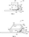
- Figure 3 illustrates a diagram of the system 100 for detecting an anomaly in an object 104, according to an example of the subject disclosure.
- the system 100 includes a support frame 160 including one or more upright beams 162, and a cross beam 164 secures to the one or more upright beams 162.
- the support frame 160 can be disposed on the object 104.
- the support frame 160 can be sized, shaped, and configured differently than shown.
- the support frame 160 can include more upright beams 162 and cross beams 164 than shown.
- the beams 162 and 164 can be oriented differently than shown.
- the imaging device 140 is secured to a portion of the cross beam 164.
- the light source 112 is mounted to a portion of the upright beam(s) 162.
- the couplant applicator 142 includes a fluid reservoir 166 that stores the optical couplant 116, and a pump 168 that is configured to output the optical couplant 116 onto the object 104 (and between the object 104 and the light transmission element 114) through a fluid delivery line 170, such as one or more tubes, conduits, or the like.
- the control unit 144 is configured to control the light source 112, the imaging device 140, and the couplant applicator 142.
- the system 100 can also include a moveable arm 174 secured to the light transmission element 114, and moveable coupled the upright beam(s) 162.
- the moveable arm 174 is configured to be operated to move the light transmission element 114 to a desired position.
- the moveable arm 174 is operatively coupled to a motor or other such actuator, which can be controlled by the control unit 144.
- Figure 4 illustrates a diagram of the system 100 for detecting an anomaly in an object 104, according to an example of the subject disclosure.
- the system 100 includes a base 180 having a plurality of wheels 182 that are configured to roll over the object 104.
- the support frame 160 is secured to the base 180.
- One or more of the wheels 182 can be powered, such as via a motor, and controlled by the control unit 144 (shown in Figure 2 ).
- the system 100 can be part of a crawler vehicle that is configured to travel over the object 104.
- the light transmission element 114 can be coupled to a compliant mirror support mechanism 184, which can include a spring-loaded parallelogram linkage, for example.
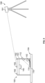
- Figure 5 illustrates a diagram of the system 100 for detecting an anomaly in an object 104, according to an example of the subject disclosure.
- an external localization system 190 can be used to register images of the object with a local coordinate system.
- the external localization system 190 includes an imaging device 191 (such as a camera, electromagnetic tracking system, and/or the like), and optionally a laser measurement device.
- the imaging device 191 is configured to image a plurality of fiducials 192 disposed on a support frame 193 that retains the imaging device 140, the light source 112, and the light transmission element 114, for example.
- the fiducials 192 are used to locate the various components, such as the support frame 193, in relation to images acquired by the imaging device 140.
- Information obtained by the external location system 190 can be combined with the image measurements from the pixel coordinates of the anomalies determined from the image difference detection, to produce location data for the anomalies in a specified coordinate system.
- an external location system 190 may not be used.
- Figure 6 illustrates a flow chart of a method of detecting an anomaly in an object, according to an example of the subject disclosure.
- the system 100 is placed on a target surface, such as the object 104 (a window, for example).
- the optical couplant 116 is applied on a bottom surface of the light transmission element 114.
- the light transmission element 114 is placed with the optical couplant 116 side onto the target surface. That is, the optical couplant 116 is disposed between and in contact with the light transmission element 114 and the object 104.
- ambient light can be shielded, such as via an opaque shroud, cover, or the like.
- the light source 112 is activated to illuminate the light transmission element 114.
- the imaging device 140 is operated to acquire one or more images of the object 104.
- the control unit 144 uses image processing techniques (such as difference detection methods) in relation to the image(s) to find potential anomalies, and identifies the locations of such anomalies in the image(s).
- the control unit 144 can then record such anomalies, such as within a memory.
- control unit 144 can determine if an external localization system is available. If not, the method proceeds to 218 to determine if there are more inspection areas to evaluate. If so, the method continues to 220, at which the system 100 is moved, and the method then returns to 200. If not, the method ends.
- the method proceeds to 222, at which the control unit 144 determines location data for areas of interest in a coordinate system of the object 104. Then, at 224, the control unit 144 records location data for maintenance records, and the method proceeds to 218.
- Figure 7 illustrates a side view of the system 100 for detecting an anomaly in an object 104, according to an example of the subject disclosure.
- Figure 8 illustrates an end view of the system 100 of Figure 7.
- Figure 9 illustrates a top view of the system 100 of Figure 7 .
- the object 104 can be a window secured within a frame 105, such as a portion of a fuselage of an aircraft.
- the system 100 includes a support frame 160 including upright beams 162 and a cross beam 164 secures to the upright beams 162.
- Contact components 300 such as elastomeric feet or rollers, extend toward the target surface.
- the contact components 300 abut the frame 105.
- a couplant distributor 302 can be secured around a periphery of the light transmission element 114.
- the couplant distributor 302 is in fluid communication with the couplant applicator 142, such as via fluid conduits 304 in communication with a pump 306.
- the light transmission element 114 is coupled to an articulating arm 308, which is, in turn, operatively coupled to a motor 310.
- the control unit 144 (shown in Figure 2 ) is configured to operate the motor 310 to move the light transmission element 114 via the articulating arm 308, as desired.
- a rotator 320 can be operatively coupled to the support frame 160.
- the rotator 320 includes a rotatable joint 322 operatively coupled to an actuator 324, which is configured to rotate the system 100 about an axis 326.
- the imaging device 140 acquires one or more images of the object 104 when the system 100 is in a first orientation, as shown in Figure 9 .
- the rotator 320 is configured to rotate the system 100 to a second orientation that differs from the first orientation. For example, the rotator 320 rotates the system 100 180 degrees about the axis 326 to ensure that the light transmission element 114 is moved from its previous position.
- the imaging device 140 then takes another image of the object 104 to ensure that the area that may have previously been covered by the light transmission element 114 is exposed.
- the first image(s) and the second image(s) can then be analyzed by the control unit 144 (shown in Figure 2 ) to determine locations of any anomaly.
- control unit 144 is configured to receive image data from the imaging device 140, and process the image data to detect an outer frame or periphery of the object 104. As such, the control unit 144 can utilize image processing to determine a location of the object 104.
- Figure 10 illustrates a side view of the couplant distributor 302 disposed around the light transmission element 114, according to an example of the subject disclosure.
- Figure 11 illustrates a top view of the couplant distributor 302 disposed around the light transmission element 114 of Figure 10.
- Figure 12 illustrates a bottom view of the couplant distributor 302 disposed around the light transmission element 114 of Figure 10 .
- the couplant distributor 302 is an outer ring 303 defining an internal fluid passage 309 that is in fluid communication with the fluid conduit 304.
- Fluid outlets 330 are formed in the bottom surface of the outer ring 303.
- the fluid outlets 330 are in fluid communication with the internal fluid passage 309.
- the optical couplant 116 is deposited out of the couplant distributor 302 via the fluid outlets 330.
- the couplant distributor 302 can be circular, oval-shaped, or the like.
- the couplant distributor 302 can be sized and shaped differently than shown.
- the couplant distributor 302 can be rectangular, square shaped, triangularly shaped, irregularly shaped, or the like.
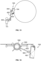
- Figure 13 illustrates a side view of a system 100 for detecting an anomaly in an object 104, according to an example of the subject disclosure.
- the system 100 includes a handle 400 secured to the support frame 160.
- the handle 400 is configured to be held by an individual 402.
- the handle 400 can include a telescoping portion 403, and a pivotal head 404, for example.
- the support frame 160 can be secured to a backpack, shoulder-mounted assembly, and/or the like.
- Figure 14 illustrates a side view of a system 100 for detecting an anomaly in an object, according to an example of the subject disclosure.
- a vehicle 500 such as an unmanned aerial vehicle (UAV) couples to the support frame 160 through an arm 502.
- the arm 502 can be coupled to a pivotal joint 504 that pivotally couples to the support frame 160.
- An opposite end of the arm 502 can be coupled to a rotatable ring 506 of the vehicle 500.
- UAV unmanned aerial vehicle
- Figure 15 illustrates a side view of a system 100 for detecting an anomaly in an object 104, according to an example of the subject disclosure.
- the support frame 160 is moveably coupled to one or more articulating arms 600 of a stationary robot 602 fixed to a floor or ground.
- Figure 16 illustrates a side view of a system 100 for detecting an anomaly in an object 104, according to an example of the subject disclosure.
- the support frame 160 is moveably coupled to one or more articulating arms 700 of a mobile base 702, which is configured to move over a floor or ground.
- the mobile base can also be attached to an overhead gantry or other track-lick structure.
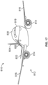
- Figure 17 illustrates a perspective front view of an aircraft 810, according to an example of the subject disclosure.
- the aircraft 810 includes a propulsion system 812 that includes engines 814, for example.
- the propulsion system 812 may include more engines 814 than shown.
- the engines 814 are carried by wings 816 of the aircraft 810.
- the engines 814 may be carried by a fuselage 818 and/or an empennage 820.
- the empennage 820 may also support horizontal stabilizers 822 and a vertical stabilizer 824.
- the fuselage 818 of the aircraft 810 defines an internal cabin 830, which includes a flight deck or cockpit, one or more work sections (for example, galleys, personnel carry-on baggage areas, and the like), one or more passenger sections (for example, first class, business class, and coach sections), one or more lavatories, and/or the like.
- the fuselage 818 includes one or more objects, such as windows, which are configured to be engaged by the systems 100 shown and described with respect to Figures 1-16 .
- examples of the subject disclosure may be used with various other vehicles, such as automobiles, buses, locomotives and train cars, watercraft, and the like. Further, examples of the subject disclosure may be used with respect to fixed structures, such as commercial and residential buildings.
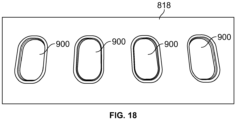
- Figure 18 illustrates a side view of windows 900 within the fuselage 818, according to an example of the subject disclosure.
- the windows 900 are examples of objects 104, such as shown and described with respect to Figures 1-16 .
- Figure 19 illustrates a flow chart of a method of identifying an anomaly of an object, according to an example of the subject disclosure.
- the method includes disposing (1000) the optical couplant 116 between the light transmission element 114 and the object 104; emitting (1002) from the light source 112, light 120 onto the textured surface 126 of the light transmission element 114; passing (1004) at least a portion of the light 120 (such as the rays 121) emitted by the light source 112 into the light transmission element 114 through the textured surface 126; passing (1006) the at least a portion of the light 120 into the object 104 through the optical couplant 116; internally reflecting (1008) at least a portion of the light 120 (such as the ray 121') that passes into the object 104 within the object 104; impinging (1010) the at least a portion of the light 120 that is internally reflected within the object 104 on the anomaly 102; and illuminating (1012) (such as via illumination 130) the location
- examples of the subject disclosure provide systems and methods for detecting anomalies in objects, such as transparent or translucent structures (for example, windows, windshields, or the like). Further, examples of the subject disclosure provide systems and methods that allow individuals to readily identify anomalies in such objects.
- a structure, limitation, or element that is "configured to” perform a task or operation is particularly structurally formed, constructed, or adapted in a manner corresponding to the task or operation.
- an object that is merely capable of being modified to perform the task or operation is not “configured to” perform the task or operation as used herein.
Landscapes
- Physics & Mathematics (AREA)
- General Physics & Mathematics (AREA)
- General Health & Medical Sciences (AREA)
- Chemical & Material Sciences (AREA)
- Analytical Chemistry (AREA)
- Biochemistry (AREA)
- Life Sciences & Earth Sciences (AREA)
- Health & Medical Sciences (AREA)
- Immunology (AREA)
- Pathology (AREA)
- Engineering & Computer Science (AREA)
- Aviation & Aerospace Engineering (AREA)
- Optics & Photonics (AREA)
- Length Measuring Devices By Optical Means (AREA)
- Geophysics And Detection Of Objects (AREA)
Abstract
Description
- Examples of the subject disclosure generally relate to systems and methods for detecting anomalies, such as cracks, scratches, nicks, chips, grooves, cuts, or the like, in objects, such as windows.
- Windows, windshields, and other transparent or translucent objects may be susceptible to anomalies. For example, a foreign object may impact such objects, thereby causing an anomaly such as a crack, scratch, nick, chip, pit, gouge, groove, divot, or the like to form. However, such an anomaly may not be readily visible to an individual.
- Various vehicles include windows. For example, commercial aircraft include fuselages including numerous windows. Typically, individuals such as mechanics or inspectors utilize a lift to visually examine the windows for scratches. As can be appreciated, such a process is time and labor intensive. Moreover, scratches and cracks within the windows can compromise the integrity of the windows, and can be difficult to see with the naked eye.
- A need exists for a system and a method for detecting an anomaly in an object, such as a transparent or translucent structure (for example, a window, windshield, or the like, which can be part of a vehicle). Further, a need exists for a system and a method that allow an individual to readily identify an anomaly in such an object.
- With those needs in mind, certain examples of the subject disclosure provide a system for detecting an anomaly of an object (for example, a transparent object, such as a window). The system includes a light source configured to emit light, a light transmission element having a textured surface, and an optical couplant configured to be disposed between the light transmission element and the object. At least a portion of the light emitted by the light source is configured to pass into the light transmission element through the textured surface and pass into the object through the optical couplant. At least a portion of the light that passes into the object internally reflects within the object and impinges on the anomaly to provide an illumination that indicates the location of the anomaly.
- As an example, the object is a window of a vehicle.
- In at least one example, the textured surface is formed on a first surface of the light transmission element. The first surface is opposite from a second surface that is smooth. The first surface is between the light source and the second surface. The textured surface includes a plurality of variances. The second surface is devoid of variances.
- In at least one example, the optical couplant comprises water.
- In at least one example, the light source is configured to emit the light onto the light transmission element at an acute angle.
- In at least one example, an imaging device is configured to acquire one or more images of the object as the light source emits the light onto the light transmission element.
- In at least one example, a couplant applicator is configured to apply the optical couplant between the light transmission element and the object.
- In at least one example, a control unit is in communication with the light source (and optionally other components). The control unit is configured to control operation of the light source (and optionally the other components).
- In at least one example, the system further includes a support frame. The light source and the light transmission element are coupled to the support frame. As a further example, the system also includes a base having a plurality of wheels. The base is coupled to the support frame.
- In at least one example, a rotator is coupled to the support frame. The rotator is configured to rotate the system between different orientations.
- In at least one example, a handle coupled to the support frame.
- In at least one example, an unmanned aerial vehicle (UAV) is coupled to the support frame.
- In at least one example, one or more articulating arms are coupled to the support frame. In at least one further example, a mobile base is coupled to the one or more articulating arms.
- In at least one example, a couplant distributor is configured to apply the optical couplant between the light transmission element and the object. In a further example, the couplant distributor includes an outer ring having a plurality of fluid outlets in fluid communication with an internal fluid passage.
- Certain examples of the subject disclosure provide a method for detecting an anomaly of an object. The method includes disposing an optical couplant between a light transmission element and the object; emitting, from a light source, light onto a textured surface of the light transmission element; passing at least a portion of the light emitted by the light source into the light transmission element through the textured surface; passing the at least a portion of the light into the object through the optical couplant; internally reflecting at least a portion of the light that passes into the object within the object; impinging the at least a portion of the light that is internally reflected within the object on the anomaly; and illuminating the location of the anomaly in response to said impinging.
-
-
Figure 1 illustrates a diagram of a system for detecting an anomaly in an object, according to an example of the subject disclosure. -
Figure 2 illustrates a diagram of the system for detecting an anomaly in an object, according to an example of the subject disclosure. -
Figure 3 illustrates a diagram of the system for detecting an anomaly in an object, according to an example of the subject disclosure. -
Figure 4 illustrates a diagram of the system for detecting an anomaly in an object, according to an example of the subject disclosure. -
Figure 5 illustrates a diagram of the system for detecting an anomaly in an object, according to an example of the subject disclosure. -
Figure 6 illustrates a flow chart of a method of detecting an anomaly in an object, according to an example of the subject disclosure. -
Figure 7 illustrates a side view of a system for detecting an anomaly in an object, according to an example of the subject disclosure. -
Figure 8 illustrates an end view of the system ofFigure 7 . -
Figure 9 illustrates a top view of the system ofFigure 7 . -
Figure 10 illustrates a side view of a couplant distributor disposed around a light transmission element, according to an example of the subject disclosure. -
Figure 11 illustrates a top view of the couplant distributor disposed around the light transmission element ofFigure 10 . -
Figure 12 illustrates a bottom view of the couplant distributor disposed around the light transmission element ofFigure 10 . -
Figure 13 illustrates a side view of a system for detecting an anomaly in an object, according to an example of the subject disclosure. -
Figure 14 illustrates a side view of a system for detecting an anomaly in an object, according to an example of the subject disclosure. -
Figure 15 illustrates a side view of a system for detecting an anomaly in an object, according to an example of the subject disclosure. -
Figure 16 illustrates a side view of a system for detecting an anomaly in an object, according to an example of the subject disclosure. -
Figure 17 illustrates a perspective front view of an aircraft, according to an example of the subject disclosure. -
Figure 18 illustrates a side view of windows within a fuselage, according to an example of the subject disclosure. -
Figure 19 illustrates a flow chart of a method of identifying an anomaly of an object, according to an example of the subject disclosure. - The foregoing summary, as well as the following detailed description of certain examples will be better understood when read in conjunction with the appended drawings. As used herein, an element or step recited in the singular and preceded by the word "a" or "an" should be understood as not necessarily excluding the plural of the elements or steps. Further, references to "one example" are not intended to be interpreted as excluding the existence of additional examples that also incorporate the recited features. Moreover, unless explicitly stated to the contrary, examples "comprising" or "having" an element or a plurality of elements having a particular condition can include additional elements not having that condition.
- Examples of the subject disclosure provide a system and a method for detecting anomalies in objects, such as transparent or translucent objects. The system and method utilize total internal reflection lighting in transparent or translucent panels (for example, windows) to highlight anomalies. A light source and an intermediary light transmission element are used to infuse light into an object at a range of angles that set up a total internal reflection condition in the target object with light entering the object from an exposed surface of the object (in contrast to an edge). When total internal reflection occurs in the target object, anomalies within the object are highlighted by the internal light and can be easily seen by an individual and/or automatically detected using image processing, for example. Examples of the subject disclosure allow to anomalies within objects to be quickly and easily detected.
-
Figure 1 illustrates a diagram of asystem 100 for detecting ananomaly 102 in anobject 104, according to an example of the subject disclosure. Theobject 104 can be a transparent or translucent panel, such as a window, windshield, table top, and/or the like. Theobject 104 can be formed of glass, plastic, and/or the like. In at least one example, theobject 104 is a window of a vehicle, such as a window in a fuselage of an aircraft. Theobject 104 includesperipheral edges 106, such as may be secured within a frame. As such, light from an exterior light source may not be able to enter theobject 104 through theperipheral edges 106, as the frame blocks the light from entering. Theobject 104 includes a first exposedsurface 108 and a second exposedsurface 110 connected to the first exposedsurface 108 by theperipheral edges 106 and/or interior structure. The first exposedsurface 108 is opposite from the second exposedsurface 110. The first exposedsurface 108 can be an exterior exposed surface, and the second exposedsurface 110 can be an interior exposed surface, or vice versa. - It is to be understood that the
object 104 is not shown to scale inFigure 1 . Instead, the thickness of theobject 104 is shown larger for illustrative purposes. - The
system 100 includes alight source 112, alight transmission element 114, and anoptical couplant 116. Thelight source 112 includes one or more light emitting elements 118 configured to emit light 120. For example, thelight source 112 can be a lamp having one or more light bulbs, light emitting diodes (LEDs), and/or the like that are configured to emit the light 120. - The
light transmission element 114 is formed of an optically transmissive material. For example, thelight transmission element 114 is formed of transparent glass, plastic, or the like. As a further example, thelight transmission element 114 is formed of clear acrylic. In at least one example, thelight transmission element 114 has the same or similar index of refraction as theobject 104. In at least one example, thelight transmission element 114 is formed of the same or similar material as theobject 104. - The
light transmission element 114 includes afirst surface 122 opposite from asecond surface 124. Thefirst surface 122 is proximate to thelight source 112, and thesecond surface 124 is proximate to theobject 104. As shown, thefirst surface 122 is between thelight source 112 and thesecond surface 124. Conversely, thesecond surface 124 is between theobject 104 and thefirst surface 122. - The
first surface 122 is textured. As such, thefirst surface 122 is atextured surface 126. In at least one example, thefirst surface 122 is not entirely textured. For example, thetextured surface 126 can be formed on less than entirety of thefirst surface 126. Thetextured surface 126 can be formed on an entirety or less than entirety of thefirst surface 122. Thetextured surface 126 can be a non-smooth surface that is roughened, scuffed, frosted, etched, machined, and/or other such surface. Thetextured surface 126 includes a plurality of variances 128 (such as grooves, channels, divots, and/or the like, which can be formed by application of a wire brush, file, sand paper, steel wool, and/or other surface preparation component, such as laser or chemical etching devices). Thevariances 128 provide areas where the light 120 can enter thelight transmission element 114. - In at least one example, the
variances 128 can be or otherwise include irregular features. In some examples, thevariances 128 can be or otherwise include regular pattern of features. - The
second surface 124 is not textured. Instead, thesecond surface 124 is smooth. Thesecond surface 124 can be devoid of variances. - The
optical couplant 116 is a light transmissive fluid. For example, theoptical couplant 116 is water. In some examples, theoptical couplant 116 is a clear gel. Theoptical couplant 116 can be applied to the first exposedsurface 108 of theobject 104 via a couplant applicator, which can be or otherwise include a bottle, reservoir, pump, and/or the like. In at least one example, an individual can apply theoptical couplant 116 to the first exposedsurface 108, whether or not from a dedicated couplant applicant applicator. - As shown, the
optical couplant 116 is disposed between the first exposedsurface 108 of theobject 104, and thesecond surface 124 of thelight transmission element 114. Theoptical couplant 116 directly contacts both the first exposedsurface 108 of theobject 104, and thesecond surface 124 of thelight transmission element 114. As such, theoptical couplant 116 is sandwiched between thelight transmission element 114 and theobject 104. Theoptical couplant 116 provides an uninterrupted pathway (for example, no air gaps) for light to travel between theobject 104 and thelight transmission element 114. Theoptical couplant 116 provides a smooth and even interface between thelight transmission element 114 and theobject 104, thereby compensating for surface curvature deviations or variances that may exist between thelight transmission element 114 and theobject 104. Accordingly, theoptical couplant 116 provides a consistent and even optical path between thelight transmission element 114 and theobject 104. - The
light source 112 is configured to emit the light 120 at an acute angle θ with respect to a plane of thefirst surface 122 of the light transmission element 114 (and/or a plane of the first exposedsurface 108 of the object 104). That is, eachray 121 of the light 120 impinges upon thefirst surface 122 at an acute angle θ (in relation to a central aim axis of the light source 112). As an example, the acute angle θ can be between 15-60 degrees. As a further example, the acute angle θ can be between 40-50 degrees. In some examples, the acute angle θ can be between 20-45 degrees. It has been found, through experimentation, that an acute angle θ between 20-45 degrees allows a plurality ofrays 121 to pass into thelight transmission element 114, into theobject 104 via theoptical couplant 116, and some of which internally reflect within theobject 104. Alternatively, the arcuate angle can be less than 15 degrees, or greater than 60 degrees. - In operation, the
light source 112 emits the light 120 having the plurality ofrays 121 onto the light transmission element 114 (and optionally, the first exposedsurface 108 of the object). Thevariances 128 in thetextured surface 126 allows at least some of therays 121 to pass into the light transmission element 114 (instead of reflecting off the first exposed surface 108). Therays 121 that pass into thelight transmission element 114 pass through thesecond surface 124 and into theoptical couplant 116, which abuts against thesecond surface 124. Theoptical couplant 116 provides a path for therays 121 to pass into the first exposedsurface 108 of theobject 104 and into theobject 104. Because thelight source 112 emitsnumerous rays 121 at acute angles θ that enter thelight transmission element 114 through the textured surface 126 (for example, via the variances), at least some of therays 121 pass through thelight transmission element 114 and into theobject 104 through theoptical couplant 116 at or greater than the critical angle needed for internal reflection within theobject 104. Certain (for example, less than all) rays 121' internally reflect within theobject 104 until impinging upon theanomaly 102. Because the anomaly provides an irregular surface within the object, the ray(s) 121' pass out of theobject 104 through theanomaly 102, thereby providing anillumination 130 that is readily visible, such as by an individual, a camera, and/or the like. In this manner, thesystem 100 allows for quick, easy, and ready detection of theanomaly 102. - As described herein, the
system 100 includes thelight transmission element 114 having thetextured surface 126. Theoptical couplant 116 is disposed between thelight transmission element 114 and theobject 104. Thelight source 112 emits the light 120 (which includes light rays 121) onto thetextured surface 126, which allowsrays 121 to pass into thelight transmission element 114, and subsequently pass into theobject 104 through theoptical couplant 116. At least some of therays 121 enter theobject 104 at or greater than the critical angle needed for internal reflection. At least some of therays 121 that internally reflect within theobject 104 impinge on theanomaly 102, thereby providing theillumination 130 that readily identifies theanomaly 102. - In at least one example, the
system 100 for detecting theanomaly 102 of the object 104 (such as on and/or within the object 104) includes thelight source 112, which is configured to emit the light 120 (which includes light rays 121). Thelight transmission element 114 includes thetextured surface 126. Theoptical couplant 116 is configured to be disposed between thelight transmission element 114 and theobject 104. At least a portion of the light 120 emitted by thelight source 112 is configured to pass into thelight transmission element 114 through thetextured surface 126 and pass into theobject 104 through theoptical couplant 116. At least a portion of the light 120 that passes into theobject 104 internally reflects within theobject 104 and impinges on theanomaly 102 to provide theillumination 130, which indicates the location of theanomaly 102. -
Figure 2 illustrates a diagram of thesystem 100 for detecting an anomaly in theobject 104, according to an example of the subject disclosure. Referring toFigures 1 and2 , in at least one example, thesystem 100 also includes animaging device 140 that is configured to acquire images of theobject 104 as thelight source 112 emits the light 120 onto thelight transmission element 114. Theimaging device 140 can be a photographic or video camera, for example. Optionally, thesystem 100 may not include theimaging device 140. - In at least one example, the
system 100 also includes acouplant applicator 142 that is configured to apply theoptical couplant 116 onto theobject 104. For example, thecouplant applicator 142 is configured to apply theoptical couplant 116 between thelight transmission element 114 and theobject 104. In at least one example, thecouplant applicator 142 includes one or more of a fluid-retaining vessel, such as a bottle, reservoir, or the like, a pump, an actuator, and/or the like. Optionally, thesystem 100 may not include thecouplant applicator 142. - In at least one example, the
system 100 also includes acontrol unit 144, which is configured to control operation of thesystem 100. Thecontrol unit 144 is in communication with thelight source 112, such as through one or more wired or wireless connections, and is configured to control operation of thelight source 112. Thecontrol unit 144 can also be in communication with theimaging device 140, such as through one or more wired or wireless connections, and is configured to control operation of theimaging device 140 and receive image data therefrom. Thecontrol unit 144 can also be in communication with thecouplant applicator 142, and is configured to control operation of thecouplant applicator 142. Optionally, thesystem 100 may not include thecontrol unit 144. - As used herein, the term "control unit," "central processing unit," "CPU," "computer," or the like may include any processor-based or microprocessor-based system including systems using microcontrollers, reduced instruction set computers (RISC), application specific integrated circuits (ASICs), logic circuits, and any other circuit or processor including hardware, software, or a combination thereof capable of executing the functions described herein. Such are exemplary only, and are thus not intended to limit in any way the definition and/or meaning of such terms. For example, the
control unit 144 may be or include one or more processors that are configured to control operation, as described herein. - The
control unit 144 is configured to execute a set of instructions that are stored in one or more data storage units or elements (such as one or more memories), in order to process data. For example, thecontrol unit 144 may include or be coupled to one or more memories. The data storage units may also store data or other information as desired or needed. The data storage units may be in the form of an information source or a physical memory element within a processing machine. - The set of instructions may include various commands that instruct the
control unit 144 as a processing machine to perform specific operations such as the methods and processes of the various examples of the subject matter described herein. The set of instructions may be in the form of a software program. The software may be in various forms such as system software or application software. Further, the software may be in the form of a collection of separate programs, a program subset within a larger program, or a portion of a program. The software may also include modular programming in the form of object-oriented programming. The processing of input data by the processing machine may be in response to user commands, or in response to results of previous processing, or in response to a request made by another processing machine. - The diagrams of examples herein may illustrate one or more control or processing units, such as the
control unit 144. It is to be understood that the processing or control units may represent circuits, circuitry, or portions thereof that may be implemented as hardware with associated instructions (e.g., software stored on a tangible computer readable storage medium, such as a computer hard drive, ROM, RAM, or the like) that perform the operations described herein. In examples including a computer readable storage medium, the computer readable storage medium may be transitory or non-transitory. The hardware may include state machine circuitry hardwired to perform the functions described herein. Optionally, the hardware may include electronic circuits that include and/or are connected to one or more logic-based devices, such as microprocessors, processors, controllers, or the like. Optionally, thecontrol unit 144 may represent processing circuitry such as one or more of a field programmable gate array (FPGA), application specific integrated circuit (ASIC), microprocessor(s), and/or the like. The circuits in various examples may be configured to execute one or more algorithms to perform functions described herein. The one or more algorithms may include aspects of examples disclosed herein, whether or not expressly identified in a flowchart or a method. - As used herein, the terms "software" and "firmware" are interchangeable, and include any computer program stored in a data storage unit (for example, one or more memories) for execution by a computer, including RAM memory, ROM memory, EPROM memory, EEPROM memory, and non-volatile RAM (NVRAM) memory. The above data storage unit types are exemplary only, and are thus not limiting as to the types of memory usable for storage of a computer program.
-
Figure 3 illustrates a diagram of thesystem 100 for detecting an anomaly in anobject 104, according to an example of the subject disclosure. In this example, thesystem 100 includes asupport frame 160 including one or moreupright beams 162, and across beam 164 secures to the one or moreupright beams 162. Thesupport frame 160 can be disposed on theobject 104. - The
support frame 160 can be sized, shaped, and configured differently than shown. For example, thesupport frame 160 can include moreupright beams 162 and crossbeams 164 than shown. Thebeams - The
imaging device 140 is secured to a portion of thecross beam 164. Thelight source 112 is mounted to a portion of the upright beam(s) 162. Thecouplant applicator 142 includes afluid reservoir 166 that stores theoptical couplant 116, and apump 168 that is configured to output theoptical couplant 116 onto the object 104 (and between theobject 104 and the light transmission element 114) through afluid delivery line 170, such as one or more tubes, conduits, or the like. Referring toFigures 1-3 , in at least one example, thecontrol unit 144 is configured to control thelight source 112, theimaging device 140, and thecouplant applicator 142. - The
system 100 can also include amoveable arm 174 secured to thelight transmission element 114, and moveable coupled the upright beam(s) 162. Themoveable arm 174 is configured to be operated to move thelight transmission element 114 to a desired position. In at least one example, themoveable arm 174 is operatively coupled to a motor or other such actuator, which can be controlled by thecontrol unit 144. -
Figure 4 illustrates a diagram of thesystem 100 for detecting an anomaly in anobject 104, according to an example of the subject disclosure. In this example, thesystem 100 includes a base 180 having a plurality ofwheels 182 that are configured to roll over theobject 104. Thesupport frame 160 is secured to thebase 180. One or more of thewheels 182 can be powered, such as via a motor, and controlled by the control unit 144 (shown inFigure 2 ). As such, thesystem 100 can be part of a crawler vehicle that is configured to travel over theobject 104. In at least one example, thelight transmission element 114 can be coupled to a compliantmirror support mechanism 184, which can include a spring-loaded parallelogram linkage, for example. -
Figure 5 illustrates a diagram of thesystem 100 for detecting an anomaly in anobject 104, according to an example of the subject disclosure. As shown, anexternal localization system 190 can be used to register images of the object with a local coordinate system. Theexternal localization system 190 includes an imaging device 191 (such as a camera, electromagnetic tracking system, and/or the like), and optionally a laser measurement device. Theimaging device 191 is configured to image a plurality offiducials 192 disposed on asupport frame 193 that retains theimaging device 140, thelight source 112, and thelight transmission element 114, for example. Thefiducials 192, as imaged by theimaging device 191, are used to locate the various components, such as thesupport frame 193, in relation to images acquired by theimaging device 140. Information obtained by theexternal location system 190 can be combined with the image measurements from the pixel coordinates of the anomalies determined from the image difference detection, to produce location data for the anomalies in a specified coordinate system. Optionally, anexternal location system 190 may not be used. -
Figure 6 illustrates a flow chart of a method of detecting an anomaly in an object, according to an example of the subject disclosure. Referring toFigures 1-6 , at 200, thesystem 100 is placed on a target surface, such as the object 104 (a window, for example). At 202, theoptical couplant 116 is applied on a bottom surface of thelight transmission element 114. At 204, thelight transmission element 114 is placed with theoptical couplant 116 side onto the target surface. That is, theoptical couplant 116 is disposed between and in contact with thelight transmission element 114 and theobject 104. Optionally, at 206, ambient light can be shielded, such as via an opaque shroud, cover, or the like. At 208, thelight source 112 is activated to illuminate thelight transmission element 114. - At 210, the
imaging device 140 is operated to acquire one or more images of theobject 104. At 212, thecontrol unit 144 uses image processing techniques (such as difference detection methods) in relation to the image(s) to find potential anomalies, and identifies the locations of such anomalies in the image(s). At 214, thecontrol unit 144 can then record such anomalies, such as within a memory. - Optionally, at 216, the
control unit 144 can determine if an external localization system is available. If not, the method proceeds to 218 to determine if there are more inspection areas to evaluate. If so, the method continues to 220, at which thesystem 100 is moved, and the method then returns to 200. If not, the method ends. - If, however, at 216, an external localization system is available, the method proceeds to 222, at which the
control unit 144 determines location data for areas of interest in a coordinate system of theobject 104. Then, at 224, thecontrol unit 144 records location data for maintenance records, and the method proceeds to 218. -
Figure 7 illustrates a side view of thesystem 100 for detecting an anomaly in anobject 104, according to an example of the subject disclosure.Figure 8 illustrates an end view of thesystem 100 ofFigure 7. Figure 9 illustrates a top view of thesystem 100 ofFigure 7 . Referring toFigures 7-9 , theobject 104 can be a window secured within aframe 105, such as a portion of a fuselage of an aircraft. - The
system 100 includes asupport frame 160 includingupright beams 162 and across beam 164 secures to the upright beams 162. Contactcomponents 300, such as elastomeric feet or rollers, extend toward the target surface. Thecontact components 300 abut theframe 105. Acouplant distributor 302 can be secured around a periphery of thelight transmission element 114. Thecouplant distributor 302 is in fluid communication with thecouplant applicator 142, such as viafluid conduits 304 in communication with apump 306. - The
light transmission element 114 is coupled to an articulatingarm 308, which is, in turn, operatively coupled to amotor 310. The control unit 144 (shown inFigure 2 ) is configured to operate themotor 310 to move thelight transmission element 114 via the articulatingarm 308, as desired. - A
rotator 320 can be operatively coupled to thesupport frame 160. Therotator 320 includes a rotatable joint 322 operatively coupled to anactuator 324, which is configured to rotate thesystem 100 about anaxis 326. - In operation, the
imaging device 140 acquires one or more images of theobject 104 when thesystem 100 is in a first orientation, as shown inFigure 9 . Because thelight transmission element 114 may block portions of theobject 104 from being imaged, therotator 320 is configured to rotate thesystem 100 to a second orientation that differs from the first orientation. For example, therotator 320 rotates thesystem 100 180 degrees about theaxis 326 to ensure that thelight transmission element 114 is moved from its previous position. Theimaging device 140 then takes another image of theobject 104 to ensure that the area that may have previously been covered by thelight transmission element 114 is exposed. The first image(s) and the second image(s) can then be analyzed by the control unit 144 (shown inFigure 2 ) to determine locations of any anomaly. - In at least one example, the
control unit 144 is configured to receive image data from theimaging device 140, and process the image data to detect an outer frame or periphery of theobject 104. As such, thecontrol unit 144 can utilize image processing to determine a location of theobject 104. -
Figure 10 illustrates a side view of thecouplant distributor 302 disposed around thelight transmission element 114, according to an example of the subject disclosure.Figure 11 illustrates a top view of thecouplant distributor 302 disposed around thelight transmission element 114 ofFigure 10. Figure 12 illustrates a bottom view of thecouplant distributor 302 disposed around thelight transmission element 114 ofFigure 10 . Referring toFigures 7-12 , in at least one example, thecouplant distributor 302 is anouter ring 303 defining aninternal fluid passage 309 that is in fluid communication with thefluid conduit 304.Fluid outlets 330 are formed in the bottom surface of theouter ring 303. Thefluid outlets 330 are in fluid communication with theinternal fluid passage 309. Theoptical couplant 116 is deposited out of thecouplant distributor 302 via thefluid outlets 330. - The
couplant distributor 302 can be circular, oval-shaped, or the like. Optionally, thecouplant distributor 302 can be sized and shaped differently than shown. For example, thecouplant distributor 302 can be rectangular, square shaped, triangularly shaped, irregularly shaped, or the like. -
Figure 13 illustrates a side view of asystem 100 for detecting an anomaly in anobject 104, according to an example of the subject disclosure. In this example, thesystem 100 includes ahandle 400 secured to thesupport frame 160. Thehandle 400 is configured to be held by an individual 402. Thehandle 400 can include a telescoping portion 403, and apivotal head 404, for example. In at least one other example, instead of a handle, thesupport frame 160 can be secured to a backpack, shoulder-mounted assembly, and/or the like. -
Figure 14 illustrates a side view of asystem 100 for detecting an anomaly in an object, according to an example of the subject disclosure. In this example, avehicle 500, such as an unmanned aerial vehicle (UAV) couples to thesupport frame 160 through anarm 502. Thearm 502 can be coupled to a pivotal joint 504 that pivotally couples to thesupport frame 160. An opposite end of thearm 502 can be coupled to arotatable ring 506 of thevehicle 500. -
Figure 15 illustrates a side view of asystem 100 for detecting an anomaly in anobject 104, according to an example of the subject disclosure. In this example, thesupport frame 160 is moveably coupled to one or more articulatingarms 600 of astationary robot 602 fixed to a floor or ground. -
Figure 16 illustrates a side view of asystem 100 for detecting an anomaly in anobject 104, according to an example of the subject disclosure. In this example, thesupport frame 160 is moveably coupled to one or more articulatingarms 700 of amobile base 702, which is configured to move over a floor or ground. In other examples, the mobile base can also be attached to an overhead gantry or other track-lick structure. -
Figure 17 illustrates a perspective front view of anaircraft 810, according to an example of the subject disclosure. Theaircraft 810 includes apropulsion system 812 that includesengines 814, for example. Optionally, thepropulsion system 812 may includemore engines 814 than shown. Theengines 814 are carried bywings 816 of theaircraft 810. In other examples, theengines 814 may be carried by afuselage 818 and/or anempennage 820. Theempennage 820 may also supporthorizontal stabilizers 822 and avertical stabilizer 824. - The
fuselage 818 of theaircraft 810 defines aninternal cabin 830, which includes a flight deck or cockpit, one or more work sections (for example, galleys, personnel carry-on baggage areas, and the like), one or more passenger sections (for example, first class, business class, and coach sections), one or more lavatories, and/or the like. Thefuselage 818 includes one or more objects, such as windows, which are configured to be engaged by thesystems 100 shown and described with respect toFigures 1-16 . - Alternatively, instead of an aircraft, examples of the subject disclosure may be used with various other vehicles, such as automobiles, buses, locomotives and train cars, watercraft, and the like. Further, examples of the subject disclosure may be used with respect to fixed structures, such as commercial and residential buildings.
-
Figure 18 illustrates a side view ofwindows 900 within thefuselage 818, according to an example of the subject disclosure. Thewindows 900 are examples ofobjects 104, such as shown and described with respect toFigures 1-16 . -
Figure 19 illustrates a flow chart of a method of identifying an anomaly of an object, according to an example of the subject disclosure. Referring toFigures 1 and19 , the method includes disposing (1000) theoptical couplant 116 between thelight transmission element 114 and theobject 104; emitting (1002) from thelight source 112, light 120 onto thetextured surface 126 of thelight transmission element 114; passing (1004) at least a portion of the light 120 (such as the rays 121) emitted by thelight source 112 into thelight transmission element 114 through thetextured surface 126; passing (1006) the at least a portion of the light 120 into theobject 104 through theoptical couplant 116; internally reflecting (1008) at least a portion of the light 120 (such as the ray 121') that passes into theobject 104 within theobject 104; impinging (1010) the at least a portion of the light 120 that is internally reflected within theobject 104 on theanomaly 102; and illuminating (1012) (such as via illumination 130) the location of theanomaly 102 in response to said impinging 1010. - Further, the disclosure comprises the subject matter described in the following clauses:
- Clause 1. A system for detecting an anomaly of an optically transparent or translucent object, the system comprising: a light source configured to emit light; a light transmission element having a textured surface; and an optical couplant configured to be disposed between the light transmission element and the object, wherein at least a portion of the light emitted by the light source is configured to pass into the light transmission element through the textured surface and pass into the object through the optical couplant, and wherein at least a portion of the light that passes into the object internally reflects within the object and impinges on the anomaly to provide an illumination that indicates the location of the anomaly.
-
Clause 2. The system of Clause 1, wherein the object is a window of a vehicle. - Clause 3. The system of
Clauses 1 or 2, wherein the textured surface is formed on a first surface of the light transmission element, wherein the first surface is opposite from a second surface that is smooth, and wherein the first surface is between the light source and the second surface. - Clause 4. The system of Clause 3, wherein the textured surface comprises a plurality of variances, and wherein the second surface is devoid of variances.
- Clause 5. The system of any of Clauses 1-4, wherein the optical couplant comprises one or more of water, optically clear liquid, or gel.
- Clause 6. The system of any of Clauses 1-5, wherein the light source is configured to emit the light onto the light transmission element at an acute angle.
- Clause 7. The system of any of Clauses 1-6, further comprising an imaging device configured to acquire one or more images of the object as the light source emits the light onto the light transmission element.
- Clause 8. The system of any of Clauses 1-7, further comprising a couplant applicator that is configured to apply the optical couplant between the light transmission element and the object.
- Clause 9. The system of any of Clauses 1-8, further comprising a control unit in communication with the light source, wherein the control unit is configured to control operation of the light source.
- Clause 9a. The system of Clause 9, wherein the control unit is configured to control operation of one or more of a camera, a couplant pump, or other components, as described herein.
- Clause 10. The system of any of Clauses 1-9a, further comprising a support frame, wherein the light source and the light transmission element are coupled to the support frame.
- Clause 11. The system of claim 10, further comprising a base having a plurality of wheels, wherein the base is coupled to the support frame.
- Clause 12. The system of Clauses 10 or 11, further comprising a rotator coupled to the support frame, wherein the rotator is configured to rotate the system between different orientations.
- Clause 13. The system of Clause 10, further comprising a handle coupled to the support frame.
- Clause 14. The system of Clause 10 further comprising an unmanned aerial vehicle (UAV) coupled to the support frame.
- Clause 15. The system of any of Clauses 10-14, further comprising one or more articulating arms coupled to the support frame.
- Claus 16. The system of Clause 15, further comprising a mobile base coupled to the one or more articulating arms.
- Clause 17. The system of any of Clauses 1-16, further comprising a couplant distributor configured to apply the optical couplant between the light transmission element and the object.
- Clause 18. The system of Clause 17, wherein the couplant distributor comprises an outer ring having a plurality of fluid outlets in fluid communication with an internal fluid passage.
- Clause 18a. The system of any preceding Clause, arranged to carry out the steps of the method of Clause 19.
- Clause 19. A method for detecting an anomaly of an object, the method comprising: disposing an optical couplant between a light transmission element and the object; emitting, from a light source, light onto a textured surface of the light transmission element; passing at least a portion of the light emitted by the light source into the light transmission element through the textured surface; passing the at least a portion of the light into the object through the optical couplant; internally reflecting at least a portion of the light that passes into the object within the object; impinging the at least a portion of the light that is internally reflected within the object on the anomaly; and illuminating the location of the anomaly in response to said impinging.
- Clause 19a. The method of Clause 19, performed using the system of any of Clauses 1 to 18a.
- Clause 20. A system for detecting an anomaly of an object, the system comprising: a light source configured to emit light; a light transmission element having a textured surface, wherein the textured surface is formed on a first surface of the light transmission element, wherein the first surface is opposite from a second surface that is smooth, wherein the first surface is between the light source and the second surface, wherein the textured surface comprises a plurality of variances, wherein the second surface is devoid of variances, and wherein the light source is configured to emit the light onto the light transmission element at an acute angle; a couplant applicator that is configured to apply optical couplant between the light transmission element and the object, wherein at least a portion of the light emitted by the light source is configured to pass into the light transmission element through the textured surface and pass into the object through the optical couplant, and wherein at least a portion of the light that passes into the object internally reflects within the object and impinges on the anomaly to provide an illumination that indicates the location of the anomaly; and an imaging device configured to acquire one or more images of the object as the light source emits the light onto the light transmission element.
- Clause 21. A method of using the system of Clause 20 to detect an anomaly of an object.
- Clause 22. A computer-readable storage medium comprising instructions which, when executed by a computer, cause the computer to carry out the steps of the method of Clauses 19, 19a or 21.
- As described herein, examples of the subject disclosure provide systems and methods for detecting anomalies in objects, such as transparent or translucent structures (for example, windows, windshields, or the like). Further, examples of the subject disclosure provide systems and methods that allow individuals to readily identify anomalies in such objects.
- While various spatial and directional terms, such as top, bottom, lower, mid, side, horizontal, vertical, front and the like can be used to describe examples of the subject disclosure, it is understood that such terms are merely used with respect to the orientations shown in the drawings. The orientations can be inverted, rotated, or otherwise changed, such that an upper portion is a lower portion, and vice versa, horizontal becomes vertical, and the like.
- As used herein, a structure, limitation, or element that is "configured to" perform a task or operation is particularly structurally formed, constructed, or adapted in a manner corresponding to the task or operation. For purposes of clarity and the avoidance of doubt, an object that is merely capable of being modified to perform the task or operation is not "configured to" perform the task or operation as used herein.
- It is to be understood that the above description is intended to be illustrative, and not restrictive. For example, the above-described examples (and/or aspects thereof) can be used in combination with each other. In addition, many modifications can be made to adapt a particular situation or material to the teachings of the various examples of the disclosure without departing from their scope. While the dimensions and types of materials described herein are intended to define the parameters of the various examples of the disclosure, the examples are by no means limiting and are exemplary examples. Many other examples will be apparent to those of skill in the art upon reviewing the above description. The scope of the various examples of the disclosure should, therefore, be determined with reference to the appended claims, along with the full scope of equivalents to which such claims are entitled. In the appended claims and the detailed description herein, the terms "including" and "in which" are used as the plain-English equivalents of the respective terms "comprising" and "wherein." Moreover, the terms "first," "second," and "third," etc. are used merely as labels, and are not intended to impose numerical requirements on their objects.
- This written description uses examples to disclose the various examples of the disclosure, including the best mode, and also to enable any person skilled in the art to practice the various examples of the disclosure, including making and using any devices or systems and performing any incorporated methods. The patentable scope of the various examples of the disclosure is defined by the claims, and can include other examples that occur to those skilled in the art. Such other examples are intended to be within the scope of the claims if the examples have structural elements that do not differ from the literal language of the claims, or if the examples include equivalent structural elements with insubstantial differences from the literal language of the claims.
Claims (15)
- A system (100) for detecting an anomaly (102) of an object (104), the system (100) comprising:a light source (112) configured to emit light (120);a light transmission element (114) having a textured surface (126); andan optical couplant (116) configured to be disposed between the light transmission element (114) and the object (104), wherein at least a portion of the light (120) emitted by the light source (112) is configured to pass into the light transmission element (114) through the textured surface (126) and pass into the object (104) through the optical couplant (116), and wherein at least the portion of the light (120) that passes into the object (104) internally reflects within the object (104) and impinges on the anomaly (102) to provide an illumination (130) that indicates a location of the anomaly (102).
- The system (100) of claim 1, wherein the object (104) is a window of a vehicle.
- The system (100) of claim 1 or 2, wherein the textured surface (126) is formed on a first surface (122) of the light transmission element (114), wherein the first surface (122) is opposite from a second surface (124) that is smooth, and wherein the first surface (122) is between the light source (112) and the second surface (124); and optionally wherein the textured surface (126) comprises a plurality of variances (128), and wherein the second surface (124) is devoid of variances (128).
- The system (100) of any preceding claim, wherein the optical couplant (116) comprises water, optically clear liquid, or gel.
- The system (100) of any preceding claim, wherein the light source (112) is configured to emit the light (120) onto the light transmission element (114) at an acute angle.
- The system (100) of any preceding claim, further comprising:an imaging device (191) configured to acquire one or more images of the object (104) as the light source (112) emits the light (120) onto the light transmission element (114); and/ora couplant applicator (142) that is configured to apply the optical couplant (116) between the light transmission element (114) and the object (104); and/ora control unit (144) in communication with the light source (112), wherein the control unit (144) is configured to control operation of the light source (112).
- The system (100) of any preceding claim, further comprising a support frame (160), wherein the light source (112) and the light transmission element (114) are coupled to the support frame (160).
- The system (100) of claim 7, further comprising a base (180) having a plurality of wheels (182), wherein the base (180) is coupled to the support frame (160).
- The system (100) of claim 7 or 8, further comprising a rotator coupled to the support frame (160), wherein the rotator is configured to rotate the system (100) between different orientations.
- The system (100) of claim 7, further comprising a handle coupled to the support frame (160).
- The system (100) of claim 7, further comprising an unmanned aerial vehicle 'UAV' coupled to the support frame (160).
- The system (100) of any of claims 7 to 11, further comprising one or more articulating arms coupled to the support frame (160); and optionally further comprising a mobile base (180) coupled to the one or more articulating arms.
- The system (100) of any preceding claim, further comprising a couplant distributor configured to apply the optical couplant (116) between the light transmission element (114) and the object (104).
- The system (100) of claim 13, wherein the couplant distributor comprises an outer ring having a plurality of fluid outlets in fluid communication with an internal fluid passage.
- A method for detecting an anomaly (102) of an object (104), the method comprising:disposing an optical couplant (116) between a light transmission element (114) and the object (104);emitting, from a light source (112), light (120) onto a textured surface (126) of the light transmission element (114);passing at least a portion of the light (120) emitted by the light source (112) into the light transmission element (114) through the textured surface (126);passing the at least a portion of the light (120) into the object (104) through the optical couplant (116); andinternally reflecting at least the portion of the light (120) that passes into the object (104) within the object (104);impinging the at least the portion of the light (120) that is internally reflected within the object (104) on the anomaly (102); andilluminating a location of the anomaly (102) in response to said impinging.
Applications Claiming Priority (1)
| Application Number | Priority Date | Filing Date | Title |
|---|---|---|---|
| US17/571,619 US12196689B2 (en) | 2022-01-10 | 2022-01-10 | Systems and methods for detecting anomalies in objects |
Publications (1)
| Publication Number | Publication Date |
|---|---|
| EP4209779A1 true EP4209779A1 (en) | 2023-07-12 |
Family
ID=83853075
Family Applications (1)
| Application Number | Title | Priority Date | Filing Date |
|---|---|---|---|
| EP22202310.3A Pending EP4209779A1 (en) | 2022-01-10 | 2022-10-18 | Systems and methods for detecting anomalies in objects |
Country Status (3)
| Country | Link |
|---|---|
| US (1) | US12196689B2 (en) |
| EP (1) | EP4209779A1 (en) |
| CN (1) | CN116448778A (en) |
Citations (7)
| Publication number | Priority date | Publication date | Assignee | Title |
|---|---|---|---|---|
| US20070165213A1 (en) * | 2003-12-30 | 2007-07-19 | Agency For Science, Technology And Research | Method and apparatus for detection of inclusion in glass |
| DE202011108834U1 (en) * | 2011-12-08 | 2012-01-23 | Fti Engineering Network Gmbh | Measuring device for detecting, evaluating and securing the results of damage to aircraft windows using the dark field illumination method |
| EP2538393A1 (en) * | 2011-06-24 | 2012-12-26 | Tomra Systems ASA | Reverse vending machine and method of detecting dirt in a reverse vending machine |
| US20180361595A1 (en) * | 2017-06-14 | 2018-12-20 | The Boeing Company | Method for Controlling Location of End Effector of Robot Using Location Alignment Feedback |
| US20190311555A1 (en) * | 2018-04-04 | 2019-10-10 | The Boeing Company | Mobile visual-inspection system |
| US20210129971A1 (en) * | 2019-11-01 | 2021-05-06 | The Boeing Company | System and method for measuring localized characteristics of a transparency |
| US20210266461A1 (en) * | 2018-07-04 | 2021-08-26 | c/o H3 DYNAMICS PTE. LTD. | Defect detection system using a camera equipped uav for building facades on complex asset geometry with optimal automatic obstacle deconflicted flightpath |
Family Cites Families (4)
| Publication number | Priority date | Publication date | Assignee | Title |
|---|---|---|---|---|
| US3593015A (en) * | 1969-10-27 | 1971-07-13 | Gen Motors Corp | Headlamp washer pump |
| US7859655B2 (en) | 2007-09-28 | 2010-12-28 | The Boeing Company | Method involving a pointing instrument and a target object |
| US8744133B1 (en) | 2010-10-04 | 2014-06-03 | The Boeing Company | Methods and systems for locating visible differences on an object |
| US11315810B2 (en) * | 2019-05-17 | 2022-04-26 | Taiwan Semiconductor Manufacturing Company Ltd. | Apparatus for wafer processing |
-
2022
- 2022-01-10 US US17/571,619 patent/US12196689B2/en active Active
- 2022-10-18 EP EP22202310.3A patent/EP4209779A1/en active Pending
- 2022-10-18 CN CN202211272324.1A patent/CN116448778A/en active Pending
Patent Citations (7)
| Publication number | Priority date | Publication date | Assignee | Title |
|---|---|---|---|---|
| US20070165213A1 (en) * | 2003-12-30 | 2007-07-19 | Agency For Science, Technology And Research | Method and apparatus for detection of inclusion in glass |
| EP2538393A1 (en) * | 2011-06-24 | 2012-12-26 | Tomra Systems ASA | Reverse vending machine and method of detecting dirt in a reverse vending machine |
| DE202011108834U1 (en) * | 2011-12-08 | 2012-01-23 | Fti Engineering Network Gmbh | Measuring device for detecting, evaluating and securing the results of damage to aircraft windows using the dark field illumination method |
| US20180361595A1 (en) * | 2017-06-14 | 2018-12-20 | The Boeing Company | Method for Controlling Location of End Effector of Robot Using Location Alignment Feedback |
| US20190311555A1 (en) * | 2018-04-04 | 2019-10-10 | The Boeing Company | Mobile visual-inspection system |
| US20210266461A1 (en) * | 2018-07-04 | 2021-08-26 | c/o H3 DYNAMICS PTE. LTD. | Defect detection system using a camera equipped uav for building facades on complex asset geometry with optimal automatic obstacle deconflicted flightpath |
| US20210129971A1 (en) * | 2019-11-01 | 2021-05-06 | The Boeing Company | System and method for measuring localized characteristics of a transparency |
Also Published As
| Publication number | Publication date |
|---|---|
| CN116448778A (en) | 2023-07-18 |
| US20230221263A1 (en) | 2023-07-13 |
| US12196689B2 (en) | 2025-01-14 |
Similar Documents
| Publication | Publication Date | Title |
|---|---|---|
| US11718419B2 (en) | Aircraft inspection systems and methods | |
| KR102277633B1 (en) | Automatic robot measuring system for transit tunnel safety inspection | |
| CN105873825B (en) | Collaborative robot for carrying out visual inspection to aircraft | |
| US8392045B2 (en) | System and methods for aircraft preflight inspection | |
| KR102675315B1 (en) | Systems and methods for automatically inspecting surfaces | |
| JP5873500B2 (en) | Automatic visual inspection system | |
| EP3426558B1 (en) | Method for analysing an aircraft, corresponding system of analysis of an aircraft, and de-icing and/or anti- icing system | |
| GB2552092A (en) | Inspection system and method for automatic visual inspection of a motor vehicle | |
| US9541505B2 (en) | Automated postflight troubleshooting sensor array | |
| US20090217468A1 (en) | Method for automated docking of a passenger bridge or a goods handling bridge to a door of an aircraft | |
| CN116257930A (en) | Three-dimensional detecting twins for remote visual detection of vehicles | |
| EP4209779A1 (en) | Systems and methods for detecting anomalies in objects | |
| CA2469416C (en) | Centreline identification in a docking guidance system | |
| US9996946B2 (en) | Maintenance supporting system and maintenance supporting method utilizing a reference image and indicator | |
| CN103454220A (en) | Scanning region positioning device in residual ice detection process of airplane | |
| CN109383091A (en) | The method of refractive index characteristics part is hidden on laminated glass panel assembly and detection laminated glass panel assembly | |
| CN114644127A (en) | System for acquiring leading aircraft image from following aircraft under brightness reduction condition | |
| Mosca et al. | VISTA—Vision-based inspection system for automated testing of aircraft interiors: A panoramic view | |
| US20250124796A1 (en) | Runway Incursion Detection | |
| US10647445B2 (en) | Remote optical control surface indication system | |
| CN116721146B (en) | Device and method for detecting body dents based on point cloud data | |
| JP2024540925A (en) | Method and system for detecting optical defects in glass windshields - Patents.com | |
| Chávez-Aragón et al. | Rapid 3D Modeling and Parts Recognition on Automotive Vehicles Using a Network of RGB‐D Sensors for Robot Guidance | |
| US20250321593A1 (en) | System and method for enhanced airport ground operations | |
| CN110864632B (en) | Vehicle window glass detection system for security inspection |
Legal Events
| Date | Code | Title | Description |
|---|---|---|---|
| PUAI | Public reference made under article 153(3) epc to a published international application that has entered the european phase |
Free format text: ORIGINAL CODE: 0009012 |
|
| STAA | Information on the status of an ep patent application or granted ep patent |
Free format text: STATUS: THE APPLICATION HAS BEEN PUBLISHED |
|
| AK | Designated contracting states |
Kind code of ref document: A1 Designated state(s): AL AT BE BG CH CY CZ DE DK EE ES FI FR GB GR HR HU IE IS IT LI LT LU LV MC ME MK MT NL NO PL PT RO RS SE SI SK SM TR |
|
| STAA | Information on the status of an ep patent application or granted ep patent |
Free format text: STATUS: REQUEST FOR EXAMINATION WAS MADE |
|
| 17P | Request for examination filed |
Effective date: 20240105 |
|
| RBV | Designated contracting states (corrected) |
Designated state(s): AL AT BE BG CH CY CZ DE DK EE ES FI FR GB GR HR HU IE IS IT LI LT LU LV MC ME MK MT NL NO PL PT RO RS SE SI SK SM TR |
|
| STAA | Information on the status of an ep patent application or granted ep patent |
Free format text: STATUS: EXAMINATION IS IN PROGRESS |
|
| 17Q | First examination report despatched |
Effective date: 20241219 |