EP4209738A1 - Refrigerator and storage device for refrigerator - Google Patents
Refrigerator and storage device for refrigerator Download PDFInfo
- Publication number
- EP4209738A1 EP4209738A1 EP22213423.1A EP22213423A EP4209738A1 EP 4209738 A1 EP4209738 A1 EP 4209738A1 EP 22213423 A EP22213423 A EP 22213423A EP 4209738 A1 EP4209738 A1 EP 4209738A1
- Authority
- EP
- European Patent Office
- Prior art keywords
- storage device
- box body
- rotary
- rotary frame
- storage
- Prior art date
- Legal status (The legal status is an assumption and is not a legal conclusion. Google has not performed a legal analysis and makes no representation as to the accuracy of the status listed.)
- Withdrawn
Links
- 238000004891 communication Methods 0.000 claims description 3
- 230000007423 decrease Effects 0.000 claims description 3
- 238000000034 method Methods 0.000 claims description 3
- 238000005192 partition Methods 0.000 claims description 3
- 238000010586 diagram Methods 0.000 description 31
- 230000013011 mating Effects 0.000 description 14
- 230000009286 beneficial effect Effects 0.000 description 2
- 230000000694 effects Effects 0.000 description 2
- 230000004048 modification Effects 0.000 description 2
- 238000012986 modification Methods 0.000 description 2
- 238000000638 solvent extraction Methods 0.000 description 2
- 230000003044 adaptive effect Effects 0.000 description 1
- 230000000903 blocking effect Effects 0.000 description 1
- 230000001419 dependent effect Effects 0.000 description 1
- 238000005516 engineering process Methods 0.000 description 1
- 238000003466 welding Methods 0.000 description 1
Images





Classifications
-
- F—MECHANICAL ENGINEERING; LIGHTING; HEATING; WEAPONS; BLASTING
- F25—REFRIGERATION OR COOLING; COMBINED HEATING AND REFRIGERATION SYSTEMS; HEAT PUMP SYSTEMS; MANUFACTURE OR STORAGE OF ICE; LIQUEFACTION SOLIDIFICATION OF GASES
- F25D—REFRIGERATORS; COLD ROOMS; ICE-BOXES; COOLING OR FREEZING APPARATUS NOT OTHERWISE PROVIDED FOR
- F25D23/00—General constructional features
- F25D23/02—Doors; Covers
- F25D23/04—Doors; Covers with special compartments, e.g. butter conditioners
-
- F—MECHANICAL ENGINEERING; LIGHTING; HEATING; WEAPONS; BLASTING
- F25—REFRIGERATION OR COOLING; COMBINED HEATING AND REFRIGERATION SYSTEMS; HEAT PUMP SYSTEMS; MANUFACTURE OR STORAGE OF ICE; LIQUEFACTION SOLIDIFICATION OF GASES
- F25D—REFRIGERATORS; COLD ROOMS; ICE-BOXES; COOLING OR FREEZING APPARATUS NOT OTHERWISE PROVIDED FOR
- F25D11/00—Self-contained movable devices, e.g. domestic refrigerators
-
- F—MECHANICAL ENGINEERING; LIGHTING; HEATING; WEAPONS; BLASTING
- F25—REFRIGERATION OR COOLING; COMBINED HEATING AND REFRIGERATION SYSTEMS; HEAT PUMP SYSTEMS; MANUFACTURE OR STORAGE OF ICE; LIQUEFACTION SOLIDIFICATION OF GASES
- F25D—REFRIGERATORS; COLD ROOMS; ICE-BOXES; COOLING OR FREEZING APPARATUS NOT OTHERWISE PROVIDED FOR
- F25D2325/00—Charging, supporting or discharging the articles to be cooled, not provided for in other groups of this subclass
- F25D2325/021—Shelves with several possible configurations
-
- F—MECHANICAL ENGINEERING; LIGHTING; HEATING; WEAPONS; BLASTING
- F25—REFRIGERATION OR COOLING; COMBINED HEATING AND REFRIGERATION SYSTEMS; HEAT PUMP SYSTEMS; MANUFACTURE OR STORAGE OF ICE; LIQUEFACTION SOLIDIFICATION OF GASES
- F25D—REFRIGERATORS; COLD ROOMS; ICE-BOXES; COOLING OR FREEZING APPARATUS NOT OTHERWISE PROVIDED FOR
- F25D25/00—Charging, supporting, and discharging the articles to be cooled
- F25D25/005—Charging, supporting, and discharging the articles to be cooled using containers
Definitions
- Embodiments of the present invention relate to the technical field of household appliances, and in particular, to a refrigerator and a storage device for a refrigerator.
- a storage device such as a bottle rack is generally placed on the door of the refrigerator for storage of bottles, cans, and some other items.
- the storage space of the storage device such as a bottle rack is usually fixed, and when a relatively large number of items are required to be placed on the bottle rack, the storage space is generally insufficient, and the use flexibility of the storage space is relatively low.
- the technical problem solved by the present invention is the relatively low use flexibility of the storage space of the current storage device for a refrigerator.
- an embodiment of the present invention provides a storage device for a refrigerator.
- the storage device includes a storage box body, and further includes a rotary frame.
- the storage box body includes a bottom plate, and the storage box body is hinged to the rotary frame.
- the rotary frame includes a rotary plate. When the rotary frame is at a first position relative to the storage box body, the rotary plate is used as a side wall of the storage device, and the storage device is in a normal state.
- the rotary frame rotates relative to the storage box body until the rotary frame is at a second position relative to the storage box body, the rotary plate and the bottom plate of the storage box body are jointly used as a bottom wall of the storage device, the storage device is in an expanded state, and a storage space of the storage device in the expanded state is larger than the storage space in the normal state.
- the storage device for a refrigerator provided in the embodiment of the present invention may include a storage box body and a rotary frame.
- the storage box body is hinged to the rotary frame.
- the rotary frame includes a rotary plate. When the rotary frame is at a first position relative to the storage box body, the rotary plate is used as a side wall of the storage device, and the storage device is in a normal state.
- the storage device When the rotary frame rotates relative to the storage box body until the rotary frame is at a second position relative to the storage box body, the rotary plate and the bottom plate of the storage box body are jointly used as a bottom wall of the storage device, the storage device is in an expanded state, and a storage space of the storage device in the expanded state is larger than the storage space in the normal state.
- a size of the storage space of the storage device may be adjusted, so as to expand the storage space according to the actual demand, thereby improving the use flexibility of the storage space.
- the rotary plate is hinged to the bottom plate, and the rotary frame is rotatable around a hinge joint of the rotary plate and the bottom plate relative to the storage box body.
- the rotary frame includes a stop.
- the stop When the storage device is in the normal state, the stop is constructed to partition the storage space of the storage device into two parts. When the storage device is in the expanded state, the stop is constructed to limit a side surface of the storage space of the storage device.
- the stop includes a stop rod.
- the stop includes a baffle.
- the baffle When the storage device is in the normal state, the baffle is parallel to the rotary plate, and when the storage device is in the expanded state, the baffle is perpendicular to the rotary plate. Therefore, the position of the baffle in the mounting channel can be flexibly adjusted according to the state change of the storage device, so that the baffle varies with the expansion change of the storage device. An item in the storage device can be effectively protected and prevented from falling while the space use flexibility of the storage device is taken into account.
- the rotary frame includes a pair of first side plates.
- the pair of first side plates are respectively connected to two ends of the rotary plate.
- the rotary frame further includes a mounting channel arranged on the pair of first side plates.
- the mounting channel includes a first channel and a second channel in communication with each other.
- the first channel and the second channel respectively extend vertically and horizontally when the storage device is in the normal state.
- a connecting portion adapted to be received in the mounting channel is formed on each of two ends of the baffle facing the first side plates.
- the storage device for a refrigerator further includes a guide assembly.
- the guide assembly includes a guide groove and a guide member.
- One of the guide groove and the guide member is arranged on the storage box body, and the other of the guide groove and the guide member is arranged on the rotary frame.
- the guide assembly may be configured to guide the relative movement between the rotary frame and the storage box body, and may be further configured to limit the maximum moving position of the rotary frame relative to the storage box body.
- the guide groove may further play the role of supporting the guide member, which can increase the support force of the rotary frame and improve the bearing capacity of the storage device after expansion.
- the rotary frame includes a pair of first side plates.
- the pair of first side plates are respectively connected to two ends of the rotary plate.
- the other of the guide groove and the guide member is arranged on each of the first side plates.
- the rotary frame includes a stop, and two ends of the stop are detachably connected to the pair of first side plates respectively.
- the stop is configured to be detachably connected to the pair of first side plates according to the use state of the storage device.
- the stop may be mounted or removed according to requirements when the storage device is in a normal state, which improves the utilization flexibility of the storage space.
- the stop is mounted, so as to better protect the item stored in the storage device and prevent the item from falling.
- the storage box body includes a pair of second side plates.
- the pair of second side plates are respectively connected to two ends of the bottom plate.
- One of the guide groove and the guide member is arranged on each of the second side plates.
- an overlapping area of the first side plate and the second side plate gradually decreases. In this way, a neat appearance may be ensured for the storage device while the storage device is expanded.
- the storage device further includes a limiting assembly.
- the limiting assembly is configured to prevent the rotation of the rotary frame relative to the storage box body. In this way, when the storage device is in a normal state, it may be ensured that the relative positions of the rotary frame and the storage box body are fixed, to avoid a situation that the rotary frame rotates relative to the storage box body due to the dumping of item in the storage device during the use of the storage device.
- the limiting assembly includes a limiting slot and a limiting bulge.
- One of the limiting slot and the limiting bulge is arranged on the second side plate, the other of the limiting slot and the limiting bulge is arranged on the first side plate, and the limiting slot matches the limiting bulge.
- the rotary plate has a rotary shaft
- the bottom plate is provided with a first receiving cavity
- the rotary shaft is rotatably arranged in the first receiving cavity, so as to realize the hinge between the rotary frame and the storage box body.
- An embodiment of the present invention further provides a refrigerator, including a door and a storage device in any of the above.
- the storage box body of the storage device is connected to the door.
- FIG. 1 is a schematic diagram of a storage device according to an embodiment of the present invention in a normal state.
- FIG. 2 is an exploded view of FIG. 1 .
- FIG. 3 is a schematic diagram of a storage device according to an embodiment of the present invention in an expanded state.
- FIG. 4 is an exploded view of FIG. 3 .
- a structure of the storage device is described below with reference to FIG. 1 to FIG. 4 .
- a storage device 100 may be used in a refrigerator.
- the storage device 100 may be connected to a door of the refrigerator. Further, the storage device 100 is connected to a side of the door of the refrigerator facing a storage compartment of the refrigerator.
- the storage device 100 may include a storage box body 10 and a rotary frame 20.
- the rotary frame 20 may include a rotary plate 21.
- the storage box body 10 may include a bottom plate 11.
- the storage box body 10 is hinged to the rotary frame 20. Since the storage box body 10 is hinged to the rotary frame 20, the rotary frame 20 may rotate relative to the storage box body 10. When the rotary frame 20 is at a first position relative to the storage box body 10, the rotary plate 21 is used as a side wall 30 of the storage device 100. In this case, the storage device 100 is in a normal state.
- the storage device 100 When the rotary frame 20 rotates relative to the storage box body 10 until the rotary frame 20 is at a second position relative to the storage box body 10, the rotary plate 21 and the bottom plate 11 of the storage box body 10 are jointly used as a bottom wall 40 of the storage device 100. In this case, the storage device 100 is in an expanded state.
- a storage space 90 of the storage device 100 in the expanded state is larger than the storage space 90 in the normal state. That is to say, when the storage device 100 is changed from the normal state to the expanded state, a size of the storage space 90 can be increased.
- the side wall 30 may be parallel to the door.
- the storage box body 10 when the storage device 100 is used in the refrigerator, in order to facilitate the expansion operation of the storage device 100, the storage box body 10 is closer to the door than the rotary frame 20, and is connected to the door through the storage box body 10.
- the storage device 100 is configured to be far away from the door relative to the rotary frame 20, to cause the rotary frame 20 to be exposed to the outside, thereby providing a larger operating space. In this way, the storage device 100 may be expanded without disassembly when needed, enabling a more convenient expansion operation.
- the rotary plate 21 is hinged to the bottom plate 11, and the rotary frame 20 is rotatable around a hinge joint of the rotary frame 20 and the bottom plate 11 relative to the storage box body 10.
- the rotary frame 20 may further include a stop 26.
- the stop 26 is constructed to partition the storage space 90 of the storage device 100 into two parts.
- the stop 26 When the storage device 100 is in the expanded state, the stop 26 is constructed to limit a side surface of the storage space 90 of the storage device 100, and is used as the side wall 30 of the storage device 100.
- the stop 26 On the one hand, when the storage device 100 is in the normal state, the stop 26 does not affect the utilization of the storage space 90 of the storage device 100, and on the other hand, when the storage device 100 is in the expanded state, the stop 26 is used as the side wall 30 of the storage device 100 to define the storage space 90.
- the stop 26 can protect the item placed in the storage device 100 to prevent the item in the storage device 100 from falling.
- the stop 26 may be configured in various suitable shapes.
- the stop 26 may be configured as a stop rod, a baffle, or the like.
- the stop rod may be in a suitable shape such as a straight-line shape, a curved wave shape, or the like.
- the storage space 90 of the storage device 100 may be unevenly partitioned into two parts, so that the two spaces resulting from the partitioning may present alternating smaller and larger internal sizes, thereby satisfying placing requirements of items of different sizes.
- the curved and wavy stop rod may have a plurality of different blocking heights when being used as the side wall 30 of the storage device 100, to satisfy storage requirements of items with different heights.
- the connection mode of the stop 26 is configured as detachable connection.
- the rotary frame 20 includes a pair of first side plates 22 opposite to each other, two ends of the stop 26 are detachably connected to the pair of first side plates 22 respectively.
- the stop 26 is configured to be detachably connected, so that the stop 26 is reasonably mounted or detached according to a use state of the storage device 100.
- the stop 26 may be mounted, and the stop 26 may be used as the side wall 30 of the storage space 90 to protect the item stored in the storage device 100 from falling.
- the stop 26 may be disassembled to ensure the integrity of the storage space 90, so as to fully and flexibly utilize the storage space, without being limited by the partitioning of the storage space 90 by the stop 26.
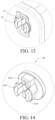
- FIG. 13 is a schematic diagram of mounting of an assembling member and a mounting port according to an embodiment of the present invention.
- FIG. 14 is a schematic structural diagram of an assembling member according to an embodiment of the present invention.
- FIG. 15 is a partial schematic structural diagram of a first side plate according to an embodiment of the present invention.
- the storage device 100 may further include an assembling member 262 and an assembly mating portion 263 which are detachable and mountable and configured to mate with the stop 26.
- a number of assembly mating portions 263 may be two, which are respectively arranged at two ends of the stop 26, and the assembly mating portion 263 matches the assembling member 262.
- the assembly mating portion 263 may be integrally formed on the stop 26 and is used as a part of the stop 26.
- the assembly mating portion 263 may further be relatively independent from the stop 26, and may be detachably connected to the stop 26 through suitable connection modes such as bonding, engagement, threaded connection, and the like, or fixedly connected to the stop 26 through suitable connection modes such as welding, riveting, and the like.
- the assembly mating portion 263 may be provided with a limiting rib 2631.
- the limiting rib 2631 protrudes from an outer surface of the assembly mating portion 263 and extends away from the outer surface of the assembly mating portion 263.
- the limiting rib 2631 may be used to limit relative positions of the assembly mating portion 263 and the assembling member 262 to prevent the assembly mating portion 263 from moving relative to the assembling member 262, to ensure the assembly firmness of the stop rod 26, and prevent the stop rod 26 from loosening, thereby preventing the item in the storage device 100 from falling due to the loosening of the stop rod 26.
- the first side plate 22 may be provided with a mounting port 261, the mounting port 261 matches the assembling member 262 to connect the assembling member 262 to the mounting port 261.
- the assembling member 262 may be provided with a pair of hooking portions 2621 and an accommodating portion 2622.
- the hooking portion 2621 may be a pair of hooks. The pair of hooks may be deformed after being squeezed by the mounting port 261, and is caught by the mounting port 261 after passing through the mounting port 261, to connect the stop 26 to the first side plate 22.
- the accommodating portion 2622 is configured to accommodate the assembly mating portion 263.
- the baffle when the stop 26 is a baffle, the baffle may be configured to rotate relative to the rotary plate 21. Specifically, when the storage device 100 is in a normal state, the baffle is parallel to the rotary plate 21, and when the storage device 100 is in the expanded state, the baffle is perpendicular to the rotary plate 21. In this way, when the storage device 100 is in a normal state, the baffle is parallel to the rotary plate 21, so that the occupation of the opening of the storage space 90 by the baffle can be minimized, which facilitates full utilization of the storage space 90. When the storage device 100 is in the expanded state, the baffle is perpendicular to the rotary plate 21.
- the rotary plate 21 is used as the bottom wall 40 of the storage device 100, that is to say, the baffle is perpendicular to the bottom wall 40.
- the baffle can have a better resisting effect, better protect the item in the storage device 100, and prevent the item from falling.
- the rotary frame 20 may include a pair of first side plates 22.
- the pair of first side plates 22 are respectively connected to two ends of the rotary plate 21.
- the rotary frame 20 may further include a mounting channel, and the pair of first side plates 22 are respectively provided with the mounting channel.
- the mounting channel includes a first channel and a second channel in communication with each other. When the storage device 100 is in the normal state, the first channel extends vertically and the second channel extends horizontally.
- a connecting portion adapted to be received in the mounting channel is formed on each of two ends of the baffle facing the first side plates 22, that is, the connecting portion is connected to the mounting channel. When the storage device 100 is in the normal state, the connecting portion is located in the first channel.
- the baffle is parallel to the rotary plate 21, to minimize the occupation of the opening of the storage device 100 by the baffle, which facilitates full utilization of the storage space 90.
- the connecting portion is located in the second channel.
- the rotary plate 21 is used as the bottom wall 40 of the storage device 100, that is to say, the baffle is perpendicular to the bottom wall 40.
- the baffle can have a better resisting effect, better protect the item in the storage device 100, and prevent the item from falling. Therefore, the position of the baffle in the mounting channel can be flexibly adjusted according to the state change of the storage device 100, so that the baffle varies with the expansion change of the storage device 100. The item in the storage device 100 can be effectively protected and prevented from falling while the space use flexibility of the storage device 100 is taken into account.
- the storage device 100 may include a guide assembly 60.
- the guide assembly 60 may include a guide groove 61 and a guide member 62.
- One of the guide groove 61 and the guide member 62 is arranged on the storage box body 10.
- the other of the guide groove 61 and the guide member 62 is arranged on the rotary frame 20.
- the guide member 62 moves along the guide groove 61.
- the guide assembly 60 may be configured to guide the relative movement between the rotary frame 20 and the storage box body 10, and may be further configured to limit the maximum moving position of the rotary frame 20 relative to the storage box body 10.
- the guide groove 61 may further play the role of supporting the guide member 62, which can increase the support force of the rotary frame 20 and improve the bearing capacity of the storage device 100 after expansion.
- the guide groove 61 may be arc-shaped.
- the guide member 62 may be cylindrical. In some embodiments, as long as a shape of the guide member 62 matches the guide groove 61, the guide groove 61 and the guide member 62 may be in other suitable shapes.
- the pair of first side plates 22 are respectively connected to two ends of the rotary plate 21.
- the other of the guide groove 61 and the guide member 62 is arranged on each of the first side plates 22.
- the storage box body 10 further includes a pair of second side plates 12.
- the pair of second side plates 12 are respectively connected to two ends of the bottom plate 11.
- the other of the guide groove 61 and the guide member 62 is arranged on each of the second side plates 12. That is to say, the guide groove 61 is arranged on the second side plate 12, and the guide member 62 is arranged on the first side plate 22.
- the guide groove 61 is arranged on the first side plate 22, and the guide member 62 is arranged on the second side plate 12.
- the guide groove 61 is arranged on the second side plate 12, and the guide member 62 is arranged on the first side plate 22.
- the pair of first side plates 22 may be located inside the pair of second side plates 12, so that a distance between the pair of first side plates 22 is less than a distance between the pair of second side plates 12.
- the guide groove 61 may extend through the second side plate 12, so as to observe the position of the guide member 62 in the guide groove 61, which also facilitates the assembly of the guide member 62 and the guide groove 61.
- the guide groove 61 may not extend through the second side plate 12. Specifically, the guide groove 61 does not extend through an outer surface of the second side plate 12, and a recess is formed by an inner surface of the second side plate 12 toward the outer surface. In this way, aesthetics of the overall appearance of the storage device 100 can be improved.
- the guide member 62 may be arranged on a side of the first side plate 22 facing the second side plate 12, that is to say, the guide member is arranged on an outer surface of the first side plate 22.
- the second side plate 12 may further include a first recessed portion 122 recessed toward the inside of the storage space 90.
- the inner surface of the first recessed portion 122 is basically on the same surface as the inner surface of the first side plate 22. In this way, the orderliness of the inner surface of the storage device 100 can be ensured when the storage device 100 is in a normal state.
- the first recessed portion 122 may be provided with a catching portion 1221.
- the catching portion 1221 is configured to mount the storage device 100 to the door. It should be noted that the catching portion 1221 is not limited to the roughly inverted U-shaped structure shown in the figure, but may be other suitable structures, as long as the storage device 100 can be mounted to the door, which is not limited herein.
- an overlapping area of the first side plate 22 and the second side plate 12 gradually decreases.
- an overlapping area of the first side plate 22 and the second side plate 12 is the largest.
- an overlapping area of the first side plate 22 and the second side plate 12 is the smallest.
- the storage device 100 may further include a limiting assembly 70.
- the limiting assembly 70 may be configured to prevent the rotation of the rotary frame 20 relative to the storage box body 10. In this way, when the storage device 100 is in the normal state, it may be ensured that the relative positions of the rotary frame 20 and the storage box body 10 are fixed, to avoid a situation that the rotary frame 20 rotates relative to the storage box body 10 due to the dumping of item in the storage device 100 during the use of the storage device 100.
- the limiting assembly 70 may include a limiting slot 71 and a limiting bulge 72.
- One of the limiting slot 71 and the limiting bulge 72 is arranged on the second side plate 12, and the other of the limiting slot 71 and the limiting bulge 72 is arranged on the first side plate 22.
- the limiting slot 71 matches the limiting bulge 72, and the relative positions of the storage box body 10 and the rotary frame 20 may be limited by the engagement of the limiting slot 71 and the limiting bulge 72.
- the accompanying drawings given by the embodiment of the present invention shows that the limiting slot 71 is arranged on the second side plate 12 and the limiting bulge 72 is arranged on the first side plate 22 by way of example.
- the limiting slot 71 is arranged on the first side plate 22 and the limiting bulge 72 is arranged on the second side plate 12
- the limiting slot and the limiting bulge may be adaptively deformed based on the given schematic diagrams, which are not illustrated herein.
- the limiting slot 71 may be a hole, and the limiting bulge 72 may be a columnar structure protruding from the second side plate 12.
- the limiting bulge 72 When the limiting bulge 72 is located in the limiting slot 71, the relative movement of the first side plate 22 and the second side plate 12 may be limited, and then the relative movement of the rotary frame 20 relative to the storage box body 10 is limited.
- the storage device 100 needs to be expanded, the limiting bulge 72 exits from the limiting slot 71, the engagement of the limiting bulge 72 with the limiting slot 71 is released, and the storage device 100 is changed from the normal state to the expanded state.
- the limiting slot 71 is not limited to the hole shown in the figure, and the limiting bulge 72 is not limited to the cylindrical structure, but may further be other structures with suitable shapes, as long as an internal shape of the limiting slot 71 matches an external shape of the limiting bulge 72.
- the specific structural form of the limiting assembly 70 is not limited to the limiting slot 71 and the limiting bulge 72 described above, and may further be other structural forms, such as an engagement structure, a hook structure, and the like, as long as the limiting assembly 70 can limit the relative positions of the storage box body 10 and the rotary frame 20 when the storage device 100 is in a normal state, to avoid the relative movement of the positions of the storage box body and the rotary frame.
- the limiting assembly 70 may further include a guiding portion 73.
- the guiding portion 73 is configured to guide the limiting bulge 72 into the limiting slot 71.
- the guiding portion 73 is arranged on the second side plate 12.
- the guiding portion 73 may extend from the limiting slot 71 to a first edge of the second side plate 12, the first edge of the second side plate 12 faces the rotary frame 20, and a surface of the guiding portion 73 is lower than a surface of the second side plate 12. That is to say, a partial region of the second side plate 12 is recessed to form the guiding portion 73.
- a width of the guiding portion 73 is gradually increased, and the guiding portion 73 is generally trumpet-shaped to better guide the limiting bulge 72 into the limiting slot 71.
- the rotary plate 21 has a rotary shaft 211
- the bottom plate 11 is provided with a first receiving cavity 111
- the rotary shaft 211 is rotatably arranged in the first receiving cavity 111, to realize the rotation of the rotary frame 20 relative to the storage box body 10.
- the first receiving cavity 111 is arranged at a first edge of the bottom plate 11 facing the rotary frame 20.
- the rotary shaft 211 is arranged at an edge of the rotary plate 21 facing the storage box body 10. Referring to FIG. 8, FIG.
- FIG. 8 is a partial schematic diagram of hinging of a rotary frame and a storage box body when a storage device according to an embodiment of the present invention is in a normal state.
- FIG. 9 is a partial schematic diagram of hinging of a rotary frame and a storage box body when a storage device according to an embodiment of the present invention is in an expanded state.
- the first receiving cavity 111 has an opening 1111.
- An extending direction of the first opening 1111 is the same as an axial direction of the rotary shaft 211.
- a width of the first opening 1111 may be less than a radius of the rotary shaft 211, to prevent the rotary shaft 211 from falling off from the first receiving cavity 111 while facilitating the mounting of the rotary shaft 211 in the first receiving cavity 111.
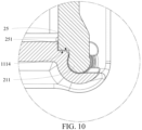
- FIG. 10 is a partial schematic diagram of engagement of a bump and a groove when a storage device according to an embodiment of the present invention is in a normal state.
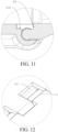
- FIG. 11 is a partial schematic diagram of relative positions of a bump and a groove when a storage device according to an embodiment of the present invention is in an expanded state.
- FIG. 12 is a partial schematic diagram of relative positions of a bump and a groove from another perspective when a storage device according to an embodiment of the present invention is in an expanded state.
- the rotary frame 20 may further include a plurality of bumps 25 arranged at intervals.
- the plurality of bumps 25 are connected to a partial surface of the rotary shaft 211.
- a plurality of grooves 1112 are arranged at intervals in the first receiving cavity 111.
- the grooves 1112 are used for receiving the bumps 25.
- each of the bumps 25 has a first stop surface 251, and the groove 1112 has a second stop surface 1114.
- the first stop surface 252 is engaged with the second stop surface 1114 to prevent the rotation of the rotary frame 20 relative to the storage box body 10.
- the storage box body 10 includes a pair of second side plates 12.
- the pair of second side plates 12 are respectively connected to two ends of the bottom plate 11.
- Each of the second side plates 12 is provided with a shaft hole 121, and the two ends of the rotary shaft 211 respectively extend through the corresponding shaft holes 121 to connect the rotary plate 21 to the storage box body 10.
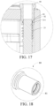
- FIG. 17 is a schematic diagram of relative positions of a rotary shaft and a torsion spring as well as a fixing portion according to an embodiment of the present invention.
- the storage device 100 may further include a fixing portion 80.
- the fixing portion 80 extends through the shaft hole 121 and is sleeved on an end of the rotary shaft 211 to rotatably connect the rotary shaft 211 to the second side plate 12.
- FIG. 18 is a schematic structural diagram of a fixing portion according to an embodiment of the present invention.
- the inside of the fixing portion 80 has a receiving groove 81
- the rotary shaft 211 has a protrusion 82.
- the receiving groove 81 matches the protrusion 82 and is used for receiving the protrusion 82.
- the receiving groove 81 is ring-shaped and is formed by recessing an inner surface of the fixing portion 80.
- the protrusion 82 may be formed by protruding an outer surface of the rotary shaft 211 toward the outside, and the protrusion 82 may be a continuous ring-shaped protrusion, or may be formed by a plurality of sub-protrusions axially arranged along the outer surface of the rotary shaft 211.
- the receiving groove 81 may further be arranged on the rotary shaft 211, and the protrusion 82 may further be arranged on the fixing portion 80.
- the receiving groove 81 may be ring-shaped and is formed by recessing an outer surface of the rotary shaft 211 toward the inside.
- the protrusion 82 may be formed by protruding the inner surface of the fixing portion 80 toward the inside, and the protrusion 82 may be a continuous ring-shaped protrusion, or may be formed by a plurality of sub-protrusions axially arranged along the outer surface of the rotary shaft 211.
- FIG. 5 is a schematic diagram of a state of a torsion spring when a storage device according to an embodiment of the present invention is in a normal state.
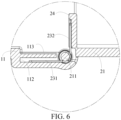
- FIG. 6 and FIG. 7 are respectively schematic diagrams of states of a torsion spring from different perspectives when a storage device according to an embodiment of the present invention is in an expanded state.
- the storage device 100 may further include a torsion spring 23.
- the torsion spring 23 is sleeved on two ends of the rotary shaft 211.
- a first end 231 of the torsion spring 23 is connected to the bottom plate 11, and a second end 232 of the torsion spring 23 is connected to the rotary frame 20.
- the torsion spring 23 may be configured such that when the storage device 100 is in a normal state, the torsion spring 23 is in a compressed state, and when the storage device 100 is in an expanded state, the torsion spring 23 is in a free state.
- the torsion spring 23 may adopt a 90° torsion spring.
- the storage device 100 includes the limiting assembly 70, and when the limiting bulge 72 is disengaged from the limiting slot 71, the torsion spring 23 is to be recovered from the compressed state to the free state.
- An elastic force of the torsion spring 23 can drive the rotary frame 20 to rotate relative to the storage box body 10, thereby realizing automatic switching of the storage device 100 from the normal state to the expanded state, and improving the simplicity of the expansion operation.
- the bottom plate 11 is provided with a second receiving cavity 112.
- the second receiving cavity 112 is used for receiving the first end 231 of the torsion spring 23. That is to say, the first end 231 of the torsion spring 23 is connected to the bottom plate 11 through the second receiving cavity 112.
- the rotary frame 20 is provided with an abutting plate 24.
- the abutting plate 24 is used for abutting against the second end 232 of the torsion spring 23.
- the abutting plate 24 is substantially parallel to the bottom plate 11.
- the abutting plate 24 is substantially perpendicular to the bottom plate 11.
- the bottom plate 11 may be further provided with a second recessed portion 113.
- the second recessed portion 113 is located above the second receiving cavity 112.
- the second recessed portion 113 is used for receiving the abutting plate 24.
- the storage device 100 may further include a side wall connected to the second side plate 12, and the side wall, a pair of second side plates 12, the bottom plate 11, and the rotary frame 20 jointly define a storage space 90 of the storage device 100.
- the storage device for a refrigerator may include the storage box body and the rotary frame.
- the storage box body is hinged to the rotary frame.
- the rotary frame includes a rotary plate. When the rotary frame is at a first position relative to the storage box body, the rotary plate is used as a side wall of the storage device, and the storage device is in a normal state.
- the storage device When the rotary frame rotates relative to the storage box body until the rotary frame is at a second position relative to the storage box body, the rotary plate and the bottom plate of the storage box body are jointly used as a bottom wall of the storage device, the storage device is in an expanded state, and a storage space of the storage device in the expanded state is larger than the storage space in the normal state.
- a size of the storage space of the storage device may be adjusted, so as to expand the storage space according to the actual demand, thereby improving the use flexibility of the storage space.
- An embodiment of the present invention further provides a refrigerator.
- the refrigerator includes a door and a storage device.
- the storage device is arranged on the door.
- the storage device may be the storage device 100 provided in any of the above embodiments, and the storage device 100 may be connected to the door through the storage box body 10 of the storage device 100.
- the storage device 100 may be connected to the door through the storage box body 10 of the storage device 100.
Landscapes
- Engineering & Computer Science (AREA)
- Chemical & Material Sciences (AREA)
- Combustion & Propulsion (AREA)
- Physics & Mathematics (AREA)
- Mechanical Engineering (AREA)
- Thermal Sciences (AREA)
- General Engineering & Computer Science (AREA)
- Refrigerator Housings (AREA)
Abstract
A storage device for a refrigerator, comprising a storage box body (10) and a rotary frame (20); the storage box body (10) comprises a bottom plate (11), and the storage box body (10) is hinged to the rotary frame (20); and the rotary frame (20) comprises a rotary plate (21), wherein when the rotary frame (20) is at a first position relative to the storage box body (10), the rotary plate (21) is used as a side wall (30) of the storage device (100), and the storage device (100) is in a normal state; and when the rotary frame (20) rotates relative to the storage box body (10) until the rotary frame (20) is at a second position relative to the storage box body (10), the rotary plate (21) and the bottom plate (11) of the storage box body (10) are jointly used as a bottom wall (40) of the storage device (100).
Description
- Embodiments of the present invention relate to the technical field of household appliances, and in particular, to a refrigerator and a storage device for a refrigerator.
- With the popularity of refrigerators in people's daily life, increasingly more people start using a refrigerator to store food. At present, a storage device such as a bottle rack is generally placed on the door of the refrigerator for storage of bottles, cans, and some other items. However, at present, the storage space of the storage device such as a bottle rack is usually fixed, and when a relatively large number of items are required to be placed on the bottle rack, the storage space is generally insufficient, and the use flexibility of the storage space is relatively low.
- The technical problem solved by the present invention is the relatively low use flexibility of the storage space of the current storage device for a refrigerator.
- In order to solve the above technical problem, an embodiment of the present invention provides a storage device for a refrigerator. The storage device includes a storage box body, and further includes a rotary frame. The storage box body includes a bottom plate, and the storage box body is hinged to the rotary frame. The rotary frame includes a rotary plate. When the rotary frame is at a first position relative to the storage box body, the rotary plate is used as a side wall of the storage device, and the storage device is in a normal state. When the rotary frame rotates relative to the storage box body until the rotary frame is at a second position relative to the storage box body, the rotary plate and the bottom plate of the storage box body are jointly used as a bottom wall of the storage device, the storage device is in an expanded state, and a storage space of the storage device in the expanded state is larger than the storage space in the normal state.
- Compared with the prior art, the technical solutions of the embodiments of the present invention have the following beneficial effects:
The storage device for a refrigerator provided in the embodiment of the present invention may include a storage box body and a rotary frame. The storage box body is hinged to the rotary frame. The rotary frame includes a rotary plate. When the rotary frame is at a first position relative to the storage box body, the rotary plate is used as a side wall of the storage device, and the storage device is in a normal state. When the rotary frame rotates relative to the storage box body until the rotary frame is at a second position relative to the storage box body, the rotary plate and the bottom plate of the storage box body are jointly used as a bottom wall of the storage device, the storage device is in an expanded state, and a storage space of the storage device in the expanded state is larger than the storage space in the normal state. By configuring the relative positions of the rotary frame and the storage box body, a size of the storage space of the storage device may be adjusted, so as to expand the storage space according to the actual demand, thereby improving the use flexibility of the storage space. - Optionally, the rotary plate is hinged to the bottom plate, and the rotary frame is rotatable around a hinge joint of the rotary plate and the bottom plate relative to the storage box body.
- Optionally, the rotary frame includes a stop. When the storage device is in the normal state, the stop is constructed to partition the storage space of the storage device into two parts. When the storage device is in the expanded state, the stop is constructed to limit a side surface of the storage space of the storage device. Optionally, the stop includes a stop rod.
- Optionally, the stop includes a baffle. When the storage device is in the normal state, the baffle is parallel to the rotary plate, and when the storage device is in the expanded state, the baffle is perpendicular to the rotary plate. Therefore, the position of the baffle in the mounting channel can be flexibly adjusted according to the state change of the storage device, so that the baffle varies with the expansion change of the storage device. An item in the storage device can be effectively protected and prevented from falling while the space use flexibility of the storage device is taken into account.
- Optionally, the rotary frame includes a pair of first side plates. The pair of first side plates are respectively connected to two ends of the rotary plate. The rotary frame further includes a mounting channel arranged on the pair of first side plates. The mounting channel includes a first channel and a second channel in communication with each other. The first channel and the second channel respectively extend vertically and horizontally when the storage device is in the normal state. A connecting portion adapted to be received in the mounting channel is formed on each of two ends of the baffle facing the first side plates. When the storage device is in the normal state, the connecting portion is located in the first channel, and when the storage device is in the expanded state, the connecting portion is located in the second channel.
- Optionally, the storage device for a refrigerator further includes a guide assembly. The guide assembly includes a guide groove and a guide member. One of the guide groove and the guide member is arranged on the storage box body, and the other of the guide groove and the guide member is arranged on the rotary frame. When the rotary frame rotates around the hinge joint with the storage box body relative to the storage box body, the guide member moves along the guide groove. The guide assembly may be configured to guide the relative movement between the rotary frame and the storage box body, and may be further configured to limit the maximum moving position of the rotary frame relative to the storage box body. On the other hand, when the storage device is in the expanded state, the guide groove may further play the role of supporting the guide member, which can increase the support force of the rotary frame and improve the bearing capacity of the storage device after expansion.
- Optionally, the rotary frame includes a pair of first side plates. The pair of first side plates are respectively connected to two ends of the rotary plate. The other of the guide groove and the guide member is arranged on each of the first side plates.
- Optionally, the rotary frame includes a stop, and two ends of the stop are detachably connected to the pair of first side plates respectively. The stop is configured to be detachably connected to the pair of first side plates according to the use state of the storage device. The stop may be mounted or removed according to requirements when the storage device is in a normal state, which improves the utilization flexibility of the storage space. When the storage device is in an expanded state, the stop is mounted, so as to better protect the item stored in the storage device and prevent the item from falling.
- Optionally, the storage box body includes a pair of second side plates. The pair of second side plates are respectively connected to two ends of the bottom plate. One of the guide groove and the guide member is arranged on each of the second side plates.
- Optionally, in a process that the storage device is changed from the normal state to the expanded state, an overlapping area of the first side plate and the second side plate gradually decreases. In this way, a neat appearance may be ensured for the storage device while the storage device is expanded.
- Optionally, the storage device further includes a limiting assembly. When the storage device is in the normal state, the limiting assembly is configured to prevent the rotation of the rotary frame relative to the storage box body. In this way, when the storage device is in a normal state, it may be ensured that the relative positions of the rotary frame and the storage box body are fixed, to avoid a situation that the rotary frame rotates relative to the storage box body due to the dumping of item in the storage device during the use of the storage device.
- Optionally, the limiting assembly includes a limiting slot and a limiting bulge. One of the limiting slot and the limiting bulge is arranged on the second side plate, the other of the limiting slot and the limiting bulge is arranged on the first side plate, and the limiting slot matches the limiting bulge.
- Optionally, the rotary plate has a rotary shaft, the bottom plate is provided with a first receiving cavity, and the rotary shaft is rotatably arranged in the first receiving cavity, so as to realize the hinge between the rotary frame and the storage box body. An embodiment of the present invention further provides a refrigerator, including a door and a storage device in any of the above. The storage box body of the storage device is connected to the door.
-
-
FIG. 1 is a schematic diagram of a storage device according to an embodiment of the present invention in a normal state. -
FIG. 2 is an exploded view ofFIG. 1 . -
FIG. 3 is a schematic diagram of a storage device according to an embodiment of the present invention in an expanded state. -
FIG. 4 is an exploded view ofFIG. 3 . -
FIG. 5 is a schematic diagram of a state of a torsion spring when a storage device according to an embodiment of the present invention is in a normal state. -
FIG. 6 is a schematic diagram of a state of a torsion spring from a perspective when a storage device according to an embodiment of the present invention is in an expanded state. -
FIG. 7 is a schematic diagram of a state of a torsion spring from another perspective when a storage device according to an embodiment of the present invention is in an expanded state. -
FIG. 8 is a partial schematic diagram of hinging of a rotary frame and a storage box body when a storage device according to an embodiment of the present invention is in a normal state. -
FIG. 9 is a partial schematic diagram of hinging of a rotary frame and a storage box body when a storage device according to an embodiment of the present invention is in an expanded state. -
FIG. 10 is a partial schematic diagram of engagement of a bump and a groove when a storage device according to an embodiment of the present invention is in a normal state. -
FIG. 11 is a partial schematic diagram of relative positions of a bump and a groove when a storage device according to an embodiment of the present invention is in an expanded state. -
FIG. 12 is a partial schematic diagram of relative positions of a bump and a groove from another perspective when a storage device according to an embodiment of the present invention is in an expanded state. -
FIG. 13 is a schematic diagram of mounting of an assembling member and a mounting port according to an embodiment of the present invention. -
FIG. 14 is a schematic structural diagram of an assembling member according to an embodiment of the present invention. -
FIG. 15 is a partial schematic structural diagram of a first side plate according to an embodiment of the present invention. -
FIG. 16 is a schematic diagram of relative positions of an assembly mating portion and a stop according to an embodiment of the present invention. -
FIG. 17 is a schematic diagram of relative positions of a rotary shaft and a torsion spring as well as a fixing portion according to an embodiment of the present invention. -
FIG. 18 is a schematic structural diagram of a fixing portion according to an embodiment of the present invention. - Storage device-100; Side wall-30; Bottom wall-40; Storage space-90; Storage box body-10; Bottom plate-11; First receiving cavity-111; Opening-1111; Groove-1112; Second stop surface-1114; Second receiving cavity-112; Second side plate-12; Shaft hole-121; First recessed portion-122; A second recessed portion-113; Rotary frame-20; Rotary plate-21; Stop-26; First side plate-22; Rotary shaft-211; Torsion spring-23; First end of the torsion spring-231; Second end of the torsion spring-232; Abutting plate-24; Bump-25; First stop surface-251; Mounting port-261; Assembling member-262; Assembly mating portion-263; Limiting rib-2631; Hooking portion-2621; Accommodating portion-2622; Guide assembly-60; Guide groove-61; Guide member-62; Limiting assembly-70; Limiting slot-71; Limiting bulge-72; Guiding portion-73; Fixing portion-80; Receiving groove-81; Protrusion-82.
- To make the objectives, features and beneficial effects of the embodiments of the present invention more comprehensible, specific embodiments of the present invention are further described in detail below with reference to the accompanying drawings.
- Embodiments of the present invention provide a storage device for a refrigerator. Referring to
FIG. 1, FIG. 1 is a schematic diagram of a storage device according to an embodiment of the present invention in a normal state.FIG. 2 is an exploded view ofFIG. 1 .FIG. 3 is a schematic diagram of a storage device according to an embodiment of the present invention in an expanded state.FIG. 4 is an exploded view ofFIG. 3 . A structure of the storage device is described below with reference toFIG. 1 to FIG. 4 . - During specific implementation, a
storage device 100 may be used in a refrigerator. In some embodiments, thestorage device 100 may be connected to a door of the refrigerator. Further, thestorage device 100 is connected to a side of the door of the refrigerator facing a storage compartment of the refrigerator. - The
storage device 100 may include astorage box body 10 and arotary frame 20. Therotary frame 20 may include arotary plate 21. Thestorage box body 10 may include abottom plate 11. - The
storage box body 10 is hinged to therotary frame 20. Since thestorage box body 10 is hinged to therotary frame 20, therotary frame 20 may rotate relative to thestorage box body 10. When therotary frame 20 is at a first position relative to thestorage box body 10, therotary plate 21 is used as aside wall 30 of thestorage device 100. In this case, thestorage device 100 is in a normal state. - When the
rotary frame 20 rotates relative to thestorage box body 10 until therotary frame 20 is at a second position relative to thestorage box body 10, therotary plate 21 and thebottom plate 11 of thestorage box body 10 are jointly used as abottom wall 40 of thestorage device 100. In this case, thestorage device 100 is in an expanded state. Astorage space 90 of thestorage device 100 in the expanded state is larger than thestorage space 90 in the normal state. That is to say, when thestorage device 100 is changed from the normal state to the expanded state, a size of thestorage space 90 can be increased. - In some non-limiting embodiments, the
side wall 30 may be parallel to the door. - In some embodiments, when the
storage device 100 is used in the refrigerator, in order to facilitate the expansion operation of thestorage device 100, thestorage box body 10 is closer to the door than therotary frame 20, and is connected to the door through thestorage box body 10. Thestorage device 100 is configured to be far away from the door relative to therotary frame 20, to cause therotary frame 20 to be exposed to the outside, thereby providing a larger operating space. In this way, thestorage device 100 may be expanded without disassembly when needed, enabling a more convenient expansion operation. - In some non-limiting embodiments, the
rotary plate 21 is hinged to thebottom plate 11, and therotary frame 20 is rotatable around a hinge joint of therotary frame 20 and thebottom plate 11 relative to thestorage box body 10. - During specific implementation, the
rotary frame 20 may further include astop 26. When thestorage device 100 is in the normal state, thestop 26 is constructed to partition thestorage space 90 of thestorage device 100 into two parts. - When the
storage device 100 is in the expanded state, thestop 26 is constructed to limit a side surface of thestorage space 90 of thestorage device 100, and is used as theside wall 30 of thestorage device 100. Through such arrangement of thestop 26, on the one hand, when thestorage device 100 is in the normal state, thestop 26 does not affect the utilization of thestorage space 90 of thestorage device 100, and on the other hand, when thestorage device 100 is in the expanded state, thestop 26 is used as theside wall 30 of thestorage device 100 to define thestorage space 90. Thestop 26 can protect the item placed in thestorage device 100 to prevent the item in thestorage device 100 from falling. - During specific implementation, the
stop 26 may be configured in various suitable shapes. For example, thestop 26 may be configured as a stop rod, a baffle, or the like. - In
FIG. 1 to FIG. 4 , a structure of thestop 26 is illustrated by using the stop rod as an example. The stop rod may be in a suitable shape such as a straight-line shape, a curved wave shape, or the like. When the stop rod is curved and wavy, thestorage space 90 of thestorage device 100 may be unevenly partitioned into two parts, so that the two spaces resulting from the partitioning may present alternating smaller and larger internal sizes, thereby satisfying placing requirements of items of different sizes. In addition, the curved and wavy stop rod may have a plurality of different blocking heights when being used as theside wall 30 of thestorage device 100, to satisfy storage requirements of items with different heights. - In order to further improve the flexibility of utilization of the
storage space 90 of thestorage device 100, the connection mode of thestop 26 is configured as detachable connection. For example, when therotary frame 20 includes a pair offirst side plates 22 opposite to each other, two ends of thestop 26 are detachably connected to the pair offirst side plates 22 respectively. Thestop 26 is configured to be detachably connected, so that thestop 26 is reasonably mounted or detached according to a use state of thestorage device 100. For example, when thestorage device 100 is in the expanded state, thestop 26 may be mounted, and thestop 26 may be used as theside wall 30 of thestorage space 90 to protect the item stored in thestorage device 100 from falling. In another example, when thestorage device 100 is in the normal state, in this case, thestop 26 may be disassembled to ensure the integrity of thestorage space 90, so as to fully and flexibly utilize the storage space, without being limited by the partitioning of thestorage space 90 by thestop 26. - Referring to
FIG. 13, FIG. 13 is a schematic diagram of mounting of an assembling member and a mounting port according to an embodiment of the present invention. Referring toFIG. 14, FIG. 14 is a schematic structural diagram of an assembling member according to an embodiment of the present invention. Referring toFIG. 15, FIG. 15 is a partial schematic structural diagram of a first side plate according to an embodiment of the present invention. With reference toFIG. 1 to FIG. 4 andFIG. 13 to FIG. 15 , during specific implementation, thestorage device 100 may further include an assemblingmember 262 and anassembly mating portion 263 which are detachable and mountable and configured to mate with thestop 26. - A number of
assembly mating portions 263 may be two, which are respectively arranged at two ends of thestop 26, and theassembly mating portion 263 matches the assemblingmember 262. - In some embodiments, the
assembly mating portion 263 may be integrally formed on thestop 26 and is used as a part of thestop 26. - In some other embodiments, the
assembly mating portion 263 may further be relatively independent from thestop 26, and may be detachably connected to thestop 26 through suitable connection modes such as bonding, engagement, threaded connection, and the like, or fixedly connected to thestop 26 through suitable connection modes such as welding, riveting, and the like. - During specific implementation, referring to
FIG. 16 , theassembly mating portion 263 may be provided with a limitingrib 2631. The limitingrib 2631 protrudes from an outer surface of theassembly mating portion 263 and extends away from the outer surface of theassembly mating portion 263. After theassembly mating portion 263 and the assemblingmember 262 are mounted, the limitingrib 2631 may be used to limit relative positions of theassembly mating portion 263 and the assemblingmember 262 to prevent theassembly mating portion 263 from moving relative to the assemblingmember 262, to ensure the assembly firmness of thestop rod 26, and prevent thestop rod 26 from loosening, thereby preventing the item in thestorage device 100 from falling due to the loosening of thestop rod 26. - Referring to
FIG. 13 to FIG. 15 , thefirst side plate 22 may be provided with a mountingport 261, the mountingport 261 matches the assemblingmember 262 to connect the assemblingmember 262 to the mountingport 261. Specifically, with reference toFIG. 14 , the assemblingmember 262 may be provided with a pair of hookingportions 2621 and anaccommodating portion 2622. The hookingportion 2621 may be a pair of hooks. The pair of hooks may be deformed after being squeezed by the mountingport 261, and is caught by the mountingport 261 after passing through the mountingport 261, to connect thestop 26 to thefirst side plate 22. Theaccommodating portion 2622 is configured to accommodate theassembly mating portion 263. - In some embodiments, when the
stop 26 is a baffle, the baffle may be configured to rotate relative to therotary plate 21. Specifically, when thestorage device 100 is in a normal state, the baffle is parallel to therotary plate 21, and when thestorage device 100 is in the expanded state, the baffle is perpendicular to therotary plate 21. In this way, when thestorage device 100 is in a normal state, the baffle is parallel to therotary plate 21, so that the occupation of the opening of thestorage space 90 by the baffle can be minimized, which facilitates full utilization of thestorage space 90. When thestorage device 100 is in the expanded state, the baffle is perpendicular to therotary plate 21. In this case, therotary plate 21 is used as thebottom wall 40 of thestorage device 100, that is to say, the baffle is perpendicular to thebottom wall 40. In this way, the baffle can have a better resisting effect, better protect the item in thestorage device 100, and prevent the item from falling. - The
rotary frame 20 may include a pair offirst side plates 22. The pair offirst side plates 22 are respectively connected to two ends of therotary plate 21. Therotary frame 20 may further include a mounting channel, and the pair offirst side plates 22 are respectively provided with the mounting channel. The mounting channel includes a first channel and a second channel in communication with each other. When thestorage device 100 is in the normal state, the first channel extends vertically and the second channel extends horizontally. A connecting portion adapted to be received in the mounting channel is formed on each of two ends of the baffle facing thefirst side plates 22, that is, the connecting portion is connected to the mounting channel. When thestorage device 100 is in the normal state, the connecting portion is located in the first channel. In this case, the baffle is parallel to therotary plate 21, to minimize the occupation of the opening of thestorage device 100 by the baffle, which facilitates full utilization of thestorage space 90. When thestorage device 100 is in the expanded state, the connecting portion is located in the second channel. In this case, therotary plate 21 is used as thebottom wall 40 of thestorage device 100, that is to say, the baffle is perpendicular to thebottom wall 40. In this way, the baffle can have a better resisting effect, better protect the item in thestorage device 100, and prevent the item from falling. Therefore, the position of the baffle in the mounting channel can be flexibly adjusted according to the state change of thestorage device 100, so that the baffle varies with the expansion change of thestorage device 100. The item in thestorage device 100 can be effectively protected and prevented from falling while the space use flexibility of thestorage device 100 is taken into account. - During specific implementation, the
storage device 100 may include aguide assembly 60. Theguide assembly 60 may include aguide groove 61 and aguide member 62. One of theguide groove 61 and theguide member 62 is arranged on thestorage box body 10. - The other of the
guide groove 61 and theguide member 62 is arranged on therotary frame 20. When therotary frame 20 rotates relative to thestorage box body 10 around the hinge joint with thestorage box body 10, theguide member 62 moves along theguide groove 61. Theguide assembly 60 may be configured to guide the relative movement between therotary frame 20 and thestorage box body 10, and may be further configured to limit the maximum moving position of therotary frame 20 relative to thestorage box body 10. On the other hand, when thestorage device 100 is in the expanded state, theguide groove 61 may further play the role of supporting theguide member 62, which can increase the support force of therotary frame 20 and improve the bearing capacity of thestorage device 100 after expansion. The accompanying drawings given by the embodiments of the present invention are illustrated by using theguide groove 61 arranged on thestorage box body 10 and theguide member 62 arranged on therotary frame 20 as examples. When theguide groove 61 is arranged on therotary frame 20 and theguide member 62 is arranged on thestorage box body 10, it is only necessary to make adaptive modification according to the above illustration, which is not illustrated herein again by the accompanying drawings. - Further, in order to improve the smoothness and stability of the
rotary frame 20 during rotation relative to thestorage box body 10, theguide groove 61 may be arc-shaped. Theguide member 62 may be cylindrical. In some embodiments, as long as a shape of theguide member 62 matches theguide groove 61, theguide groove 61 and theguide member 62 may be in other suitable shapes. - Further, in some embodiments, when the
rotary frame 20 includes a pair offirst side plates 22, the pair offirst side plates 22 are respectively connected to two ends of therotary plate 21. The other of theguide groove 61 and theguide member 62 is arranged on each of thefirst side plates 22. - During specific implementation, the
storage box body 10 further includes a pair ofsecond side plates 12. The pair ofsecond side plates 12 are respectively connected to two ends of thebottom plate 11. The other of theguide groove 61 and theguide member 62 is arranged on each of thesecond side plates 12. That is to say, theguide groove 61 is arranged on thesecond side plate 12, and theguide member 62 is arranged on thefirst side plate 22. Alternatively, theguide groove 61 is arranged on thefirst side plate 22, and theguide member 62 is arranged on thesecond side plate 12. - For example, the
guide groove 61 is arranged on thesecond side plate 12, and theguide member 62 is arranged on thefirst side plate 22. In order to facilitate the mounting and rotation of therotary frame 20, the pair offirst side plates 22 may be located inside the pair ofsecond side plates 12, so that a distance between the pair offirst side plates 22 is less than a distance between the pair ofsecond side plates 12. - The
guide groove 61 may extend through thesecond side plate 12, so as to observe the position of theguide member 62 in theguide groove 61, which also facilitates the assembly of theguide member 62 and theguide groove 61. Theguide groove 61 may not extend through thesecond side plate 12. Specifically, theguide groove 61 does not extend through an outer surface of thesecond side plate 12, and a recess is formed by an inner surface of thesecond side plate 12 toward the outer surface. In this way, aesthetics of the overall appearance of thestorage device 100 can be improved. Theguide member 62 may be arranged on a side of thefirst side plate 22 facing thesecond side plate 12, that is to say, the guide member is arranged on an outer surface of thefirst side plate 22. - Further, referring to
FIG. 1 , when the pair offirst side plates 22 are located inside the pair ofsecond side plates 12, in order to improve the aesthetics and orderliness of the internal structure of thestorage device 100, thesecond side plate 12 may further include a first recessedportion 122 recessed toward the inside of thestorage space 90. The inner surface of the first recessedportion 122 is basically on the same surface as the inner surface of thefirst side plate 22. In this way, the orderliness of the inner surface of thestorage device 100 can be ensured when thestorage device 100 is in a normal state. - In addition, the first recessed
portion 122 may be provided with a catchingportion 1221. The catchingportion 1221 is configured to mount thestorage device 100 to the door. It should be noted that the catchingportion 1221 is not limited to the roughly inverted U-shaped structure shown in the figure, but may be other suitable structures, as long as thestorage device 100 can be mounted to the door, which is not limited herein. - During specific implementation, in a process that the
storage device 100 is changed from the normal state to the expanded state, an overlapping area of thefirst side plate 22 and thesecond side plate 12 gradually decreases. When thestorage device 100 is in the normal state, an overlapping area of thefirst side plate 22 and thesecond side plate 12 is the largest. When thestorage device 100 is in the expanded state, an overlapping area of thefirst side plate 22 and thesecond side plate 12 is the smallest. - During specific implementation, with reference to
FIG. 2 , thestorage device 100 may further include a limitingassembly 70. When thestorage device 100 is in the normal state, the limitingassembly 70 may be configured to prevent the rotation of therotary frame 20 relative to thestorage box body 10. In this way, when thestorage device 100 is in the normal state, it may be ensured that the relative positions of therotary frame 20 and thestorage box body 10 are fixed, to avoid a situation that therotary frame 20 rotates relative to thestorage box body 10 due to the dumping of item in thestorage device 100 during the use of thestorage device 100. - In some non-limiting embodiments, the limiting
assembly 70 may include a limitingslot 71 and a limitingbulge 72. One of the limitingslot 71 and the limitingbulge 72 is arranged on thesecond side plate 12, and the other of the limitingslot 71 and the limitingbulge 72 is arranged on thefirst side plate 22. The limitingslot 71 matches the limitingbulge 72, and the relative positions of thestorage box body 10 and therotary frame 20 may be limited by the engagement of the limitingslot 71 and the limitingbulge 72. - It should be noted that the accompanying drawings given by the embodiment of the present invention shows that the limiting
slot 71 is arranged on thesecond side plate 12 and the limitingbulge 72 is arranged on thefirst side plate 22 by way of example. When the limitingslot 71 is arranged on thefirst side plate 22 and the limitingbulge 72 is arranged on thesecond side plate 12, the limiting slot and the limiting bulge may be adaptively deformed based on the given schematic diagrams, which are not illustrated herein. - In some embodiments, the limiting
slot 71 may be a hole, and the limitingbulge 72 may be a columnar structure protruding from thesecond side plate 12. When the limitingbulge 72 is located in the limitingslot 71, the relative movement of thefirst side plate 22 and thesecond side plate 12 may be limited, and then the relative movement of therotary frame 20 relative to thestorage box body 10 is limited. When thestorage device 100 needs to be expanded, the limitingbulge 72 exits from the limitingslot 71, the engagement of the limitingbulge 72 with the limitingslot 71 is released, and thestorage device 100 is changed from the normal state to the expanded state. It should be noted that the limitingslot 71 is not limited to the hole shown in the figure, and the limitingbulge 72 is not limited to the cylindrical structure, but may further be other structures with suitable shapes, as long as an internal shape of the limitingslot 71 matches an external shape of the limitingbulge 72. - It may be understood that the specific structural form of the limiting
assembly 70 is not limited to the limitingslot 71 and the limitingbulge 72 described above, and may further be other structural forms, such as an engagement structure, a hook structure, and the like, as long as the limitingassembly 70 can limit the relative positions of thestorage box body 10 and therotary frame 20 when thestorage device 100 is in a normal state, to avoid the relative movement of the positions of the storage box body and the rotary frame. - Further, in order to cause the limiting
bulge 72 to enter the limitingslot 71 more easily, the limitingassembly 70 may further include a guidingportion 73. The guidingportion 73 is configured to guide the limitingbulge 72 into the limitingslot 71. When the limitingslot 71 is arranged on thesecond side plate 12 and the limitingbulge 72 is arranged on thefirst side plate 22, the guidingportion 73 is arranged on thesecond side plate 12. The guidingportion 73 may extend from the limitingslot 71 to a first edge of thesecond side plate 12, the first edge of thesecond side plate 12 faces therotary frame 20, and a surface of the guidingportion 73 is lower than a surface of thesecond side plate 12. That is to say, a partial region of thesecond side plate 12 is recessed to form the guidingportion 73. - In some non-limiting embodiments, from the limiting
slot 71 to the first edge of thesecond side plate 12, a width of the guidingportion 73 is gradually increased, and the guidingportion 73 is generally trumpet-shaped to better guide the limitingbulge 72 into the limitingslot 71. - The hinging between the
rotary frame 20 and thestorage box body 10 can be realized in a plurality of manners. In some non-limiting embodiments, therotary plate 21 has arotary shaft 211, thebottom plate 11 is provided with a first receivingcavity 111, and therotary shaft 211 is rotatably arranged in the first receivingcavity 111, to realize the rotation of therotary frame 20 relative to thestorage box body 10. Specifically, the first receivingcavity 111 is arranged at a first edge of thebottom plate 11 facing therotary frame 20. Therotary shaft 211 is arranged at an edge of therotary plate 21 facing thestorage box body 10. Referring toFIG. 8, FIG. 8 is a partial schematic diagram of hinging of a rotary frame and a storage box body when a storage device according to an embodiment of the present invention is in a normal state. Referring toFIG. 9, FIG. 9 is a partial schematic diagram of hinging of a rotary frame and a storage box body when a storage device according to an embodiment of the present invention is in an expanded state. During specific implementation, with reference toFIG. 2 ,FIG. 8 , andFIG. 9 , in order to facilitate the mounting of therotary frame 20 and thestorage box body 10, the first receivingcavity 111 has anopening 1111. An extending direction of thefirst opening 1111 is the same as an axial direction of therotary shaft 211. - In some non-limiting embodiments, a width of the
first opening 1111 may be less than a radius of therotary shaft 211, to prevent therotary shaft 211 from falling off from the first receivingcavity 111 while facilitating the mounting of therotary shaft 211 in the first receivingcavity 111. - Referring to
FIG. 10, FIG. 10 is a partial schematic diagram of engagement of a bump and a groove when a storage device according to an embodiment of the present invention is in a normal state.FIG. 11 is a partial schematic diagram of relative positions of a bump and a groove when a storage device according to an embodiment of the present invention is in an expanded state.FIG. 12 is a partial schematic diagram of relative positions of a bump and a groove from another perspective when a storage device according to an embodiment of the present invention is in an expanded state. Referring toFIG. 2 andFIG. 10 toFIG. 12 , in some embodiments, therotary frame 20 may further include a plurality ofbumps 25 arranged at intervals. The plurality ofbumps 25 are connected to a partial surface of therotary shaft 211. A plurality ofgrooves 1112 are arranged at intervals in the first receivingcavity 111. Thegrooves 1112 are used for receiving thebumps 25. - In some embodiments, each of the
bumps 25 has afirst stop surface 251, and thegroove 1112 has asecond stop surface 1114. When thestorage device 100 is in a normal state, the first stop surface 252 is engaged with thesecond stop surface 1114 to prevent the rotation of therotary frame 20 relative to thestorage box body 10. - The
storage box body 10 includes a pair ofsecond side plates 12. The pair ofsecond side plates 12 are respectively connected to two ends of thebottom plate 11. Each of thesecond side plates 12 is provided with ashaft hole 121, and the two ends of therotary shaft 211 respectively extend through the corresponding shaft holes 121 to connect therotary plate 21 to thestorage box body 10. -
FIG. 17 is a schematic diagram of relative positions of a rotary shaft and a torsion spring as well as a fixing portion according to an embodiment of the present invention. During specific implementation, thestorage device 100 may further include a fixingportion 80. The fixingportion 80 extends through theshaft hole 121 and is sleeved on an end of therotary shaft 211 to rotatably connect therotary shaft 211 to thesecond side plate 12. -
FIG. 18 is a schematic structural diagram of a fixing portion according to an embodiment of the present invention. In some non-limiting embodiments, with reference toFIG. 17 and FIG. 18 , in order to improve the firmness of the connection between the fixingportion 80 and therotary shaft 211, the inside of the fixingportion 80 has a receivinggroove 81, and therotary shaft 211 has aprotrusion 82. The receivinggroove 81 matches theprotrusion 82 and is used for receiving theprotrusion 82. Specifically, the receivinggroove 81 is ring-shaped and is formed by recessing an inner surface of the fixingportion 80. Theprotrusion 82 may be formed by protruding an outer surface of therotary shaft 211 toward the outside, and theprotrusion 82 may be a continuous ring-shaped protrusion, or may be formed by a plurality of sub-protrusions axially arranged along the outer surface of therotary shaft 211. - It may be understood that the receiving
groove 81 may further be arranged on therotary shaft 211, and theprotrusion 82 may further be arranged on the fixingportion 80. Specifically, the receivinggroove 81 may be ring-shaped and is formed by recessing an outer surface of therotary shaft 211 toward the inside. Theprotrusion 82 may be formed by protruding the inner surface of the fixingportion 80 toward the inside, and theprotrusion 82 may be a continuous ring-shaped protrusion, or may be formed by a plurality of sub-protrusions axially arranged along the outer surface of therotary shaft 211. -
FIG. 5 is a schematic diagram of a state of a torsion spring when a storage device according to an embodiment of the present invention is in a normal state. Referring toFIG. 6 andFIG. 7 ,FIG. 6 andFIG. 7 are respectively schematic diagrams of states of a torsion spring from different perspectives when a storage device according to an embodiment of the present invention is in an expanded state. With reference toFIG. 1 to FIG. 7 , during specific implementation, in order to ensure the firmness of fixing the relative positions of therotary frame 20 and thestorage box body 10 when thestorage device 100 is in the expanded state, thestorage device 100 may further include atorsion spring 23. Thetorsion spring 23 is sleeved on two ends of therotary shaft 211. Afirst end 231 of thetorsion spring 23 is connected to thebottom plate 11, and asecond end 232 of thetorsion spring 23 is connected to therotary frame 20. Thetorsion spring 23 may be configured such that when thestorage device 100 is in a normal state, thetorsion spring 23 is in a compressed state, and when thestorage device 100 is in an expanded state, thetorsion spring 23 is in a free state. - In this way, when the
torsion spring 23 is in a free state, thefirst end 231 of thetorsion spring 23 abuts against thebottom plate 11, and thesecond end 232 of thetorsion spring 23 abuts against therotary frame 20, to avoid the relative movement of thestorage box body 10 and therotary frame 20 at the limited relative positions of therotary frame 20 and thestorage box body 10. - In some embodiments, the
torsion spring 23 may adopt a 90° torsion spring. When thestorage device 100 includes the limitingassembly 70, and when the limitingbulge 72 is disengaged from the limitingslot 71, thetorsion spring 23 is to be recovered from the compressed state to the free state. An elastic force of thetorsion spring 23 can drive therotary frame 20 to rotate relative to thestorage box body 10, thereby realizing automatic switching of thestorage device 100 from the normal state to the expanded state, and improving the simplicity of the expansion operation. - Further, with reference to
FIG. 5 andFIG. 6 , thebottom plate 11 is provided with asecond receiving cavity 112. Thesecond receiving cavity 112 is used for receiving thefirst end 231 of thetorsion spring 23. That is to say, thefirst end 231 of thetorsion spring 23 is connected to thebottom plate 11 through the second receivingcavity 112. - Further, with reference to
FIG. 5 to FIG. 7 , therotary frame 20 is provided with an abuttingplate 24. The abuttingplate 24 is used for abutting against thesecond end 232 of thetorsion spring 23. When thestorage device 100 is in the normal state, the abuttingplate 24 is substantially parallel to thebottom plate 11. When thestorage device 100 is in the expanded state, the abuttingplate 24 is substantially perpendicular to thebottom plate 11. - Further, in order to ensure flatness of the
bottom wall 40 of thestorage device 100, thebottom plate 11 may be further provided with a second recessedportion 113. The second recessedportion 113 is located above the second receivingcavity 112. The second recessedportion 113 is used for receiving the abuttingplate 24. - During specific implementation, the
storage device 100 may further include a side wall connected to thesecond side plate 12, and the side wall, a pair ofsecond side plates 12, thebottom plate 11, and therotary frame 20 jointly define astorage space 90 of thestorage device 100. - It may be learned from the above that the storage device for a refrigerator provided in the embodiment of the present invention may include the storage box body and the rotary frame. The storage box body is hinged to the rotary frame. The rotary frame includes a rotary plate. When the rotary frame is at a first position relative to the storage box body, the rotary plate is used as a side wall of the storage device, and the storage device is in a normal state. When the rotary frame rotates relative to the storage box body until the rotary frame is at a second position relative to the storage box body, the rotary plate and the bottom plate of the storage box body are jointly used as a bottom wall of the storage device, the storage device is in an expanded state, and a storage space of the storage device in the expanded state is larger than the storage space in the normal state. By configuring the relative positions of the rotary frame and the storage box body, a size of the storage space of the storage device may be adjusted, so as to expand the storage space according to the actual demand, thereby improving the use flexibility of the storage space.
- An embodiment of the present invention further provides a refrigerator. The refrigerator includes a door and a storage device. The storage device is arranged on the door. The storage device may be the
storage device 100 provided in any of the above embodiments, and thestorage device 100 may be connected to the door through thestorage box body 10 of thestorage device 100. For a specific structure of thestorage device 100, reference may be made to the description in the above embodiments, and details are not described herein again. - Although specific implementations have been described above, these implementations are not intended to limit the scope of the present invention, even if only one implementation is described with respect to specific features. The feature examples provided in the present invention are intended to be illustrative rather than limiting, unless otherwise stated. In a specific implementation, technical features of one or more dependent claim and technical features of independent claims are combined according to actual requirements and in a feasible technology. Technical features from corresponding independent claims may be combined by any proper manner rather than only by a specific combination exemplified in the claims.
- Although the present invention is disclosed above, the present invention is not limited thereto. A person skilled in the art can make various changes and modifications without departing from the spirit and the scope of the present invention. Therefore, the protection scope of the present invention should be subject to the scope defined by the claims.
Claims (15)
- A storage device for a refrigerator, comprising a storage box body (10), characterized in that the storage device (100) further comprises a rotary frame (20);the storage box body (10) comprises a bottom plate (11), and the storage box body (10) is hinged to the rotary frame (20); andthe rotary frame (20) comprises a rotary plate (21), whereinwhen the rotary frame (20) is at a first position relative to the storage box body (10), the rotary plate (21) is used as a side wall (30) of the storage device (100), and the storage device (100) is in a normal state; andwhen the rotary frame (20) rotates relative to the storage box body (10) until the rotary frame (20) is at a second position relative to the storage box body (10), the rotary plate (21) and the bottom plate (11) of the storage box body (10) are jointly used as a bottom wall (40) of the storage device (100), the storage device (100) is in an expanded state, and a storage space (90) of the storage device (100) in the expanded state is larger than the storage space (90) in the normal state.
- The storage device according to claim 1, characterized in that the rotary plate (21) is hinged to the bottom plate (11), and the rotary frame (20) is rotatable around a hinge joint of the rotary plate (21) and the bottom plate (11) relative to the storage box body (10).
- The storage device for a refrigerator according to claims 1 or 2, characterized in that the rotary frame (20) comprises a stop (26), wherein when the storage device (100) is in the normal state, the stop (26) is constructed to partition the storage space (90) of the storage device (100) into two parts, and when the storage device (100) is in the expanded state, the stop (26) is constructed to limit a side surface of the storage space (90) of the storage device (100).
- The storage device according to claim 3, characterized in that the stop (26) comprises a stop rod.
- The storage device according to claims 3 or 4, characterized in that the stop (26) comprises a baffle, wherein when the storage device (100) is in the normal state, the baffle is parallel to the rotary plate (21), and when the storage device (100) is in the expanded state, the baffle is perpendicular to the rotary plate (21).
- The storage device according to one or more of claims 1 to 5, characterized in that the rotary frame (20) comprises a pair of first side plates (22), wherein the pair of first side plates (22) are respectively connected to two ends of the rotary plate (21), the rotary frame (20) further comprises a mounting channel arranged on the pair of first side plates (22), the mounting channel comprises a first channel and a second channel in communication with each other, and the first channel and the second channel respectively extend vertically and horizontally when the storage device (100) is in the normal state; and a connecting portion adapted to be received in the mounting channel is formed on each of two ends of the baffle facing the first side plates (22), when the storage device (100) is in the normal state, the connecting portion is located in the first channel, and when the storage device (100) is in the expanded state, the connecting portion is located in the second channel.
- The storage device according to one or more of claims 1 to 6, characterized by further comprising a guide assembly (60), wherein the guide assembly (60) comprises a guide groove (61) and a guide member (62), one of the guide groove (61) and the guide member (62) is arranged on the storage box body (10), the other of the guide groove (61) and the guide member (62) is arranged on the rotary frame (20), and when the rotary frame (20) rotates around the hinge joint with the storage box body (10) relative to the storage box body (10), the guide member (62) moves along the guide groove (61).
- The storage device according to claim 7, characterized in that the rotary frame (20) comprises a pair of first side plates (22), wherein the pair of first side plates (22) are respectively connected to two ends of the rotary plate (21), and the other of the guide groove (61) and the guide member (62) is arranged on each of the first side plates (22).
- The storage device for a refrigerator according to claim 8, characterized in that the rotary frame (20) comprises a stop (26), wherein two ends of the stop (26) are detachably connected to the pair of first side plates (22) respectively.
- The storage device according to one or more of claims 7 to 9, characterized in that the storage box body (10) comprises a pair of second side plates (12), wherein the pair of second side plates (12) are respectively connected to two ends of the bottom plate (11), and one of the guide groove (61) and the guide member (62) is arranged on each of the second side plates (12).
- The storage device according to claim 10, characterized in that in a process that the storage device (100) is changed from the normal state to the expanded state, an overlapping area of the first side plate (22) and the second side plate (12) gradually decreases.
- The storage device according to one or more of claims 10, characterized in that the storage device (100) further comprises a limiting assembly (70), wherein when the storage device (100) is in the normal state, the limiting assembly (70) is configured to prevent the rotation of the rotary frame (20) relative to the storage box body (10).
- The storage device according to claim 12, characterized in that the limiting assembly (70) comprises a limiting slot (71) and a limiting bulge (72), wherein one of the limiting slot (71) and the limiting bulge (72) is arranged on the second side plate (12), the other of the limiting slot (71) and the limiting bulge (72) is arranged on the first side plate (22), and the limiting slot (71) matches the limiting bulge (72).
- The storage device according to one more of claims 1 to 13, characterized in that the rotary plate (21) has a rotary shaft (211), the bottom plate (11) is provided with a first receiving cavity (111), and the rotary shaft (211) is rotatably arranged in the first receiving cavity (111).
- A refrigerator, comprising a door, characterized by further comprising the storage device (100) according to any of claims 1 to 14, wherein the storage box body (10) of the storage device (100) is connected to the door.
Applications Claiming Priority (1)
| Application Number | Priority Date | Filing Date | Title |
|---|---|---|---|
| CN202210014860.5A CN116447809A (en) | 2022-01-07 | 2022-01-07 | Refrigerator and storage device for refrigerator |
Publications (1)
| Publication Number | Publication Date |
|---|---|
| EP4209738A1 true EP4209738A1 (en) | 2023-07-12 |
Family
ID=84536014
Family Applications (1)
| Application Number | Title | Priority Date | Filing Date |
|---|---|---|---|
| EP22213423.1A Withdrawn EP4209738A1 (en) | 2022-01-07 | 2022-12-14 | Refrigerator and storage device for refrigerator |
Country Status (2)
| Country | Link |
|---|---|
| EP (1) | EP4209738A1 (en) |
| CN (1) | CN116447809A (en) |
Citations (6)
| Publication number | Priority date | Publication date | Assignee | Title |
|---|---|---|---|---|
| KR100255865B1 (en) * | 1997-12-26 | 2000-05-01 | 윤종용 | Refrigerator |
| KR20130129792A (en) * | 2012-05-21 | 2013-11-29 | 동부대우전자 주식회사 | Refrigerator mounted with extension type pocket |
| KR20150098874A (en) * | 2014-02-21 | 2015-08-31 | 주식회사 대유위니아 | Pocket structure for refrigerator |
| WO2017076473A1 (en) * | 2015-11-06 | 2017-05-11 | Arcelik Anonim Sirketi | Refrigeration appliance with an additional storage container |
| CN106904344A (en) * | 2017-03-03 | 2017-06-30 | 青岛海尔股份有限公司 | Foldable bottle holder and refrigerator with the foldable bottle holder |
| US20190309568A1 (en) * | 2018-04-04 | 2019-10-10 | Whirlpool Corporation | Opening system for a storage bin assembly |
-
2022
- 2022-01-07 CN CN202210014860.5A patent/CN116447809A/en active Pending
- 2022-12-14 EP EP22213423.1A patent/EP4209738A1/en not_active Withdrawn
Patent Citations (6)
| Publication number | Priority date | Publication date | Assignee | Title |
|---|---|---|---|---|
| KR100255865B1 (en) * | 1997-12-26 | 2000-05-01 | 윤종용 | Refrigerator |
| KR20130129792A (en) * | 2012-05-21 | 2013-11-29 | 동부대우전자 주식회사 | Refrigerator mounted with extension type pocket |
| KR20150098874A (en) * | 2014-02-21 | 2015-08-31 | 주식회사 대유위니아 | Pocket structure for refrigerator |
| WO2017076473A1 (en) * | 2015-11-06 | 2017-05-11 | Arcelik Anonim Sirketi | Refrigeration appliance with an additional storage container |
| CN106904344A (en) * | 2017-03-03 | 2017-06-30 | 青岛海尔股份有限公司 | Foldable bottle holder and refrigerator with the foldable bottle holder |
| US20190309568A1 (en) * | 2018-04-04 | 2019-10-10 | Whirlpool Corporation | Opening system for a storage bin assembly |
Also Published As
| Publication number | Publication date |
|---|---|
| CN116447809A (en) | 2023-07-18 |
Similar Documents
| Publication | Publication Date | Title |
|---|---|---|
| CA2421892C (en) | Tilt-out and pick-off basket assembly for a refrigerator door | |
| US8640482B2 (en) | Refrigerator having folding shelf | |
| EP2886982B1 (en) | Refrigerator | |
| KR101819004B1 (en) | Refrigerator | |
| US8376481B2 (en) | Refrigerator and rail assembly of refrigerator and refrigerator door alignment method | |
| EP3647698B1 (en) | Storage device and refrigerator provided with same | |
| EP2116799B1 (en) | Refrigerator with Cold Storage Unit | |
| EP3207319B1 (en) | Refrigerator | |
| EP2314965A1 (en) | Refrigerator with split type shelves | |
| US20130147337A1 (en) | Refrigerator | |
| EP2594879B1 (en) | Refrigerator | |
| EP4209738A1 (en) | Refrigerator and storage device for refrigerator | |
| KR102583505B1 (en) | Refrigerator | |
| US12331989B2 (en) | Clip and refrigerating/freezing apparatus with same | |
| CN211168213U (en) | Multimedia disc packaging box | |
| KR200468150Y1 (en) | Frying pan support and fying pan structure using the same | |
| CN216282288U (en) | Shelf assembly and refrigeration equipment | |
| CN223691391U (en) | Door storing device and refrigeration equipment | |
| CN112013595B (en) | Refrigerator and storage basket for refrigeration equipment | |
| KR102052374B1 (en) | Refrigerator | |
| CN117190607B (en) | Refrigerator with a refrigerator body | |
| WO2010029080A1 (en) | A cooling device | |
| KR100389404B1 (en) | Multipurpose storing device for refrigerator | |
| CN121163145A (en) | Drawer structure and storage equipment | |
| KR102208532B1 (en) | Refirgerator |
Legal Events
| Date | Code | Title | Description |
|---|---|---|---|
| PUAI | Public reference made under article 153(3) epc to a published international application that has entered the european phase |
Free format text: ORIGINAL CODE: 0009012 |
|
| STAA | Information on the status of an ep patent application or granted ep patent |
Free format text: STATUS: THE APPLICATION HAS BEEN PUBLISHED |
|
| AK | Designated contracting states |
Kind code of ref document: A1 Designated state(s): AL AT BE BG CH CY CZ DE DK EE ES FI FR GB GR HR HU IE IS IT LI LT LU LV MC ME MK MT NL NO PL PT RO RS SE SI SK SM TR |
|
| STAA | Information on the status of an ep patent application or granted ep patent |
Free format text: STATUS: THE APPLICATION IS DEEMED TO BE WITHDRAWN |
|
| 18D | Application deemed to be withdrawn |
Effective date: 20240113 |