EP4209399A1 - Brake control system for controlling a brake system, vehicle and method for operating a brake control system - Google Patents
Brake control system for controlling a brake system, vehicle and method for operating a brake control system Download PDFInfo
- Publication number
- EP4209399A1 EP4209399A1 EP22150313.9A EP22150313A EP4209399A1 EP 4209399 A1 EP4209399 A1 EP 4209399A1 EP 22150313 A EP22150313 A EP 22150313A EP 4209399 A1 EP4209399 A1 EP 4209399A1
- Authority
- EP
- European Patent Office
- Prior art keywords
- brake
- power supply
- control unit
- axle
- power
- Prior art date
- Legal status (The legal status is an assumption and is not a legal conclusion. Google has not performed a legal analysis and makes no representation as to the accuracy of the status listed.)
- Withdrawn
Links
Images

Classifications
-
- B—PERFORMING OPERATIONS; TRANSPORTING
- B60—VEHICLES IN GENERAL
- B60T—VEHICLE BRAKE CONTROL SYSTEMS OR PARTS THEREOF; BRAKE CONTROL SYSTEMS OR PARTS THEREOF, IN GENERAL; ARRANGEMENT OF BRAKING ELEMENTS ON VEHICLES IN GENERAL; PORTABLE DEVICES FOR PREVENTING UNWANTED MOVEMENT OF VEHICLES; VEHICLE MODIFICATIONS TO FACILITATE COOLING OF BRAKES
- B60T13/00—Transmitting braking action from initiating means to ultimate brake actuator with power assistance or drive; Brake systems incorporating such transmitting means, e.g. air-pressure brake systems
- B60T13/10—Transmitting braking action from initiating means to ultimate brake actuator with power assistance or drive; Brake systems incorporating such transmitting means, e.g. air-pressure brake systems with fluid assistance, drive, or release
- B60T13/66—Electrical control in fluid-pressure brake systems
-
- B—PERFORMING OPERATIONS; TRANSPORTING
- B60—VEHICLES IN GENERAL
- B60T—VEHICLE BRAKE CONTROL SYSTEMS OR PARTS THEREOF; BRAKE CONTROL SYSTEMS OR PARTS THEREOF, IN GENERAL; ARRANGEMENT OF BRAKING ELEMENTS ON VEHICLES IN GENERAL; PORTABLE DEVICES FOR PREVENTING UNWANTED MOVEMENT OF VEHICLES; VEHICLE MODIFICATIONS TO FACILITATE COOLING OF BRAKES
- B60T13/00—Transmitting braking action from initiating means to ultimate brake actuator with power assistance or drive; Brake systems incorporating such transmitting means, e.g. air-pressure brake systems
- B60T13/74—Transmitting braking action from initiating means to ultimate brake actuator with power assistance or drive; Brake systems incorporating such transmitting means, e.g. air-pressure brake systems with electrical assistance or drive
-
- B—PERFORMING OPERATIONS; TRANSPORTING
- B60—VEHICLES IN GENERAL
- B60L—PROPULSION OF ELECTRICALLY-PROPELLED VEHICLES; SUPPLYING ELECTRIC POWER FOR AUXILIARY EQUIPMENT OF ELECTRICALLY-PROPELLED VEHICLES; ELECTRODYNAMIC BRAKE SYSTEMS FOR VEHICLES IN GENERAL; MAGNETIC SUSPENSION OR LEVITATION FOR VEHICLES; MONITORING OPERATING VARIABLES OF ELECTRICALLY-PROPELLED VEHICLES; ELECTRIC SAFETY DEVICES FOR ELECTRICALLY-PROPELLED VEHICLES
- B60L15/00—Methods, circuits, or devices for controlling the traction-motor speed of electrically-propelled vehicles
- B60L15/20—Methods, circuits, or devices for controlling the traction-motor speed of electrically-propelled vehicles for control of the vehicle or its driving motor to achieve a desired performance, e.g. speed, torque, programmed variation of speed
- B60L15/2036—Electric differentials, e.g. for supporting steering vehicles
-
- B—PERFORMING OPERATIONS; TRANSPORTING
- B60—VEHICLES IN GENERAL
- B60L—PROPULSION OF ELECTRICALLY-PROPELLED VEHICLES; SUPPLYING ELECTRIC POWER FOR AUXILIARY EQUIPMENT OF ELECTRICALLY-PROPELLED VEHICLES; ELECTRODYNAMIC BRAKE SYSTEMS FOR VEHICLES IN GENERAL; MAGNETIC SUSPENSION OR LEVITATION FOR VEHICLES; MONITORING OPERATING VARIABLES OF ELECTRICALLY-PROPELLED VEHICLES; ELECTRIC SAFETY DEVICES FOR ELECTRICALLY-PROPELLED VEHICLES
- B60L7/00—Electrodynamic brake systems for vehicles in general
- B60L7/24—Electrodynamic brake systems for vehicles in general with additional mechanical or electromagnetic braking
- B60L7/26—Controlling the braking effect
-
- B—PERFORMING OPERATIONS; TRANSPORTING
- B60—VEHICLES IN GENERAL
- B60T—VEHICLE BRAKE CONTROL SYSTEMS OR PARTS THEREOF; BRAKE CONTROL SYSTEMS OR PARTS THEREOF, IN GENERAL; ARRANGEMENT OF BRAKING ELEMENTS ON VEHICLES IN GENERAL; PORTABLE DEVICES FOR PREVENTING UNWANTED MOVEMENT OF VEHICLES; VEHICLE MODIFICATIONS TO FACILITATE COOLING OF BRAKES
- B60T1/00—Arrangements of braking elements, i.e. of those parts where braking effect occurs specially for vehicles
- B60T1/02—Arrangements of braking elements, i.e. of those parts where braking effect occurs specially for vehicles acting by retarding wheels
- B60T1/06—Arrangements of braking elements, i.e. of those parts where braking effect occurs specially for vehicles acting by retarding wheels acting otherwise than on tread, e.g. employing rim, drum, disc, or transmission or on double wheels
-
- B—PERFORMING OPERATIONS; TRANSPORTING
- B60—VEHICLES IN GENERAL
- B60T—VEHICLE BRAKE CONTROL SYSTEMS OR PARTS THEREOF; BRAKE CONTROL SYSTEMS OR PARTS THEREOF, IN GENERAL; ARRANGEMENT OF BRAKING ELEMENTS ON VEHICLES IN GENERAL; PORTABLE DEVICES FOR PREVENTING UNWANTED MOVEMENT OF VEHICLES; VEHICLE MODIFICATIONS TO FACILITATE COOLING OF BRAKES
- B60T13/00—Transmitting braking action from initiating means to ultimate brake actuator with power assistance or drive; Brake systems incorporating such transmitting means, e.g. air-pressure brake systems
- B60T13/10—Transmitting braking action from initiating means to ultimate brake actuator with power assistance or drive; Brake systems incorporating such transmitting means, e.g. air-pressure brake systems with fluid assistance, drive, or release
- B60T13/66—Electrical control in fluid-pressure brake systems
- B60T13/662—Electrical control in fluid-pressure brake systems characterised by specified functions of the control system components
-
- B—PERFORMING OPERATIONS; TRANSPORTING
- B60—VEHICLES IN GENERAL
- B60T—VEHICLE BRAKE CONTROL SYSTEMS OR PARTS THEREOF; BRAKE CONTROL SYSTEMS OR PARTS THEREOF, IN GENERAL; ARRANGEMENT OF BRAKING ELEMENTS ON VEHICLES IN GENERAL; PORTABLE DEVICES FOR PREVENTING UNWANTED MOVEMENT OF VEHICLES; VEHICLE MODIFICATIONS TO FACILITATE COOLING OF BRAKES
- B60T17/00—Component parts, details, or accessories of power brake systems not covered by groups B60T8/00, B60T13/00 or B60T15/00, or presenting other characteristic features
- B60T17/18—Safety devices; Monitoring
- B60T17/22—Devices for monitoring or checking brake systems; Signal devices
-
- B—PERFORMING OPERATIONS; TRANSPORTING
- B60—VEHICLES IN GENERAL
- B60T—VEHICLE BRAKE CONTROL SYSTEMS OR PARTS THEREOF; BRAKE CONTROL SYSTEMS OR PARTS THEREOF, IN GENERAL; ARRANGEMENT OF BRAKING ELEMENTS ON VEHICLES IN GENERAL; PORTABLE DEVICES FOR PREVENTING UNWANTED MOVEMENT OF VEHICLES; VEHICLE MODIFICATIONS TO FACILITATE COOLING OF BRAKES
- B60T8/00—Arrangements for adjusting wheel-braking force to meet varying vehicular or ground-surface conditions, e.g. limiting or varying distribution of braking force
- B60T8/17—Using electrical or electronic regulation means to control braking
-
- B—PERFORMING OPERATIONS; TRANSPORTING
- B60—VEHICLES IN GENERAL
- B60L—PROPULSION OF ELECTRICALLY-PROPELLED VEHICLES; SUPPLYING ELECTRIC POWER FOR AUXILIARY EQUIPMENT OF ELECTRICALLY-PROPELLED VEHICLES; ELECTRODYNAMIC BRAKE SYSTEMS FOR VEHICLES IN GENERAL; MAGNETIC SUSPENSION OR LEVITATION FOR VEHICLES; MONITORING OPERATING VARIABLES OF ELECTRICALLY-PROPELLED VEHICLES; ELECTRIC SAFETY DEVICES FOR ELECTRICALLY-PROPELLED VEHICLES
- B60L2240/00—Control parameters of input or output; Target parameters
- B60L2240/40—Drive Train control parameters
- B60L2240/42—Drive Train control parameters related to electric machines
-
- B—PERFORMING OPERATIONS; TRANSPORTING
- B60—VEHICLES IN GENERAL
- B60T—VEHICLE BRAKE CONTROL SYSTEMS OR PARTS THEREOF; BRAKE CONTROL SYSTEMS OR PARTS THEREOF, IN GENERAL; ARRANGEMENT OF BRAKING ELEMENTS ON VEHICLES IN GENERAL; PORTABLE DEVICES FOR PREVENTING UNWANTED MOVEMENT OF VEHICLES; VEHICLE MODIFICATIONS TO FACILITATE COOLING OF BRAKES
- B60T2270/00—Further aspects of brake control systems not otherwise provided for
- B60T2270/40—Failsafe aspects of brake control systems
- B60T2270/402—Back-up
-
- B—PERFORMING OPERATIONS; TRANSPORTING
- B60—VEHICLES IN GENERAL
- B60T—VEHICLE BRAKE CONTROL SYSTEMS OR PARTS THEREOF; BRAKE CONTROL SYSTEMS OR PARTS THEREOF, IN GENERAL; ARRANGEMENT OF BRAKING ELEMENTS ON VEHICLES IN GENERAL; PORTABLE DEVICES FOR PREVENTING UNWANTED MOVEMENT OF VEHICLES; VEHICLE MODIFICATIONS TO FACILITATE COOLING OF BRAKES
- B60T2270/00—Further aspects of brake control systems not otherwise provided for
- B60T2270/40—Failsafe aspects of brake control systems
- B60T2270/403—Brake circuit failure
-
- B—PERFORMING OPERATIONS; TRANSPORTING
- B60—VEHICLES IN GENERAL
- B60T—VEHICLE BRAKE CONTROL SYSTEMS OR PARTS THEREOF; BRAKE CONTROL SYSTEMS OR PARTS THEREOF, IN GENERAL; ARRANGEMENT OF BRAKING ELEMENTS ON VEHICLES IN GENERAL; PORTABLE DEVICES FOR PREVENTING UNWANTED MOVEMENT OF VEHICLES; VEHICLE MODIFICATIONS TO FACILITATE COOLING OF BRAKES
- B60T2270/00—Further aspects of brake control systems not otherwise provided for
- B60T2270/40—Failsafe aspects of brake control systems
- B60T2270/413—Plausibility monitoring, cross check, redundancy
-
- B—PERFORMING OPERATIONS; TRANSPORTING
- B60—VEHICLES IN GENERAL
- B60T—VEHICLE BRAKE CONTROL SYSTEMS OR PARTS THEREOF; BRAKE CONTROL SYSTEMS OR PARTS THEREOF, IN GENERAL; ARRANGEMENT OF BRAKING ELEMENTS ON VEHICLES IN GENERAL; PORTABLE DEVICES FOR PREVENTING UNWANTED MOVEMENT OF VEHICLES; VEHICLE MODIFICATIONS TO FACILITATE COOLING OF BRAKES
- B60T2270/00—Further aspects of brake control systems not otherwise provided for
- B60T2270/40—Failsafe aspects of brake control systems
- B60T2270/414—Power supply failure
Definitions
- the present disclosure relates to a brake control system for controlling a brake system of a vehicle having at least one axle.
- the disclosure further is directed to a vehicle comprising at least one axle, a brake system having a left brake assembly and a right brake assembly for selectively braking an associated left wheel of the axle and an associated right wheel of the axle, and such a brake control system.
- the disclosure relates to a method for operating a brake control system.
- Brake systems and corresponding brake control systems are important safety devices for vehicles. For this reason, it is known to provide the brake systems and the corresponding brake control systems with certain fail operational capabilities. This means that the brake system and the corresponding brake control system stay operational under certain failure conditions. In other words, in case of such a failure condition, the brake system and the corresponding brake control system are still able to brake the corresponding vehicle.
- a brake control system for controlling a brake system of a vehicle.
- the vehicle has at least one axle.
- the brake control system comprises a first power supply interface, a second power supply interface, and at least one axle control unit being configured for controlling brake assemblies being associated with the at least one axle.
- the first power supply interface is electrically connected to the axle control unit via a first power supply line
- the second power supply interface is electrically connected to the axle control unit via a second power supply line.
- power can be supplied to the axle control unit via the first power supply interface and the first power supply line or the second power supply interface and the second power supply line.
- the power supply of the axle control unit is redundant.
- first power supply interface and the second power supply interface are configured for providing power to the brake control system independent from one another.
- first power supply interface and the second power supply interface are independent from one another.
- first power supply line and the second power supply line are independent from one another. This means that the first power supply line is separate from the second supply line. Consequently, in a case in which a failure occurs at the first power supply interface or the first power supply line, power can be supplied to the axle control unit via the second power supply interface and the second power supply line. If a failure occurs at the second power supply interface or the second power supply line, power can be supplied to the axle control unit via the first power supply interface and the first power supply line. In both failure conditions, the axle control unit and thus the entire brake control system stays fully operational.
- the brake control system may be configured for controlling a brake system being a hydraulic brake system.
- the brake assemblies which are controlled by the brake control system comprise at least one hydraulic actuator being configured for applying a braking force or a braking torque to an associated wheel.
- the brake control system according to the present disclosure may be configured for controlling a brake system being an electric, electromechanical or electromagnetic brake system.
- the brake assemblies which are controlled by the brake control system comprise at least one electric or electromagnetic actuator being configured for applying a braking force or a braking torque to an associated wheel.
- the brake control system according to the present disclosure may be configured for being used in a fully autonomous vehicle, partially autonomous and/or nonautonomous vehicle.
- the vehicle in which the brake control system according to the present disclosure is used has two axles.
- the axle control unit comprises a left brake assembly control unit and a right brake assembly control unit.
- the left brake assembly control unit is configured for controlling a left brake assembly of the vehicle's axle and the right brake assembly control unit is configured for controlling a right brake assembly of the vehicle's axle.
- the brake assembly control units could also be designated a first one and a second one.
- the axle control unit comprises two separate and independent brake assembly control units, one for each wheel of the corresponding axle. This configuration has the effect that a failure in one of the left brake assembly control unit and the right brake assembly control unit does not affect the respective other.
- the left power adjustment element and/or the right power adjustment element comprises a transistor, e.g. a field effect transistor. Consequently, the supplied power may be adjusted in a reliable manner.
- the power distribution unit comprises a power distribution bridge being electrically conductive, wherein the left brake assembly control unit and the right brake assembly control unit are electrically connected to opposing ends of the power distribution bridge.
- the first power supply line and the second power supply line are electrically connected to the power distribution bridge.
- power can be supplied to the power distribution bridge by the first power supply line, the second power supply line or both.
- the power supply of the power distribution bridge is redundant. This also applies to all elements being electrically connected to the power distribution bridge.
- the first power supply line is electrically connected to the power distribution bridge via a first diode and the second power supply line is electrically connected to the power distribution bridge via a second diode.
- diodes have a forward direction along which the diodes are conductive. An electric current is generally not able to pass a diodes in a direction being opposed to the forward direction. Thus, using a diode, undesired currents can be avoided. It is noted that a diode is a passive element, i.e. the functionality of the diode does not rely on power supply. A brake control system having such a configuration is very robust. Errors being caused by currents having an undesired direction are avoided.
- the brake control system comprises a further axle control unit being configured for controlling brake assemblies being associated with a further axle.
- the first power supply interface is electrically connected to the further axle control unit via a third power supply line and the second power supply interface is electrically connected to the further axle control unit via a fourth power supply line.
- the brake control system is adapted for being used in a vehicle having two axles.
- a vehicle comprising at least one axle.
- the vehicle additionally comprises a brake system having a left brake assembly and a right brake assembly for selectively braking an associated left wheel of the axle and an associated right wheel of the axle.
- the vehicle comprises a brake control system according to the present disclosure.
- the brake control system is coupled to the brake system for controlling the brake system.
- the first power supply interface is electrically connected to a first battery unit and the second power supply interface is electrically connected to a second battery unit.
- the brake system may be controlled in a reliable manner since power may be supplied thereto in a redundant manner using the first power supply interface and the second power supply interface. It is understood that the first battery unit and the second battery unit are independent from one another.
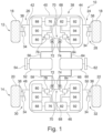
- Figure 1 shows a vehicle 10.
- the vehicle hast a first axle 12 which is a front axle and a second axle 14 which is a rear axle.
- Wheel 20 is a left wheel and wheel 22 is a right wheel.
- the vehicle 10 also comprises a brake system 24.
- the brake system 24 has four brake assemblies 26, 28, 30, 32.
- Brake assembly 26 is configured for selectively braking wheel 16. Consequently, brake assembly 26 is a left brake assembly of the front axle 12.
- Brake assembly 28 is configured for selectively braking wheel 18.
- brake assembly 28 is a right brake assembly of the front axle 12.
- Brake assembly 30 is configured for selectively braking wheel 20.
- Brake assembly 30 is a left brake assembly of the rear axle 14.
- Brake assembly 32 is configured for braking wheel 22. Consequently, brake assembly 32 is a right brake assembly of the rear axle 14.
- each brake assembly 26, 28, 30, 32 comprises a brake disk 34 and a corresponding brake caliper 36 with a brake actuator for selectively engaging the brake disk 34.
- the vehicle 10 additionally comprises a brake control system 38 for controlling the brake system 24.
- the brake control system 38 is coupled to the brake system 24 as will be explained in detail further below.
- the brake control system 38 comprises a first axle control unit 40 being configured for controlling the brake assemblies 26, 28 being associated with the first axle 12, i.e. the front axle 12.
- the first axle control unit 40 is a front axle control unit.
- the first axle control unit 40 can also be called a front electronic control unit (ECU) or a front brake control unit (BCU).
- ECU front electronic control unit
- BCU front brake control unit
- the brake assembly 26, more precisely the corresponding brake caliper 36, is communicatively connected to the first axle control unit 40 via a left front control line 42.
- the brake assembly 28 is communicatively connected to the first axle control unit 40 via a right front control line 44.
- the brake assembly 30, more precisely the corresponding brake caliper 36, is communicatively connected to the second axle control unit 46 via a left rear control line 48.
- the second power supply interface 60 is electrically connected to a second battery unit 62 of the vehicle 10. Consequently, the second battery unit 62 can supply electric energy to the second power supply interface 60.
- first power supply interface 52 and the second power supply interface 60 are structurally separate from one another. Consequently, the first power supply interface 52 and the second power supply interface 60 may be operated independently from one another.
- first battery unit 54 and the second battery unit 62 are separate entities and can be operated independently from one another.
- the first axle control unit 40 comprises a power distribution unit 68 to which the first power supply line 56 and the second power supply line 64 are electrically connected.
- the second power supply line 64 is electrically connected to the power distribution bridge 70 via a second diode 74.
- the right power adjustment element 84 is communicatively connected to a right power control unit 86 such that power being supplied from the power distribution unit 68, more precisely from the power distribution bridge 70, to the right brake assembly control unit 82 can be adjusted using the right power adjustment element 84 and the right power control unit 86.
- all brake assembly control units 76, 82 are operational and thus all brake assemblies 26, 28, 30, 32 can be used for braking the vehicle 10.
Landscapes
- Engineering & Computer Science (AREA)
- Transportation (AREA)
- Mechanical Engineering (AREA)
- Power Engineering (AREA)
- Physics & Mathematics (AREA)
- Electromagnetism (AREA)
- Valves And Accessory Devices For Braking Systems (AREA)
- Braking Systems And Boosters (AREA)
Abstract
Description
- The present disclosure relates to a brake control system for controlling a brake system of a vehicle having at least one axle.
- The disclosure further is directed to a vehicle comprising at least one axle, a brake system having a left brake assembly and a right brake assembly for selectively braking an associated left wheel of the axle and an associated right wheel of the axle, and such a brake control system.
- Additionally, the disclosure relates to a method for operating a brake control system.
- Brake systems and corresponding brake control systems are important safety devices for vehicles. For this reason, it is known to provide the brake systems and the corresponding brake control systems with certain fail operational capabilities. This means that the brake system and the corresponding brake control system stay operational under certain failure conditions. In other words, in case of such a failure condition, the brake system and the corresponding brake control system are still able to brake the corresponding vehicle.
- This aspect is of high relevance for vehicles having a human driver and for partially or fully autonomous vehicles. In partially or fully autonomous vehicles, a situation may occur in which human interaction is not possible or only possible to a certain degree.
- It is an object of the present disclosure to provide a brake control system with improved fail operational capabilities.
- The problem is at least partially solved or alleviated by the subject matter of the independent claims of the present disclosure, wherein further examples are incorporated in the dependent claims.
- According to a first aspect, there is provided a brake control system for controlling a brake system of a vehicle. The vehicle has at least one axle. The brake control system comprises a first power supply interface, a second power supply interface, and at least one axle control unit being configured for controlling brake assemblies being associated with the at least one axle. The first power supply interface is electrically connected to the axle control unit via a first power supply line and the second power supply interface is electrically connected to the axle control unit via a second power supply line. In such a brake control system power can be supplied to the axle control unit via the first power supply interface and the first power supply line or the second power supply interface and the second power supply line. Thus, the power supply of the axle control unit is redundant. It is understood that the first power supply interface and the second power supply interface are configured for providing power to the brake control system independent from one another. In short: the first power supply interface and the second power supply interface are independent from one another. Also the first power supply line and the second power supply line are independent from one another. This means that the first power supply line is separate from the second supply line. Consequently, in a case in which a failure occurs at the first power supply interface or the first power supply line, power can be supplied to the axle control unit via the second power supply interface and the second power supply line. If a failure occurs at the second power supply interface or the second power supply line, power can be supplied to the axle control unit via the first power supply interface and the first power supply line. In both failure conditions, the axle control unit and thus the entire brake control system stays fully operational.
- It is noted that the brake control system according to the present disclosure may be configured for controlling a brake system being a hydraulic brake system. In such a brake system the brake assemblies which are controlled by the brake control system comprise at least one hydraulic actuator being configured for applying a braking force or a braking torque to an associated wheel. Alternatively or additionally, the brake control system according to the present disclosure may be configured for controlling a brake system being an electric, electromechanical or electromagnetic brake system. In such a brake system the brake assemblies which are controlled by the brake control system comprise at least one electric or electromagnetic actuator being configured for applying a braking force or a braking torque to an associated wheel.
- Furthermore, the brake control system according to the present disclosure may be configured for being used in a fully autonomous vehicle, partially autonomous and/or nonautonomous vehicle.
- In an example, the vehicle in which the brake control system according to the present disclosure is used, has two axles.
- In an example, the axle control unit comprises a left brake assembly control unit and a right brake assembly control unit. The left brake assembly control unit is configured for controlling a left brake assembly of the vehicle's axle and the right brake assembly control unit is configured for controlling a right brake assembly of the vehicle's axle. It is understood that the terms "left" and "right" are used for the ease of explanation only. The brake assembly control units could also be designated a first one and a second one. Thus, the axle control unit comprises two separate and independent brake assembly control units, one for each wheel of the corresponding axle. This configuration has the effect that a failure in one of the left brake assembly control unit and the right brake assembly control unit does not affect the respective other.
- In an example, the left brake assembly control unit is communicatively connected to a left motor controller. The right brake assembly control unit is communicatively connected to a right motor controller. Thus, also the motor controllers are independent from one another and may be controlled independently from one another via the left brake assembly control unit and the right brake assembly control unit. Thus, a defect in one of the motor controllers does not affect the respective other motor controller.
- In an example, the left brake assembly control unit is communicatively connected to a left sensor unit. The right brake assembly control unit is communicatively connected to a right sensor unit. The sensor units may be configured for detecting a wheel rotation or a temperature. Moreover, each of the sensor units is configured for providing a detected sensor value to the corresponding brake assembly control unit. Thus, the brake assembly control units can be operated independently from one another.
- In an example, the axle control unit comprises a power distribution unit. The first power supply line and the second power supply line are electrically connected to the power distribution unit. Thus, due to the power distribution unit, power may be supplied to the components of the axle control unit by the first power supply line or the second power supply line. For the components of the axle control unit it does not make a difference whether they receive power via the first power supply line or the second power supply line. The power distribution unit is also configured for excluding a conflict of power supply in cases where both a power supply via the first power supply line and the second power supply line is available.
- In an example, the left brake assembly control unit is electrically connected to the power distribution unit and the right brake assembly control unit is electrically connected to the power distribution unit. Thus, power can be supplied to the left brake assembly control unit and the right brake assembly control unit via the power distribution unit. The power supply is very reliable.
- In an example, the electric connection of the left brake assembly control unit to the power distribution unit comprises a left power adjustment element and the electric connection of the right brake assembly control unit to the power distribution unit comprises a right power adjustment element. Consequently, the power being supplied to the left brake assembly control unit and to the right brake assembly control unit can be adjusted. This is especially important in a situation in which only limited power supply is available. In such a situation, the left power adjustment element and the right power adjustment element may be used for adjusting the power being provided to the left brake assembly control unit and to the right brake assembly control unit such that the limited power supply is respected. This may lead to a reduced functionality of the left brake assembly control unit and/or the right brake assembly control unit. However, it has to be emphasized that both the left brake assembly control unit and the right brake assembly control unit remain operational all the time. The portion of power which is supplied to the left brake assembly control unit and the right brake assembly control unit may change dynamically as a function of a vehicle state or a state of the brake control system. Thus, a maximum of functionality may be guaranteed even in a situation with limited power supply.
- In an example, the left power adjustment element and/or the right power adjustment element comprises a transistor, e.g. a field effect transistor. Consequently, the supplied power may be adjusted in a reliable manner.
- In an example, the brake control system comprises a left power control unit being communicatively connected to the left power adjustment element and a right power control unit being communicatively connected to the right power adjustment element. Thus, the left power control element and the right power control element can be reliably controlled as described hereinabove. It is noted that each of the power control elements is communicatively connected to a separate power control unit. Consequently, the control of the power control elements is independent from one another.
- In an example, the power distribution unit comprises a power distribution bridge being electrically conductive, wherein the left brake assembly control unit and the right brake assembly control unit are electrically connected to opposing ends of the power distribution bridge. Thus, power can be reliably supplied to the left brake assembly control unit and the right brake assembly control unit via the power distribution bridge.
- In an example, the first power supply line and the second power supply line are electrically connected to the power distribution bridge. Thus, power can be supplied to the power distribution bridge by the first power supply line, the second power supply line or both. In other words, the power supply of the power distribution bridge is redundant. This also applies to all elements being electrically connected to the power distribution bridge.
- In an example, the first power supply line is electrically connected to the power distribution bridge via a first diode and the second power supply line is electrically connected to the power distribution bridge via a second diode. As is generally known in the art, diodes have a forward direction along which the diodes are conductive. An electric current is generally not able to pass a diodes in a direction being opposed to the forward direction. Thus, using a diode, undesired currents can be avoided. It is noted that a diode is a passive element, i.e. the functionality of the diode does not rely on power supply. A brake control system having such a configuration is very robust. Errors being caused by currents having an undesired direction are avoided.
- In an example, a forward direction of the diodes is directed along a power supply direction. In this context, a power supply direction is to be understood as a direction from the first power supply interface or the second power supply interface towards the axle control unit. Thus it is avoided that electric current flows from the axle control unit towards one of the power supply interfaces. This is especially useful if one of the power supply interfaces is defective. Reliable power supply of the axle control unit is guaranteed.
- In an example, the brake control system comprises a further axle control unit being configured for controlling brake assemblies being associated with a further axle. The first power supply interface is electrically connected to the further axle control unit via a third power supply line and the second power supply interface is electrically connected to the further axle control unit via a fourth power supply line. Thus, the brake control system is adapted for being used in a vehicle having two axles. The effects and advantages as described above in connection with the axle control unit apply mutatis mutandis to the further axle control unit. It is further understood that all features and explanations which have been provided in connection with the axle control unit hereinabove, also apply to the further axle control unit.
- According to a second aspect, there is provided a vehicle comprising at least one axle. The vehicle additionally comprises a brake system having a left brake assembly and a right brake assembly for selectively braking an associated left wheel of the axle and an associated right wheel of the axle. Moreover, the vehicle comprises a brake control system according to the present disclosure. The brake control system is coupled to the brake system for controlling the brake system. The first power supply interface is electrically connected to a first battery unit and the second power supply interface is electrically connected to a second battery unit. In such a vehicle, the brake system may be controlled in a reliable manner since power may be supplied thereto in a redundant manner using the first power supply interface and the second power supply interface. It is understood that the first battery unit and the second battery unit are independent from one another. Thus, such a vehicle has improved failure operational capabilities. More precisely, if a failure occurs at one of the first power supply interface, the second power supply interface, the first battery unit or the second battery unit, the brake control system remains fully operational. Consequently, all brake assemblies may be used in case of failure. This is an important difference with respect to known brake systems which rely on the concept of using just a portion of brake assemblies in case of power supply failure. It is noted that according to the present disclosure it may be possible that only a limited amount of power is supplied to the brake control units if a power supply failure occurs. However, none thereof will be without power.
- According to a third aspect, there is provided a method for operating a brake control system. The brake control system is configured for controlling a brake system of a vehicle. The brake control system comprises a number of brake assembly control units, a first power supply interface and a second power supply interface. The method comprises:
- powering all brake assembly control units via the second power supply interface if a power supply of the first power supply interface is interrupted, and/or
- powering all brake assembly control units via the first power supply interface if a power supply of the second power supply interface is interrupted.
- The method may be at least partly computer-implemented, and may be implemented in software or in hardware, or in software and hardware. Further, the method may be carried out by computer program instructions running on means that provide data processing functions. The data processing means may be a suitable computing means, such as an electronic control module etc., which may also be a distributed computer system. The data processing means or the computer, respectively, may comprise one or more of a processor, a memory, a data interface, or the like.
- It should be noted that the above examples may be combined with each other irrespective of the aspect involved. Accordingly, the method may be combined with structural features and, likewise, the brake control system and the vehicle may be combined with features described above with regard to the method.
- These and other aspects of the present disclosure will become apparent from and elucidated with reference to the examples described hereinafter.
- Examples of the disclosure will be described in the following with reference to the appended drawings.
- Fig. 1
- shows a vehicle according the present disclosure comprising a brake control system according to the present disclosure being operable by a method according to the present disclosure,
- Fig. 2
- schematically shows the vehicle of
Figure 1 in a first operational situation, - Fig. 3
- schematically shows the vehicle of
Figure 1 in a second operational situation, and - Fig. 4
- schematically shows the vehicle of
Figure 1 in a third operational situation. - The figures are merely schematic representations and serve only to illustrate examples of the disclosure. Identical or equivalent elements are in principle provided with the same reference signs.
-
Figure 1 shows avehicle 10. - The vehicle hast a
first axle 12 which is a front axle and asecond axle 14 which is a rear axle. - On the
first axle 12, twowheels wheel 16 is a left wheel andwheel 18 is a right wheel. - Also on the
rear axle 14 twowheels Wheel 20 is a left wheel andwheel 22 is a right wheel. - The
vehicle 10 also comprises abrake system 24. - The
brake system 24 has fourbrake assemblies -
Brake assembly 26 is configured for selectively brakingwheel 16. Consequently,brake assembly 26 is a left brake assembly of thefront axle 12. -
Brake assembly 28 is configured for selectively brakingwheel 18. Thus,brake assembly 28 is a right brake assembly of thefront axle 12. -
Brake assembly 30 is configured for selectively brakingwheel 20.Brake assembly 30 is a left brake assembly of therear axle 14. -
Brake assembly 32 is configured for brakingwheel 22. Consequently,brake assembly 32 is a right brake assembly of therear axle 14. - In the example shown in the figures, each
brake assembly brake disk 34 and acorresponding brake caliper 36 with a brake actuator for selectively engaging thebrake disk 34. - The
vehicle 10 additionally comprises abrake control system 38 for controlling thebrake system 24. To this end, thebrake control system 38 is coupled to thebrake system 24 as will be explained in detail further below. - The
brake control system 38 comprises a firstaxle control unit 40 being configured for controlling thebrake assemblies first axle 12, i.e. thefront axle 12. - Thus, the first
axle control unit 40 is a front axle control unit. The firstaxle control unit 40 can also be called a front electronic control unit (ECU) or a front brake control unit (BCU). - The
brake assembly 26, more precisely the correspondingbrake caliper 36, is communicatively connected to the firstaxle control unit 40 via a leftfront control line 42. - In the same manner, the
brake assembly 28, more precisely the correspondingbrake caliper 36, is communicatively connected to the firstaxle control unit 40 via a rightfront control line 44. - Furthermore, the
brake control system 38 comprises a secondaxle control unit 46 being configured for controlling thebrake assemblies second axle 14, i.e. therear axle 14. - Consequently, the second
axle control unit 46 is a rear axle control unit. The secondaxle control unit 46 can be designated a rear electronic control unit (ECU) or a rear brake control unit (BCU). - The second
axle control unit 46 may also be designated a furtheraxle control unit 46. In this case, therear axle 14 is afurther axle 14. - The
brake assembly 30, more precisely the correspondingbrake caliper 36, is communicatively connected to the secondaxle control unit 46 via a leftrear control line 48. - In the same manner, the
brake assembly 32, more precisely the correspondingbrake caliper 36, is communicatively connected to the secondaxle control unit 46 via a rightrear control line 50. - The
brake control system 38 comprises a firstpower supply interface 52. - In the example shown, the first
power supply interface 52 of thebrake control system 38 is electrically connected to afirst battery unit 54 of thevehicle 10. Thus, electric energy is provided at the firstpower supply interface 52 by thefirst battery unit 54. - Moreover, the first
power supply interface 52 is electrically connected to the firstaxle control unit 40 via a power supply line being designated a firstpower supply line 56 and electrically connected to the secondaxle control unit 46 via a power supply line being designated a thirdpower supply line 58. - The
brake control system 38 also comprises a secondpower supply interface 60. - The second
power supply interface 60 is electrically connected to asecond battery unit 62 of thevehicle 10. Consequently, thesecond battery unit 62 can supply electric energy to the secondpower supply interface 60. - Additionally, the second
power supply interface 60 is electrically connected to the firstaxle control unit 40 via a power supply line being designated a secondpower supply line 64 and electrically connected to the secondaxle control unit 46 via a power supply line being designated a fourthpower supply line 66. - It is noted that the first
power supply interface 52 and the secondpower supply interface 60 are structurally separate from one another. Consequently, the firstpower supply interface 52 and the secondpower supply interface 60 may be operated independently from one another. - The same applies to the
first battery unit 54 and thesecond battery unit 62. This means that thefirst battery unit 54 and thesecond battery unit 62 are separate entities and can be operated independently from one another. - The first
axle control unit 40 comprises apower distribution unit 68 to which the firstpower supply line 56 and the secondpower supply line 64 are electrically connected. - More precisely, the
power distribution unit 68 comprises apower distribution bridge 70 being electrically conductive. - The first
power supply line 56 is electrically connected to thepower distribution bridge 70 via afirst diode 72. - The second
power supply line 64 is electrically connected to thepower distribution bridge 70 via asecond diode 74. - A forward direction of both the
first diode 72 and thesecond diode 74 is directed along a power supply direction, i.e. along a direction from the respective firstpower supply interface 52 or secondpower supply interface 60 towards thepower distribution bridge 70. - Consequently, due to the
diodes power supply interface 52 and/or the secondpower supply interface 60 towards thepower distribution bridge 70, but not in the opposite direction. - A left brake
assembly control unit 76 is electrically connected to a first, left end of thepower distribution bridge 70 via a leftpower adjustment element 78. - The left
power adjustment element 78 is communicatively connected to a leftpower control unit 80 such that power being supplied from thepower distribution unit 68, more precisely from thepower distribution bridge 70, to the left brakeassembly control unit 76 can be adjusted using the leftpower adjustment element 78 and the leftpower control unit 80. - In the same manner, a right brake
assembly control unit 82 is electrically connected to a second, right end of thepower distribution bridge 70 via a rightpower adjustment element 84. - The right
power adjustment element 84 is communicatively connected to a rightpower control unit 86 such that power being supplied from thepower distribution unit 68, more precisely from thepower distribution bridge 70, to the right brakeassembly control unit 82 can be adjusted using the rightpower adjustment element 84 and the rightpower control unit 86. - The left brake
assembly control unit 76 of the firstaxle control unit 40 is configured for controlling theleft brake assembly 26. - To this end, the left brake
assembly control unit 76 is communicatively connected to aleft motor controller 88 being configured for controlling the operation of thebrake caliper 36 of theleft brake assembly 26 of thefront axle 12. - For the same purpose, the left brake
assembly control unit 76 is communicatively connected to aleft sensor unit 90. - Thus, the
left brake assembly 26 can be controlled according to the principles of closed loop control. - The right brake
assembly control unit 82 of the firstaxle control unit 40 is configured for controlling theright brake assembly 28. - To this end, the right brake
assembly control unit 82 is communicatively connected to aright motor controller 92 being configured for controlling the operation of thebrake caliper 36 of theright brake assembly 28 of thefront axle 12. - For the same purpose, the right brake
assembly control unit 82 is communicatively connected to aright sensor unit 94. - Thus, also the
right brake assembly 28 can be controlled according to the principles of closed loop control. - The second
axle control unit 46 is structurally identical to the firstaxle control unit 40. In contrast to the firstaxle control unit 40, the thirdpower supply line 58 and the fourthpower supply line 66 are connected to thepower distribution unit 68. Moreover, the secondaxle control unit 46 is configured for controlling theleft brake assembly 30 and theright brake assembly 32. - Beyond that, reference is made to the above explanations. It is noted that in connection with the second
axle control unit 46 the same reference signs are used as in connection with the firstaxle control unit 40. - The
brake control system 38 may be operated in accordance with a method for operating abrake control system 38 and the associatedvehicle 10. - In order to explain this method,
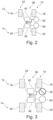
Figures 2 to 4 show three exemplary operational situations of thebrake control system 38. -
Figure 2 shows an operational situation in which no error or failure has occurred. In this situation, thebrake control system 38 can be powered via the firstpower supply interface 52 and the secondpower supply interface 60. If high power is needed, both power supply interfaces 52, 60 can be used at the same time. If comparatively little power is needed, it is also possible to use just one of the power supply interfaces 52, 60 for powering thebrake control system 38. -
Figure 3 shows a situation in which a failure has occurred which leads to the fact that the firstpower supply interface 52 cannot be used for powering thebrake control system 38. In other words, power supply via the firstpower supply interface 52 is interrupted. Due to the electric connections of the power supply interfaces 52, 60 as has been explained above, all brakeassembly control units power supply interface 60. -
Figure 4 shows a situation in which a failure has occurred which leads to the fact that the secondpower supply interface 60 cannot be used for powering thebrake control system 38. In other words, power supply via the secondpower supply interface 60 is interrupted. Due to the electric connections of the power supply interfaces 52, 60 as has been explained above, all brakeassembly control units power supply interface 52. - Thus, also in situation of interrupted power supply, all brake
assembly control units brake assemblies vehicle 10. - It is noted that in case of a power interruption at one of the power supply interfaces 52, 60 in combination with a very high power demand, a situation may occur in which the total power demand cannot be satisfied. However, the
power adjustment elements assembly control units assembly control units - Other variations to the disclosed examples can be understood and effected by those skilled in the art in practicing the claimed disclosure, from the study of the drawings, the disclosure, and the appended claims. In the claims the word "comprising" does not exclude other elements or steps and the indefinite article "a" or "an" does not exclude a plurality. A single processor or other unit may fulfill the functions of several items or steps recited in the claims. The mere fact that certain measures are recited in mutually different dependent claims does not indicate that a combination of these measures cannot be used to advantage. Any reference signs in the claims should not be construed as limiting the scope of the claims.
-
- 10
- vehicle
- 12
- first axle, front axle
- 14
- second axle, rear axle
- 16
- left wheel of the first axle
- 18
- right wheel of the first axle
- 20
- left wheel of the second axle
- 22
- right wheel of the second axle
- 24
- brake system
- 26
- left brake assembly of the first axle
- 28
- right brake assembly of the first axle
- 30
- left brake assembly of the second axle
- 32
- right brake assembly of the second axle
- 34
- brake disk
- 36
- brake caliper
- 38
- brake control system
- 40
- first axle control unit
- 42
- left front control line
- 44
- right front control line
- 46
- second axle control unit
- 48
- left rear control line
- 50
- right rear control line
- 52
- first power supply interface
- 54
- first battery unit
- 56
- first power supply line
- 58
- third power supply line
- 60
- second power supply interface
- 62
- second battery unit
- 64
- second power supply line
- 66
- fourth power supply line
- 68
- power distribution unit
- 70
- power distribution bridge
- 72
- first diode
- 74
- second diode
- 76
- left brake assembly control unit
- 78
- left power adjustment element
- 80
- left power control unit
- 82
- right brake assembly control unit
- 84
- right power adjustment element
- 86
- right power control unit
- 88
- left motor controller
- 90
- left sensor unit
- 92
- right motor controller
- 94
- right sensor unit
Claims (15)
- Brake control system (38) for controlling a brake system (24) of a vehicle (10) having at least one axle (12), the brake control system (38) comprising a first power supply interface (52), a second power supply interface (60), and at least one axle control unit (40) being configured for controlling brake assemblies (26, 28) being associated with the at least one axle (12),
the first power supply interface (52) being electrically connected to the axle control unit (40) via a first power supply line (56) and the second power supply interface (60) being electrically connected to the axle control unit (40) via a second power supply line (64). - The brake control system (38) according to claim 1, wherein the axle control unit (40) comprises a left brake assembly control unit (76) and a right brake assembly control unit (82).
- The brake control system (38) according to claim 2, wherein the left brake assembly control unit (76) is communicatively connected to a left motor controller (88) and wherein the right brake assembly control unit (82) is communicatively connected to a right motor controller (92).
- The brake control system (38) according to claim 2 or 3, wherein the left brake assembly control unit (76) is communicatively connected to a left sensor unit (90) and wherein the right brake assembly control unit (82) is communicatively connected to a right sensor unit (94).
- The brake control system (38) according to any one of the preceding claims, wherein the axle control unit (40) comprises a power distribution unit (68) and the first power supply line (56) and the second power supply line (64) are electrically connected to the power distribution unit (68).
- The brake control system (38) according to any one of claims 2 to 4 and claim 5, wherein the left brake assembly control unit (76) is electrically connected to the power distribution unit (68) and the right brake assembly control unit (82) is electrically connected to the power distribution unit (68).
- The brake control system (38) according to claim 6, wherein the electric connection of the left brake assembly control unit (76) to the power distribution unit (68) comprises a left power adjustment element (78) and wherein the electric connection of the right brake assembly control unit (82) to the power distribution unit (68) comprises a right power adjustment element (84).
- The brake control system (38) according to claim 7, comprising a left power control unit (80) being communicatively connected to the left power adjustment element (78) and a right power control unit (86) being communicatively connected to the right power adjustment element (84).
- The brake control system (38) according to any one of claims 6 to 8 wherein the power distribution unit (68) comprises a power distribution bridge (70) being electrically conductive, wherein the left brake assembly control unit (76) and the right brake assembly control unit (82) are electrically connected to opposing ends of the power distribution bridge (70).
- The brake control system (38) according to claim 9, wherein the first power supply line (56) and the second power supply line (64) are electrically connected to the power distribution bridge (70).
- The brake control system (38) according to claim 10, wherein the first power supply line (56) is electrically connected to the power distribution bridge (70) via a first diode (72) and the second power supply line (64) is electrically connected to the power distribution bridge (70) via a second diode (74).
- The brake control system (38) according to claim 11, wherein a forward direction of the diodes (72, 74) is directed along a power supply direction.
- The brake control system (38) according to any one of the preceding claims, comprising a further axle control unit (46) being configured for controlling brake assemblies (30, 32) being associated with a further axle (14), the first power supply interface (52) being electrically connected to the further axle control unit (46) via a third power supply line (58) and the second power supply interface (60) being electrically connected to the further axle control unit (46) via a fourth power supply line (66).
- A vehicle (10) comprising at least one axle (12, 14), a brake system (24) having a left brake assembly (26, 30) and a right brake assembly (28, 32) for selectively braking an associated left wheel (16, 20) of the axle (12, 14) and an associated right wheel (18, 22) of the axle (12, 14), and a brake control system (38) according to any one of the preceding claims being coupled to the brake system (24) for controlling the brake system (24), the first power supply interface (52) being electrically connected to a first battery unit (54) and the second power supply interface (60) being electrically connected to a second battery unit (62).
- A method for operating a brake control system (38) for controlling a brake system (24) of a vehicle (10), wherein the brake control system (38) comprises a number of brake assembly control units (76, 82), a first power supply interface (52) and a second power supply interface (60), comprising:- powering all brake assembly control units (76, 82) via the second power supply interface (60) if a power supply of the first power supply interface (52) is interrupted, and/or- powering all brake assembly control units (76, 82) via the first power supply interface (52) if a power supply of the second power supply interface (60) is interrupted.
Priority Applications (3)
| Application Number | Priority Date | Filing Date | Title |
|---|---|---|---|
| EP22150313.9A EP4209399A1 (en) | 2022-01-05 | 2022-01-05 | Brake control system for controlling a brake system, vehicle and method for operating a brake control system |
| US18/147,920 US20230211673A1 (en) | 2022-01-05 | 2022-12-29 | Brake control system for controlling a brake system, vehicle and method for operating a brake control system |
| CN202310008236.9A CN116394898A (en) | 2022-01-05 | 2023-01-04 | Brake control system for controlling a brake system, method of operating same and vehicle |
Applications Claiming Priority (1)
| Application Number | Priority Date | Filing Date | Title |
|---|---|---|---|
| EP22150313.9A EP4209399A1 (en) | 2022-01-05 | 2022-01-05 | Brake control system for controlling a brake system, vehicle and method for operating a brake control system |
Publications (1)
| Publication Number | Publication Date |
|---|---|
| EP4209399A1 true EP4209399A1 (en) | 2023-07-12 |
Family
ID=79230881
Family Applications (1)
| Application Number | Title | Priority Date | Filing Date |
|---|---|---|---|
| EP22150313.9A Withdrawn EP4209399A1 (en) | 2022-01-05 | 2022-01-05 | Brake control system for controlling a brake system, vehicle and method for operating a brake control system |
Country Status (3)
| Country | Link |
|---|---|
| US (1) | US20230211673A1 (en) |
| EP (1) | EP4209399A1 (en) |
| CN (1) | CN116394898A (en) |
Families Citing this family (1)
| Publication number | Priority date | Publication date | Assignee | Title |
|---|---|---|---|---|
| KR20230167773A (en) * | 2022-06-02 | 2023-12-12 | 현대모비스 주식회사 | Brake Apparatus For Vehicle |
Citations (6)
| Publication number | Priority date | Publication date | Assignee | Title |
|---|---|---|---|---|
| US20030233179A1 (en) * | 2002-06-14 | 2003-12-18 | Kenichiro Matsubara | Electrically driven brake device and control apparatus thereof |
| US20050200194A1 (en) * | 2003-09-29 | 2005-09-15 | Haldex Brake Products Ab | Power supply network for brake system |
| US20080296106A1 (en) * | 2007-05-30 | 2008-12-04 | Peter Nilsson | Redundant Brake Actuators For Fail Safe Brake System |
| US20170210361A1 (en) * | 2015-07-02 | 2017-07-27 | Mitsubishi Jidosha Kogyo Kabushiki Kaisha | Electric brake device |
| EP3339119A1 (en) * | 2016-12-22 | 2018-06-27 | Haldex Brake Products Aktiebolag | Electric brake system for a vehicle |
| US20200254988A1 (en) * | 2017-09-21 | 2020-08-13 | Freni Brembo S.P.A. | Brake by wire braking system for vehicles, provided with electric actuation and electric back-up |
Family Cites Families (4)
| Publication number | Priority date | Publication date | Assignee | Title |
|---|---|---|---|---|
| DE102016012617A1 (en) * | 2016-10-20 | 2018-04-26 | Lucas Automotive Gmbh | System with separate control units for the actuators of an electric parking brake |
| JP7156008B2 (en) * | 2018-12-26 | 2022-10-19 | トヨタ自動車株式会社 | parking assist device |
| CN113002511B (en) * | 2019-12-21 | 2022-09-09 | 瀚德万安(上海)电控制动系统有限公司 | An electromechanical braking system |
| CN113696731B (en) * | 2021-09-01 | 2024-03-08 | 中汽创智科技有限公司 | Redundant power supply system for braking system, redundant power supply control method and vehicle |
-
2022
- 2022-01-05 EP EP22150313.9A patent/EP4209399A1/en not_active Withdrawn
- 2022-12-29 US US18/147,920 patent/US20230211673A1/en not_active Abandoned
-
2023
- 2023-01-04 CN CN202310008236.9A patent/CN116394898A/en active Pending
Patent Citations (6)
| Publication number | Priority date | Publication date | Assignee | Title |
|---|---|---|---|---|
| US20030233179A1 (en) * | 2002-06-14 | 2003-12-18 | Kenichiro Matsubara | Electrically driven brake device and control apparatus thereof |
| US20050200194A1 (en) * | 2003-09-29 | 2005-09-15 | Haldex Brake Products Ab | Power supply network for brake system |
| US20080296106A1 (en) * | 2007-05-30 | 2008-12-04 | Peter Nilsson | Redundant Brake Actuators For Fail Safe Brake System |
| US20170210361A1 (en) * | 2015-07-02 | 2017-07-27 | Mitsubishi Jidosha Kogyo Kabushiki Kaisha | Electric brake device |
| EP3339119A1 (en) * | 2016-12-22 | 2018-06-27 | Haldex Brake Products Aktiebolag | Electric brake system for a vehicle |
| US20200254988A1 (en) * | 2017-09-21 | 2020-08-13 | Freni Brembo S.P.A. | Brake by wire braking system for vehicles, provided with electric actuation and electric back-up |
Also Published As
| Publication number | Publication date |
|---|---|
| US20230211673A1 (en) | 2023-07-06 |
| CN116394898A (en) | 2023-07-07 |
Similar Documents
| Publication | Publication Date | Title |
|---|---|---|
| US6317675B1 (en) | Electromechanical brake system | |
| EP3623242B1 (en) | A system and a method for controlling an electric vehicle | |
| US20220340118A1 (en) | Braking system for a vehicle | |
| US20030006726A1 (en) | Electrical brake system | |
| CN112061104B (en) | Brake control system | |
| GB2316726A (en) | Electronic brake system | |
| US20210162971A1 (en) | Brake system for a motor vehicle | |
| US12351142B2 (en) | Sensor assembly for a vehicle and multi-circuit braking system having redundant control and rotation rate information communication | |
| JP2011131879A (en) | Asymmetric electric brake mechanism for aircraft | |
| JP2000085556A (en) | System relating to safety, especially electromechanical brake system | |
| CN110799394B (en) | Vehicle brake system | |
| US20230211673A1 (en) | Brake control system for controlling a brake system, vehicle and method for operating a brake control system | |
| JP7239709B2 (en) | CONTROL ARCHITECTURE FOR ELECTRIC BRAKE AND STEERING OF VEHICLE AND CONTROL METHOD OF THE CONTROL ARCHITECTURE | |
| US11511689B2 (en) | Supplementary power supply and a method for providing supplemental power | |
| CN109649486B (en) | Steering control system of a steering system of a motor vehicle and method for operating the same | |
| US20250269831A1 (en) | Brake system and method for operating a brake system | |
| US20250368175A1 (en) | Single electric brake booster module with redundant electronics | |
| JP7250601B2 (en) | vehicle control system | |
| CN111532251A (en) | Braking system applied to unmanned vehicle | |
| CN212313519U (en) | Braking system applied to unmanned vehicle | |
| EP4491467B1 (en) | Control system configured for controlling steering and braking of a vehicle | |
| US20250115287A1 (en) | Steering System and Method for Operating a Steering System | |
| US20250326387A1 (en) | Brake control unit having redundant power supply | |
| KR20250174496A (en) | Power supply system including power distribution device | |
| CN120039233A (en) | Parking method, vehicle and storage medium |
Legal Events
| Date | Code | Title | Description |
|---|---|---|---|
| PUAI | Public reference made under article 153(3) epc to a published international application that has entered the european phase |
Free format text: ORIGINAL CODE: 0009012 |
|
| STAA | Information on the status of an ep patent application or granted ep patent |
Free format text: STATUS: REQUEST FOR EXAMINATION WAS MADE |
|
| 17P | Request for examination filed |
Effective date: 20221116 |
|
| AK | Designated contracting states |
Kind code of ref document: A1 Designated state(s): AL AT BE BG CH CY CZ DE DK EE ES FI FR GB GR HR HU IE IS IT LI LT LU LV MC MK MT NL NO PL PT RO RS SE SI SK SM TR |
|
| STAA | Information on the status of an ep patent application or granted ep patent |
Free format text: STATUS: EXAMINATION IS IN PROGRESS |
|
| 17Q | First examination report despatched |
Effective date: 20231211 |
|
| STAA | Information on the status of an ep patent application or granted ep patent |
Free format text: STATUS: THE APPLICATION IS DEEMED TO BE WITHDRAWN |
|
| 18D | Application deemed to be withdrawn |
Effective date: 20250617 |