EP4209362A1 - Tire - Google Patents
Tire Download PDFInfo
- Publication number
- EP4209362A1 EP4209362A1 EP21864344.3A EP21864344A EP4209362A1 EP 4209362 A1 EP4209362 A1 EP 4209362A1 EP 21864344 A EP21864344 A EP 21864344A EP 4209362 A1 EP4209362 A1 EP 4209362A1
- Authority
- EP
- European Patent Office
- Prior art keywords
- sipe
- tire
- piece
- sipe piece
- closed
- Prior art date
- Legal status (The legal status is an assumption and is not a legal conclusion. Google has not performed a legal analysis and makes no representation as to the accuracy of the status listed.)
- Granted
Links
Images







Classifications
-
- B—PERFORMING OPERATIONS; TRANSPORTING
- B60—VEHICLES IN GENERAL
- B60C—VEHICLE TYRES; TYRE INFLATION; TYRE CHANGING; CONNECTING VALVES TO INFLATABLE ELASTIC BODIES IN GENERAL; DEVICES OR ARRANGEMENTS RELATED TO TYRES
- B60C11/00—Tyre tread bands; Tread patterns; Anti-skid inserts
- B60C11/03—Tread patterns
- B60C11/12—Tread patterns characterised by the use of narrow slits or incisions, e.g. sipes
- B60C11/1236—Tread patterns characterised by the use of narrow slits or incisions, e.g. sipes with special arrangements in the tread pattern
-
- B—PERFORMING OPERATIONS; TRANSPORTING
- B60—VEHICLES IN GENERAL
- B60C—VEHICLE TYRES; TYRE INFLATION; TYRE CHANGING; CONNECTING VALVES TO INFLATABLE ELASTIC BODIES IN GENERAL; DEVICES OR ARRANGEMENTS RELATED TO TYRES
- B60C11/00—Tyre tread bands; Tread patterns; Anti-skid inserts
- B60C11/03—Tread patterns
- B60C11/12—Tread patterns characterised by the use of narrow slits or incisions, e.g. sipes
- B60C11/1204—Tread patterns characterised by the use of narrow slits or incisions, e.g. sipes with special shape of the sipe
- B60C11/1218—Three-dimensional shape with regard to depth and extending direction
-
- B—PERFORMING OPERATIONS; TRANSPORTING
- B60—VEHICLES IN GENERAL
- B60C—VEHICLE TYRES; TYRE INFLATION; TYRE CHANGING; CONNECTING VALVES TO INFLATABLE ELASTIC BODIES IN GENERAL; DEVICES OR ARRANGEMENTS RELATED TO TYRES
- B60C11/00—Tyre tread bands; Tread patterns; Anti-skid inserts
- B60C11/03—Tread patterns
- B60C11/12—Tread patterns characterised by the use of narrow slits or incisions, e.g. sipes
- B60C11/1259—Depth of the sipe
- B60C11/1263—Depth of the sipe different within the same sipe
-
- B—PERFORMING OPERATIONS; TRANSPORTING
- B60—VEHICLES IN GENERAL
- B60C—VEHICLE TYRES; TYRE INFLATION; TYRE CHANGING; CONNECTING VALVES TO INFLATABLE ELASTIC BODIES IN GENERAL; DEVICES OR ARRANGEMENTS RELATED TO TYRES
- B60C11/00—Tyre tread bands; Tread patterns; Anti-skid inserts
- B60C11/03—Tread patterns
- B60C11/12—Tread patterns characterised by the use of narrow slits or incisions, e.g. sipes
- B60C11/1204—Tread patterns characterised by the use of narrow slits or incisions, e.g. sipes with special shape of the sipe
- B60C2011/1213—Tread patterns characterised by the use of narrow slits or incisions, e.g. sipes with special shape of the sipe sinusoidal or zigzag at the tread surface
-
- B—PERFORMING OPERATIONS; TRANSPORTING
- B60—VEHICLES IN GENERAL
- B60C—VEHICLE TYRES; TYRE INFLATION; TYRE CHANGING; CONNECTING VALVES TO INFLATABLE ELASTIC BODIES IN GENERAL; DEVICES OR ARRANGEMENTS RELATED TO TYRES
- B60C11/00—Tyre tread bands; Tread patterns; Anti-skid inserts
- B60C11/03—Tread patterns
- B60C11/12—Tread patterns characterised by the use of narrow slits or incisions, e.g. sipes
- B60C11/1236—Tread patterns characterised by the use of narrow slits or incisions, e.g. sipes with special arrangements in the tread pattern
- B60C2011/1254—Tread patterns characterised by the use of narrow slits or incisions, e.g. sipes with special arrangements in the tread pattern with closed sipe, i.e. not extending to a groove
Definitions
- the present disclosure relates to a tire.
- Patent Document 1 Japanese Patent Application Publication No. 2003-025812
- the land portions of the tread portion are provided with a plurality of sipes extending in the tire axial direction and arranged in the tire circumferential direction.
- sipes including a component extending in the tire circumferential direction are arranged.
- the number of the sipes which can be arranged per unit length in the tire circumferential direction of the land portion tends to decrease. Therefore, there is a possibility that the braking/driving performance on ice will be impaired.
- a main problem is to provide a tire improved in braking/driving performance and turning performance on ice.
- the present disclosure is a tire including a tread portion, wherein
- FIG. 1 shows a cross-sectional view of a tread portion 2 of a tire 1 of the present embodiment.
- FIG. 1 is a meridian cross sectional view including the tire rotation axis, of the tire 1 under a normal state.
- the tire 1 of the present embodiment is suitably used as, for example, a pneumatic tire for passenger cars. However, it is not limited to such an embodiment, and the tire 1 of the present disclosure may be used for heavy loads, for example.
- the "normal state” is a state in which the tire mounted on a regular rim is inflated to a regular internal pressure but loaded with no load.
- the normal state means a standard usage state corresponding to the purpose of use of the tire and a no-load state.
- dimensions and the like of various parts of the tire are the values measured under the normal state. ⁇ ach of the configurations described in this specification shall allow for normal errors involved in rubber molded products.
- the "regular rim” is a rim defined for each tire by a standard in a standard system including the standard on which the tire is based, for example, "standard Rim” in JATMA, "Design Rim” in TRA, and “Measuring Rim” in ETRTO,
- the "regular internal pressure” is air pressure defined for each tire by a standard in a standard system including the standard on which the tire is based, for example, “MAXIMUM AIR PRESSURE” in JATMA, the maximum value listed in the table “TIRE LOAD LIMITS AT VARIOUS COLD INFLATION PRESSURES" in TRA, "INFLATION PRESSURE” in ETRTO.
- the tread portion 2 is provided with, for example, a plurality of main grooves 3 continuously extending in the tire circumferential direction, and a plurality of land portions 4 divided thereby.
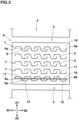
- FIG. 2 shows an enlarged plan view of the land portion 4.
- the land portion 4 of the present embodiment is configured, for example, as a row of blocks including a plurality of blocks 6 in the tire circumferential direction.
- the blocks 6 are defined between a plurality of lateral grooves 5 crossing the land portion 4 in the tire axial direction.
- the land portion 4 of the present disclosure is not limited to such an example, and may be a rib continuously extending in the tire circumferential direction, for example.
- a plurality of closed sipes 8 are arranged in the tire axial direction.
- a plurality of sipe groups 7 each made up of a plurality of closed sipes 8 is disposed in one block 6.
- one sipe group 7 is made up of 3 to 7 closed sipes 8.
- the "sipe” is a slit having a minute width, and refers to that having a width of 1.5 mm or less between two sipe walls facing each other.
- the above-said width of the closed sipe 8 of the present embodiment is 1.0 mm or less.
- the term "closed sipe” refers to a sipe whose both ends are terminated within the land portion 4.
- the sipe group 7 provided in the block 6 of the present embodiment consists of the closed sipes 8 only. In other words, none of the sipes are connected to the edges of the block 6.
- the present invention is however, not limited to such a mode, and the sipe arranged near the edge of the block 6 may be a non-closed sipe having one end opened at the edge.
- each closed sipe 8 comprises a first end 8a and a second end 8b, and a first sipe piece 11, a second sipe piece 12 and a third sipe piece 13.
- the first end 8a is the end of the closed sipe 8 on the first side B1 in the tire axial direction.
- the second end 8b is the end of the closed sipe 8 on the second side B2 in the tire axial direction.
- the first sipe piece 11 extends in the tire axial direction on the first end 8a side of the third sipe piece 13.
- the second sipe piece 12 extends in the tire axial direction on the second end 8b side of the third sipe piece 13.
- the third sipe piece 13 is inclined with respect to the tire axial direction.
- the first sipe piece 11 is positioned on the first side A1 in the tire circumferential direction and on the first side B1 in the tire axial direction of the second sipe piece 12.
- the first sipe piece 11 continues to the third sipe piece 13 om the first side A1 in the tire circumferential direction.
- the second sipe piece 12 continues to the third sipe piece 13 on the second side A2 in the tire circumferential direction.
- the closed sipes 8 arranged in the tire axial direction overlap each other in the tire axial direction and the tire circumferential direction.
- the expression “the closed sipes 8 overlap each other in the tire axial direction” means such a mode that a virtual region obtained by extending one closed sipe 8 parallel to the tire circumferential direction overlaps with the closed sipe 8 adjacent thereto.
- the expression “the closed sipes 8 overlap each other in the tire circumferential direction” means such a mode that a virtual region obtained by extending one closed sipe 8 in parallel with the tire axial direction overlaps the closed sipe 8 adjacent thereto.
- the sipe group 7 of the present disclosure includes a plurality of closed sipes 8 arranged in the tire axial direction. Since the closed sipes 8 are difficult to open during braking and driving, they are less likely to be clogged with snow or ice inside, and the edge effect can be stably exhibited over a long period of time. Thus, the anti-snow clogging performance when running on snow is improved. In addition, the closed sipes 8 increase the pattern rigidity of the land portion 4 and enhance the steering stability on dry road surfaces.
- the third sipe piece 13 is inclined with respect to the tire axial direction, it exerts a frictional force in the tire axial direction on ice, thereby capable of improving turning performance on ice. Furthermore, since the second sipe piece 12 of the closed sipe 8 overlaps the first sipe piece 11 of the closed sipe 8 adjacent in the tire axial direction and the tire circumferential direction, it is possible to provide many closed sipes 8 in the land portion 4, and excellent braking/driving performance can be exhibited on ice.
- the present disclosure is however, not limited to such a mode.
- the sipe group 7 of the present embodiment extends along the tire axial direction, but may extend with a certain degree of inclination with respect to the tire axial direction.
- an virtual straight line 18 (indicated by a two-dot chain line), which connecting between a first end 8a of the closed sipe 8 provided at the end on the first side B1 in the tire axial direction, and a first end 8b of the closed sipe 8 provided at the end on the second side B2 in the tire axial direction, is, for example, 45 degrees or less, preferably 15 degrees or less, and more preferably 5 degrees or less with respect to the tire axial direction.
- the sipe group 7 is however, not limited to such a mode, and can be changed according to the shape of the land portion, and as described later, for example, the virtual straight line 18 may extend obliquely.
- the first end 8a of each closed sipe 8 is placed in the same imaginary zone 15 (colored in FIG. 2 ) extending parallel to the tire axial direction with a minute width.
- the width of the imaginary zone 15 is, for example, 3.0 mm or less.
- the first ends 8a of the respective closed sipes 8 are placed on a same virtual straight line extending parallel to the tire axial direction.
- the second end 8b of each closed sipe 8 is placed in the same imaginary zone (not shown) extending parallel to the tire axial direction with a minute width.
- the width of the imaginary zone is, for example, 3.0 mm or less.
- the second ends 8b of the respective closed sipes 8 are placed on a same virtual straight line extending parallel to the tire axial direction.
- the overlapping length L2 of two closed sipes 8 adjacent to each other in the tire axial direction is 10% to 40% of the maximum length L1 in the tire axial direction of the closed sipe 8.
- excellent braking/driving performance is exhibited while maintaining the wear resistance of the land portion 4.
- the overlapping length L2 is less than 10% of the length L1, the edge component in the tire axial direction disposed on the land portion 4 is reduced, and the braking/driving performance on ice may deteriorate.
- the overlapping length L2 exceeds 40% of the length L1, the clearance between two closed sipes 8 adjacent to each other becomes narrow, which may cause uneven wear of the land portion.
- ⁇ ach length of the sipe is measured at the widthwise center line of the sipe.
- the distance L3 in the tire circumferential direction between the second end 8b of one closed sipe 8 and the first end 8a of the closed sipe 8 adjacent thereto is, for example, not more than 10%, preferably not more than 5% of the length L6 in the tire circumferential direction the third sipe piece 13.
- the second end 8b is positioned on the first side A1 in the tire circumferential direction than the first end 8a.
- the first end 8a and the second end 8b are located on the second side A2 in the tire circumferential direction of the first sipe piece 11, and on the first side A1 in the tire circumferential direction of the second sipe piece 12.
- the first end 8a and the second end 8b are located within a region (not shown) formed by extending the third sipe piece 13 toward both sides in the tire axial direction in parallel with the tire axial direction.
- the closed sipe 8 of the present embodiment includes a first outer sipe piece 16 and a second outer sipe piece 17.
- the first outer sipe piece 16 extends from the first end 8a to the first sipe piece 11.
- the second outer sipe piece 17 extends from the second end 8b to the second sipe piece 12.
- Such closed sipe 8 provides a large frictional force in the tire axial direction by means of the first outer sipe piece 16 and the second outer sipe piece 17, thereby enhancing turning performance on ice.
- the angle between the first sipe piece 11 and the first outer sipe piece 16 and the angle between the second sipe piece 12 and the second outer sipe piece are each, for example, not less than 80 degrees, preferably not less than 90 degrees. In the present embodiment, the above two angles are 100 to 120 degrees.
- each of the sipe pieces of the closed sipe 8 extends linearly.
- each of the sipe pieces may extend in a curved manner.
- each of the axial length L4 of the first sipe piece 11 and the axial length L5 of the second sipe piece 12 is greater than the axial length of the third sipe piece 13.
- Each of the length L4 of the first sipe piece 11 and the length L5 of the second sipe piece 12 is 35% to 45% of the axial length L1 of the closed sipe 8.
- the angle of the first sipe piece 11 with respect to the tire axial direction and the angle of the second sipe piece 12 with respect to the tire axial direction are, for example, in a range of +/-20 degrees, preferably in a range of +/-10 degrees. ⁇ ach of the first sipe piece 11 and the second sipe piece 12 of the present embodiment extends parallel to the tire axial direction. Such first sipe piece 11 and second sipe piece 12 help to effectively enhance the braking/driving performance on ice.
- the first sipe pieces 11 of the closed sipes 8 are arranged in a same imaginary zone (not shown) extending parallel to the tire axial direction with a minute width.
- the width of the imaginary zone is, for example, 3.0 mm or less.
- the first sipe pieces 11 of the closed sipes 8 are arranged on a same virtual straight line extending parallel to the tire axial direction. Thereby, the braking/driving performance is improved while maintaining the uneven wear resistance performance.
- the second sipe pieces 12 of the closed sipes 8 are arranged in a same imaginary zone (not shown) extending parallel to the tire axial direction with a minute width.
- the width of the imaginary zone is, for example, 3.0 mm or less.
- the second sipe pieces 12 of the closed sipes 8 are arranged on a same virtual straight line extending parallel to the tire axial direction.
- the length L6 in the tire circumferential direction of the third sipe piece 13 is, for example, smaller than the length L1 in the tire axial direction of the closed sipe 8.
- the length L6 of the third sipe piece 13 is smaller than the length L4 in the tire axial direction of the first sipe piece 11 and the length L5 in the tire axial direction of the second sipe piece 12.
- the length L6 of the third sipe piece 13 is 25% to 40% of the length L1 of the closed sipe 8.
- Such third sipe piece 13 enhances turning performance on ice while maintaining uneven wear resistance performance.
- the third sipe piece 13 for example, is inclined to the second side A2 in the tire circumferential direction from the first sipe piece 11 toward the second side B2 in the tire axial direction.
- the third sipe piece 13 is arranged at a larger angle with respect to the tire axial direction than the first sipe piece 11 and the second sipe piece 12.
- the third sipe piece 13 may, for example, extend parallel to the tire circumferential direction.
- the angle of the third sipe piece 13 of the present embodiment with respect to the tire axial direction is, for example, not less than 45 degrees, preferably 60 to 80 degrees. Such third sipe piece 13 improves turning performance on ice, while providing frictional force in the tire circumferential direction too.
- the closed sipes 8 of the present embodiment are arranged so that the third sipe pieces 13 become parallel to each other. Thereby, the uneven wear resistance of the land portion 4 and the steering stability on dry road surfaces are improved.
- the length L7 in the tire circumferential direction of the first outer sipe piece 16 and the length L8 in the tire circumferential direction of the second outer sipe piece 17 are, for example, smaller than the length in the tire circumferential direction of the third sipe piece 13.
- the length L7 of the first outer sipe piece 16 and the length L8 of the second outer sipe piece 17 are preferably not more than 60%, more preferably 45% to 55% of the length L6 of the third sipe piece 13. This ensures a sufficient clearance between two closed sipes 8 adjacent to each other. Therefore, uneven wear resistance is maintained, and demoldability during vulcanization molding is ensured.
- the first outer sipe piece 16 and the second outer sipe piece 17 are each inclined in a direction opposite to the third sipe piece 13.
- the angle of the first outer sipe piece 16 with respect to the tire circumferential direction and the angle of the second outer sipe piece 17 with respect to the tire circumferential direction are each, for example, not more than 45 degrees, preferably 10 to 30 degrees.
- the angle of the first outer sipe piece 16 and the angle of the second outer sipe piece 17 are the same as the angle of the third sipe piece 13 with respect to the tire circumferential direction.
- the first outer sipe piece 16 and the second outer sipe piece 17 may extend parallel to the tire circumferential direction, for example.
- the second sipe piece 12 of the closed sipe 8 on one side overlaps in the tire axial direction with the first sipe piece 11 of the closed sipe 8 on the other side.
- the second outer sipe piece 17 of the closed sipe 8 on one side extends from the second sipe piece 12 toward the first side A1 in the tire circumferential direction.
- the first outer sipe piece 16 of the closed sipe 8 on the other side extends from the first sipe piece 11 toward the second side A2 in the tire circumferential direction.
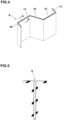
- FIG. 4 shows a see-through perspective view showing an example of the interior portion of the closed sipe 8
- FIG. 5 shows a cross-sectional view taken along line A-A of FIG. 4 .
- the edges of the closed sipe 8 at the tread surface is indicated by a solid line
- the shape of the interior portion of the closed sipe 8 is indicated by a broken line.
- the entire closed sipe 8 extends linearly in the tire radial direction in its sipe cross-section.
- the rigidity of the land portion 4 is maintained by the closed sipe 8 whose both ends are terminated within the land portion 4, therefore, sufficient steering stability and resistance to uneven wear are exhibited.
- the closed sipe 8 having such sipe cross section helps to improve demoldability during vulcanization molding, reduce the defect rate during tire production, and reduce manufacturing and maintenance costs for the vulcanization mold.
- FIG. 6 shows a see-through perspective view showing another example of the interior portion of the closed sipe 8.
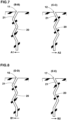
- FIG. 7 shows a B-B line cross-sectional view and a C-C line cross-sectional view of FIG. 6 .
- the first sipe piece 11 and the second sipe piece 12 are each configured as a bent portion 20 extending zigzag in the tire radial direction in the sipe cross section.
- Such closed sipe 8 increases the rigidity of the land portion 4 in the tire circumferential direction, and can exhibit excellent braking/driving performance on ice.
- the bent portion 20 includes an outer inclined portion 21 which continues to the edge of the closed sipe 8 and extends while inclining to one direction with respect to the tire radial direction.
- the outer inclined portion 21 belonging to the first sipe piece 11 is inclined to the first side A1 in the tire circumferential direction toward the inside in the tire radial direction.
- the outer inclined portion 21 belonging to the second sipe piece 12 is inclined to the second side A2 in the tire circumferential direction toward the inside in the tire radial direction.
- FIG. 8 shows a D-D line cross-sectional view and a E-E line cross-sectional view of FIG. 6 .
- each of the first outer sipe piece 16 and the second outer sipe piece 17 is configured as a bent portion 20 extending zigzag in the tire radial direction in the sipe cross-section.
- Such closed sipe 8 increases the rigidity of the land portion 4 in the tire axial direction, and can exhibit excellent turning performance on ice.
- the outer inclined portion 21 belonging to the first outer sipe piece 16 is inclined to the first side B1 in the tire axial direction toward the inside in the tire radial direction.
- the outer inclined portion 21 belonging to the second outer sipe piece 17 is inclined to the second side B2 in the tire axial direction toward the inside in the tire radial direction.
- the configuration of the bent portion 20 can be varied depending on the purpose of the tire.
- Such closed sipe 8 can exhibit excellent braking/driving performance on ice while improving demoldability during vulcanization molding.
- first outer sipe piece 16 and the second outer sipe piece 17 have the cross-sectional shapes shown in FIG. 8 , and other portions extend parallel to the tire radial direction, for example.
- Such closed sipe 8 can exhibit excellent turning performance on ice while improving demoldability during vulcanization molding.
- Fig. 9 shows a see-through perspective view showing the interior portion of yet another closed sipe 8.
- each sipe piece of the closed sipe 8 is configured as a bent portion 20 extending in a zigzag shape in the tire radial direction.
- Such closed sipe 8 when closed can further increase the rigidity of the land portion 4, and can exhibit excellent uneven wear resistance performance.
- the outer inclined portions 21 have the following configuration. That is, in the present embodiment, the outer inclined portion 21 belonging to the first sipe piece 11 and the outer inclined portion 21 belonging to the second sipe piece 12 are each inclined to the first side A1 in the tire circumferential direction toward the inside in the tire radial direction. In addition, the outer inclined portion 21 belonging to the first outer sipe piece 16 and the outer inclined portion 21 belonging to the second outer sipe piece 17 are each inclined to the first side B1 in the tire axial direction toward the inside in the tire radial direction.
- each sipe piece 13 is configured as the bent portion 20, and the above effects can be exhibited.
- the closed sipe 8 having the planar shape shown in FIGS. 2 and 3 may have any of the cross-sectional shapes shown in FIGS. 4 to 10 .
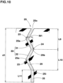
- the bent portion 20 includes two or more first convex portions 23 which are convex toward one side as shown in FIG. 10 .
- the bent portion 20 of the present embodiment is constructed by two first convex portions 23, and one second convex portion 24 which is convex toward the other side between the two first convex portions 23.
- the center line 25 in the width direction of the bent portion 20 comprises a first vertex 25a bent at the first convex portion 23 and a second vertex 25b bent at the second convex portion 24. Moreover, it is preferable that a virtual straight line (not shown) connecting between both ends of the center line 25 of the bent portion 20 is parallel to the tire radial direction. Moreover, it is preferable that the second vertex 25b is positioned on the virtual straight line.
- the center line 25 of the bent portion 20 includes an outer end 25o on the outer side in the tire radial direction, and an inner end 25i on the inner side in the tire radial direction.
- the bent portion 20 comprises two bent elements 30.
- the bent element 30 of the present embodiment is composed of a first bent element 31 from the outer end 25o to the second vertex 25b, and a second bent element 32 from the second vertex 25b to the inner end 25i.
- Such bent portion 20 can uniformly improve traction performance and braking performance on ice.
- the bending width w1 of the bent portion 20 (the distance in the width direction of the sipe from the first vertex 25a to the second vertex 25b) is, for example, 0.1 to 1.0 mm.
- the closed sipe 8 comprises a vertical portion 35 which continues to the inner side in the tire radial direction of the bent portion 20 and extends parallel to the tire radial direction.
- the length L11 in the tire radial direction of the vertical portion 35 is, for example, 10% to 30% of the maximum depth d1 of the closed sipe 8.
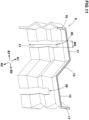
- FIG. 11 shows a see-through perspective view showing another example of the interior portion of the closed sipe 8.
- the closed sipe 8 of the present embodiment includes a connecting portion 26 in which sipe walls facing each other are partially connected with each other and which protrudes outward in the tire radial direction.
- the closed sipe 8 shown in Fig. 11 can suppress the above-described deformation by the connecting portion 26, it is possible to improve steering stability and braking performance even on ice.
- suppressing the deformation described above is highly effective in suppressing uneven wear (heel-and-toe wear). Therefore, the closed sipe 8 having the connecting portion 26 suppresses uneven wear, thereby reducing changes in tire performance due to wear, and thus it becomes possible to provide a tire capable of maintaining high safety over a long period of time.
- the connecting portion 26 is provided on at least one of the first sipe piece 11 and the second sipe piece 12, for example. In the present embodiment, as a more preferable mode, the connecting portion 26 is provided on each of the first sipe piece 11 and the second sipe piece 12.
- the height in the tire radial direction of the connecting portion 26 provided in the first sipe piece 11 is, for example, 80% to 120% of the height in the tire radial direction of the connecting portion 26 provided in the second sipe piece 12. Preferably, they are the same. Thereby, the rigidity around the closed sipe 8 is uniformly increased by the two connecting portions 26, and the above-described effects can be further improved.
- the connecting portion 26 extends in the tire radial direction with a constant width, for example.
- the width w2 of the connecting portion 26 provided in the first sipe piece 11 (the width along the length of the closed sipe 8) is preferably 10% to 50%, more preferably 20% to 30% of the length L4 (shown in FIG. 3 ) of the first sipe piece 11.
- the width of the connecting portion 26 provided on the second sipe piece 12 is set in the same range in relation to the length L5 (shown in FIG. 3 ) of the second sipe piece 12.
- the height h1 in the tire radial direction of the connecting portion 26 is, for example, 10% to 90% of the maximum depth d1 (shown in Fig. 10 ) of the closed sipe 8.
- the height h1 is appropriately determined according to the purpose of the tire. This is because, as shown in FIG. 12 , when the land portion 4 provided with the closed sipe 8 having the connecting portion 26 is worn, the connecting portion 26 is exposed and the edge component of the closed sipe 8 is reduced.
- the height h1 is 20% to 40% of the maximum depth d1 of the closed sipe 8.
- the height h1 is 50% to 70% of the depth d1.
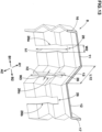
- Fig. 13 there is shown a see-through perspective view showing still another example of the interior portion of the closed sipe 8.
- the closed sipe 8 is provided with connecting portions 26 in the first sipe piece 11 and the second sipe piece 12 as in the embodiment shown in FIG. 11
- the third sipe piece 13 is also provided with a connecting portion 26.
- deformation of the closed sipe 8 in the tire axial direction is further suppressed. Therefore, further improvements in steering stability and turning performance on ice can be expected.
- the connecting portion 26 provided in the first sipe piece 11 may be referred to as a first connecting portion 26a, the connecting portion 26 provided in the second sipe piece 12 as a second connecting portion 26b, and the connecting portion 26 provided in the third sipe piece 13 as a third connecting portion 26c.
- first connecting portion 26a and the second connecting portion 26b shown in Fig. 13 the configurations of the connecting portions 26 shown in Fig. 11 can be applied, and the descriptions thereof will be omitted here. Further, in a preferred mode, the first connecting portion 26a and the second connecting portion 26b have substantially the same configuration. Thereby, progress of wear becomes uniform around the first sipe piece 11 and around the second sipe piece 12, and uneven wear is suppressed.
- the height h2 of the third connecting portion 26c is, for example, 10% to 90% of the maximum depth d1 (shown in Fig. 10 ) of the closed sipe 8.
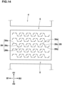
- the height h2 is appropriately determined according to the purpose of the tire. This is because, as shown in FIG. 14 , when the land portion 4 provided with the closed sipe 8 having the connecting portion 26 is worn, the first connecting portion 26a, the second connecting portion 26b, and the third connecting portion 26c are exposed, and the edge component of the closed sipe 8 is reduced.
- the height h2 is 20% to 40% of the maximum depth d1 of the closed sipe 8.
- the height h2 is 50% to 70% of the depth d1.
- the height h2 of the third connecting portion 26c is, for example, 40% to 100% of the height h1 of the first connecting portion 26a or the second connecting portion 26b.
- the height h1 is the same as the height h2. Thereby, uneven wear is further suppressed.
- the width w3 of the third connecting portion 26c (the width along the length direction of the closed sipe 8) is, for example, 10% to 50%, preferably 20% to 30% of the length L12 of the third sipe piece 13 (the length along the length direction of the closed sipe 8).
- the widths w2 of the first connecting portion 26a and the second connecting portion 26b and the width w3 of the third connecting portion 26c are the same. Thereby, it is possible to further suppress uneven wear around the closed sipe 8.
- FIGS. 15 and 16 there are shown enlarged plan views of land portions of other embodiments of the present disclosure.
- the same reference numerals are assigned to the configurations described above, and descriptions thereof are omitted here.
- a sipe which is adjacent to a longitudinal edge 6e extending in the tire circumferential direction of the block 6, is configured as a non-closed sipe 9 communicating with the longitudinal edge 6e.
- the non-closed sipe 9 of the present embodiment has, for example, such a shape that the closed sipe 8 communicates with the longitudinal edge 6e at the first sipe piece 11 or the second sipe piece 12.
- Such sipe configuration helps to further improve the braking/driving performance on ice.
- the block 6 of the embodiment shown in Fig. 16 is provided with a sipe group 7 of closed sipes 8 arranged obliquely with respect to the tire axial direction.
- a virtual straight line 18 (indicated by a two-dot chain line), which connects between a first end 8a of the closed sipe 8 provided at the end on the first side B1 in the tire axial direction and a second end 8b of the closed sipe 8 provided at the end on the second side B2 in the tire axial direction, is, for example, 10 to 45 degrees with respect to the tire axial direction.
- turning performance on ice is improved.
- the closed sipes 8 of the present disclosure are provided in at least shoulder blocks.
- the shoulder block is a block included in a shoulder land portion located on the outermost side in the tire axial direction of the tread portion 2 .
- the closed sipes 8 of the present disclosure can be expected to increase block stiffness compared to conventional sipes. Therefore, by providing the closed sipes 8 of the present disclosure in the shoulder blocks, the braking performance on dry road surfaces can be effectively improved.
- the closed sipe 8 including the connecting portions 26 shown in FIG. 11 or 13 can reliably increase the rigidity of the block and further improve the braking performance on dry road surfaces.
- Pneumatic tires of size 195/65R15 having the above-described sipe group were experimentally manufactured based on the specifications in Table 1.
- a tire in which a block a was provided with a plurality of sipes b extending in a zigzag pattern as shown in FIG. 17 was experimentally manufactured.
- the sipe b of the comparative example extends linearly in the tire radial direction as a whole.
- Each test tire had substantially the same configuration, except for the shape of the sipe.
- Each test tire was tested for traction performance on ice, braking performance on ice, and turning performance on ice. Common specifications to the test tires and test methods are as follows.
- the braking performance was evaluated by the driver's senses.
- the results are grades based on the braking performance of the comparative example being 100, and a higher value indicates better braking performance on ice.
- the turning performance was evaluated by the driver's senses.
- the results are grades based on the turning performance of the comparative example being 100, and a higher value indicates better turning performance on ice.
- each example tire had improved braking/driving performance and turning performance on ice as compared to the comparative example.
- the present disclosure includes the following modes.
- a tire including a tread portion, wherein the tread portion includes a land portion,
- each of the first sipe piece and the second sipe piece extends at an angle of +/-10 degrees with respect to the tire axial direction.
- the closed sipe includes a bent portion extending in the tire radial direction in a zigzag manner in a sipe cross section.
- the bent portion includes at least two bent elements which are convex toward the same direction.
- the closed sipe includes a vertical portion which continues to an inside in the tire radial direction of the bent portion and extends parallel to the tire radial direction.
- the closed sipe includes a connecting portion in which sipe walls facing each other are connected to each other and which protrudes outward in the tire radial direction.
- the connecting portion is provided in each of the first sipe piece and the second sipe piece, and the height in the tire radial direction of the connecting portion provided in the first sipe piece is the same as the height in the tire radial direction of the connecting portion provided in the second sipe piece.
- tread portion includes a shoulder land portion positioned on the outermost side in the tire axial direction
Landscapes
- Engineering & Computer Science (AREA)
- Mechanical Engineering (AREA)
- Tires In General (AREA)
Abstract
Description
- The present disclosure relates to a tire.
- Conventionally, there have been proposed various pneumatic tires in which linear or zigzag sipes are provided in land portions of a tread portion (see, for example,
Patent Document 1 below). The sipes exert a road surface scratching force (edge effect) by their edges, and consequently enhance performance on ice. - Patent Document 1:
Japanese Patent Application Publication No. 2003-025812 - In general, high traction performance and braking performance on ice (Hereinafter, these may be collectively referred to as "braking/driving performance") are required. Therefore, in many cases, the land portions of the tread portion are provided with a plurality of sipes extending in the tire axial direction and arranged in the tire circumferential direction.
- In recent years, on the other hand, as the performance of vehicles become improved, there is a demand for improved turning performance on ice.
Therefore, in some cases, in order to increase the frictional force in the tire axial direction, sipes including a component extending in the tire circumferential direction are arranged. When a plurality of such sipes are arranged in the tire circumferential direction, the number of the sipes which can be arranged per unit length in the tire circumferential direction of the land portion tends to decrease. Therefore, there is a possibility that the braking/driving performance on ice will be impaired. - In view of the above problems, the present disclosure has been devised, and
a main problem is to provide a tire improved in braking/driving performance and turning performance on ice. - The present disclosure is a tire including a tread portion, wherein
- the tread portion includes a land portion,
- in the land portion, a plurality of closed sipes having a width of not more than 1.5 mm are arranged in the tire axial direction,
- each of the closed sipes includes a first end, a second end, a first sipe piece extending in the tire axial direction on the first end side, a second sipe piece extending in the tire axial direction on the second end side, and a third sipe piece inclined with respect to the tire axial direction between the first sipe piece and the second sipe piece, and
- the closed sipes are arranged in the tire axial direction overlapping with each other in the tire axial direction and the tire circumferential direction.
- In the present disclosure, by adopting the above configurations, it is possible to exhibit excellent braking/driving performance and turning performance on ice.
-
- [
FIG. 1 ]
A cross-sectional view of a tread portion of a tire according to an embodiment of the present disclosure. - [
FIG. 2 ]
An enlarged plan view of a land portion inFIG. 1 . - [
FIG. 3 ]
An enlarged view of a closed sipe inFIG. 2 . - [
FIG. 4 ]
A see-through perspective view showing an example of the interior portion of the closed sipe. - [
FIG. 5 ]
A cross-sectional view taken along line A-A ofFIG. 4 . - [
FIG. 6 ]
A see-through perspective view showing another example of the interior portion of the closed sipe. - [
FIG. 7 ]
A sectional view taken along line B-B and a sectional view taken along line C-C ofFIG. 6 . - [
FIG. 8 ]
A sectional view taken along line D-D and a sectional view taken along line E-E ofFIG. 6 . - [
FIG. 9 ]
A see-through perspective view showing another example of the interior portion of the closed sipe. - [
FIG. 10 ]
An enlarged sectional view of a bent portion. - [
FIG. 11 ]
A see-through perspective view showing another example of the interior portion of the closed sipe. - [
FIG. 12 ]
An enlarged plan view of the land portion provided with the closed sipes shown inFIG.11 when the land portion is worn. - [
FIG. 13 ]
A see-through perspective view showing still another example of the interior portion of the closed sipe. - [
FIG. 14 ]
An enlarged plan view of the land portion provided with the closed sipes shown inFIG.13 when the land portion is worn. - [
FIG. 15 ]
An enlarged plan view of a land portion of another embodiment of the present disclosure. - [
FIG. 16 ]
An enlarged plan view of a land portion of another embodiment of the present disclosure. - [
FIG. 17 ]
An enlarged plan view of a land portion of a tire as a comparative example. -
- 2
- Tread portion
- 4
- Land portion
- 8
- closed sipe
- 8a
- First end
- 8b
- Second end
- 11
- First sipe piece
- 12
- Second sipe piece
- 13
- Third sipe piece
- Hereinafter, an embodiment of the present disclosure will be described based on the drawings.
FIG. 1 shows a cross-sectional view of atread portion 2 of atire 1 of the present embodiment.FIG. 1 is a meridian cross sectional view including the tire rotation axis, of thetire 1 under a normal state.
Thetire 1 of the present embodiment is suitably used as, for example, a pneumatic tire for passenger cars. However, it is not limited to such an embodiment, and thetire 1 of the present disclosure may be used for heavy loads, for example. - In the case of a pneumatic tire for which various standards have been established, the "normal state" is a state in which the tire mounted on a regular rim is inflated to a regular internal pressure but loaded with no load.
In the case of tires for which various standards have not been established or non-pneumatic tires, the normal state means a standard usage state corresponding to the purpose of use of the tire and a no-load state.
In this specification, unless otherwise specified, dimensions and the like of various parts of the tire are the values measured under the normal state.
εach of the configurations described in this specification shall allow for normal errors involved in rubber molded products. - The "regular rim" is a rim defined for each tire by a standard in a standard system including the standard on which the tire is based, for example, "standard Rim" in JATMA, "Design Rim" in TRA, and "Measuring Rim" in ETRTO,
- The "regular internal pressure" is air pressure defined for each tire by a standard in a standard system including the standard on which the tire is based, for example, "MAXIMUM AIR PRESSURE" in JATMA, the maximum value listed in the table "TIRE LOAD LIMITS AT VARIOUS COLD INFLATION PRESSURES" in TRA, "INFLATION PRESSURE" in ETRTO.
- As shown in
FIG. 1 , thetread portion 2 is provided with, for example, a plurality ofmain grooves 3 continuously extending in the tire circumferential direction, and a plurality ofland portions 4 divided thereby. -
FIG. 2 shows an enlarged plan view of theland portion 4. As shown inFIG. 2 , theland portion 4 of the present embodiment is configured, for example, as a row of blocks including a plurality ofblocks 6 in the tire circumferential direction. Theblocks 6 are defined between a plurality oflateral grooves 5 crossing theland portion 4 in the tire axial direction. - The
land portion 4 of the present disclosure is not limited to such an example, and may be a rib continuously extending in the tire circumferential direction, for example. - In some of the figures in this specification, there are indicated by arrows,
- a first side A1 in the tire circumferential direction,
- a second side A2 in the tire circumferential direction opposite thereto,
- a first side B1 in the tire axial direction, and
- a second side B2 in the tire axial direction opposite thereto. Unless otherwise noted, in the figures showing the plan views of the
land portions 4, - the upward direction is the first side A1 in the tire circumferential direction,
- the downward direction is the second side A2 in the tire circumferential direction,
- the left direction is the first side B1 in the tire axial direction, and
- the right direction is the second side B2 in the tire axial direction.
- In the
land portion 4, a plurality ofclosed sipes 8 are arranged in the tire axial direction.
In the present embodiment, a plurality ofsipe groups 7 each made up of a plurality ofclosed sipes 8 is disposed in oneblock 6. For example, onesipe group 7 is made up of 3 to 7closed sipes 8. - In this specification, the "sipe" is a slit having a minute width, and refers to that having a width of 1.5 mm or less between two sipe walls facing each other.
As a preferable mode, the above-said width of theclosed sipe 8 of the present embodiment is 1.0 mm or less.
In addition, in this specification, the term "closed sipe" refers to a sipe whose both ends are terminated within theland portion 4. Thesipe group 7 provided in theblock 6 of the present embodiment consists of theclosed sipes 8 only. In other words, none of the sipes are connected to the edges of theblock 6.
The present invention is however, not limited to such a mode, and the sipe arranged near the edge of theblock 6 may be a non-closed sipe having one end opened at the edge. - In
FIG. 3 , there is shown an enlarged view of theclosed sipe 8 ofFIG. 2 .
As shown inFIG. 3 , eachclosed sipe 8 comprises afirst end 8a and asecond end 8b, and afirst sipe piece 11, asecond sipe piece 12 and athird sipe piece 13.
Thefirst end 8a is the end of theclosed sipe 8 on the first side B1 in the tire axial direction.
Thesecond end 8b is the end of theclosed sipe 8 on the second side B2 in the tire axial direction.
Thefirst sipe piece 11 extends in the tire axial direction on thefirst end 8a side of thethird sipe piece 13.
Thesecond sipe piece 12 extends in the tire axial direction on thesecond end 8b side of thethird sipe piece 13.
Between thefirst sipe piece 11 and thesecond sipe piece 12, thethird sipe piece 13 is inclined with respect to the tire axial direction.
With this arrangement, in theclosed sipe 8 of the present embodiment, thefirst sipe piece 11 is positioned on the first side A1 in the tire circumferential direction and on the first side B1 in the tire axial direction of thesecond sipe piece 12. Further, in the present embodiment, thefirst sipe piece 11 continues to thethird sipe piece 13 om the first side A1 in the tire circumferential direction.
Thesecond sipe piece 12 continues to thethird sipe piece 13 on the second side A2 in the tire circumferential direction. - The
closed sipes 8 arranged in the tire axial direction overlap each other in the tire axial direction and the tire circumferential direction.
The expression "theclosed sipes 8 overlap each other in the tire axial direction" means such a mode that a virtual region obtained by extending oneclosed sipe 8 parallel to the tire circumferential direction overlaps with theclosed sipe 8 adjacent thereto.
The expression "theclosed sipes 8 overlap each other in the tire circumferential direction" means such a mode that a virtual region obtained by extending oneclosed sipe 8 in parallel with the tire axial direction overlaps theclosed sipe 8 adjacent thereto. - In the present disclosure, by adopting the above configurations, it is possible to exhibit excellent braking/driving performance and turning performance on ice.
The reason for this is presumed to be the following mechanism. - The
sipe group 7 of the present disclosure includes a plurality ofclosed sipes 8 arranged in the tire axial direction. Since theclosed sipes 8 are difficult to open during braking and driving, they are less likely to be clogged with snow or ice inside, and the edge effect can be stably exhibited over a long period of time. Thus, the anti-snow clogging performance when running on snow is improved.
In addition, theclosed sipes 8 increase the pattern rigidity of theland portion 4 and enhance the steering stability on dry road surfaces. - Further, since the
third sipe piece 13 is inclined with respect to the tire axial direction, it exerts a frictional force in the tire axial direction on ice, thereby capable of improving turning performance on ice.
Furthermore, since thesecond sipe piece 12 of theclosed sipe 8 overlaps thefirst sipe piece 11 of theclosed sipe 8 adjacent in the tire axial direction and the tire circumferential direction, it is possible to provide manyclosed sipes 8 in theland portion 4, and excellent braking/driving performance can be exhibited on ice. - In the present embodiment, a virtual region obtained by extending the
second sipe piece 12 of oneclosed sipe 8 parallel to the tire circumferential direction overlaps with thefirst sipe piece 11 of theclosed sipe 8 adjacent thereto.
Further, a virtual region obtained by extending thethird sipe piece 13 of oneclosed sipe 8 parallel to the tire axial direction overlaps with thethird sipe piece 13 of theclosed sipe 8 adjacent thereto. The present disclosure is however, not limited to such a mode. - Hereinafter, a more detailed configuration of the present embodiment will be described.
As shown inFIG. 2 , thesipe group 7 of the present embodiment extends along the tire axial direction, but may extend with a certain degree of inclination with respect to the tire axial direction.
Specifically, an virtual straight line 18 (indicated by a two-dot chain line), which connecting between afirst end 8a of theclosed sipe 8 provided at the end on the first side B1 in the tire axial direction, and afirst end 8b of theclosed sipe 8 provided at the end on the second side B2 in the tire axial direction, is, for example, 45 degrees or less, preferably 15 degrees or less, and more preferably 5 degrees or less with respect to the tire axial direction.
Thesipe group 7 is however, not limited to such a mode, and can be changed according to the shape of the land portion, and as described later, for example, the virtualstraight line 18 may extend obliquely. - As a further preferable mode, in the present embodiment, the
first end 8a of eachclosed sipe 8 is placed in the same imaginary zone 15 (colored inFIG. 2 ) extending parallel to the tire axial direction with a minute width.
The width of theimaginary zone 15 is, for example, 3.0 mm or less. As a further preferable mode, the first ends 8a of the respectiveclosed sipes 8 are placed on a same virtual straight line extending parallel to the tire axial direction.
Similarly, thesecond end 8b of eachclosed sipe 8 is placed in the same imaginary zone (not shown) extending parallel to the tire axial direction with a minute width.
The width of the imaginary zone is, for example, 3.0 mm or less.
As a further preferable mode, the second ends 8b of the respectiveclosed sipes 8 are placed on a same virtual straight line extending parallel to the tire axial direction. - It is preferable that, as shown in
FIG. 3 , the overlapping length L2 of twoclosed sipes 8 adjacent to each other in the tire axial direction is 10% to 40% of the maximum length L1 in the tire axial direction of theclosed sipe 8.
Thereby, excellent braking/driving performance is exhibited while maintaining the wear resistance of theland portion 4.
If the overlapping length L2 is less than 10% of the length L1, the edge component in the tire axial direction disposed on theland portion 4 is reduced, and the braking/driving performance on ice may deteriorate.
If the overlapping length L2 exceeds 40% of the length L1, the clearance between twoclosed sipes 8 adjacent to each other becomes narrow, which may cause uneven wear of the land portion. εach length of the sipe is measured at the widthwise center line of the sipe. - The distance L3 in the tire circumferential direction between the
second end 8b of oneclosed sipe 8 and thefirst end 8a of theclosed sipe 8 adjacent thereto is, for example, not more than 10%, preferably not more than 5% of the length L6 in the tire circumferential direction thethird sipe piece 13.
In the present embodiment, thesecond end 8b is positioned on the first side A1 in the tire circumferential direction than thefirst end 8a.
Thereby, a decrease in rigidity of theland portion 4 is suppressed, and wear resistance performance and steering stability on dry road surfaces are ensured. - In the present embodiment, the
first end 8a and thesecond end 8b are located
on the second side A2 in the tire circumferential direction of thefirst sipe piece 11, and on the first side A1 in the tire circumferential direction of thesecond sipe piece 12.
In other words, thefirst end 8a and thesecond end 8b are located within a region (not shown) formed by extending thethird sipe piece 13 toward both sides in the tire axial direction in parallel with the tire axial direction.
Moreover, theclosed sipe 8 of the present embodiment includes a firstouter sipe piece 16 and a secondouter sipe piece 17.
The firstouter sipe piece 16 extends from thefirst end 8a to thefirst sipe piece 11.
The secondouter sipe piece 17 extends from thesecond end 8b to thesecond sipe piece 12.
Suchclosed sipe 8 provides a large frictional force in the tire axial direction by means of the firstouter sipe piece 16 and the secondouter sipe piece 17, thereby enhancing turning performance on ice. - The angle between the
first sipe piece 11 and thethird sipe piece 13 and - the angle between the
second sipe piece 12 and thethird sipe piece 13 - are each, for example, not less than 80 degrees, preferably not less than 90 degrees.
- From a similar point of view, the angle between the
first sipe piece 11 and the firstouter sipe piece 16 and the angle between thesecond sipe piece 12 and the second outer sipe piece are each, for example, not less than 80 degrees, preferably not less than 90 degrees. In the present embodiment, the above two angles are 100 to 120 degrees. - In this embodiment, each of the sipe pieces of the
closed sipe 8 extends linearly.
For example, each of the sipe pieces may extend in a curved manner. - εach of the axial length L4 of the
first sipe piece 11 and the axial length L5 of thesecond sipe piece 12 is greater than the axial length of thethird sipe piece 13.
Each of the length L4 of thefirst sipe piece 11 and the length L5 of thesecond sipe piece 12 is 35% to 45% of the axial length L1 of theclosed sipe 8. - The angle of the
first sipe piece 11 with respect to the tire axial direction and the angle of thesecond sipe piece 12 with respect to the tire axial direction are, for example, in a range of +/-20 degrees, preferably in a range of +/-10 degrees. εach of thefirst sipe piece 11 and thesecond sipe piece 12 of the present embodiment extends parallel to the tire axial direction. Suchfirst sipe piece 11 andsecond sipe piece 12 help to effectively enhance the braking/driving performance on ice. - As shown in
FIG. 2 , in a more preferable mode, thefirst sipe pieces 11 of theclosed sipes 8 are arranged in a same imaginary zone (not shown) extending parallel to the tire axial direction with a minute width. The width of the imaginary zone is, for example, 3.0 mm or less.
In a more preferable mode, thefirst sipe pieces 11 of theclosed sipes 8 are arranged on a same virtual straight line extending parallel to the tire axial direction.
Thereby, the braking/driving performance is improved while maintaining the uneven wear resistance performance. - Similarly, the
second sipe pieces 12 of theclosed sipes 8 are arranged in a same imaginary zone (not shown) extending parallel to the tire axial direction with a minute width. The width of the imaginary zone is, for example, 3.0 mm or less.
In a more preferable mode, thesecond sipe pieces 12 of theclosed sipes 8 are arranged on a same virtual straight line extending parallel to the tire axial direction. - As shown in
FIG. 3 , the length L6 in the tire circumferential direction of thethird sipe piece 13 is, for example, smaller than the length L1 in the tire axial direction of theclosed sipe 8.
The length L6 of thethird sipe piece 13 is smaller than the length L4 in the tire axial direction of thefirst sipe piece 11 and the length L5 in the tire axial direction of thesecond sipe piece 12.
Specifically, the length L6 of thethird sipe piece 13 is 25% to 40% of the length L1 of theclosed sipe 8.
Suchthird sipe piece 13 enhances turning performance on ice while maintaining uneven wear resistance performance. - The
third sipe piece 13, for example, is inclined to the second side A2 in the tire circumferential direction from thefirst sipe piece 11 toward the second side B2 in the tire axial direction.
Thethird sipe piece 13 is arranged at a larger angle with respect to the tire axial direction than thefirst sipe piece 11 and thesecond sipe piece 12.
However, thethird sipe piece 13 may, for example, extend parallel to the tire circumferential direction.
The angle of thethird sipe piece 13 of the present embodiment with respect to the tire axial direction is, for example, not less than 45 degrees, preferably 60 to 80 degrees. Suchthird sipe piece 13 improves turning performance on ice, while providing frictional force in the tire circumferential direction too. - As shown in
FIG. 2 , theclosed sipes 8 of the present embodiment are arranged so that thethird sipe pieces 13 become parallel to each other.
Thereby, the uneven wear resistance of theland portion 4 and the steering stability on dry road surfaces are improved. - As shown in
FIG. 3 , the length L7 in the tire circumferential direction of the firstouter sipe piece 16 and the length L8 in the tire circumferential direction of the secondouter sipe piece 17 are, for example, smaller than the length in the tire circumferential direction of thethird sipe piece 13.
The length L7 of the firstouter sipe piece 16 and the length L8 of the secondouter sipe piece 17 are preferably not more than 60%, more preferably 45% to 55% of the length L6 of thethird sipe piece 13. This ensures a sufficient clearance between twoclosed sipes 8 adjacent to each other. Therefore, uneven wear resistance is maintained, and demoldability during vulcanization molding is ensured. - with respect to the tire circumferential direction, the first
outer sipe piece 16 and the secondouter sipe piece 17 are each inclined in a direction opposite to thethird sipe piece 13. The angle of the firstouter sipe piece 16 with respect to the tire circumferential direction and the angle of the secondouter sipe piece 17 with respect to the tire circumferential direction are each, for example, not more than 45 degrees, preferably 10 to 30 degrees.
In a preferable mode, the angle of the firstouter sipe piece 16 and the angle of the secondouter sipe piece 17 are the same as the angle of thethird sipe piece 13 with respect to the tire circumferential direction.
However, it is not limited to such mode, and the firstouter sipe piece 16 and the secondouter sipe piece 17 may extend parallel to the tire circumferential direction, for example. - In the present embodiment, in two
closed sipes 8 adjacent in the tire axial direction, thesecond sipe piece 12 of theclosed sipe 8 on one side overlaps in the tire axial direction with thefirst sipe piece 11 of theclosed sipe 8 on the other side.
The secondouter sipe piece 17 of theclosed sipe 8 on one side extends from thesecond sipe piece 12 toward the first side A1 in the tire circumferential direction.
The firstouter sipe piece 16 of theclosed sipe 8 on the other side extends from thefirst sipe piece 11 toward the second side A2 in the tire circumferential direction.
Thereby, the above-described effects are exhibited more reliably. - Next, the internal configuration of the
closed sipe 8 will be described.
FIG. 4 shows a see-through perspective view showing an example of the interior portion of theclosed sipe 8, and
FIG. 5 shows a cross-sectional view taken along line A-A ofFIG. 4 . In this specification, in a see-through perspective view such asFIG. 4 , the edges of theclosed sipe 8 at the tread surface is indicated by a solid line, and the shape of the interior portion of theclosed sipe 8 is indicated by a broken line. - As shown in
FIGS. 4 and 5 , in the present embodiment, the entireclosed sipe 8 extends linearly in the tire radial direction in its sipe cross-section.
In the present disclosure, even if the cross-sectional shape of the sipe is linear as described above, the rigidity of theland portion 4 is maintained by theclosed sipe 8 whose both ends are terminated within theland portion 4, therefore, sufficient steering stability and resistance to uneven wear are exhibited. On the other hand, theclosed sipe 8 having such sipe cross section helps to improve demoldability during vulcanization molding, reduce the defect rate during tire production, and reduce manufacturing and maintenance costs for the vulcanization mold. -
FIG. 6 shows a see-through perspective view showing another example of the interior portion of theclosed sipe 8.FIG. 7 shows a B-B line cross-sectional view and a C-C line cross-sectional view ofFIG. 6 .
In the present embodiment, as shown inFIGS. 6 and7 , thefirst sipe piece 11 and thesecond sipe piece 12 are each configured as abent portion 20 extending zigzag in the tire radial direction in the sipe cross section.
Suchclosed sipe 8 increases the rigidity of theland portion 4 in the tire circumferential direction, and can exhibit excellent braking/driving performance on ice. - The
bent portion 20 includes an outerinclined portion 21 which continues to the edge of theclosed sipe 8 and extends while inclining to one direction with respect to the tire radial direction.
In the embodiment shown inFIG. 6 , the outerinclined portion 21 belonging to thefirst sipe piece 11 is inclined to the first side A1 in the tire circumferential direction toward the inside in the tire radial direction. Whereas the outerinclined portion 21 belonging to thesecond sipe piece 12 is inclined to the second side A2 in the tire circumferential direction toward the inside in the tire radial direction.
Thereby, a rubber portion surrounded by thefirst sipe piece 11, thethird sipe piece 13 and the firstouter sipe piece 16, and a rubber portion surrounded by thesecond sipe piece 12, thethird sipe piece 13 and the secondouter sipe piece 17, secure large volumes, and as a result, it is possible to suppress rubber chipping at the time of demolding during vulcanization molding. -
FIG. 8 shows a D-D line cross-sectional view and a E-E line cross-sectional view ofFIG. 6 .
As shown inFIGS. 6 and8 , in the present embodiment, each of the firstouter sipe piece 16 and the secondouter sipe piece 17 is configured as abent portion 20 extending zigzag in the tire radial direction in the sipe cross-section.
Suchclosed sipe 8 increases the rigidity of theland portion 4 in the tire axial direction, and can exhibit excellent turning performance on ice. - In the embodiment shown in
Fig. 6 , the outerinclined portion 21 belonging to the firstouter sipe piece 16 is inclined to the first side B1 in the tire axial direction toward the inside in the tire radial direction.
The outerinclined portion 21 belonging to the secondouter sipe piece 17 is inclined to the second side B2 in the tire axial direction toward the inside in the tire radial direction.
Thereby, it is possible to suppress rubber chipping at the time of demolding during vulcanization molding by the same mechanism as described above. - In the present disclosure, the configuration of the
bent portion 20 can be varied depending on the purpose of the tire.
In another embodiment, it may be possible that thefirst sipe piece 11 and thesecond sipe piece 12 have the cross-sectional shapes shown inFIG. 7 , and other portions extend parallel to the tire radial direction, for example.
Suchclosed sipe 8 can exhibit excellent braking/driving performance on ice while improving demoldability during vulcanization molding. - In yet another embodiment, it may be possible that the first
outer sipe piece 16 and the secondouter sipe piece 17 have the cross-sectional shapes shown inFIG. 8 , and other portions extend parallel to the tire radial direction, for example.
Suchclosed sipe 8 can exhibit excellent turning performance on ice while improving demoldability during vulcanization molding. -
Fig. 9 shows a see-through perspective view showing the interior portion of yet anotherclosed sipe 8.
As shown inFIG. 9 , in the present embodiment, each sipe piece of theclosed sipe 8 is configured as abent portion 20 extending in a zigzag shape in the tire radial direction.
Suchclosed sipe 8 when closed, can further increase the rigidity of theland portion 4, and can exhibit excellent uneven wear resistance performance. - In the embodiment shown in
FIG. 9 , the inclination directions of the outerinclined portions 21 of the respective sipe pieces interfere with each other.
Therefore, in the present embodiment, it is preferable that the outerinclined portions 21 have the following configuration.
That is, in the present embodiment, the outerinclined portion 21 belonging to thefirst sipe piece 11 and the outerinclined portion 21 belonging to thesecond sipe piece 12 are each inclined to the first side A1 in the tire circumferential direction toward the inside in the tire radial direction.
In addition, the outerinclined portion 21 belonging to the firstouter sipe piece 16 and the outerinclined portion 21 belonging to the secondouter sipe piece 17 are each inclined to the first side B1 in the tire axial direction toward the inside in the tire radial direction.
Further, the outerinclined portion 21 belonging to thethird sipe piece 13 is inclined to the second side B2 in the tire axial direction toward the inside in the tire radial direction.
With the above configuration, each sipe piece is configured as thebent portion 20, and the above effects can be exhibited. - In the present disclosure, the
closed sipe 8 having the planar shape shown inFIGS. 2 and3 may have any of the cross-sectional shapes shown inFIGS. 4 to 10 . - In
FIG. 10 , there is shown an enlarged cross-sectional view of thebent portion 20. It is preferable that thebent portion 20 includes two or more firstconvex portions 23 which are convex toward one side as shown inFIG. 10 .
Thebent portion 20 of the present embodiment is constructed by two firstconvex portions 23, and one secondconvex portion 24 which is convex toward the other side between the two firstconvex portions 23. - The
center line 25 in the width direction of thebent portion 20 comprises afirst vertex 25a bent at the firstconvex portion 23 and asecond vertex 25b bent at the secondconvex portion 24.
Moreover, it is preferable that a virtual straight line (not shown) connecting between both ends of thecenter line 25 of thebent portion 20 is parallel to the tire radial direction. Moreover, it is preferable that thesecond vertex 25b is positioned on the virtual straight line. - The
center line 25 of thebent portion 20 includes an outer end 25o on the outer side in the tire radial direction, and aninner end 25i on the inner side in the tire radial direction. Thebent portion 20 comprises twobent elements 30. Thebent element 30 of the present embodiment is composed of a firstbent element 31 from the outer end 25o to thesecond vertex 25b, and a secondbent element 32 from thesecond vertex 25b to theinner end 25i.
In the present embodiment, the length L9 in the tire radial direction of the first bent element 31 (the distance in the tire radial direction from the outer end 25o to thesecond vertex 25b) and the length L10 in the tire radial direction of the second bent element 32 (the distance in the tire radial direction from theinner end 25i to thesecond vertex 25b) are the same as each other. Suchbent portion 20 can uniformly improve traction performance and braking performance on ice. - The bending width w1 of the bent portion 20 (the distance in the width direction of the sipe from the
first vertex 25a to thesecond vertex 25b) is, for example, 0.1 to 1.0 mm.
Thereby, molding defects during vulcanization molding are suppressed while exhibiting the above-described effects. - It is preferable that the
closed sipe 8 comprises avertical portion 35 which continues to the inner side in the tire radial direction of thebent portion 20 and extends parallel to the tire radial direction.
The length L11 in the tire radial direction of thevertical portion 35 is, for example, 10% to 30% of the maximum depth d1 of theclosed sipe 8.
Thereby, during vulcanization molding, a knife blade of the vulcanization mold for forming thebent portion 20 can easily pierce the raw rubber of the tire, thereby, deformation and breakage of the knife blade are suppressed. -
FIG. 11 shows a see-through perspective view showing another example of the interior portion of theclosed sipe 8. As shown inFIG. 11 , theclosed sipe 8 of the present embodiment includes a connectingportion 26 in which sipe walls facing each other are partially connected with each other and which protrudes outward in the tire radial direction. - In general, when a sipe contact with the ground and a load in the tire circumferential direction is applied, shear deformation such that one sipe wall and the other sipe wall of the sipe are displaced in the depth direction of the sipe is likely to occur.
In addition, such deformation may lead to a decrease in the rigidity of the tread portion in the tire circumferential direction, which may lead to a decrease in braking performance on dry road surfaces and on ice, and uneven wear such as heel-and-toe wear around the sipes.
In addition, such uneven wear tends to make deterioration in tire performance due to wear more pronounced. - Since the
closed sipe 8 shown inFig. 11 can suppress the above-described deformation by the connectingportion 26, it is possible to improve steering stability and braking performance even on ice.
In addition, suppressing the deformation described above is highly effective in suppressing uneven wear (heel-and-toe wear). Therefore, theclosed sipe 8 having the connectingportion 26 suppresses uneven wear, thereby reducing changes in tire performance due to wear, and thus it becomes possible to provide a tire capable of maintaining high safety over a long period of time. - In addition, since the above-described
closed sipe 8 is difficult to open, the inside of the sipe is less likely to be clogged with snow during running. Such action suppresses the swelling of the side wall of theblock 6 provided with theclosed sipes 8, so the volume of the groove separating theblock 6 can be secured, thereby it becomes possible to suppress the deterioration of the performance on snow and ice. - The above-described deformation of the sipe tends to occur first in a portion of the sipe having a large component in the tire axial direction, and propagates to a portion of the sipe having a large component in the tire circumferential direction. Therefore, it is preferable to suppress the deformation in the portion of the sipe where the component in the tire axial direction is large.
From this point of view, it is preferable that the connectingportion 26 is provided on at least one of thefirst sipe piece 11 and thesecond sipe piece 12, for example.
In the present embodiment, as a more preferable mode, the connectingportion 26 is provided on each of thefirst sipe piece 11 and thesecond sipe piece 12. Thereby, the above-described effects can be surely obtained. - The height in the tire radial direction of the connecting
portion 26 provided in thefirst sipe piece 11 is, for example, 80% to 120% of the height in the tire radial direction of the connectingportion 26 provided in thesecond sipe piece 12. Preferably, they are the same. Thereby, the rigidity around theclosed sipe 8 is uniformly increased by the two connectingportions 26, and the above-described effects can be further improved. - The connecting
portion 26 extends in the tire radial direction with a constant width, for example.
The width w2 of the connectingportion 26 provided in the first sipe piece 11 (the width along the length of the closed sipe 8) is preferably 10% to 50%, more preferably 20% to 30% of the length L4 (shown inFIG. 3 ) of thefirst sipe piece 11.
The width of the connectingportion 26 provided on thesecond sipe piece 12 is set in the same range in relation to the length L5 (shown inFIG. 3 ) of thesecond sipe piece 12.
Thereby, the above effects can be sufficiently exhibited while maintaining the frictional force provided by the edges of theclosed sipe 8.
when the width of the connectingportion 26 changes in the tire radial direction, the width is measured at the center position in the tire radial direction of the connectingportion 26. - The height h1 in the tire radial direction of the connecting
portion 26 is, for example, 10% to 90% of the maximum depth d1 (shown inFig. 10 ) of theclosed sipe 8.
On the other hand, it is preferable that the height h1 is appropriately determined according to the purpose of the tire. This is because, as shown inFIG. 12 , when theland portion 4 provided with theclosed sipe 8 having the connectingportion 26 is worn, the connectingportion 26 is exposed and the edge component of theclosed sipe 8 is reduced. - From this point of view, as shown in
FIG. 11 , in the case of a winter tire emphasizing on-snow performance, it is preferable that the height h1 is 20% to 40% of the maximum depth d1 of theclosed sipe 8. On the other hand, in the case of an all-season tire for year-round use, it is preferable that the height h1 is 50% to 70% of the depth d1. Thereby, performance appropriate to the purpose of the tire can be obtained. - In
Fig. 13 , there is shown a see-through perspective view showing still another example of the interior portion of theclosed sipe 8.
In the present embodiment, theclosed sipe 8 is provided with connectingportions 26 in thefirst sipe piece 11 and thesecond sipe piece 12 as in the embodiment shown inFIG. 11 , and further, thethird sipe piece 13 is also provided with a connectingportion 26.
In the embodiment ofFIG. 13 , as thethird sipe piece 13 is also provided with the connectingportion 26, deformation of theclosed sipe 8 in the tire axial direction is further suppressed. Therefore, further improvements in steering stability and turning performance on ice can be expected. - Hereinafter, in the embodiment shown in
FIG. 13 , the connectingportion 26 provided in thefirst sipe piece 11 may be referred to as a first connectingportion 26a, the connectingportion 26 provided in thesecond sipe piece 12 as a second connectingportion 26b, and the connectingportion 26 provided in thethird sipe piece 13 as a third connectingportion 26c. - To the first connecting
portion 26a and the second connectingportion 26b shown inFig. 13 , the configurations of the connectingportions 26 shown inFig. 11 can be applied, and the descriptions thereof will be omitted here.
Further, in a preferred mode, the first connectingportion 26a and the second connectingportion 26b have substantially the same configuration. Thereby, progress of wear becomes uniform around thefirst sipe piece 11 and around thesecond sipe piece 12, and uneven wear is suppressed. - The height h2 of the third connecting
portion 26c is, for example, 10% to 90% of the maximum depth d1 (shown inFig. 10 ) of theclosed sipe 8.
On the other hand, it is preferable that the height h2 is appropriately determined according to the purpose of the tire. This is because, as shown inFIG. 14 , when theland portion 4 provided with theclosed sipe 8 having the connectingportion 26 is worn, the first connectingportion 26a, the second connectingportion 26b, and the third connectingportion 26c are exposed, and the edge component of theclosed sipe 8 is reduced. - From this point of view, as shown in
FIG. 13 , in the case of a winter tire emphasizing on-snow performance, it is preferable that the height h2 is 20% to 40% of the maximum depth d1 of theclosed sipe 8.
On the other hand, in the case of an all-season tire for year-round use, it is preferable that the height h2 is 50% to 70% of the depth d1. Thereby, performance appropriate to the purpose of the tire can be obtained. - Further, the height h2 of the third connecting
portion 26c is, for example, 40% to 100% of the height h1 of the first connectingportion 26a or the second connectingportion 26b. In a more desirable mode, the height h1 is the same as the height h2. Thereby, uneven wear is further suppressed. - The width w3 of the third connecting
portion 26c (the width along the length direction of the closed sipe 8) is, for example, 10% to 50%, preferably 20% to 30% of the length L12 of the third sipe piece 13 (the length along the length direction of the closed sipe 8). In a more preferable mode, the widths w2 of the first connectingportion 26a and the second connectingportion 26b and the width w3 of the third connectingportion 26c are the same. Thereby, it is possible to further suppress uneven wear around theclosed sipe 8. - In
FIGS. 15 and16 , there are shown enlarged plan views of land portions of other embodiments of the present disclosure.
InFIGS. 15 and16 , the same reference numerals are assigned to the configurations described above, and descriptions thereof are omitted here. - In the embodiment shown in
Fig. 15 , a sipe, which is adjacent to alongitudinal edge 6e extending in the tire circumferential direction of theblock 6, is configured as anon-closed sipe 9 communicating with thelongitudinal edge 6e.
Thenon-closed sipe 9 of the present embodiment has, for example, such a shape that theclosed sipe 8 communicates with thelongitudinal edge 6e at thefirst sipe piece 11 or thesecond sipe piece 12.
Such sipe configuration helps to further improve the braking/driving performance on ice. - The
block 6 of the embodiment shown inFig. 16 is provided with asipe group 7 ofclosed sipes 8 arranged obliquely with respect to the tire axial direction.
Specifically, a virtual straight line 18 (indicated by a two-dot chain line), which connects between afirst end 8a of theclosed sipe 8 provided at the end on the first side B1 in the tire axial direction and asecond end 8b of theclosed sipe 8 provided at the end on the second side B2 in the tire axial direction, is, for example, 10 to 45 degrees with respect to the tire axial direction. In this embodiment, especially, turning performance on ice is improved. - It is preferable that the
closed sipes 8 of the present disclosure are provided in at least shoulder blocks.
The shoulder block is a block included in a shoulder land portion located on the outermost side in the tire axial direction of thetread portion 2 . - In general, when braking on a dry road surface, a large load tends to act on the shoulder blocks, and the rigidity of the shoulder blocks in the tire circumferential direction tends to be insufficient.
In other words, in order to improve braking performance on dry road surfaces, it is important to improve the rigidity in the tire circumferential direction of the shoulder blocks. - On the other hand, the
closed sipes 8 of the present disclosure can be expected to increase block stiffness compared to conventional sipes.
Therefore, by providing theclosed sipes 8 of the present disclosure in the shoulder blocks, the braking performance on dry road surfaces can be effectively improved.
In particular, theclosed sipe 8 including the connectingportions 26 shown inFIG. 11 or13 can reliably increase the rigidity of the block and further improve the braking performance on dry road surfaces. - while the tire of one embodiment of the present disclosure has been described in detail above, the present disclosure is not limited to the specific embodiment described above and may be practiced with various modifications.
- Pneumatic tires of size 195/65R15 having the above-described sipe group were experimentally manufactured based on the specifications in Table 1.
As a comparative example, a tire in which a block a was provided with a plurality of sipes b extending in a zigzag pattern as shown inFIG. 17 , was experimentally manufactured. The sipe b of the comparative example extends linearly in the tire radial direction as a whole.
Each test tire had substantially the same configuration, except for the shape of the sipe.
Each test tire was tested for traction performance on ice, braking performance on ice, and turning performance on ice.
Common specifications to the test tires and test methods are as follows. - Mounted rim: 15 x 6.0JJ
- Tire internal pressure: Front wheel 230kPa, rear wheel 230kPa Test vehicle: Displacement 1500cc, front-wheel drive vehicle
- Tire mounting position: All wheels
- when the test vehicle on which each test tire was mounted was run on an ice road, the traction performance was evaluated by the driver's senses.
The results are grades based on the traction performance of the comparative example being 100, and a higher value indicates better traction performance on ice. - when the test vehicle on which each test tire was mounted was run on the ice road, the braking performance was evaluated by the driver's senses.
The results are grades based on the braking performance of the comparative example being 100, and a higher value indicates better braking performance on ice. - when the test vehicle on which each test tire was mounted was run on the ice road, the turning performance was evaluated by the driver's senses.
The results are grades based on the turning performance of the comparative example being 100, and a higher value indicates better turning performance on ice. - The results of the tests are shown in Table 1.
[ Table 1 ] Comparative example Example 1 Example 2 Example 3 Example 4 Example 5 Example 6 Example 7 Example 8 Example 9 Figures showing shape of sipe in plan view FIG.17 FIG.2 FIG.2 FIG.2 FIG.2 FIG.2 FIG.2 FIG.2 FIG.2 FIG.2 Figures showing shape of interior portion of sipe -- FIG.6 FIG.6 FIG.6 FIG.6 FIG.6 FIG.4 FIG.9 FIG.11 FIG.13 Overlapping length L2 / Sipe length L1 (%) -- 25 10 20 30 40 25 25 25 25 Traction Performance on Ice (grade) 100 108 102 106 109 110 103 107 108 108 Braking Performance on Ice (grade) 100 108 102 106 109 110 103 107 108 108 Turning performance on ice (grade) 100 105 105 105 105 105 103 106 106 107 - As a result of the tests, it was confirmed that each example tire had improved braking/driving performance and turning performance on ice as compared to the comparative example.
- The present disclosure includes the following modes.
- A tire including a tread portion, wherein the tread portion includes a land portion,
- in the land portion, a plurality of closed sipes having a width of not more than 1.5 mm are arranged in a tire axial direction,
- each of the closed sipes includes a first end, a second end, a first sipe piece extending in the tire axial direction on the first end side, a second sipe piece extending in the tire axial direction on the second end side, and a third sipe piece inclined with respect to the tire axial direction between the first sipe piece and the second sipe piece, and
- the closed sipes are arranged in the tire axial direction overlapping with each other in the tire axial direction and the tire circumferential direction.
- The tire according to
Present disclosure 1, wherein the third sipe piece is inclined with respect to the tire axial direction at an angle larger than those of the first sipe piece and the second sipe piece. - The tire according to
Present disclosure - The tire according to any one of
Present disclosures 1 to 3, wherein, an angle between the first sipe piece and the third sipe piece, and an angle between the second sipe piece and the third sipe piece are each not less than 90 degrees. - The tire according to any one of
Present disclosures 1 to 4, wherein the first sipe piece is connected to the third sipe piece on the first side in the tire circumferential direction, - the second sipe piece is connected to the third sipe piece on the second side in the tire circumferential direction,
- the first end and the second end are positioned on the second side in the tire circumferential direction than the first sipe piece, and on the first side in the tire circumferential direction than the second sipe piece, and
- the closed sipe includes a first outer sipe piece extending from the first end to the first sipe piece, and a second outer sipe piece extending from the second end to the second sipe piece.
- The tire according to
Present disclosure 5, wherein an angle between the first sipe piece and the first outer sipe piece, and an angle between the second sipe piece and the second outer sipe piece are each not less than 90 degrees. - The tire according to
Present disclosure - the second outer sipe piece of the closed sipe on one side extends from the second sipe piece toward the first side in the tire circumferential direction, and
- the first outer sipe piece of the closed sipe on the other side extends from the first sipe piece toward the second side in the tire circumferential direction.
- The tire according to any one of
Present disclosures 1 to 7, wherein each of the first sipe piece and the second sipe piece extends at an angle of +/-10 degrees with respect to the tire axial direction. - The tire according to any one of
Present disclosures 1 to 8, wherein the closed sipe includes a bent portion extending in the tire radial direction in a zigzag manner in a sipe cross section. - The tire according to any one of
Present disclosures 1 to 9, wherein the first sipe piece is disposed on the first side in the tire circumferential direction than the second sipe piece, - the first sipe piece and the second sipe piece are each configured as a bent portion extending in the tire radial direction in a zigzag manner in the respective sipe cross section,
- the bent portion includes an outer inclined portion which continues to an edge of the closed sipe and extends while inclining to one direction with respect to the tire radial direction,
- the outer inclined portion belonging to the first sipe piece is inclined to the first side in the tire circumferential direction toward an inside in the tire radial direction, and
- the outer inclined portion belonging to the second sipe piece is inclined to the second side in the tire circumferential direction which is opposite to the first side in the tire circumferential direction, toward an inside in the tire radial direction.
- The tire according to any one of
Present disclosures 1 to 10, wherein the first sipe piece is disposed on the first side in the tire circumferential direction than the second sipe piece and on the first side in the axial direction than the second sipe piece, - the closed sipe comprises a first outer sipe piece extending from the first end to the first sipe piece toward the first side in the tire circumferential direction, and a second outer sipe piece extending from the second end to the second sipe piece toward the second side in the tire circumferential direction which is opposite to the first side,
- the first sipe piece and the second sipe piece are each configured as a bent portion extending in the tire radial direction in a zigzag manner in the respective sipe cross section,
- the bent portion includes an outer inclined portion which continues to an edge of the closed sipe and extends while inclining to one direction with respect to the tire radial direction,
- the outer inclined portion belonging to the first sipe piece is inclined to the first side in the tire circumferential direction toward an inside in the tire radial direction, and
- the outer inclined portion belonging to the second sipe piece is inclined to the second side in the tire circumferential direction which is opposite to the first side in the tire circumferential direction, toward an inside in the tire radial direction.
- The tire according to any one of
Present disclosures 1 to 9, wherein the first sipe piece is disposed on the first side in the tire circumferential direction than the second sipe piece, and on the first side in the axial direction than the second sipe piece, - the closed sipe comprises a first outer sipe piece extending from the first end to the first sipe piece toward the first side in the tire circumferential direction, and a second outer sipe piece extending from the second end to the second sipe piece toward the second side in the tire circumferential direction which is opposite to the first side,
- the first sipe piece, the second sipe piece, the third sipe piece, the first outer sipe piece and the second outer sipe piece are each configured as a bent portion extending in the tire radial direction in a zigzag manner in the respective sipe cross section,
- the bent portion includes an outer inclined portion which continues to an edge of the closed sipe and extends while inclining to one direction with respect to the tire radial direction,
- the outer inclined portion belonging to the first sipe piece and the outer inclined portion belonging to the second sipe piece each incline to the first side in the tire circumferential direction toward an inside in the tire radial direction,
- the outer inclined portion belonging to the first outer sipe piece and the outer inclined portion belonging to the second outer sipe piece each incline to the first side in the tire axial direction toward an inside in the tire radial direction, and
- the outer sloped portion belonging to the third sipe piece inclines to the second side in the tire axial direction which is opposite to the first side in the tire axial direction, toward an inside in the tire radial direction.
- The tire according to any one of
Present disclosures 9 to 12, wherein the bent portion includes at least two bent elements which are convex toward the same direction. - The tire according to Present
disclosure 13, wherein the two bent elements have the same length in the tire radial direction. - The tire according to any one of
Present disclosures 8 to 14, wherein the closed sipe includes a vertical portion which continues to an inside in the tire radial direction of the bent portion and extends parallel to the tire radial direction. - The tire according to any one of
Present disclosures 1 to 8, wherein the entire closed sipe extends linearly in the tire radial direction in a sipe cross section. - The tire according to any one of
Present disclosures 1 to 16, wherein the closed sipe includes a connecting portion in which sipe walls facing each other are connected to each other and which protrudes outward in the tire radial direction. - The tire according to Present
disclosure 17, wherein the connecting portion is provided in at least one of the first sipe piece and the second sipe piece. - The tire according to Present
disclosure - The tire according to any one of
Present disclosures 17 to 19, wherein the width of the connecting portion along the length direction of the closed sipe is 10% to 50% of the length of the first sipe piece. - The tire according to any one of
Present disclosures 17 to 20, wherein the height in the tire radial direction of the connecting portion is 10% to 90% of the maximum depth of the closed sipe. - The tire according to any one of the
present disclosure 17 to 21, wherein the connecting portion is provided in each of the first sipe piece and the second sipe piece, and
the height in the tire radial direction of the connecting portion provided in the first sipe piece is the same as the height in the tire radial direction of the connecting portion provided in the second sipe piece. - The tire according to any one of
Present disclosures 1 to 22, wherein the tread portion includes a shoulder land portion positioned on the outermost side in the tire axial direction, - the shoulder land portion comprises a plurality of shoulder blocks divided by a plurality of lateral grooves extending in a tire axial direction, and
- the shoulder block is provided with a plurality of the closed sipes.
Thereby, wear at the bent portions of the
Claims (15)
- A tire including a tread portion, wherein the tread portion includes a land portion,in the land portion, a plurality of closed sipes having a width of not more than 1.5 mm are arranged in a tire axial direction,each of the closed sipes includes a first end, a second end, a first sipe piece extending in the tire axial direction on the first end side, a second sipe piece extending in the tire axial direction on the second end side, and a third sipe piece inclined with respect to the tire axial direction between the first sipe piece and the second sipe piece, andthe closed sipes are arranged in the tire axial direction overlapping with each other in the tire axial direction and the tire circumferential direction.
- The tire according to claim 1, wherein the third sipe piece is inclined with respect to the tire axial direction at an angle larger than those of the first sipe piece and the second sipe piece.
- The tire according to claim 1 or 2, wherein the overlapping length in the tire axial direction of two of the closed sipes is 10% to 40% of the maximum axial length of the closed sipes.
- The tire according to any one of claims 1 to 3, wherein an angle between the first sipe piece and the third sipe piece, and an angle between the second sipe piece and the third sipe piece are each not less than 90 degrees.
- The tire according to any one of claims 1 to 4, wherein the first sipe piece is connected to the third sipe piece on the first side in the tire circumferential direction,the second sipe piece is connected to the third sipe piece on the second side in the tire circumferential direction,the first end and the second end are positioned on the second side in the tire circumferential direction than the first sipe piece, and on the first side in the tire circumferential direction than the second sipe piece, andthe closed sipe includes a first outer sipe piece extending from the first end to the first sipe piece, and a second outer sipe piece extending from the second end to the second sipe piece.
- The tire according to claim 5, wherein, with respect to two of the closed sipes which are adjacent to each other in the tire axial direction, the second sipe piece of the closed sipe on one side overlaps in the tire axial direction with the first sipe piece of the closed sipe on the other side,the second outer sipe piece of the closed sipe on one side extends from the second sipe piece toward the first side in the tire circumferential direction, andthe first outer sipe piece of the closed sipe on the other side extends from the first sipe piece toward the second side in the tire circumferential direction.
- The tire according to any one of claims 1 to 6, wherein each of the first sipe piece and the second sipe piece extends at an angle of +/-10 degrees with respect to the tire axial direction.
- The tire according to any one of claims 1 to 7, wherein the closed sipe includes a bent portion extending in the tire radial direction in a zigzag manner in a sipe cross section.
- The tire according to any one of claims 1 to 8, wherein the first sipe piece is disposed on the first side in the tire circumferential direction than the second sipe piece,the first sipe piece and the second sipe piece are each configured as a bent portion extending in the tire radial direction in a zigzag manner in the respective sipe cross section,the bent portion includes an outer inclined portion which continues to an edge of the closed sipe and extends while inclining to one direction with respect to the tire radial direction,the outer inclined portion belonging to the first sipe piece is inclined to the first side in the tire circumferential direction toward an inside in the tire radial direction, andthe outer inclined portion belonging to the second sipe piece is inclined to the second side in the tire circumferential direction which is opposite to the first side in the tire circumferential direction, toward an inside in the tire radial direction.
- The tire according to any one of claims 1 to 9, wherein the first sipe piece is disposed on the first side in the tire circumferential direction than the second sipe piece, and on the first side in the axial direction than the second sipe piece,the closed sipe comprises a first outer sipe piece extending from the first end to the first sipe piece toward the first side in the tire circumferential direction, and a second outer sipe piece extending from the second end to the second sipe piece toward the second side in the tire circumferential direction which is opposite to the first side,the first sipe piece and the second sipe piece are each configured as a bent portion extending in the tire radial direction in a zigzag manner in the respective sipe cross section,the bent portion includes an outer inclined portion which continues to an edge of the closed sipe and extends while inclining to one direction with respect to the tire radial direction,the outer inclined portion belonging to the first sipe piece is inclined to the first side in the tire circumferential direction toward an inside in the tire radial direction, andthe outer inclined portion belonging to the second sipe piece is inclined to the second side in the tire circumferential direction which is opposite to the first side in the tire circumferential direction, toward an inside in the tire radial direction.
- The tire according to any one of claims 8 to 10, wherein the bent portion includes at least two bent elements which are convex toward the same direction.
- The tire according to any one of claims 1 to 11, wherein the closed sipe includes a connecting portion in which sipe walls facing each other are connected to each other and which protrudes outward in the tire radial direction.
- The tire according to claim 12, wherein the connecting portion is provided in at least one of the first sipe piece and the second sipe piece.
- The tire according to claim 12 or 13, wherein the height in the tire radial direction of the connecting portion is 10% to 90% of the maximum depth of the closed sipe.
- The tire according to any one of claims 1 to 14, wherein the tread portion includes a shoulder land portion positioned on the outermost side in the tire axial direction,the shoulder land portion comprises a plurality of shoulder blocks divided by a plurality of lateral grooves extending in a tire axial direction, andthe shoulder block is provided with a plurality of the closed sipes.
Applications Claiming Priority (3)
| Application Number | Priority Date | Filing Date | Title |
|---|---|---|---|
| JP2020148450 | 2020-09-03 | ||
| JP2020217478 | 2020-12-25 | ||
| PCT/JP2021/032048 WO2022050287A1 (en) | 2020-09-03 | 2021-09-01 | Tire |
Publications (3)
| Publication Number | Publication Date |
|---|---|
| EP4209362A1 true EP4209362A1 (en) | 2023-07-12 |
| EP4209362A4 EP4209362A4 (en) | 2024-02-28 |
| EP4209362B1 EP4209362B1 (en) | 2024-12-11 |
Family
ID=80492263
Family Applications (1)
| Application Number | Title | Priority Date | Filing Date |
|---|---|---|---|
| EP21864344.3A Active EP4209362B1 (en) | 2020-09-03 | 2021-09-01 | Tire |
Country Status (4)
| Country | Link |
|---|---|
| US (1) | US12515479B2 (en) |
| EP (1) | EP4209362B1 (en) |
| JP (1) | JP7757969B2 (en) |
| WO (1) | WO2022050287A1 (en) |
Families Citing this family (7)
| Publication number | Priority date | Publication date | Assignee | Title |
|---|---|---|---|---|
| JP7831975B2 (en) * | 2021-10-28 | 2026-03-17 | 株式会社ブリヂストン | tire |
| JP2024019953A (en) * | 2022-08-01 | 2024-02-14 | 住友ゴム工業株式会社 | tire |
| JP2024051377A (en) * | 2022-09-30 | 2024-04-11 | 住友ゴム工業株式会社 | tire |
| JP2024076123A (en) * | 2022-11-24 | 2024-06-05 | 住友ゴム工業株式会社 | tire |
| JP2024087558A (en) * | 2022-12-19 | 2024-07-01 | 住友ゴム工業株式会社 | tire |
| JP2024093504A (en) * | 2022-12-27 | 2024-07-09 | 住友ゴム工業株式会社 | tire |
| JP2024098861A (en) | 2023-01-11 | 2024-07-24 | 住友ゴム工業株式会社 | tire |
Family Cites Families (19)
| Publication number | Priority date | Publication date | Assignee | Title |
|---|---|---|---|---|
| DE2253717A1 (en) * | 1972-11-02 | 1974-05-09 | Uniroyal Ag | VEHICLE AIR TIRES |
| DE3130574A1 (en) * | 1981-08-01 | 1983-02-17 | Bayer Ag, 5090 Leverkusen | TIRE WITH ASYMMETRICAL TREAD PROFILE |
| JPS6250206A (en) * | 1985-08-30 | 1987-03-04 | Bridgestone Corp | Pnevmatic tyre with sipe |
| JPH04310407A (en) * | 1991-04-05 | 1992-11-02 | Yokohama Rubber Co Ltd:The | Studless tire |
| US5824169A (en) * | 1995-01-20 | 1998-10-20 | The Goodyear Tire & Rubber Company | Pneumatic tire having improved wear properties |
| JP2000255219A (en) * | 1999-03-05 | 2000-09-19 | Bridgestone Corp | Pneumatic tire |
| JP3912468B2 (en) * | 1999-04-12 | 2007-05-09 | 横浜ゴム株式会社 | Pneumatic tire |
| FI115833B (en) * | 2000-05-23 | 2005-07-29 | Nokian Renkaat Oyj | Pattern blocks in the wear surface of vehicle tires |
| JP3648179B2 (en) | 2001-07-18 | 2005-05-18 | 住友ゴム工業株式会社 | Pneumatic tire and its vulcanization mold |
| JP4056304B2 (en) * | 2002-06-24 | 2008-03-05 | 横浜ゴム株式会社 | Pneumatic tires for icy and snowy roads |
| JP4274355B2 (en) * | 2003-04-09 | 2009-06-03 | 東洋ゴム工業株式会社 | Pneumatic tire |
| US7143799B2 (en) * | 2003-11-20 | 2006-12-05 | The Goodyear Tire & Rubber Company | Three-dimensional sipes for treads |
| JP4330455B2 (en) * | 2004-01-09 | 2009-09-16 | 住友ゴム工業株式会社 | Pneumatic tire |
| FR2888163B1 (en) * | 2005-07-05 | 2007-09-14 | Michelin Soc Tech | TREAD BAND COMPRISING A SCULPTURE WITH INCISIONS. |
| JP5518473B2 (en) | 2007-05-29 | 2014-06-11 | 株式会社ブリヂストン | Pneumatic tire |
| JP5388118B2 (en) * | 2009-07-27 | 2014-01-15 | 株式会社ブリヂストン | tire |
| JP5425707B2 (en) * | 2010-05-26 | 2014-02-26 | 東洋ゴム工業株式会社 | Pneumatic tire |
| DE102013111471A1 (en) * | 2013-10-17 | 2015-04-23 | Continental Reifen Deutschland Gmbh | Vehicle tires |
| EP3351408B1 (en) * | 2018-01-05 | 2020-09-09 | Nokian Renkaat Oyj | A tread block arrangement having a sipe |
-
2021
- 2021-09-01 EP EP21864344.3A patent/EP4209362B1/en active Active
- 2021-09-01 US US18/024,466 patent/US12515479B2/en active Active
- 2021-09-01 WO PCT/JP2021/032048 patent/WO2022050287A1/en not_active Ceased
- 2021-09-01 JP JP2022546934A patent/JP7757969B2/en active Active
Also Published As
| Publication number | Publication date |
|---|---|
| US20230322028A1 (en) | 2023-10-12 |
| WO2022050287A1 (en) | 2022-03-10 |
| EP4209362B1 (en) | 2024-12-11 |
| US12515479B2 (en) | 2026-01-06 |
| EP4209362A4 (en) | 2024-02-28 |
| JPWO2022050287A1 (en) | 2022-03-10 |
| JP7757969B2 (en) | 2025-10-22 |
Similar Documents
| Publication | Publication Date | Title |
|---|---|---|
| EP4209362B1 (en) | Tire | |
| EP3326840B1 (en) | Tire | |
| EP3219513B1 (en) | Pneumatic tire | |
| EP3260308B1 (en) | Tire | |
| EP3178668B1 (en) | Pneumatic tire | |
| EP3023267B1 (en) | Pneumatic tire | |
| EP3098089B1 (en) | Winter tire | |
| US9090134B2 (en) | Pneumatic tire | |
| EP3012119B1 (en) | Pneumatic tire | |
| EP2213483B1 (en) | Pneumatic tire | |
| EP3098090B1 (en) | Winter tire | |
| EP3549791B1 (en) | Tyre | |
| US9004125B2 (en) | Pneumatic tire | |
| EP3498498A1 (en) | Pneumatic tire | |
| EP2881266B1 (en) | Pneumatic tire | |
| EP2602127B1 (en) | Tire | |
| EP3575110B1 (en) | Tyre | |
| EP3988336B1 (en) | Tire | |
| EP4079540B1 (en) | Tire | |
| EP4105040B1 (en) | Tire | |
| EP3842262B1 (en) | Tire | |
| EP4316871B1 (en) | Tire | |
| US20020011292A1 (en) | Pneumatic tires | |
| EP4105041A1 (en) | Tire |
Legal Events
| Date | Code | Title | Description |
|---|---|---|---|
| STAA | Information on the status of an ep patent application or granted ep patent |
Free format text: STATUS: THE INTERNATIONAL PUBLICATION HAS BEEN MADE |
|
| PUAI | Public reference made under article 153(3) epc to a published international application that has entered the european phase |
Free format text: ORIGINAL CODE: 0009012 |
|
| STAA | Information on the status of an ep patent application or granted ep patent |
Free format text: STATUS: REQUEST FOR EXAMINATION WAS MADE |
|
| 17P | Request for examination filed |
Effective date: 20230223 |
|
| AK | Designated contracting states |
Kind code of ref document: A1 Designated state(s): AL AT BE BG CH CY CZ DE DK EE ES FI FR GB GR HR HU IE IS IT LI LT LU LV MC MK MT NL NO PL PT RO RS SE SI SK SM TR |
|
| DAV | Request for validation of the european patent (deleted) | ||
| DAX | Request for extension of the european patent (deleted) | ||
| A4 | Supplementary search report drawn up and despatched |
Effective date: 20240130 |
|
| RIC1 | Information provided on ipc code assigned before grant |
Ipc: B60C 11/12 20060101AFI20240124BHEP |
|
| P01 | Opt-out of the competence of the unified patent court (upc) registered |
Effective date: 20240327 |
|
| GRAP | Despatch of communication of intention to grant a patent |
Free format text: ORIGINAL CODE: EPIDOSNIGR1 |
|
| STAA | Information on the status of an ep patent application or granted ep patent |
Free format text: STATUS: GRANT OF PATENT IS INTENDED |
|
| INTG | Intention to grant announced |
Effective date: 20240923 |
|
| GRAS | Grant fee paid |
Free format text: ORIGINAL CODE: EPIDOSNIGR3 |
|
| GRAA | (expected) grant |
Free format text: ORIGINAL CODE: 0009210 |
|
| STAA | Information on the status of an ep patent application or granted ep patent |
Free format text: STATUS: THE PATENT HAS BEEN GRANTED |
|
| AK | Designated contracting states |
Kind code of ref document: B1 Designated state(s): AL AT BE BG CH CY CZ DE DK EE ES FI FR GB GR HR HU IE IS IT LI LT LU LV MC MK MT NL NO PL PT RO RS SE SI SK SM TR |
|
| REG | Reference to a national code |
Ref country code: GB Ref legal event code: FG4D |
|
| REG | Reference to a national code |
Ref country code: CH Ref legal event code: EP |
|
| REG | Reference to a national code |
Ref country code: IE Ref legal event code: FG4D |
|
| REG | Reference to a national code |
Ref country code: DE Ref legal event code: R096 Ref document number: 602021023392 Country of ref document: DE |
|
| REG | Reference to a national code |
Ref country code: LT Ref legal event code: MG9D |
|
| PG25 | Lapsed in a contracting state [announced via postgrant information from national office to epo] |
Ref country code: HR Free format text: LAPSE BECAUSE OF FAILURE TO SUBMIT A TRANSLATION OF THE DESCRIPTION OR TO PAY THE FEE WITHIN THE PRESCRIBED TIME-LIMIT Effective date: 20241211 |
|
| PG25 | Lapsed in a contracting state [announced via postgrant information from national office to epo] |
Ref country code: FI Free format text: LAPSE BECAUSE OF FAILURE TO SUBMIT A TRANSLATION OF THE DESCRIPTION OR TO PAY THE FEE WITHIN THE PRESCRIBED TIME-LIMIT Effective date: 20241211 |
|
| PG25 | Lapsed in a contracting state [announced via postgrant information from national office to epo] |
Ref country code: BG Free format text: LAPSE BECAUSE OF FAILURE TO SUBMIT A TRANSLATION OF THE DESCRIPTION OR TO PAY THE FEE WITHIN THE PRESCRIBED TIME-LIMIT Effective date: 20241211 |
|
| REG | Reference to a national code |
Ref country code: NL Ref legal event code: MP Effective date: 20241211 |
|
| PG25 | Lapsed in a contracting state [announced via postgrant information from national office to epo] |
Ref country code: ES Free format text: LAPSE BECAUSE OF FAILURE TO SUBMIT A TRANSLATION OF THE DESCRIPTION OR TO PAY THE FEE WITHIN THE PRESCRIBED TIME-LIMIT Effective date: 20241211 |
|
| PG25 | Lapsed in a contracting state [announced via postgrant information from national office to epo] |
Ref country code: NO Free format text: LAPSE BECAUSE OF FAILURE TO SUBMIT A TRANSLATION OF THE DESCRIPTION OR TO PAY THE FEE WITHIN THE PRESCRIBED TIME-LIMIT Effective date: 20250311 |
|
| PG25 | Lapsed in a contracting state [announced via postgrant information from national office to epo] |
Ref country code: LV Free format text: LAPSE BECAUSE OF FAILURE TO SUBMIT A TRANSLATION OF THE DESCRIPTION OR TO PAY THE FEE WITHIN THE PRESCRIBED TIME-LIMIT Effective date: 20241211 Ref country code: GR Free format text: LAPSE BECAUSE OF FAILURE TO SUBMIT A TRANSLATION OF THE DESCRIPTION OR TO PAY THE FEE WITHIN THE PRESCRIBED TIME-LIMIT Effective date: 20250312 |
|
| PG25 | Lapsed in a contracting state [announced via postgrant information from national office to epo] |
Ref country code: RS Free format text: LAPSE BECAUSE OF FAILURE TO SUBMIT A TRANSLATION OF THE DESCRIPTION OR TO PAY THE FEE WITHIN THE PRESCRIBED TIME-LIMIT Effective date: 20250311 |
|
| PG25 | Lapsed in a contracting state [announced via postgrant information from national office to epo] |
Ref country code: NL Free format text: LAPSE BECAUSE OF FAILURE TO SUBMIT A TRANSLATION OF THE DESCRIPTION OR TO PAY THE FEE WITHIN THE PRESCRIBED TIME-LIMIT Effective date: 20241211 |
|
| REG | Reference to a national code |
Ref country code: AT Ref legal event code: MK05 Ref document number: 1750130 Country of ref document: AT Kind code of ref document: T Effective date: 20241211 |
|
| PG25 | Lapsed in a contracting state [announced via postgrant information from national office to epo] |
Ref country code: SM Free format text: LAPSE BECAUSE OF FAILURE TO SUBMIT A TRANSLATION OF THE DESCRIPTION OR TO PAY THE FEE WITHIN THE PRESCRIBED TIME-LIMIT Effective date: 20241211 |
|
| PG25 | Lapsed in a contracting state [announced via postgrant information from national office to epo] |
Ref country code: PL Free format text: LAPSE BECAUSE OF FAILURE TO SUBMIT A TRANSLATION OF THE DESCRIPTION OR TO PAY THE FEE WITHIN THE PRESCRIBED TIME-LIMIT Effective date: 20241211 |
|
| PG25 | Lapsed in a contracting state [announced via postgrant information from national office to epo] |
Ref country code: IS Free format text: LAPSE BECAUSE OF FAILURE TO SUBMIT A TRANSLATION OF THE DESCRIPTION OR TO PAY THE FEE WITHIN THE PRESCRIBED TIME-LIMIT Effective date: 20250411 |
|
| PG25 | Lapsed in a contracting state [announced via postgrant information from national office to epo] |
Ref country code: PT Free format text: LAPSE BECAUSE OF FAILURE TO SUBMIT A TRANSLATION OF THE DESCRIPTION OR TO PAY THE FEE WITHIN THE PRESCRIBED TIME-LIMIT Effective date: 20250411 |
|
| PG25 | Lapsed in a contracting state [announced via postgrant information from national office to epo] |
Ref country code: EE Free format text: LAPSE BECAUSE OF FAILURE TO SUBMIT A TRANSLATION OF THE DESCRIPTION OR TO PAY THE FEE WITHIN THE PRESCRIBED TIME-LIMIT Effective date: 20241211 |
|
| PG25 | Lapsed in a contracting state [announced via postgrant information from national office to epo] |
Ref country code: RO Free format text: LAPSE BECAUSE OF FAILURE TO SUBMIT A TRANSLATION OF THE DESCRIPTION OR TO PAY THE FEE WITHIN THE PRESCRIBED TIME-LIMIT Effective date: 20241211 Ref country code: AT Free format text: LAPSE BECAUSE OF FAILURE TO SUBMIT A TRANSLATION OF THE DESCRIPTION OR TO PAY THE FEE WITHIN THE PRESCRIBED TIME-LIMIT Effective date: 20241211 |
|
| PG25 | Lapsed in a contracting state [announced via postgrant information from national office to epo] |
Ref country code: SK Free format text: LAPSE BECAUSE OF FAILURE TO SUBMIT A TRANSLATION OF THE DESCRIPTION OR TO PAY THE FEE WITHIN THE PRESCRIBED TIME-LIMIT Effective date: 20241211 |
|
| PG25 | Lapsed in a contracting state [announced via postgrant information from national office to epo] |
Ref country code: CZ Free format text: LAPSE BECAUSE OF FAILURE TO SUBMIT A TRANSLATION OF THE DESCRIPTION OR TO PAY THE FEE WITHIN THE PRESCRIBED TIME-LIMIT Effective date: 20241211 |
|
| PG25 | Lapsed in a contracting state [announced via postgrant information from national office to epo] |
Ref country code: IT Free format text: LAPSE BECAUSE OF FAILURE TO SUBMIT A TRANSLATION OF THE DESCRIPTION OR TO PAY THE FEE WITHIN THE PRESCRIBED TIME-LIMIT Effective date: 20241211 |
|
| PG25 | Lapsed in a contracting state [announced via postgrant information from national office to epo] |
Ref country code: SE Free format text: LAPSE BECAUSE OF FAILURE TO SUBMIT A TRANSLATION OF THE DESCRIPTION OR TO PAY THE FEE WITHIN THE PRESCRIBED TIME-LIMIT Effective date: 20241211 |
|
| REG | Reference to a national code |
Ref country code: DE Ref legal event code: R097 Ref document number: 602021023392 Country of ref document: DE |
|
| PG25 | Lapsed in a contracting state [announced via postgrant information from national office to epo] |
Ref country code: DK Free format text: LAPSE BECAUSE OF FAILURE TO SUBMIT A TRANSLATION OF THE DESCRIPTION OR TO PAY THE FEE WITHIN THE PRESCRIBED TIME-LIMIT Effective date: 20241211 |
|
| PGFP | Annual fee paid to national office [announced via postgrant information from national office to epo] |
Ref country code: DE Payment date: 20250730 Year of fee payment: 5 |
|
| PLBE | No opposition filed within time limit |
Free format text: ORIGINAL CODE: 0009261 |
|
| STAA | Information on the status of an ep patent application or granted ep patent |
Free format text: STATUS: NO OPPOSITION FILED WITHIN TIME LIMIT |
|
| PGFP | Annual fee paid to national office [announced via postgrant information from national office to epo] |
Ref country code: FR Payment date: 20250808 Year of fee payment: 5 |
|
| 26N | No opposition filed |
Effective date: 20250912 |