EP4209334B1 - Vibration welding system and method - Google Patents
Vibration welding system and method Download PDFInfo
- Publication number
- EP4209334B1 EP4209334B1 EP22212647.6A EP22212647A EP4209334B1 EP 4209334 B1 EP4209334 B1 EP 4209334B1 EP 22212647 A EP22212647 A EP 22212647A EP 4209334 B1 EP4209334 B1 EP 4209334B1
- Authority
- EP
- European Patent Office
- Prior art keywords
- flange
- shell
- mating component
- fiber
- lateral length
- Prior art date
- Legal status (The legal status is an assumption and is not a legal conclusion. Google has not performed a legal analysis and makes no representation as to the accuracy of the status listed.)
- Active
Links
Images



Classifications
-
- B—PERFORMING OPERATIONS; TRANSPORTING
- B29—WORKING OF PLASTICS; WORKING OF SUBSTANCES IN A PLASTIC STATE IN GENERAL
- B29C—SHAPING OR JOINING OF PLASTICS; SHAPING OF MATERIAL IN A PLASTIC STATE, NOT OTHERWISE PROVIDED FOR; AFTER-TREATMENT OF THE SHAPED PRODUCTS, e.g. REPAIRING
- B29C65/00—Joining or sealing of preformed parts, e.g. welding of plastics materials; Apparatus therefor
- B29C65/02—Joining or sealing of preformed parts, e.g. welding of plastics materials; Apparatus therefor by heating, with or without pressure
- B29C65/022—Particular heating or welding methods not otherwise provided for
-
- B—PERFORMING OPERATIONS; TRANSPORTING
- B29—WORKING OF PLASTICS; WORKING OF SUBSTANCES IN A PLASTIC STATE IN GENERAL
- B29C—SHAPING OR JOINING OF PLASTICS; SHAPING OF MATERIAL IN A PLASTIC STATE, NOT OTHERWISE PROVIDED FOR; AFTER-TREATMENT OF THE SHAPED PRODUCTS, e.g. REPAIRING
- B29C65/00—Joining or sealing of preformed parts, e.g. welding of plastics materials; Apparatus therefor
- B29C65/02—Joining or sealing of preformed parts, e.g. welding of plastics materials; Apparatus therefor by heating, with or without pressure
- B29C65/06—Joining or sealing of preformed parts, e.g. welding of plastics materials; Apparatus therefor by heating, with or without pressure using friction, e.g. spin welding
- B29C65/0609—Joining or sealing of preformed parts, e.g. welding of plastics materials; Apparatus therefor by heating, with or without pressure using friction, e.g. spin welding characterised by the movement of the parts to be joined
- B29C65/0618—Linear
-
- B—PERFORMING OPERATIONS; TRANSPORTING
- B29—WORKING OF PLASTICS; WORKING OF SUBSTANCES IN A PLASTIC STATE IN GENERAL
- B29C—SHAPING OR JOINING OF PLASTICS; SHAPING OF MATERIAL IN A PLASTIC STATE, NOT OTHERWISE PROVIDED FOR; AFTER-TREATMENT OF THE SHAPED PRODUCTS, e.g. REPAIRING
- B29C65/00—Joining or sealing of preformed parts, e.g. welding of plastics materials; Apparatus therefor
- B29C65/78—Means for handling the parts to be joined, e.g. for making containers or hollow articles, e.g. means for handling sheets, plates, web-like materials, tubular articles, hollow articles or elements to be joined therewith; Means for discharging the joined articles from the joining apparatus
- B29C65/7802—Positioning the parts to be joined, e.g. aligning, indexing or centring
- B29C65/7835—Positioning the parts to be joined, e.g. aligning, indexing or centring by using stops
-
- B—PERFORMING OPERATIONS; TRANSPORTING
- B29—WORKING OF PLASTICS; WORKING OF SUBSTANCES IN A PLASTIC STATE IN GENERAL
- B29C—SHAPING OR JOINING OF PLASTICS; SHAPING OF MATERIAL IN A PLASTIC STATE, NOT OTHERWISE PROVIDED FOR; AFTER-TREATMENT OF THE SHAPED PRODUCTS, e.g. REPAIRING
- B29C66/00—General aspects of processes or apparatus for joining preformed parts
- B29C66/01—General aspects dealing with the joint area or with the area to be joined
- B29C66/05—Particular design of joint configurations
- B29C66/10—Particular design of joint configurations particular design of the joint cross-sections
- B29C66/11—Joint cross-sections comprising a single joint-segment, i.e. one of the parts to be joined comprising a single joint-segment in the joint cross-section
- B29C66/112—Single lapped joints
-
- B—PERFORMING OPERATIONS; TRANSPORTING
- B29—WORKING OF PLASTICS; WORKING OF SUBSTANCES IN A PLASTIC STATE IN GENERAL
- B29C—SHAPING OR JOINING OF PLASTICS; SHAPING OF MATERIAL IN A PLASTIC STATE, NOT OTHERWISE PROVIDED FOR; AFTER-TREATMENT OF THE SHAPED PRODUCTS, e.g. REPAIRING
- B29C66/00—General aspects of processes or apparatus for joining preformed parts
- B29C66/01—General aspects dealing with the joint area or with the area to be joined
- B29C66/05—Particular design of joint configurations
- B29C66/10—Particular design of joint configurations particular design of the joint cross-sections
- B29C66/13—Single flanged joints; Fin-type joints; Single hem joints; Edge joints; Interpenetrating fingered joints; Other specific particular designs of joint cross-sections not provided for in groups B29C66/11 - B29C66/12
- B29C66/131—Single flanged joints, i.e. one of the parts to be joined being rigid and flanged in the joint area
-
- B—PERFORMING OPERATIONS; TRANSPORTING
- B29—WORKING OF PLASTICS; WORKING OF SUBSTANCES IN A PLASTIC STATE IN GENERAL
- B29C—SHAPING OR JOINING OF PLASTICS; SHAPING OF MATERIAL IN A PLASTIC STATE, NOT OTHERWISE PROVIDED FOR; AFTER-TREATMENT OF THE SHAPED PRODUCTS, e.g. REPAIRING
- B29C66/00—General aspects of processes or apparatus for joining preformed parts
- B29C66/50—General aspects of joining tubular articles; General aspects of joining long products, i.e. bars or profiled elements; General aspects of joining single elements to tubular articles, hollow articles or bars; General aspects of joining several hollow-preforms to form hollow or tubular articles
- B29C66/51—Joining tubular articles, profiled elements or bars; Joining single elements to tubular articles, hollow articles or bars; Joining several hollow-preforms to form hollow or tubular articles
- B29C66/53—Joining single elements to tubular articles, hollow articles or bars
- B29C66/534—Joining single elements to open ends of tubular or hollow articles or to the ends of bars
- B29C66/5346—Joining single elements to open ends of tubular or hollow articles or to the ends of bars said single elements being substantially flat
- B29C66/53461—Joining single elements to open ends of tubular or hollow articles or to the ends of bars said single elements being substantially flat joining substantially flat covers and/or substantially flat bottoms to open ends of container bodies
-
- B—PERFORMING OPERATIONS; TRANSPORTING
- B29—WORKING OF PLASTICS; WORKING OF SUBSTANCES IN A PLASTIC STATE IN GENERAL
- B29C—SHAPING OR JOINING OF PLASTICS; SHAPING OF MATERIAL IN A PLASTIC STATE, NOT OTHERWISE PROVIDED FOR; AFTER-TREATMENT OF THE SHAPED PRODUCTS, e.g. REPAIRING
- B29C66/00—General aspects of processes or apparatus for joining preformed parts
- B29C66/50—General aspects of joining tubular articles; General aspects of joining long products, i.e. bars or profiled elements; General aspects of joining single elements to tubular articles, hollow articles or bars; General aspects of joining several hollow-preforms to form hollow or tubular articles
- B29C66/51—Joining tubular articles, profiled elements or bars; Joining single elements to tubular articles, hollow articles or bars; Joining several hollow-preforms to form hollow or tubular articles
- B29C66/53—Joining single elements to tubular articles, hollow articles or bars
- B29C66/536—Joining substantially flat single elements to hollow articles to form tubular articles
-
- B—PERFORMING OPERATIONS; TRANSPORTING
- B29—WORKING OF PLASTICS; WORKING OF SUBSTANCES IN A PLASTIC STATE IN GENERAL
- B29C—SHAPING OR JOINING OF PLASTICS; SHAPING OF MATERIAL IN A PLASTIC STATE, NOT OTHERWISE PROVIDED FOR; AFTER-TREATMENT OF THE SHAPED PRODUCTS, e.g. REPAIRING
- B29C66/00—General aspects of processes or apparatus for joining preformed parts
- B29C66/50—General aspects of joining tubular articles; General aspects of joining long products, i.e. bars or profiled elements; General aspects of joining single elements to tubular articles, hollow articles or bars; General aspects of joining several hollow-preforms to form hollow or tubular articles
- B29C66/51—Joining tubular articles, profiled elements or bars; Joining single elements to tubular articles, hollow articles or bars; Joining several hollow-preforms to form hollow or tubular articles
- B29C66/54—Joining several hollow-preforms, e.g. half-shells, to form hollow articles, e.g. for making balls, containers; Joining several hollow-preforms, e.g. half-cylinders, to form tubular articles
-
- B—PERFORMING OPERATIONS; TRANSPORTING
- B29—WORKING OF PLASTICS; WORKING OF SUBSTANCES IN A PLASTIC STATE IN GENERAL
- B29C—SHAPING OR JOINING OF PLASTICS; SHAPING OF MATERIAL IN A PLASTIC STATE, NOT OTHERWISE PROVIDED FOR; AFTER-TREATMENT OF THE SHAPED PRODUCTS, e.g. REPAIRING
- B29C66/00—General aspects of processes or apparatus for joining preformed parts
- B29C66/70—General aspects of processes or apparatus for joining preformed parts characterised by the composition, physical properties or the structure of the material of the parts to be joined; Joining with non-plastics material
- B29C66/72—General aspects of processes or apparatus for joining preformed parts characterised by the composition, physical properties or the structure of the material of the parts to be joined; Joining with non-plastics material characterised by the structure of the material of the parts to be joined
- B29C66/721—Fibre-reinforced materials
-
- B—PERFORMING OPERATIONS; TRANSPORTING
- B29—WORKING OF PLASTICS; WORKING OF SUBSTANCES IN A PLASTIC STATE IN GENERAL
- B29C—SHAPING OR JOINING OF PLASTICS; SHAPING OF MATERIAL IN A PLASTIC STATE, NOT OTHERWISE PROVIDED FOR; AFTER-TREATMENT OF THE SHAPED PRODUCTS, e.g. REPAIRING
- B29C66/00—General aspects of processes or apparatus for joining preformed parts
- B29C66/70—General aspects of processes or apparatus for joining preformed parts characterised by the composition, physical properties or the structure of the material of the parts to be joined; Joining with non-plastics material
- B29C66/72—General aspects of processes or apparatus for joining preformed parts characterised by the composition, physical properties or the structure of the material of the parts to be joined; Joining with non-plastics material characterised by the structure of the material of the parts to be joined
- B29C66/721—Fibre-reinforced materials
- B29C66/7214—Fibre-reinforced materials characterised by the length of the fibres
- B29C66/72141—Fibres of continuous length
-
- B—PERFORMING OPERATIONS; TRANSPORTING
- B29—WORKING OF PLASTICS; WORKING OF SUBSTANCES IN A PLASTIC STATE IN GENERAL
- B29C—SHAPING OR JOINING OF PLASTICS; SHAPING OF MATERIAL IN A PLASTIC STATE, NOT OTHERWISE PROVIDED FOR; AFTER-TREATMENT OF THE SHAPED PRODUCTS, e.g. REPAIRING
- B29C66/00—General aspects of processes or apparatus for joining preformed parts
- B29C66/70—General aspects of processes or apparatus for joining preformed parts characterised by the composition, physical properties or the structure of the material of the parts to be joined; Joining with non-plastics material
- B29C66/72—General aspects of processes or apparatus for joining preformed parts characterised by the composition, physical properties or the structure of the material of the parts to be joined; Joining with non-plastics material characterised by the structure of the material of the parts to be joined
- B29C66/721—Fibre-reinforced materials
- B29C66/7214—Fibre-reinforced materials characterised by the length of the fibres
- B29C66/72143—Fibres of discontinuous lengths
-
- B—PERFORMING OPERATIONS; TRANSPORTING
- B29—WORKING OF PLASTICS; WORKING OF SUBSTANCES IN A PLASTIC STATE IN GENERAL
- B29C—SHAPING OR JOINING OF PLASTICS; SHAPING OF MATERIAL IN A PLASTIC STATE, NOT OTHERWISE PROVIDED FOR; AFTER-TREATMENT OF THE SHAPED PRODUCTS, e.g. REPAIRING
- B29C66/00—General aspects of processes or apparatus for joining preformed parts
- B29C66/70—General aspects of processes or apparatus for joining preformed parts characterised by the composition, physical properties or the structure of the material of the parts to be joined; Joining with non-plastics material
- B29C66/72—General aspects of processes or apparatus for joining preformed parts characterised by the composition, physical properties or the structure of the material of the parts to be joined; Joining with non-plastics material characterised by the structure of the material of the parts to be joined
- B29C66/723—General aspects of processes or apparatus for joining preformed parts characterised by the composition, physical properties or the structure of the material of the parts to be joined; Joining with non-plastics material characterised by the structure of the material of the parts to be joined being multi-layered
-
- B—PERFORMING OPERATIONS; TRANSPORTING
- B29—WORKING OF PLASTICS; WORKING OF SUBSTANCES IN A PLASTIC STATE IN GENERAL
- B29C—SHAPING OR JOINING OF PLASTICS; SHAPING OF MATERIAL IN A PLASTIC STATE, NOT OTHERWISE PROVIDED FOR; AFTER-TREATMENT OF THE SHAPED PRODUCTS, e.g. REPAIRING
- B29C66/00—General aspects of processes or apparatus for joining preformed parts
- B29C66/70—General aspects of processes or apparatus for joining preformed parts characterised by the composition, physical properties or the structure of the material of the parts to be joined; Joining with non-plastics material
- B29C66/73—General aspects of processes or apparatus for joining preformed parts characterised by the composition, physical properties or the structure of the material of the parts to be joined; Joining with non-plastics material characterised by the intensive physical properties of the material of the parts to be joined, by the optical properties of the material of the parts to be joined, by the extensive physical properties of the parts to be joined, by the state of the material of the parts to be joined or by the material of the parts to be joined being a thermoplastic or a thermoset
- B29C66/739—General aspects of processes or apparatus for joining preformed parts characterised by the composition, physical properties or the structure of the material of the parts to be joined; Joining with non-plastics material characterised by the intensive physical properties of the material of the parts to be joined, by the optical properties of the material of the parts to be joined, by the extensive physical properties of the parts to be joined, by the state of the material of the parts to be joined or by the material of the parts to be joined being a thermoplastic or a thermoset characterised by the material of the parts to be joined being a thermoplastic or a thermoset
- B29C66/7392—General aspects of processes or apparatus for joining preformed parts characterised by the composition, physical properties or the structure of the material of the parts to be joined; Joining with non-plastics material characterised by the intensive physical properties of the material of the parts to be joined, by the optical properties of the material of the parts to be joined, by the extensive physical properties of the parts to be joined, by the state of the material of the parts to be joined or by the material of the parts to be joined being a thermoplastic or a thermoset characterised by the material of the parts to be joined being a thermoplastic or a thermoset characterised by the material of at least one of the parts being a thermoplastic
- B29C66/73921—General aspects of processes or apparatus for joining preformed parts characterised by the composition, physical properties or the structure of the material of the parts to be joined; Joining with non-plastics material characterised by the intensive physical properties of the material of the parts to be joined, by the optical properties of the material of the parts to be joined, by the extensive physical properties of the parts to be joined, by the state of the material of the parts to be joined or by the material of the parts to be joined being a thermoplastic or a thermoset characterised by the material of the parts to be joined being a thermoplastic or a thermoset characterised by the material of at least one of the parts being a thermoplastic characterised by the materials of both parts being thermoplastics
-
- B—PERFORMING OPERATIONS; TRANSPORTING
- B29—WORKING OF PLASTICS; WORKING OF SUBSTANCES IN A PLASTIC STATE IN GENERAL
- B29C—SHAPING OR JOINING OF PLASTICS; SHAPING OF MATERIAL IN A PLASTIC STATE, NOT OTHERWISE PROVIDED FOR; AFTER-TREATMENT OF THE SHAPED PRODUCTS, e.g. REPAIRING
- B29C66/00—General aspects of processes or apparatus for joining preformed parts
- B29C66/70—General aspects of processes or apparatus for joining preformed parts characterised by the composition, physical properties or the structure of the material of the parts to be joined; Joining with non-plastics material
- B29C66/74—Joining plastics material to non-plastics material
- B29C66/742—Joining plastics material to non-plastics material to metals or their alloys
Definitions
- Aircraft are typically equipped with interior components and flight control surfaces. Flight control surfaces are utilized to maneuver the aircraft during flight as well as provide high lift surfaces to increase lift at low airspeed. Interior components vary significantly but often utilize hollow structures to reduce weight and decrease manufacturing costs. Vibration welding is utilized to couple a hollow structure to an adjacent component. Vibration welding operates at lower frequencies and higher amplitudes relative to ultrasonic welding. Additionally, a large clamping force is typically applied to each flange of a hollow structure that is being welded to an adj acent component.
- JP 2017 100408 A discloses a manufacturing method for a bonded body.
- a method for forming a fiber-reinforced thermoplastic hollow structure according to an aspect of the invention is disclosed in claim 1. Embodiments of this aspect of the invention are provided in claims dependent from claim 1.
- thermoplastic hollow structure according to an aspect of the invention is disclosed in claim 9. Embodiments of this aspect of the invention are provided in claims dependent from claim 9.
- any reference to attached, fixed, connected or the like may include permanent, removable, temporary, partial, full and/or any other possible attachment option. Additionally, any reference to without contact (or similar phrases) may also include reduced contact or minimal contact. Surface shading lines may be used throughout the figures to denote different parts but not necessarily to denote the same or different materials. In some cases, reference coordinates may be specific to each figure.
- control surfaces such as aircraft wings, stabilizers, or elevators, among other aerodynamic surfaces of an aircraft.
- control surfaces such as aircraft wings, stabilizers, or elevators
- flaps flaps, ailerons, rudders, elevators, stabilators, elevons, spoilers, lift dumpers, speed brakes, airbrakes, trim tabs, slats, flaperons, spoilerons, and canards.
- flaps flaps, ailerons, rudders, elevators, stabilators, elevons, spoilers, lift dumpers, speed brakes, airbrakes, trim tabs, slats, flaperons, spoilerons, and canards.
- control surfaces may direct air flow during maneuvering and in-flight aircraft attitude adjustments.
- the example control surfaces described herein may provide increased resistance to impact damage than some known control surface constructions.
- control surfaces described herein include fewer and lighter components than some known control surfaces.
- the example control surfaces described herein provide increased fuel efficiency and/or range to aircraft.
- the example control surfaces may be manufactured using an automated skin/stiffener manufacturing process, as described herein, which optimizes material usage and reduces cycle time.
- shells and mating components coupled together in accordance with the systems and methods disclosed herein may be used for aircraft interior components like seat backs, urban aerial mobility (UAM) components, or the like.
- UAM urban aerial mobility
- a thermoplastic material including a fiber-reinforced structure includes a structural body comprising skin members.
- the skin members include a continuous fiber reinforced fabric, or unidirectional tape based laminate, and a thermoplastic resin.
- the reinforcing fiber, or a combination of reinforcing fibers, to be used for the fiber-reinforced structure has no particular limitations with respect to the type thereof, and examples thereof include metal fibers, such as an aluminum fiber, a brass fiber, and a stainless steel fiber, carbon fibers (including graphite fibers), such as polyacrylonitrile (PAN)-based carbon fibers, rayon-based carbon fibers, lignin-based carbon fibers, and pitch-based carbon fibers, insulating fibers, such as glass fiber, organic fibers, such as aramid fibers, polyparaphenylene benzoxazole (PBO) fibers, polyphenylene sulfide fibers, polyester fibers, acrylic fibers, nylon fibers, and polyethylene fibers, and in
- Fibers prepared by applying surface treatment to these fibers are also available.
- the surface treatment include treatment with a coupling agent, treatment with a sizing agent, treatment with a binder, and adhesion treatment with an additive in addition to deposition treatment with conductive metal.
- thermoplastic resin to be used for a mating component and/or a shell may be either semi-crystalline or amorphous.
- thermoplastic resin examples include polyester, polyolefin, polyoxymethylene (POM), polyamide (PA), polyarylene sulfide, polyketone (PK), polyetherketone (PEK), polyether ether ketone (PEEK), polyether ketone ketone (PEKK), polyvinylidene fluoride (PVDF), polytetrafluoroethylene (PTFE), polyaryletherketone (PAEK), polyether nitrile (PEN), fluororesin, and liquid crystal polymer (LCP).
- POM polyoxymethylene
- PA polyamide
- PA polyarylene sulfide
- PK polyketone
- PEK polyetherketone
- PEEK polyether ether ketone
- PEKK polyvinylidene fluoride
- PVDF polytetrafluoroethylene
- PAEK polyaryletherketone
- PEN polyether nitrile
- fluororesin and liquid crystal polymer (LCP).
- polyester examples include polyethylene terephthalate (PET), polybutylene terephthalate (PBT), polytrimethylene terphthalate (PTT), polyethylene naphthalate (PEN), and liquid crystal polyester.
- PET polyethylene terephthalate
- PBT polybutylene terephthalate
- PTT polytrimethylene terphthalate
- PEN polyethylene naphthalate
- liquid crystal polyester examples include polyolefin (PE), polypropylene (PP), and polybutylene.
- polyarylene sulfide examples include polyphenylene sulfide (PPS).
- fluororesin examples include polytetrafluoroethylene.
- thermoplastic resin examples include polystyrene, polycarbonate (PC), polymethyl methacrylate (PMMA), polyvinyl chloride (PVC), polyphenylene ether (PPE), polyimide (PI), polyamide imide (PAI), polyetherimide (PEI), polysulfone (PSU), polyether sulfone (PES), and polyarylate (PAR).
- the thermoplastic resin to be used for the control surface also may be phenoxy resin, polystyrene, polyolefin, polyurethane, polyester, polyamide, polybutadiene, polyisoprene, fluorine resin, acrylonitrile, and other thermoplastic elastomers, and copolymers and modified resin thereof.
- the shell 110 and the mating component 120 both comprise a fiber reinforced thermoplastic material.
- the shell 110 may be formed from a first continuous fiber reinforced fabric or uni-directional tape based laminate, as described herein.
- the mating component 120 may be formed from a second continuous fiber reinforced fabric, as described herein.
- the second continuous fiber reinforced fabric is the same or similar material as the first continuous fiber reinforced fabric.
- the shell 110 and/or the mating component 120 may both be formed of multiple layers of fiber reinforced fabric. The present disclosure is not limited in this regard.
- one of the shell 110 and the mating component 120 may comprise a fiber-reinforced thermoplastic material and the remaining component may comprise any other material, such as a metal alloy (e.g., nickel-based alloy, titanium-based alloy, aluminum-based alloy, iron-based alloy, etc.).
- a metal alloy e.g., nickel-based alloy, titanium-based alloy, aluminum-based alloy, iron-based alloy, etc.
- the present disclosure is not limited in this regard.
- the shell 110 and the mating component 120 may be formed by combining fiber fillers and thermoplastic resin at a pre-selected ratio to form a thermoplastic composite material with continuous fiber reinforcement.
- the shell 110 and/or mating component 120 may be formed using automated fiber placement or automated tape laying.
- the pre-selected ratio may have any percentage or ratio of fiber filler to resin, such as 60% fiber filler and 40% resin.
- the mixture may range from 0% fiber filler and 100% resin to 80% fiber filler and 20% resin.
- shell 110 and/or the mating component 120 may be continuous fiber reinforced.
- shell 110 and the mating component 120 may be discontinuous fiber reinforced, in accordance with various embodiments.
- the shell 110 comprises a first flange 112 and a second flange 114.
- the first flange 112 and the second flange 114 are configured to be vibration welded to the mating component 120 without a direct load being applied to the first flange 112 as described further herein.
- the shell 110 further comprises sidewalls 116.
- sidewalls 116 internal surfaces of the sidewalls 116 and an internal surface of the mating component 120 define a cavity 102 of a hollow structure 100 in response to being coupled together via the systems and methods disclosed herein.
- sidewalls 116 may comprise acute or obtuse angles and/or may define various types of cross-sections, such as trapezoidal, polygonal, hexagonal, or the like and still be within the scope of this disclosure.
- each flange (e.g., first flange 112 and second flange 114) extends laterally (i.e., in the X-direction) from an adjacent sidewall (e.g., sidewall 118 for first flange 112 and sidewall 116 for flange 114).
- a centerline through the cavity 102 (i.e., in the Z direction) may define a longitidudinal axis for the hollow structure 100 from FIG. 1B .
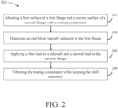
- a method 200 of coupling the shell 110 to the mating component 120 comprises abutting a first surface 111 of the first flange 112 and a second surface 113 of the second flange 114 with the mating component 120 (step 202).
- the first surface 111 and the second surface 113 may abut a single surface (e.g., a singular planar surface 122) of the mating component 120; however, the present disclosure is not limited in this regard.
- a singular planar surface 122 e.g., a singular planar surface 122
- a first surface 311 of a first flange 312 of a shell 310 may abut a first surface 321 of a mating component 320 and a second surface 313 of a second flange 314 of the shell 310 may abut a second surface 322 of the mating component (i.e., where the second surface 322 is in a different plane from the first surface 321) and still be within the scope of this disclosure.
- the method 200 further comprises disposing an end block 103 laterally adjacent to the first flange 112 (i.e., the flange where a load will not be applied) of the shell 110 (step 204).
- the first flange 112 could be oriented inward (i.e., into the cavity 102 from FIG. 1B ) and still be within the scope of this disclosure.
- the end block 103 would be disposed laterally adjacent to a sidewall 118 of the sidewalls 116.
- the end block 103 is configured to restrain lateral movement (i.e., movement in the -X direction) during vibration welding as described further herein.
- a lateral position of a weld line may remain constant during the welding process, in accordance with various embodiments.
- the method 200 further comprises applying a first load F1 to a sidewall 117 of the sidewalls 116 and a second load F2 to the second flange 114 (step 206).
- Each of the loads F1 and F2 may be at least generally directed toward the mating component 120.
- the first load F1 applied to the sidewall 117 may be substantially perpendicular to a plane defined by the sidewall 117.
- a plurality of local forces may be applied which may be substantially perpendicular to the sidewall 117 at a local point where the force is applied.
- substantially perpendicular as defined herein is between 60° and 90°, or between 70° and 90°, or between 80° and 90°.
- a contact surface of the sidewall 117 configured to receive the first load F1 may be substantially co-planar with the first surface 111 of the first flange 112.
- substantially co-planar as referred to herein is between 0° and 30°, or between 0° and 20°, or between 0° and 10°, in accordance with various embodiments.
- a load F3 may be applied substantially perpendicular to sidewall 317 and a load F4 may be applied substantially perpendicular to the second flange 314 during the method 200 for forming the hollow structure 300.
- the load applied to the sidewall e.g., a non-mating flange
- the load F3 supplied to sidewall 317 supplies a sufficient force, combined with an end block 103 from FIG. 1C positioned against the side of flange 312 and component 320 preventing lateral motion of the first flange 312, to join the first flange 312 to the mating component 320 during step 208 as described further herein.
- the method 200 further comprises vibrating the mating component 120 while keeping the shell 110 stationary (step 208).
- vibrating refers to translating a component (e.g., the mating component 120 or the shell 110) relative to the other component back and forth (e.g., oscillating) in a longitudinal direction (i.e., alternating between the Z direction and the -Z direction in FIG.
- a weld formed on the non-loaded flange may only be a partial lateral length (i.e., measured in the X direction from an adjacent sidewall) of the flange.
- a weld seam may be between 20% and 80% of a lateral length (i.e., in the X-direction) of a non-loaded flange, or between 20% and 60%, or between 25% and 50% by the method 200 disclosed herein.
- the entire flange of the non-loaded flange (e.g., first flange 112) may not weld to the mating component, the partial weld seam may be sufficient for loading of the hollow structure 100 from FIG. 1B .
- the torsional test data of a resultant hollow structures 100 formed via method 200 from FIG. 2 resulted in the hollow structure 100 buckling, and ultimately failing, prior to disbond of the weld seam formed from the method 200.
- the decrease in weight and cost of manufacturing the hollow structure 100 outweigh any reduction in structural capabilities of the weld formed by the method 200 disclosed herein.
- the weld formed on the loaded flange is between 90% and 100% of a lateral length of the flange.
- the weld formed on the loaded flange may be between 95% and 100% of a lateral length of the flange, or approximately an entire lateral length of the flange, in accordance with various embodiments.
- a flange e.g., first flange 112
- more complex hollow structures e.g., hollow structure 300 from FIG. 3
- a stiffening structure may be coupled to the first flange 112 and an adjacent sidewall 118 and/or a stiffening structure may be coupled to the flange 114 and an adjacent sidewall of the sidewalls 116.
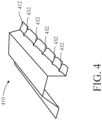
- a plurality of stiffening ridges 432 may be stamp formed into a first flange 412 of a shell 410 prior to performing the vibration welding method 200 from FIG. 2 .
- stiffening ribs 532 may be over molded or in-molded between a first flange 512 and an adjacent sidewall 515 of a shell 510 ( FIG. 5 ) or stiffening ribs 632 may be stamp formed into an adjacent sidewall 615 of a first flange 612 of a shell 610 ( FIG. 6 ) to further facilitate thinner shells being coupled to mating components as described herein.
Landscapes
- Engineering & Computer Science (AREA)
- Mechanical Engineering (AREA)
- Lining Or Joining Of Plastics Or The Like (AREA)
Description
- The present disclosure (invention) relates generally to systems and methods for vibration welding hollow structures, and more specifically to systems and methods for vibration welding without a direct load applied to an outer weld area for aircraft components.
- Aircraft are typically equipped with interior components and flight control surfaces. Flight control surfaces are utilized to maneuver the aircraft during flight as well as provide high lift surfaces to increase lift at low airspeed. Interior components vary significantly but often utilize hollow structures to reduce weight and decrease manufacturing costs. Vibration welding is utilized to couple a hollow structure to an adjacent component. Vibration welding operates at lower frequencies and higher amplitudes relative to ultrasonic welding. Additionally, a large clamping force is typically applied to each flange of a hollow structure that is being welded to an adj acent component.
-
JP 2017 100408 A - A method for forming a fiber-reinforced thermoplastic hollow structure according to an aspect of the invention is disclosed in claim 1. Embodiments of this aspect of the invention are provided in claims dependent from claim 1.
- A fiber-reinforced thermoplastic hollow structure according to an aspect of the invention is disclosed in claim 9. Embodiments of this aspect of the invention are provided in claims dependent from claim 9.
- The subject matter of the present disclosure is particularly pointed out and distinctly claimed in the concluding portion of the specification. A more complete understanding of the present disclosure, however, may best be obtained by referring to the detailed description and claims when considered in connection with the drawing figures, wherein like numerals denote like elements.
-
FIG. 1A illustrates a perspective view of a shell and a mating component prior to vibration welding, in accordance with various embodiments; -
FIG. 1B illustrates a perspective view of a shell and a mating component coupled together to form a hollow structure via vibration welding, in accordance with various embodiments; -
FIG. 1C illustrates a cross-sectional view of a shell and a mating component during vibration welding, in accordance with various embodiments; -
FIG. 2 illustrates a method of vibration welding, in accordance with various embodiments; -
FIG. 3 illustrates a perspective view of a shell and a mating component coupled together, in accordance with various embodiments; -
FIG. 4 illustrates a perspective view of a shell, in accordance with various embodiments; -
FIG. 5 illustrates a perspective view of a shell, in accordance with various embodiments; and -
FIG. 6 illustrates a perspective view of a shell, in accordance with various embodiments. - The detailed description of exemplary embodiments herein makes reference to the accompanying drawings, which show exemplary embodiments by way of illustration. While these exemplary embodiments are described in sufficient detail to enable those skilled in the art to practice the inventions, it should be understood that other embodiments may be realized and that logical changes and adaptations in design and construction may be made in accordance with this invention and the teachings herein. Thus, the detailed description herein is presented for purposes of illustration only and not for limitation. The scope of the invention is defined by the appended claims. For example, the steps recited in any of the method or process descriptions may be executed in any order and are not necessarily limited to the order presented. Furthermore, any reference to singular includes plural embodiments, and any reference to more than one component or step may include a singular embodiment or step. Also, any reference to attached, fixed, connected or the like may include permanent, removable, temporary, partial, full and/or any other possible attachment option. Additionally, any reference to without contact (or similar phrases) may also include reduced contact or minimal contact. Surface shading lines may be used throughout the figures to denote different parts but not necessarily to denote the same or different materials. In some cases, reference coordinates may be specific to each figure.
- In general, the example shells and mating components used to form a hollow structure as described herein may be used with control surfaces, such as aircraft wings, stabilizers, or elevators, among other aerodynamic surfaces of an aircraft. Some examples of common names for these surfaces known to those practiced in the arts include but are not limited to flaps, ailerons, rudders, elevators, stabilators, elevons, spoilers, lift dumpers, speed brakes, airbrakes, trim tabs, slats, flaperons, spoilerons, and canards. These are henceforth referred to as control surfaces. In general, control surfaces may direct air flow during maneuvering and in-flight aircraft attitude adjustments. The example control surfaces described herein may provide increased resistance to impact damage than some known control surface constructions. Further, the example methods for manufacturing control surfaces described herein include fewer and lighter components than some known control surfaces. Thus, the example control surfaces described herein provide increased fuel efficiency and/or range to aircraft. Still further, the example control surfaces may be manufactured using an automated skin/stiffener manufacturing process, as described herein, which optimizes material usage and reduces cycle time.
- Although described with respect to control surfaces, the present disclosure is not limited in this regard. For example, shells and mating components coupled together in accordance with the systems and methods disclosed herein may be used for aircraft interior components like seat backs, urban aerial mobility (UAM) components, or the like.
- A thermoplastic material including a fiber-reinforced structure, as described herein, includes a structural body comprising skin members. In various embodiments, the skin members include a continuous fiber reinforced fabric, or unidirectional tape based laminate, and a thermoplastic resin. The reinforcing fiber, or a combination of reinforcing fibers, to be used for the fiber-reinforced structure has no particular limitations with respect to the type thereof, and examples thereof include metal fibers, such as an aluminum fiber, a brass fiber, and a stainless steel fiber, carbon fibers (including graphite fibers), such as polyacrylonitrile (PAN)-based carbon fibers, rayon-based carbon fibers, lignin-based carbon fibers, and pitch-based carbon fibers, insulating fibers, such as glass fiber, organic fibers, such as aramid fibers, polyparaphenylene benzoxazole (PBO) fibers, polyphenylene sulfide fibers, polyester fibers, acrylic fibers, nylon fibers, and polyethylene fibers, and inorganic fibers, such as silicon carbide fibers and silicon nitride fibers. Fibers prepared by applying surface treatment to these fibers are also available. Examples of the surface treatment include treatment with a coupling agent, treatment with a sizing agent, treatment with a binder, and adhesion treatment with an additive in addition to deposition treatment with conductive metal.
- In the disclosure, the thermoplastic resin to be used for a mating component and/or a shell may be either semi-crystalline or amorphous.
- Examples of the semi-crystalline thermoplastic resin include polyester, polyolefin, polyoxymethylene (POM), polyamide (PA), polyarylene sulfide, polyketone (PK), polyetherketone (PEK), polyether ether ketone (PEEK), polyether ketone ketone (PEKK), polyvinylidene fluoride (PVDF), polytetrafluoroethylene (PTFE), polyaryletherketone (PAEK), polyether nitrile (PEN), fluororesin, and liquid crystal polymer (LCP). Examples of the polyester include polyethylene terephthalate (PET), polybutylene terephthalate (PBT), polytrimethylene terphthalate (PTT), polyethylene naphthalate (PEN), and liquid crystal polyester. Examples of the polyolefin include polyethylene (PE), polypropylene (PP), and polybutylene. Examples of the polyarylene sulfide include polyphenylene sulfide (PPS). Examples of the fluororesin include polytetrafluoroethylene.
- Examples of the amorphous thermoplastic resin include polystyrene, polycarbonate (PC), polymethyl methacrylate (PMMA), polyvinyl chloride (PVC), polyphenylene ether (PPE), polyimide (PI), polyamide imide (PAI), polyetherimide (PEI), polysulfone (PSU), polyether sulfone (PES), and polyarylate (PAR). The thermoplastic resin to be used for the control surface also may be phenoxy resin, polystyrene, polyolefin, polyurethane, polyester, polyamide, polybutadiene, polyisoprene, fluorine resin, acrylonitrile, and other thermoplastic elastomers, and copolymers and modified resin thereof.
- Disclosed herein is a method of vibration welding without applying a direct load to a flange that is welded to a mating component. The flange is an element of a shell being coupled to the mating component via vibration welding. The flange is compressed, via the method disclosed herein, from a nearby area, which generates a force on a weld area of the flange and the mating component sufficient to weld the flange to the mating component. In this regard, tooling costs may be reduced, a vibration welding process may be simplified, and/or a high weld strength between the flange and the mating component may be maintained.
- Referring now to
FIG. 1A , a perspective view of ashell 110 and amating component 120 prior to vibration welding is illustrated in accordance with various embodiments. In various embodiments, theshell 110 and themating component 120 both comprise a fiber reinforced thermoplastic material. Theshell 110 may be formed from a first continuous fiber reinforced fabric or uni-directional tape based laminate, as described herein. Themating component 120 may be formed from a second continuous fiber reinforced fabric, as described herein. In various embodiments, the second continuous fiber reinforced fabric is the same or similar material as the first continuous fiber reinforced fabric. In various embodiments, theshell 110 and/or themating component 120 may both be formed of multiple layers of fiber reinforced fabric. The present disclosure is not limited in this regard. In various embodiments, one of theshell 110 and themating component 120 may comprise a fiber-reinforced thermoplastic material and the remaining component may comprise any other material, such as a metal alloy (e.g., nickel-based alloy, titanium-based alloy, aluminum-based alloy, iron-based alloy, etc.). The present disclosure is not limited in this regard. - In various embodiments, the
shell 110 and themating component 120 may be formed by combining fiber fillers and thermoplastic resin at a pre-selected ratio to form a thermoplastic composite material with continuous fiber reinforcement. For example, theshell 110 and/ormating component 120 may be formed using automated fiber placement or automated tape laying. The pre-selected ratio may have any percentage or ratio of fiber filler to resin, such as 60% fiber filler and 40% resin. The mixture may range from 0% fiber filler and 100% resin to 80% fiber filler and 20% resin. In this regard,shell 110 and/or themating component 120 may be continuous fiber reinforced. However, it is contemplated herein thatshell 110 and themating component 120 may be discontinuous fiber reinforced, in accordance with various embodiments. - In various embodiments, the
shell 110 comprises afirst flange 112 and asecond flange 114. Thefirst flange 112 and thesecond flange 114 are configured to be vibration welded to themating component 120 without a direct load being applied to thefirst flange 112 as described further herein. - In various embodiments, the
shell 110 further comprisessidewalls 116. With reference now toFIG. 1B , internal surfaces of thesidewalls 116 and an internal surface of themating component 120 define acavity 102 of ahollow structure 100 in response to being coupled together via the systems and methods disclosed herein. Although illustrated as comprising perpendicular sidewalls to form a substantially square cross-section for thecavity 102, the present disclosure is not limited in this regard. For example, sidewalls 116 may comprise acute or obtuse angles and/or may define various types of cross-sections, such as trapezoidal, polygonal, hexagonal, or the like and still be within the scope of this disclosure. In various embodiments, each flange (e.g.,first flange 112 and second flange 114) extends laterally (i.e., in the X-direction) from an adjacent sidewall (e.g.,sidewall 118 forfirst flange 112 andsidewall 116 for flange 114). In various embodiments, a centerline through the cavity 102 (i.e., in the Z direction) may define a longitidudinal axis for thehollow structure 100 fromFIG. 1B . - Referring now to
FIG. 1C , asystem 101 for coupling theshell 110 to themating component 120 via vibration welding is illustrated, in accordance with various embodiments. With combined reference toFIGs. 1C and2 , amethod 200 of coupling theshell 110 to themating component 120 comprises abutting afirst surface 111 of thefirst flange 112 and asecond surface 113 of thesecond flange 114 with the mating component 120 (step 202). In various embodiments, thefirst surface 111 and thesecond surface 113 may abut a single surface (e.g., a singular planar surface 122) of themating component 120; however, the present disclosure is not limited in this regard. For example, with brief reference toFIG. 3 , afirst surface 311 of afirst flange 312 of ashell 310 may abut afirst surface 321 of amating component 320 and asecond surface 313 of asecond flange 314 of theshell 310 may abut asecond surface 322 of the mating component (i.e., where thesecond surface 322 is in a different plane from the first surface 321) and still be within the scope of this disclosure. - The
method 200 further comprises disposing anend block 103 laterally adjacent to the first flange 112 (i.e., the flange where a load will not be applied) of the shell 110 (step 204). Although illustrated as being disposed adjacent to thefirst flange 112, the present disclosure is not limited in this regard. For example, thefirst flange 112 could be oriented inward (i.e., into thecavity 102 fromFIG. 1B ) and still be within the scope of this disclosure. In this regard, theend block 103 would be disposed laterally adjacent to asidewall 118 of thesidewalls 116. Theend block 103 is configured to restrain lateral movement (i.e., movement in the -X direction) during vibration welding as described further herein. In this regard, a lateral position of a weld line may remain constant during the welding process, in accordance with various embodiments. - The
method 200 further comprises applying a first load F1 to asidewall 117 of thesidewalls 116 and a second load F2 to the second flange 114 (step 206). Each of the loads F1 and F2 may be at least generally directed toward themating component 120. In various embodiments, the first load F1 applied to thesidewall 117 may be substantially perpendicular to a plane defined by thesidewall 117. In various embodiments, in response to the plane defined by thesidewall 117 being contoured, a plurality of local forces may be applied which may be substantially perpendicular to thesidewall 117 at a local point where the force is applied. "Substantially perpendicular" as defined herein is between 60° and 90°, or between 70° and 90°, or between 80° and 90°. In various embodiments, a contact surface of thesidewall 117 configured to receive the first load F1 may be substantially co-planar with thefirst surface 111 of thefirst flange 112. "Substantially co-planar" as referred to herein is between 0° and 30°, or between 0° and 20°, or between 0° and 10°, in accordance with various embodiments. - Although illustrated as applying the first load F1 and the second load F2 in a similar direction, the present disclosure is not limited in this regard. For example, with brief reference to
FIG. 3 , a load F3 may be applied substantially perpendicular tosidewall 317 and a load F4 may be applied substantially perpendicular to thesecond flange 314 during themethod 200 for forming thehollow structure 300. In this regard, the load applied to the sidewall (e.g., a non-mating flange), may be substantially perpendicular to a mating surface of a non-loaded wall (e.g.,first surface 311 offirst flange 312. In this regard, the load F3 supplied to sidewall 317 supplies a sufficient force, combined with anend block 103 fromFIG. 1C positioned against the side offlange 312 andcomponent 320 preventing lateral motion of thefirst flange 312, to join thefirst flange 312 to themating component 320 duringstep 208 as described further herein. - The
method 200 further comprises vibrating themating component 120 while keeping theshell 110 stationary (step 208). Although described as vibrating themating component 120 relative to theshell 110, the present disclosure is not limited in this regard. For example, in various embodiments, theshell 110 may be vibrated while themating component 120 is kept stationary. In various embodiments, "vibrating" as described herein refers to translating a component (e.g., themating component 120 or the shell 110) relative to the other component back and forth (e.g., oscillating) in a longitudinal direction (i.e., alternating between the Z direction and the -Z direction inFIG. 1C ) to generate friction heat between thefirst surface 111 of thefirst flange 112 and themating component 120 and thesecond surface 113 of thesecond flange 114 and themating component 120. In this regard, the friction heat fuses at least a portion of thefirst surface 111 of thefirst flange 112 and thesecond surface 113 of thesecond flange 114 to themating component 120. - In various embodiments, a weld formed on the non-loaded flange (e.g., the first flange 112) may only be a partial lateral length (i.e., measured in the X direction from an adjacent sidewall) of the flange. For example, welding a
shell 110 with a flange length of 0.25 inches (0.635 cm) may result in a weld seam of approximately 0.10 inches (0.254 cm). In various embodiments, a weld seam may be between 20% and 80% of a lateral length (i.e., in the X-direction) of a non-loaded flange, or between 20% and 60%, or between 25% and 50% by themethod 200 disclosed herein. Although the entire flange of the non-loaded flange (e.g., first flange 112) may not weld to the mating component, the partial weld seam may be sufficient for loading of thehollow structure 100 fromFIG. 1B . For example, in some real cases the torsional test data of a resultanthollow structures 100 formed viamethod 200 fromFIG. 2 resulted in thehollow structure 100 buckling, and ultimately failing, prior to disbond of the weld seam formed from themethod 200. In this regard, the decrease in weight and cost of manufacturing thehollow structure 100 outweigh any reduction in structural capabilities of the weld formed by themethod 200 disclosed herein. In contrast to the non-loaded flange, the weld formed on the loaded flange (e.g., the second flange 114) is between 90% and 100% of a lateral length of the flange. For example, the weld formed on the loaded flange may be between 95% and 100% of a lateral length of the flange, or approximately an entire lateral length of the flange, in accordance with various embodiments. - In various embodiments, by not having to apply a direct load to a flange (e.g., first flange 112) that is being friction welded to a
mating component 120, more complex hollow structures (e.g.,hollow structure 300 fromFIG. 3 ) may be manufactured in a simpler manner and/or at a lower expense relative to typical vibration welding processes. - In various embodiments, to further facilitate thinner shells being coupled to mating components, a stiffening structure may be coupled to the
first flange 112 and anadjacent sidewall 118 and/or a stiffening structure may be coupled to theflange 114 and an adjacent sidewall of thesidewalls 116. For example, with reference now toFIG. 4 , a plurality of stiffeningridges 432 may be stamp formed into afirst flange 412 of ashell 410 prior to performing thevibration welding method 200 fromFIG. 2 . With reference now toFIGs. 5 and 6 , stiffeningribs 532 may be over molded or in-molded between afirst flange 512 and anadjacent sidewall 515 of a shell 510 (FIG. 5 ) or stiffeningribs 632 may be stamp formed into anadjacent sidewall 615 of afirst flange 612 of a shell 610 (FIG. 6 ) to further facilitate thinner shells being coupled to mating components as described herein.
Claims (12)
- A method for forming a fiber-reinforced thermoplastic hollow structure (100; 300), comprising:abutting a first surface (111; 311) of a first flange (112; 312; 412; 512; 612) of a shell (110; 310; 410; 510; 610) and a second surface (113; 313) of a second flange (114; 314) of the shell (110; 310; 410; 510; 610) with a mating component (120; 320);configuring an end block (103) to restrain lateral movement of the shell (110; 310; 410; 510; 610);applying a first load (F1) to a sidewall (118; 117; 317) of the shell (110; 310; 410; 510; 610);applying a second load (F2) to the second flange (114; 314) of the shell (110; 310; 410; 510; 610); andvibrating one of the shell (110; 310; 410; 510; 610) or the mating component (120; 320) while keeping a non-vibrating component (320) stationary, the non-vibrating component (320) including one of the shell (110; 310; 410; 510; 610) or the mating component (120; 320) the method characterised in that a direct load is not applied to the first flange (112; 312; 412; 512; 612).
- The method of claim 1, wherein the vibrating generates heat between the first surface (111; 311) of the first flange (112; 312; 412; 512; 612) and the mating component (120; 320) and generates heat between the second surface (113; 313) of the second flange (114; 314) and the mating component (120; 320).
- The method of any preceding claim, wherein the vibrating forms a weld seam between the first flange (112; 312; 412; 512; 612) and the mating component (120; 320).
- The method of claim 3, wherein a lateral length of the weld seam is between 20% and 80% of a lateral length of the first flange (112; 312; 412; 512; 612).
- The method of any preceding claim, wherein the shell (110; 310; 410; 510; 610) comprises a fiber-reinforced thermoplastic material including continuous fibers.
- The method of any preceding claim, further comprising stamp forming a plurality of ridges into the first flange (112; 312; 412; 512; 612) prior to the abutting.
- The method of any preceding claim, further comprising one of over molding or insert molding stiffening members between the first flange (112; 312; 412; 512; 612) and an adjacent sidewall (118; 515; 615) of the first flange (112; 312; 412; 512; 612) prior to the abutting.
- The method of any preceding claim, further comprising stamp forming stiffening ribs (532; 632) into an adjacent sidewall (515; 615) of the first flange (112; 312; 412; 512; 612) prior to the abutting.
- A fiber-reinforced thermoplastic hollow structure (100; 300), comprising:a shell (110; 310; 410; 510; 610) comprising a first flange (112; 312; 412; 512; 612), a second flange (114; 314), and sidewalls (116), the shell (110; 310; 410; 510; 610) comprising a fiber-reinforced thermoplastic material; anda mating component (120; 320) coupled to the first flange (112; 312; 412; 512; 612) and the second flange (114; 314) and including a first internal surface, and the first internal surface and internal surfaces of the sidewalls (116) defining a cavity (102), the first flange (112; 312; 412; 512; 612) and the mating component (120; 320) defining a first weld seam, the second flange (114; 314) and the mating component (120; 320) define a second weld seam, wherein: a lateral length of the second weld seam is between 90% and 100% of a lateral length of the second flange (114; 314), and characterised in that
a lateral length of the first weld seam is between 20% and 80% of a lateral length of the first flange (112; 312; 412; 512; 612). - The fiber-reinforced thermoplastic hollow structure (100; 300) of claim 9, wherein the lateral length of the first weld seam is between 20% and 60% of the lateral length of the first flange (112; 312; 412; 512; 612).
- The fiber-reinforced thermoplastic hollow structure (100; 300) of claims 9 or 10, wherein at least one of the first flange (112; 312; 412; 512; 612) and the second flange (114; 314) further comprises a plurality of stiffening ridges (432).
- The fiber-reinforced thermoplastic hollow structure of any of claims 9 to 11, further comprising stiffening ribs (532; 632) disposed at least one of between the first flange (112; 312; 412; 512; 612) and an adjacent sidewall (118; 515; 615) and between the second flange (114; 314) and an adjacent sidewall (118; 515; 615) in the sidewalls (116) of the shell (110; 310; 410; 510; 610).
Priority Applications (1)
| Application Number | Priority Date | Filing Date | Title |
|---|---|---|---|
| EP24215601.6A EP4491381A3 (en) | 2021-12-17 | 2022-12-09 | Vibration welding systems and methods |
Applications Claiming Priority (1)
| Application Number | Priority Date | Filing Date | Title |
|---|---|---|---|
| US17/554,137 US11731369B2 (en) | 2021-12-17 | 2021-12-17 | Vibration welding systems and methods |
Related Child Applications (1)
| Application Number | Title | Priority Date | Filing Date |
|---|---|---|---|
| EP24215601.6A Division EP4491381A3 (en) | 2021-12-17 | 2022-12-09 | Vibration welding systems and methods |
Publications (2)
| Publication Number | Publication Date |
|---|---|
| EP4209334A1 EP4209334A1 (en) | 2023-07-12 |
| EP4209334B1 true EP4209334B1 (en) | 2024-11-27 |
Family
ID=84487829
Family Applications (2)
| Application Number | Title | Priority Date | Filing Date |
|---|---|---|---|
| EP22212647.6A Active EP4209334B1 (en) | 2021-12-17 | 2022-12-09 | Vibration welding system and method |
| EP24215601.6A Pending EP4491381A3 (en) | 2021-12-17 | 2022-12-09 | Vibration welding systems and methods |
Family Applications After (1)
| Application Number | Title | Priority Date | Filing Date |
|---|---|---|---|
| EP24215601.6A Pending EP4491381A3 (en) | 2021-12-17 | 2022-12-09 | Vibration welding systems and methods |
Country Status (2)
| Country | Link |
|---|---|
| US (1) | US11731369B2 (en) |
| EP (2) | EP4209334B1 (en) |
Families Citing this family (1)
| Publication number | Priority date | Publication date | Assignee | Title |
|---|---|---|---|---|
| US12157277B2 (en) * | 2021-12-30 | 2024-12-03 | Rohr, Inc. | Vibration welding fiber-reinforced composite aircraft structures |
Family Cites Families (9)
| Publication number | Priority date | Publication date | Assignee | Title |
|---|---|---|---|---|
| US4352711A (en) * | 1981-06-15 | 1982-10-05 | Branson Ultrasonics Corporation | Friction welding apparatus |
| US4601927A (en) | 1984-05-11 | 1986-07-22 | Hydroacoustics, Inc. | Welding of plastic parts |
| CA2544872C (en) | 2003-11-04 | 2009-08-11 | Bystronic Solution Centre Inc. | A framed panel and related method of manufacture |
| US20090104399A1 (en) * | 2006-05-15 | 2009-04-23 | Stephen Field | Vibration welded joint structures, methods, and apparatus for thermoplastic members |
| DE502006007191D1 (en) | 2006-12-12 | 2010-07-22 | Branson Ultraschall | Method and device for producing mitred corner joints by vibration welding |
| DE102011053100A1 (en) * | 2011-08-30 | 2013-02-28 | Rehau Ag + Co | Two-wheeler frame, two-wheeler and method of manufacturing a bicycle frame |
| JP2017100408A (en) | 2015-12-04 | 2017-06-08 | トヨタ自動車株式会社 | Manufacturing method for bonded body |
| DE102018102784B4 (en) | 2018-02-08 | 2023-09-21 | Valeo Schalter Und Sensoren Gmbh | Method and device for connecting two components and their use |
| KR102543535B1 (en) * | 2021-02-09 | 2023-06-16 | 현대모비스 주식회사 | Side mounting seat of PAB chute having reinforced weldability and PAB chute manufacturing method |
-
2021
- 2021-12-17 US US17/554,137 patent/US11731369B2/en active Active
-
2022
- 2022-12-09 EP EP22212647.6A patent/EP4209334B1/en active Active
- 2022-12-09 EP EP24215601.6A patent/EP4491381A3/en active Pending
Also Published As
| Publication number | Publication date |
|---|---|
| US20230330943A1 (en) | 2023-10-19 |
| US20230191708A1 (en) | 2023-06-22 |
| EP4491381A2 (en) | 2025-01-15 |
| EP4209334A1 (en) | 2023-07-12 |
| US11731369B2 (en) | 2023-08-22 |
| EP4491381A3 (en) | 2025-03-26 |
Similar Documents
| Publication | Publication Date | Title |
|---|---|---|
| US11926110B2 (en) | Thermoplastic composite panel systems and methods | |
| KR101846592B1 (en) | Method and system of making composite structures having gap fillers with chopped fiber material | |
| EP1868795B1 (en) | Multi-axial laminate composite structures | |
| US8333345B2 (en) | Composite aircraft joint | |
| US10220935B2 (en) | Open-channel stiffener | |
| US7968169B2 (en) | Compound contoured composite beams and fabrication methods | |
| US20130020438A1 (en) | Flexible Truss Frame and Method of Making the Same | |
| US20030196741A1 (en) | Textile joint reinforcement and associated method | |
| GB2542238A (en) | Methods of making and structures containing stiffeners having transition portions | |
| US8234901B2 (en) | Method to create bends in composite panels | |
| US10507931B2 (en) | Panel and insert for corner radii | |
| EP4209334A1 (en) | Vibration welding systems and methods | |
| US20170043859A1 (en) | Trailing edge components, aircraft structures including trailing edge components and methods for manufacturing trailing edge components | |
| US12629896B2 (en) | Vibration welding systems and methods | |
| EP4144515A1 (en) | Thermoplastic composite panel with corrugated peaks and troughs stiffening systems and methods | |
| EP2836760B1 (en) | Composite tank having joint with softening strip and method of making the tank | |
| CN108386427A (en) | Insertion piece for joint element | |
| EP4215344B1 (en) | Vibration welding fiber-reinforced composite aircraft structures | |
| US12351305B2 (en) | Thermoplastic composite structure and methods for forming | |
| EP4596220A1 (en) | Compliant consolidation block for continuous welding of polymer matrix composites | |
| US11377851B2 (en) | Stringer and associated composite structure and method for reinforcing a base structure | |
| EP4299292A1 (en) | Vibration welding method and system | |
| EP4015360B1 (en) | Circumferential lap splices for sections of fuselage | |
| US20230321928A1 (en) | Composite part with crossbeam supports and methods of forming composite parts | |
| AU2019263784B2 (en) | Composite structural elements |
Legal Events
| Date | Code | Title | Description |
|---|---|---|---|
| PUAI | Public reference made under article 153(3) epc to a published international application that has entered the european phase |
Free format text: ORIGINAL CODE: 0009012 |
|
| STAA | Information on the status of an ep patent application or granted ep patent |
Free format text: STATUS: THE APPLICATION HAS BEEN PUBLISHED |
|
| AK | Designated contracting states |
Kind code of ref document: A1 Designated state(s): AL AT BE BG CH CY CZ DE DK EE ES FI FR GB GR HR HU IE IS IT LI LT LU LV MC ME MK MT NL NO PL PT RO RS SE SI SK SM TR |
|
| STAA | Information on the status of an ep patent application or granted ep patent |
Free format text: STATUS: REQUEST FOR EXAMINATION WAS MADE |
|
| 17P | Request for examination filed |
Effective date: 20240111 |
|
| RBV | Designated contracting states (corrected) |
Designated state(s): AL AT BE BG CH CY CZ DE DK EE ES FI FR GB GR HR HU IE IS IT LI LT LU LV MC ME MK MT NL NO PL PT RO RS SE SI SK SM TR |
|
| GRAP | Despatch of communication of intention to grant a patent |
Free format text: ORIGINAL CODE: EPIDOSNIGR1 |
|
| STAA | Information on the status of an ep patent application or granted ep patent |
Free format text: STATUS: GRANT OF PATENT IS INTENDED |
|
| INTG | Intention to grant announced |
Effective date: 20240619 |
|
| GRAS | Grant fee paid |
Free format text: ORIGINAL CODE: EPIDOSNIGR3 |
|
| GRAA | (expected) grant |
Free format text: ORIGINAL CODE: 0009210 |
|
| STAA | Information on the status of an ep patent application or granted ep patent |
Free format text: STATUS: THE PATENT HAS BEEN GRANTED |
|
| AK | Designated contracting states |
Kind code of ref document: B1 Designated state(s): AL AT BE BG CH CY CZ DE DK EE ES FI FR GB GR HR HU IE IS IT LI LT LU LV MC ME MK MT NL NO PL PT RO RS SE SI SK SM TR |
|
| REG | Reference to a national code |
Ref country code: GB Ref legal event code: FG4D |
|
| REG | Reference to a national code |
Ref country code: CH Ref legal event code: EP |
|
| REG | Reference to a national code |
Ref country code: IE Ref legal event code: FG4D |
|
| REG | Reference to a national code |
Ref country code: DE Ref legal event code: R096 Ref document number: 602022008164 Country of ref document: DE |
|
| REG | Reference to a national code |
Ref country code: LT Ref legal event code: MG9D |
|
| REG | Reference to a national code |
Ref country code: NL Ref legal event code: MP Effective date: 20241127 |
|
| PG25 | Lapsed in a contracting state [announced via postgrant information from national office to epo] |
Ref country code: PT Free format text: LAPSE BECAUSE OF FAILURE TO SUBMIT A TRANSLATION OF THE DESCRIPTION OR TO PAY THE FEE WITHIN THE PRESCRIBED TIME-LIMIT Effective date: 20250327 Ref country code: IS Free format text: LAPSE BECAUSE OF FAILURE TO SUBMIT A TRANSLATION OF THE DESCRIPTION OR TO PAY THE FEE WITHIN THE PRESCRIBED TIME-LIMIT Effective date: 20250327 Ref country code: HR Free format text: LAPSE BECAUSE OF FAILURE TO SUBMIT A TRANSLATION OF THE DESCRIPTION OR TO PAY THE FEE WITHIN THE PRESCRIBED TIME-LIMIT Effective date: 20241127 |
|
| PG25 | Lapsed in a contracting state [announced via postgrant information from national office to epo] |
Ref country code: FI Free format text: LAPSE BECAUSE OF FAILURE TO SUBMIT A TRANSLATION OF THE DESCRIPTION OR TO PAY THE FEE WITHIN THE PRESCRIBED TIME-LIMIT Effective date: 20241127 Ref country code: NL Free format text: LAPSE BECAUSE OF FAILURE TO SUBMIT A TRANSLATION OF THE DESCRIPTION OR TO PAY THE FEE WITHIN THE PRESCRIBED TIME-LIMIT Effective date: 20241127 |
|
| REG | Reference to a national code |
Ref country code: AT Ref legal event code: MK05 Ref document number: 1745327 Country of ref document: AT Kind code of ref document: T Effective date: 20241127 |
|
| PG25 | Lapsed in a contracting state [announced via postgrant information from national office to epo] |
Ref country code: BG Free format text: LAPSE BECAUSE OF FAILURE TO SUBMIT A TRANSLATION OF THE DESCRIPTION OR TO PAY THE FEE WITHIN THE PRESCRIBED TIME-LIMIT Effective date: 20241127 |
|
| PG25 | Lapsed in a contracting state [announced via postgrant information from national office to epo] |
Ref country code: ES Free format text: LAPSE BECAUSE OF FAILURE TO SUBMIT A TRANSLATION OF THE DESCRIPTION OR TO PAY THE FEE WITHIN THE PRESCRIBED TIME-LIMIT Effective date: 20241127 |
|
| PG25 | Lapsed in a contracting state [announced via postgrant information from national office to epo] |
Ref country code: NO Free format text: LAPSE BECAUSE OF FAILURE TO SUBMIT A TRANSLATION OF THE DESCRIPTION OR TO PAY THE FEE WITHIN THE PRESCRIBED TIME-LIMIT Effective date: 20250227 |
|
| PG25 | Lapsed in a contracting state [announced via postgrant information from national office to epo] |
Ref country code: GR Free format text: LAPSE BECAUSE OF FAILURE TO SUBMIT A TRANSLATION OF THE DESCRIPTION OR TO PAY THE FEE WITHIN THE PRESCRIBED TIME-LIMIT Effective date: 20250228 Ref country code: LV Free format text: LAPSE BECAUSE OF FAILURE TO SUBMIT A TRANSLATION OF THE DESCRIPTION OR TO PAY THE FEE WITHIN THE PRESCRIBED TIME-LIMIT Effective date: 20241127 Ref country code: AT Free format text: LAPSE BECAUSE OF FAILURE TO SUBMIT A TRANSLATION OF THE DESCRIPTION OR TO PAY THE FEE WITHIN THE PRESCRIBED TIME-LIMIT Effective date: 20241127 |
|
| PG25 | Lapsed in a contracting state [announced via postgrant information from national office to epo] |
Ref country code: PL Free format text: LAPSE BECAUSE OF FAILURE TO SUBMIT A TRANSLATION OF THE DESCRIPTION OR TO PAY THE FEE WITHIN THE PRESCRIBED TIME-LIMIT Effective date: 20241127 |
|
| PG25 | Lapsed in a contracting state [announced via postgrant information from national office to epo] |
Ref country code: RS Free format text: LAPSE BECAUSE OF FAILURE TO SUBMIT A TRANSLATION OF THE DESCRIPTION OR TO PAY THE FEE WITHIN THE PRESCRIBED TIME-LIMIT Effective date: 20250227 |
|
| PG25 | Lapsed in a contracting state [announced via postgrant information from national office to epo] |
Ref country code: SM Free format text: LAPSE BECAUSE OF FAILURE TO SUBMIT A TRANSLATION OF THE DESCRIPTION OR TO PAY THE FEE WITHIN THE PRESCRIBED TIME-LIMIT Effective date: 20241127 |
|
| PG25 | Lapsed in a contracting state [announced via postgrant information from national office to epo] |
Ref country code: DK Free format text: LAPSE BECAUSE OF FAILURE TO SUBMIT A TRANSLATION OF THE DESCRIPTION OR TO PAY THE FEE WITHIN THE PRESCRIBED TIME-LIMIT Effective date: 20241127 |
|
| PG25 | Lapsed in a contracting state [announced via postgrant information from national office to epo] |
Ref country code: EE Free format text: LAPSE BECAUSE OF FAILURE TO SUBMIT A TRANSLATION OF THE DESCRIPTION OR TO PAY THE FEE WITHIN THE PRESCRIBED TIME-LIMIT Effective date: 20241127 |
|
| PG25 | Lapsed in a contracting state [announced via postgrant information from national office to epo] |
Ref country code: RO Free format text: LAPSE BECAUSE OF FAILURE TO SUBMIT A TRANSLATION OF THE DESCRIPTION OR TO PAY THE FEE WITHIN THE PRESCRIBED TIME-LIMIT Effective date: 20241127 |
|
| PG25 | Lapsed in a contracting state [announced via postgrant information from national office to epo] |
Ref country code: SK Free format text: LAPSE BECAUSE OF FAILURE TO SUBMIT A TRANSLATION OF THE DESCRIPTION OR TO PAY THE FEE WITHIN THE PRESCRIBED TIME-LIMIT Effective date: 20241127 |
|
| PG25 | Lapsed in a contracting state [announced via postgrant information from national office to epo] |
Ref country code: CZ Free format text: LAPSE BECAUSE OF FAILURE TO SUBMIT A TRANSLATION OF THE DESCRIPTION OR TO PAY THE FEE WITHIN THE PRESCRIBED TIME-LIMIT Effective date: 20241127 |
|
| PG25 | Lapsed in a contracting state [announced via postgrant information from national office to epo] |
Ref country code: IT Free format text: LAPSE BECAUSE OF FAILURE TO SUBMIT A TRANSLATION OF THE DESCRIPTION OR TO PAY THE FEE WITHIN THE PRESCRIBED TIME-LIMIT Effective date: 20241127 |
|
| PG25 | Lapsed in a contracting state [announced via postgrant information from national office to epo] |
Ref country code: LU Free format text: LAPSE BECAUSE OF NON-PAYMENT OF DUE FEES Effective date: 20241209 |
|
| REG | Reference to a national code |
Ref country code: DE Ref legal event code: R097 Ref document number: 602022008164 Country of ref document: DE |
|
| PG25 | Lapsed in a contracting state [announced via postgrant information from national office to epo] |
Ref country code: SE Free format text: LAPSE BECAUSE OF FAILURE TO SUBMIT A TRANSLATION OF THE DESCRIPTION OR TO PAY THE FEE WITHIN THE PRESCRIBED TIME-LIMIT Effective date: 20241127 |
|
| PG25 | Lapsed in a contracting state [announced via postgrant information from national office to epo] |
Ref country code: MC Free format text: LAPSE BECAUSE OF FAILURE TO SUBMIT A TRANSLATION OF THE DESCRIPTION OR TO PAY THE FEE WITHIN THE PRESCRIBED TIME-LIMIT Effective date: 20241127 |
|
| PLBE | No opposition filed within time limit |
Free format text: ORIGINAL CODE: 0009261 |
|
| STAA | Information on the status of an ep patent application or granted ep patent |
Free format text: STATUS: NO OPPOSITION FILED WITHIN TIME LIMIT |
|
| REG | Reference to a national code |
Ref country code: BE Ref legal event code: MM Effective date: 20241231 |
|
| PG25 | Lapsed in a contracting state [announced via postgrant information from national office to epo] |
Ref country code: BE Free format text: LAPSE BECAUSE OF NON-PAYMENT OF DUE FEES Effective date: 20241231 |
|
| PG25 | Lapsed in a contracting state [announced via postgrant information from national office to epo] |
Ref country code: IE Free format text: LAPSE BECAUSE OF NON-PAYMENT OF DUE FEES Effective date: 20241209 |
|
| 26N | No opposition filed |
Effective date: 20250828 |
|
| PGFP | Annual fee paid to national office [announced via postgrant information from national office to epo] |
Ref country code: DE Payment date: 20251126 Year of fee payment: 4 |
|
| PGFP | Annual fee paid to national office [announced via postgrant information from national office to epo] |
Ref country code: FR Payment date: 20251120 Year of fee payment: 4 |
|
| PG25 | Lapsed in a contracting state [announced via postgrant information from national office to epo] |
Ref country code: CY Free format text: LAPSE BECAUSE OF FAILURE TO SUBMIT A TRANSLATION OF THE DESCRIPTION OR TO PAY THE FEE WITHIN THE PRESCRIBED TIME-LIMIT Effective date: 20241127 |