EP4209290B1 - Low-pressure aluminum casting mold and low-pressure aluminum casting process for motor rotor - Google Patents
Low-pressure aluminum casting mold and low-pressure aluminum casting process for motor rotor Download PDFInfo
- Publication number
- EP4209290B1 EP4209290B1 EP22841224.3A EP22841224A EP4209290B1 EP 4209290 B1 EP4209290 B1 EP 4209290B1 EP 22841224 A EP22841224 A EP 22841224A EP 4209290 B1 EP4209290 B1 EP 4209290B1
- Authority
- EP
- European Patent Office
- Prior art keywords
- pressure
- rotor core
- low
- mold
- rotor
- Prior art date
- Legal status (The legal status is an assumption and is not a legal conclusion. Google has not performed a legal analysis and makes no representation as to the accuracy of the status listed.)
- Active
Links
Images


Classifications
-
- B—PERFORMING OPERATIONS; TRANSPORTING
- B22—CASTING; POWDER METALLURGY
- B22D—CASTING OF METALS; CASTING OF OTHER SUBSTANCES BY THE SAME PROCESSES OR DEVICES
- B22D18/00—Pressure casting; Vacuum casting
- B22D18/04—Low pressure casting, i.e. making use of pressures up to a few bars to fill the mould
-
- B—PERFORMING OPERATIONS; TRANSPORTING
- B22—CASTING; POWDER METALLURGY
- B22D—CASTING OF METALS; CASTING OF OTHER SUBSTANCES BY THE SAME PROCESSES OR DEVICES
- B22D19/00—Casting in, on, or around objects which form part of the product
- B22D19/0054—Casting in, on, or around objects which form part of the product rotors, stators for electrical motors
-
- B—PERFORMING OPERATIONS; TRANSPORTING
- B22—CASTING; POWDER METALLURGY
- B22D—CASTING OF METALS; CASTING OF OTHER SUBSTANCES BY THE SAME PROCESSES OR DEVICES
- B22D33/00—Equipment for handling moulds
- B22D33/04—Bringing together or separating moulds
-
- B—PERFORMING OPERATIONS; TRANSPORTING
- B21—MECHANICAL METAL-WORKING WITHOUT ESSENTIALLY REMOVING MATERIAL; PUNCHING METAL
- B21D—WORKING OR PROCESSING OF SHEET METAL OR METAL TUBES, RODS OR PROFILES WITHOUT ESSENTIALLY REMOVING MATERIAL; PUNCHING METAL
- B21D28/00—Shaping by press-cutting; Perforating
- B21D28/02—Punching blanks or articles with or without obtaining scrap; Notching
- B21D28/22—Notching the peripheries of circular blanks, e.g. laminations for dynamo-electric machines
Definitions
- the present invention belongs to the technical field of low-pressure aluminium casting, and particularly relates to a low-pressure aluminium casting mold and low-pressure aluminium casting process for motor rotor.
- Low-pressure aluminium casting is such a casting method that makes molten aluminium fill and solidify in the mold cavity under the action of low-pressure so as to obtain high-quality castings. It has high production efficiency and thus is widely used.
- CN212371156U discloses a high-voltage-motor aluminum casting rotor mold based on low-pressure aluminium casting, comprising an upper mold, a lower mold, an iron core, and a dummy shaft.
- the dummy shaft includes a dummy shaft cover, a shaft body and a dummy shaft bottom cover.
- the upper and lower ends of the iron core are respectively provided with an upper cover plate and a lower cover plate which can cover the vent holes of the punching sheet.
- the high-voltage-motor aluminum casting rotor mold also comprises a pressing device, which includes a pressing cylinder and an eye bolt.
- US2996773A discloses a method of casting a winding in a rotor for a dynamoelectric machine, which comprises the steps of assembling a plurality of laminations having conductor slots therein to form a magnetic core, placing said core between a pair of iron molds and exerting an inward force thereon to compress the laminations by direct contact with the molds, said molds having cavities shaped to the configuration of fan blades and end rings and arranged for communication with said conductor slots, pouring molten aluminum into a central bore provided in said core and permitting the aluminum to flow outwardly into said cavities and the conductor slots formed in the laminations, venting air from said cavities and slots as pouring progresses, and removing said molds and excess aluminum from the rotor bore when all the cavities and conductor slots are filled with aluminum.
- the present invention provides a low-pressure aluminium casting mold and a low-pressure aluminium casting process for motor rotor, and solves the technical problems in the traditional low-pressure aluminium casting process and mold such as hidden dangers of aluminium leakage, poor ventilation and heat dissipation of the motor, reduction of the success rate of aluminium casting of the motor rotor.
- a low-pressure aluminium casting mold for motor rotor which includes an upper backing plate and an upper mold, a lower backing plate and a lower mold, a rotor core, a dummy shaft and a diverter, wherein; the dummy shaft includes a vertically arranged shaft body, a dummy shaft upper cover arranged at the upper part of the shaft body, and a dummy shaft lower cover arranged at the lower part of the shaft body; the diverter is arranged between the dummy shaft and the lower mold, wherein:
- the area of the horizontal cross section of the clamping slot is larger than that of the U-shaped hole.
- chamfers are arranged at the outer edge of the bottom surface of the circular cover plate, the outer edge of the bottom surface of the diverter, the bottom edge of the cover plate placing groove and the bottom edge of the second through hole.
- a low-pressure aluminium casting process for motor rotor implemented using a low-pressure aluminium casting mold for motor rotor
- the low-pressure aluminium casting mold for motor rotor includes an upper backing plate and an upper mold, a lower backing plate and a lower mold, a rotor core, a dummy shaft, a diverter, a first pressing device and four sets of second pressing devices
- the dummy shaft includes a vertically arranged shaft body, a dummy shaft upper cover arranged at the upper part of the shaft body, and a dummy shaft lower cover arranged at the lower part of the shaft body
- the diverter is arranged between the dummy shaft and the lower mold
- the first pressing device is arranged at the top of the dummy shaft to press the middle part of the rotor core
- the four sets of second pressing devices are arranged at four corner positions of the low-pressure aluminium casting mold
- the middle parts of the four corners of the lower backing plate are respectively provided with horizontal clamping slots and U-shaped
- the second specified length of the rotor core in hot lamination is 1.013 times of the first specified length of the rotor core in cold lamination.
- the pressure parameters of low-pressure aluminium casting are controlled as follows:
- the low-pressure aluminium casting mold for motor rotor has the following beneficial effects:
- the compression of the first pressing device and the second pressing device ensures the lamination compactness of the rotor core, thoroughly eliminates the hidden danger of aluminium leakage in the aluminium casting process of the rotor, improves the success rate of aluminium casting of the motor rotor, ensures the quality of the cast-aluminium rotor, and has the advantages of simple process and low cost.
- the second pressing device fastens the upper backing plate and the lower backing plate through the pull rod, which realizes the pressing of the upper and lower molds and the rotor core. It has simple structure and there is no need to add complicated pressing equipment for compression. The operation and adjustment are convenient and the operation efficiency is also improved.
- the downward-bulged arc protrusion arranged at the center of the bottom surface of the diverter makes the distribution of molten aluminium more uniform and thus improves the casting quality.
- the low-pressure aluminium casting process for motor rotor has the following beneficial effects: Through the cold lamination and hot lamination together with the double compression of the first pressing device and the second pressing device, the lamination compactness of the rotor core is ensured, the hidden danger of aluminium leakage in the aluminium casting process of the rotor is completely eliminated, the success rate of aluminium casting of motor rotor is improved, and the quality of the cast-aluminium rotor is guaranteed. Moreover, it has the advantages of simple process and low cost.
- the upper backing plate and the lower backing plate can be fastened to each other through the pull rod of the second pressing device, thus realizing the pressing of the upper and lower molds and the rotor core.
- the low-pressure aluminium casting mold for motor rotor of the present invention includes an upper blade profile assembly, a lower blade profile assembly, a rotor core 1, a dummy shaft 2 and a diverter 7.
- the upper blade profile assembly includes an upper backing plate 3 and an upper mold 4, and the lower blade profile assembly includes a lower backing plate 5 and a lower mold 6.
- the dummy shaft 2 includes a vertically arranged shaft body 2-1, a dummy shaft upper cover 2-2 arranged at the upper part of the shaft body 2-1, and a dummy shaft lower cover 2-3 arranged at the lower part of the shaft body 2-1.
- the diverter 7 is arranged between the dummy shaft 2 and the lower mold 6.
- the low-pressure aluminium casting mold further includes a first pressing device 8 and four sets of second pressing devices 9, wherein the first pressing device 8 is arranged at the top of the dummy shaft 2 to press the middle part of the rotor core 1, and the four sets of second pressing devices 9 are arranged at four corner positions of the low-pressure aluminium casting mold.
- the middle parts of the four corners of the lower backing plate 5 are respectively provided with horizontal clamping slots 5-1 and U-shaped holes 5-2, the U-shaped hole 5-2 is provided on the lower backing plate 5 and above the clamping slot 5-1, the opening of the U-shaped hole 5-2 faces the outside, and the position of the upper backing plate 3 corresponding to the U-shaped hole 5-2 is provided with a hold-down through hole 3-1.
- the second pressing device 9 includes a pull rod 9-1, a clamping plate 9-2 and a hold-down nut 9-3, wherein the clamping plate 9-2 is arranged in the clamping slot 5-1; the pull rod 9-1 is vertically arranged, and the bottom end of the pull rod 9-1 passes through the U-shaped hole 5-2 and is connected with the top surface of the clamping plate 9-2; the outer wall of the upper section of the pull rod 9-1 is provided with external threads; the top end of the pull rod 9-1 passes through the corresponding hold-down through hole 3-1; and the hold-down nut 9-3 is connected with the external threads on the pull rod 9-1 by threads.
- the area of the horizontal cross section of the clamping slot 5-1 is larger than that of the U-shaped hole 5-2, thereby limiting the clamping plate 9-2 to prevent the clamping plate 9-2 from falling off in the fastening process.
- the first pressing device 8 includes a pressing cover 8-1 and an eyebolt 8-2.
- the pressing cover 8-1 is a cylindrical tube structure with an open bottom and is coaxially covered on the top of the dummy shaft 2, and the bottom edge of the pressing cover 8-1 is pressed on the top surface of the rotor core 1.
- the middle part of the dummy shaft upper cover 2-2 is provided with a first threaded hole 2-2-1
- the top surface of the pressing cover 8-1 is provided with a second threaded hole 8-1-1
- the lower end of the eyebolt 8-2 passes through the second threaded hole 8-1-1 and is connected with the first threaded hole 2-2-1.
- the first pressing device 8 presses the rotor core 1 with the pressing cover 8-1 by tightening the eyebolt 8-2.
- the middle part of the shaft body 2-1 is vertically provided with a first through hole 2-1-1, the bottom end of the first through hole 2-1-1 is coaxially provided with an annular clamping slot 2-1-2, and the inner diameter of the annular clamping slot 2-1-2 is larger than that of the first through hole 2-1-1.
- the dummy shaft lower cover 2-3 includes a circular cover plate 2-3-1 and a cover body 2-3-2 arranged on the top surface of the circular cover plate 2-3-1, wherein the cover body 2-3-2 has a vertically arranged cylindrical structure, the upper part of the cover body 2-3-2 extends into the first through hole 2-1-1 and the bottom surface of the shaft body 2-1 is arranged on the top surface of the circular cover plate 2-3-1, the outer wall of the lower part of the cover body 2-3-2 is provided with an annular clamping table 2-3-3 matched with the annular clamping slot 2-1-2, the outer diameter of the circular cover plate 2-3-1 is larger than that of the shaft body 2-1, and the middle part of the dummy shaft lower cover 2-3 is vertically provided with a second through hole 2-3-4.
- the diverter 7 has a cylindrical structure, the middle of the top surface of the diverter 7 is provided with a cover plate placing groove 7-1 matched with the circular cover plate 2-3-1, the center of the cover plate placing groove 7-1 is coaxially provided with a cylindrical protrusion 7-2 which extends into the second through hole 2-3-4 and the circular cover plate 2-3-1 is placed in the cover plate placing groove 7-1, and the center of the bottom surface of the diverter 7 is provided with an arc protrusion 7-3 which bulges downward.
- two sets of lifting rings 3-2 are arranged on the top surface of the upper backing plate 3 for the convenience of hoisting and transportation.
- chamfers are arranged at the outer edge of the bottom surface of the circular cover plate 2-3-1, the outer edge of the bottom surface of the diverter 7, the bottom edge of the cover plate placing groove 7-1 and the bottom edge of the second through hole 2-3-4.
- the second pressing device 9 has simple structure, convenient operation and low cost, and can fasten the rotor core 1 through the hold-down nut 9-3 in the hot lamination process.
- the arrangement of the clamping slot 5-1 and the U-shaped hole 52 saves space, and can realize compaction without adding external compaction equipment, so that the cost is low and the lower mold 6 will not be affected.
- the arrangement of the circular arc protrusion 7-3 makes the distribution of molten aluminium more uniform, and improves the casting quality.
- the low-pressure aluminium casting process for motor rotor of the present invention comprises the following steps:
- the pressure parameters of low-pressure aluminium casting are controlled as follows:
- the low-pressure aluminium casting process for motor rotor of Embodiment 1 includes the following steps:
- the low-pressure aluminium casting process for motor rotor of Embodiment 2 includes the following steps:
- the low-pressure aluminium casting process for motor rotor of Embodiment 3 includes the following steps:
- the low-pressure aluminium casting mold for motor rotor and the low-pressure aluminium casting process for motor rotor have the following advantages and beneficial effects.
- the lamination compactness of the rotor core is ensured, the hidden danger of aluminium leakage in the aluminium casting process of the rotor is completely eliminated, the success rate of aluminium casting of motor rotor is improved, and the quality of the cast-aluminium rotor is guaranteed.
- it has the advantages of simple process and low cost.
- the upper backing plate and the lower backing plate can be fastened to each other through the pull rod of the second pressing device, thus realizing the pressing of the upper and lower molds and the rotor core. There is no need to add complicated pressing equipment for pressing. Besides, the operation and adjustment are convenient and the operation efficiency is also improved.
Landscapes
- Engineering & Computer Science (AREA)
- Mechanical Engineering (AREA)
- Manufacture Of Motors, Generators (AREA)
- Induction Machinery (AREA)
Description
- The present application claims all the benefits of the
Chinese patent application Nos. 202110802448.5 202121610699.5 entitled "LOW-PRESSURE ALUMINIUM CASTING MOLD FOR CAST-ALUMINIUM ROTOR WITH SPECIAL END PLATE STRUCTURE", which were all filed on July 15, 2021 - The present invention belongs to the technical field of low-pressure aluminium casting, and particularly relates to a low-pressure aluminium casting mold and low-pressure aluminium casting process for motor rotor.
- Low-pressure aluminium casting is such a casting method that makes molten aluminium fill and solidify in the mold cavity under the action of low-pressure so as to obtain high-quality castings. It has high production efficiency and thus is widely used.
-
CN212371156U discloses a high-voltage-motor aluminum casting rotor mold based on low-pressure aluminium casting, comprising an upper mold, a lower mold, an iron core, and a dummy shaft. The dummy shaft includes a dummy shaft cover, a shaft body and a dummy shaft bottom cover. The upper and lower ends of the iron core are respectively provided with an upper cover plate and a lower cover plate which can cover the vent holes of the punching sheet. The high-voltage-motor aluminum casting rotor mold also comprises a pressing device, which includes a pressing cylinder and an eye bolt. -
US2996773A discloses a method of casting a winding in a rotor for a dynamoelectric machine, which comprises the steps of assembling a plurality of laminations having conductor slots therein to form a magnetic core, placing said core between a pair of iron molds and exerting an inward force thereon to compress the laminations by direct contact with the molds, said molds having cavities shaped to the configuration of fan blades and end rings and arranged for communication with said conductor slots, pouring molten aluminum into a central bore provided in said core and permitting the aluminum to flow outwardly into said cavities and the conductor slots formed in the laminations, venting air from said cavities and slots as pouring progresses, and removing said molds and excess aluminum from the rotor bore when all the cavities and conductor slots are filled with aluminum. - However, in actual operations, the existing low-pressure aluminium casting mold and process cannot ensure the lamination compactness of rotor core, and there is a hidden danger of aluminium leakage in the aluminium casting process, which reduces the success rate of aluminium casting of motor rotor. Moreover, once aluminium leakage occurs, aluminium liquid will solidify on the end plate of the rotor motor, which will seriously affect the ventilation and heat dissipation of the motor.
- In addition, in actual operations, it is difficult to determine the technological parameters of low-pressure aluminium casting, which easily leads to defects in the motor rotor and affects the electrical and mechanical properties of the motor rotor.
- In view of the shortcomings of the prior art, the present invention provides a low-pressure aluminium casting mold and a low-pressure aluminium casting process for motor rotor, and solves the technical problems in the traditional low-pressure aluminium casting process and mold such as hidden dangers of aluminium leakage, poor ventilation and heat dissipation of the motor, reduction of the success rate of aluminium casting of the motor rotor.
- In one unclaimed aspect of the present invention, there is provided a low-pressure aluminium casting mold for motor rotor, which includes an upper backing plate and an upper mold, a lower backing plate and a lower mold, a rotor core, a dummy shaft and a diverter, wherein; the dummy shaft includes a vertically arranged shaft body, a dummy shaft upper cover arranged at the upper part of the shaft body, and a dummy shaft lower cover arranged at the lower part of the shaft body; the diverter is arranged between the dummy shaft and the lower mold, wherein:
- the low-pressure aluminium casting mold further includes a first pressing device and four sets of second pressing devices, the first pressing device is arranged at the top of the dummy shaft to press the middle part of the rotor core, and the four sets of second pressing devices are arranged at four corner positions of the low-pressure aluminium casting mold;
- the middle parts of the four corners of the lower backing plate are respectively provided with horizontal clamping slots and U-shaped holes, the U-shaped hole is provided on the lower backing plate and above the clamping slot, the opening of the U-shaped hole faces the outside, and the position of the upper backing plate corresponding to the U-shaped hole is provided with a hold-down through hole;
- the second pressing device includes a pull rod, a clamping plate and a hold-down nut, the clamping plate is arranged in the clamping slot, the pull rod is vertically arranged with its bottom end passing through the U-shaped hole and connecting with the top surface of the clamping plate, the outer wall of the upper section of the pull rod is provided with external threads, the top end of the pull rod passes through the corresponding hold-down through hole, and the hold-down nut is connected with the external threads on the pull rod by threads.
- Further, in the low-pressure aluminium casting mold for motor rotor, the area of the horizontal cross section of the clamping slot is larger than that of the U-shaped hole.
- Further, in the low-pressure aluminium casting mold for motor rotor:
- the first pressing device includes a pressing cover and an eyebolt, the pressing cover is a cylindrical tube structure with an open bottom and is coaxially covered on the top of the dummy shaft, and the bottom edge of the pressing cover is pressed on the top surface of the rotor core;
- the middle part of the dummy shaft upper cover is provided with a first threaded hole, the top surface of the pressing cover is provided with a second threaded hole, and the lower end of the eyebolt passes through the second threaded hole and is connected with the first threaded hole.
- Further, in the low-pressure aluminium casting mold for motor rotor:
- the middle part of the shaft body is vertically provided with a first through hole, the bottom end of the first through hole is coaxially provided with an annular clamping slot, and the inner diameter of the annular clamping slot is larger than that of the first through hole;
- the dummy shaft lower cover includes a circular cover plate and a cover body arranged on the top surface of the circular cover plate, the cover body has a vertically arranged cylindrical structure, the upper part of the cover body extends into the first through hole and the bottom surface of the shaft body is arranged on the top surface of the circular cover plate, the outer wall of the lower part of the cover body is provided with an annular clamping table matched with the annular clamping slot, the outer diameter of the circular cover plate is larger than that of the shaft body, and the middle part of the dummy shaft lower cover is vertically provided with a second through hole;
- the diverter has a cylindrical structure, the middle of the top surface of the diverter is provided with a cover plate placing groove matched with the circular cover plate, the center of the cover plate placing groove is coaxially provided with a cylindrical protrusion which extends into the second through hole, the circular cover plate is placed in the cover plate placing groove, and the center of the bottom surface of the diverter is provided with an arc protrusion which bulges downward.
- Further, in the low-pressure aluminium casting mold for motor rotor, there is clearance fit between the cylindrical protrusion and the second through hole, and there is clearance fit between the cover plate placing groove and the circular cover plate.
- Further, in the low-pressure aluminium casting mold for motor rotor, chamfers are arranged at the outer edge of the bottom surface of the circular cover plate, the outer edge of the bottom surface of the diverter, the bottom edge of the cover plate placing groove and the bottom edge of the second through hole.
- In the present invention, there is provided a low-pressure aluminium casting process for motor rotor implemented using a low-pressure aluminium casting mold for motor rotor, the low-pressure aluminium casting mold for motor rotor includes an upper backing plate and an upper mold, a lower backing plate and a lower mold, a rotor core, a dummy shaft, a diverter, a first pressing device and four sets of second pressing devices, wherein the dummy shaft includes a vertically arranged shaft body, a dummy shaft upper cover arranged at the upper part of the shaft body, and a dummy shaft lower cover arranged at the lower part of the shaft body, the diverter is arranged between the dummy shaft and the lower mold; the first pressing device is arranged at the top of the dummy shaft to press the middle part of the rotor core, and the four sets of second pressing devices are arranged at four corner positions of the low-pressure aluminium casting mold; the middle parts of the four corners of the lower backing plate are respectively provided with horizontal clamping slots and U-shaped holes, the U-shaped hole is provided on the lower backing plate and above the clamping slot, the opening of the U-shaped hole faces the outside, and the position of the upper backing plate corresponding to the U-shaped hole is provided with a hold-down through hole; the second pressing device includes a pull rod, a clamping plate and a hold-down nut, the clamping plate is arranged in the clamping slot, the pull rod is vertically arranged with its bottom end passing through the U-shaped hole and connecting with the top surface of the clamping plate, the outer wall of the upper section of the pull rod is provided with external threads, the top end of the pull rod passes through the corresponding hold-down through hole, and the hold-down nut is connected with the external threads on the pull rod by threads; the first pressing device includes a pressing cover and an eyebolt, the pressing cover is a cylindrical tube structure with an open bottom and is coaxially covered on the top of the dummy shaft, and the bottom edge of the pressing cover is pressed on the top surface of the rotor core; the middle part of the dummy shaft upper cover is provided with a first threaded hole, the top surface of the pressing cover is provided with a second threaded hole, and the lower end of the eyebolt passes through the second threaded hole and is connected with the first threaded hole,
the low-pressure aluminium casting process for motor rotor includes the following steps: - 1) cold lamination: sequentially stacking a plurality of rotor laminations on the dummy shaft of the low-pressure aluminium casting mold, applying a lamination pressure to the pressing cover of the first pressing device by an oil press, thereby laminating the plurality of rotor laminations to form a rotor core, wherein the tonnage of the oil press is 30-50T and the lamination pressure exerted by the oil press is 2.5-3.0MPa; after the whole height of the rotor core reaches a first specified length, the rotor core is fastened to the dummy shaft by the pressing cover and eyebolt of the first pressing device;
- 2) heating of the rotor core: transporting the rotor core fastened to the dummy shaft by the first pressing device in step 1) to a heating furnace for heating, wherein, firstly the rotor core is heated at a temperature rise rate of 70-90°C/h for 1 hour and then kept warm for 1 hour, then the rotor core is heated at a temperature rise rate of 70-90°C/h for 1 hour and then kept warm for 1 hour, finally the rotor core is heated at a temperature rise rate of 80-100°C/h for 1 hour and then kept warm for 5 hours;
- 3) mold preparation: assembling the lower backing plate and the lower mold, placing the diverter on the lower mold, installing the clamping plate in the clamping slot of the lower backing plate, and vertically setting the pull rod in place;
- 4) hot lamination: lifting the rotor core heated in step 2) out of the heating furnace, placing the lower cover of the dummy shaft on the diverter, placing the upper backing plate and the upper mold on the rotor core, passing the hold-down through hole on the upper backing plate through the upper end of the pull rod, preliminarily fastening the rotor core by a hold-down nut, and starting the oil press to continuously laminate the rotor core until the overall height of the rotor core reaches a second specified length, and then tightening the hold-down nut again;
- 5) low-pressure casting: quickly lifting the whole mold fastened in step 4) to a low-pressure aluminium casting machine for aluminium casting, and completing the low-pressure aluminium casting of the motor rotor.
- Further, in the low-pressure aluminium casting process for motor rotor, the second specified length of the rotor core in hot lamination is 1.013 times of the first specified length of the rotor core in cold lamination.
- Further, in the low-pressure aluminium casting process for motor rotor, in the low-pressure casting step, the pressure parameters of low-pressure aluminium casting are controlled as follows:
- 5.1) liquid lifting stage: pressurizing the molten aluminium at a pressure rise rate of 4.6-5.0KPa/s for 10s from an initial pressure of 2KPa, thereby making the pressure reach 48-52KPa;
- 5.2) mold filling stage: pressurizing at a pressure rise rate of 7.3-7.7KPa/s for 4s, thereby making the pressure reach 77.2-82.8KPa;
- 5.3) pressure maintaining stage: maintaining the pressure at 77.2-82.8KPa for 405s;
- 5.4) pressure release stage: releasing the residual pressure after the pressure maintaining stage is completed.
- The low-pressure aluminium casting mold for motor rotor has the following beneficial effects:
The compression of the first pressing device and the second pressing device ensures the lamination compactness of the rotor core, thoroughly eliminates the hidden danger of aluminium leakage in the aluminium casting process of the rotor, improves the success rate of aluminium casting of the motor rotor, ensures the quality of the cast-aluminium rotor, and has the advantages of simple process and low cost. - The second pressing device fastens the upper backing plate and the lower backing plate through the pull rod, which realizes the pressing of the upper and lower molds and the rotor core. It has simple structure and there is no need to add complicated pressing equipment for compression. The operation and adjustment are convenient and the operation efficiency is also improved.
- The downward-bulged arc protrusion arranged at the center of the bottom surface of the diverter makes the distribution of molten aluminium more uniform and thus improves the casting quality.
- The low-pressure aluminium casting process for motor rotor has the following beneficial effects:
Through the cold lamination and hot lamination together with the double compression of the first pressing device and the second pressing device, the lamination compactness of the rotor core is ensured, the hidden danger of aluminium leakage in the aluminium casting process of the rotor is completely eliminated, the success rate of aluminium casting of motor rotor is improved, and the quality of the cast-aluminium rotor is guaranteed. Moreover, it has the advantages of simple process and low cost. - The upper backing plate and the lower backing plate can be fastened to each other through the pull rod of the second pressing device, thus realizing the pressing of the upper and lower molds and the rotor core. There is no need to add complicated pressing equipment for pressing. Besides, the operation and adjustment are convenient and the operation efficiency is also improved.
- In order to explain the embodiments of the invention or the technical solutions in the prior art more clearly, the following will give a brief introduction to the drawings needed in the embodiments or the prior art description. It is obvious that the drawings in the following description are only some embodiments of the invention, and for those skilled in the art, they can also give other drawings based on the drawings without creative works. In the drawings:
-
FIG. 1 is a structural diagram of the low-pressure cast aluminium mold for motor rotor of the present invention; -
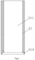
FIG. 2 is a structural diagram of the shaft body of the dummy shaft in the low-pressure aluminium casting mold for motor rotor of the present invention; -
FIG. 3 is a structural diagram of the dummy shaft lower cover and the diverter in the low-pressure cast aluminium mold for motor rotor of the present invention; -
FIG. 4 is a partial structural diagram of the lower backing plate in the low-pressure cast aluminium mold for motor rotor of the present invention. - In order to make the object, technical solution and advantages of the invention clearer, the technical solution of the invention will be described completely in combination with the embodiments of the invention and the corresponding drawings. Obviously, the described embodiments are only part of the embodiments of the invention, not all of them.
- As shown in
FIG. 1 to FIG. 4 , the low-pressure aluminium casting mold for motor rotor of the present invention includes an upper blade profile assembly, a lower blade profile assembly, a rotor core 1, adummy shaft 2 and adiverter 7. The upper blade profile assembly includes anupper backing plate 3 and anupper mold 4, and the lower blade profile assembly includes alower backing plate 5 and a lower mold 6. Thedummy shaft 2 includes a vertically arranged shaft body 2-1, a dummy shaft upper cover 2-2 arranged at the upper part of the shaft body 2-1, and a dummy shaft lower cover 2-3 arranged at the lower part of the shaft body 2-1. Thediverter 7 is arranged between thedummy shaft 2 and the lower mold 6. The low-pressure aluminium casting mold further includes a firstpressing device 8 and four sets of secondpressing devices 9, wherein the firstpressing device 8 is arranged at the top of thedummy shaft 2 to press the middle part of the rotor core 1, and the four sets of secondpressing devices 9 are arranged at four corner positions of the low-pressure aluminium casting mold. - The middle parts of the four corners of the
lower backing plate 5 are respectively provided with horizontal clamping slots 5-1 and U-shaped holes 5-2, the U-shaped hole 5-2 is provided on thelower backing plate 5 and above the clamping slot 5-1, the opening of the U-shaped hole 5-2 faces the outside, and the position of theupper backing plate 3 corresponding to the U-shaped hole 5-2 is provided with a hold-down through hole 3-1. - The second
pressing device 9 includes a pull rod 9-1, a clamping plate 9-2 and a hold-down nut 9-3, wherein the clamping plate 9-2 is arranged in the clamping slot 5-1; the pull rod 9-1 is vertically arranged, and the bottom end of the pull rod 9-1 passes through the U-shaped hole 5-2 and is connected with the top surface of the clamping plate 9-2; the outer wall of the upper section of the pull rod 9-1 is provided with external threads; the top end of the pull rod 9-1 passes through the corresponding hold-down through hole 3-1; and the hold-down nut 9-3 is connected with the external threads on the pull rod 9-1 by threads. - The area of the horizontal cross section of the clamping slot 5-1 is larger than that of the U-shaped hole 5-2, thereby limiting the clamping plate 9-2 to prevent the clamping plate 9-2 from falling off in the fastening process.
- The first
pressing device 8 includes a pressing cover 8-1 and an eyebolt 8-2. The pressing cover 8-1 is a cylindrical tube structure with an open bottom and is coaxially covered on the top of thedummy shaft 2, and the bottom edge of the pressing cover 8-1 is pressed on the top surface of the rotor core 1. The middle part of the dummy shaft upper cover 2-2 is provided with a first threaded hole 2-2-1, the top surface of the pressing cover 8-1 is provided with a second threaded hole 8-1-1, and the lower end of the eyebolt 8-2 passes through the second threaded hole 8-1-1 and is connected with the first threaded hole 2-2-1. The firstpressing device 8 presses the rotor core 1 with the pressing cover 8-1 by tightening the eyebolt 8-2. - The middle part of the shaft body 2-1 is vertically provided with a first through hole 2-1-1, the bottom end of the first through hole 2-1-1 is coaxially provided with an annular clamping slot 2-1-2, and the inner diameter of the annular clamping slot 2-1-2 is larger than that of the first through hole 2-1-1. The dummy shaft lower cover 2-3 includes a circular cover plate 2-3-1 and a cover body 2-3-2 arranged on the top surface of the circular cover plate 2-3-1, wherein the cover body 2-3-2 has a vertically arranged cylindrical structure, the upper part of the cover body 2-3-2 extends into the first through hole 2-1-1 and the bottom surface of the shaft body 2-1 is arranged on the top surface of the circular cover plate 2-3-1, the outer wall of the lower part of the cover body 2-3-2 is provided with an annular clamping table 2-3-3 matched with the annular clamping slot 2-1-2, the outer diameter of the circular cover plate 2-3-1 is larger than that of the shaft body 2-1, and the middle part of the dummy shaft lower cover 2-3 is vertically provided with a second through hole 2-3-4. The
diverter 7 has a cylindrical structure, the middle of the top surface of thediverter 7 is provided with a cover plate placing groove 7-1 matched with the circular cover plate 2-3-1, the center of the cover plate placing groove 7-1 is coaxially provided with a cylindrical protrusion 7-2 which extends into the second through hole 2-3-4 and the circular cover plate 2-3-1 is placed in the cover plate placing groove 7-1, and the center of the bottom surface of thediverter 7 is provided with an arc protrusion 7-3 which bulges downward. - Furthermore, two sets of lifting rings 3-2 are arranged on the top surface of the
upper backing plate 3 for the convenience of hoisting and transportation. - Furthermore, there is clearance fit between the cylindrical protrusion 7-2 and the second through hole 2-3-4, and between the cover plate placing groove 7-1 and the circular cover plate 2-3-1. The clearance fit between the
diverter 7 and the dummy shaft lower cover 2-3 facilitates both installation and disassembly. - Furthermore, chamfers are arranged at the outer edge of the bottom surface of the circular cover plate 2-3-1, the outer edge of the bottom surface of the
diverter 7, the bottom edge of the cover plate placing groove 7-1 and the bottom edge of the second through hole 2-3-4. - In the low-pressure aluminium casting mold for motor rotor of the present invention, the second
pressing device 9 has simple structure, convenient operation and low cost, and can fasten the rotor core 1 through the hold-down nut 9-3 in the hot lamination process. - In the low-pressure aluminium casting mold for motor rotor of the present invention, the arrangement of the clamping slot 5-1 and the U-shaped hole 52 saves space, and can realize compaction without adding external compaction equipment, so that the cost is low and the lower mold 6 will not be affected.
- In the low-pressure aluminium casting mold for motor rotor of the present invention, the arrangement of the circular arc protrusion 7-3 makes the distribution of molten aluminium more uniform, and improves the casting quality.
- The low-pressure aluminium casting process for motor rotor of the present invention comprises the following steps:
- 1) cold lamination: sequentially stacking a plurality of rotor laminations on the
dummy shaft 2 of the low-pressure aluminium casting mold, applying a lamination pressure to the pressing cover 8-1 of the firstpressing device 8 by an oil press, thereby laminating the plurality of rotor laminations to form a rotor core 1. The tonnage of the oil press is 30-50T and the lamination pressure exerted by the oil press is 2.5-3.0MPa. After the whole height of the rotor core 1 reaches a first specified length, the rotor core 1 is fastened to thedummy shaft 2 by the pressing cover 8-1 and eyebolt 8-2 of the firstpressing device 8; - 2) heating of the rotor core: transporting the rotor core 1 fastened to the
dummy shaft 2 by the firstpressing device 8 in step 1) to a heating furnace for heating. Firstly, the rotor core 1 is heated at a temperature rise rate of 70-90°C/h for 1 hour and then kept warm for 1 hour. Then, the rotor core 1 is heated at a temperature rise rate of 70-90°C/h for 1 hour and then kept warm for 1 hour. Finally, the rotor core 1 is heated at a temperature rise rate of 80-100°C/h for 1 hour and then kept warm for 5 hours; - 3) mold preparation: assembling the
lower backing plate 5 and the lower mold 6, placing thediverter 7 on the lower mold 6, installing the clamping plate 9-2 in the clamping slot 5-1 of thelower backing plate 5, and vertically setting the pull rod 9-1 in place; - 4) hot lamination: lifting the rotor core 1 heated in step 2) out of the heating furnace, placing the lower cover 2-3 of the
dummy shaft 2 on thediverter 7, placing theupper backing plate 3 and theupper mold 4 on the rotor core 1, passing the hold-down through hole 3-1 on theupper backing plate 3 through the upper end of the pull rod 9-1, preliminarily fastening the rotor core 1 by a hold-down nut 9-3, and starting the oil press to continuously laminate the rotor core 1 until the overall height of the rotor core 1 reaches a second specified length, and then tightening the hold-down nut 9-3 again; - 5) low-pressure casting: quickly lifting the whole mold fastened in step 4) to a low-pressure aluminium casting machine for aluminium casting, and completing the low-pressure aluminium casting of the motor rotor.
- Due to the thermal expansion of the rotor core after being heated, in order to eliminate the influence of thermal expansion during hot lamination, the second specified length of the rotor core 1 in hot lamination is selected as 1.013 times of the first specified length of the rotor core 1 in cold lamination, i.e., the second specified length of the rotor core in hot lamination = the first specified length of the rotor core in cold lamination ×1.013.
- Further, in the low-pressure casting step, the pressure parameters of low-pressure aluminium casting are controlled as follows:
- 5.1) liquid lifting stage: pressurizing the molten aluminium at a pressure rise rate of 4.6-5.0KPa/s for 10s from an initial pressure of 2KPa, thereby making the pressure reach 48-52KPa;
- 5.2) mold filling stage: pressurizing at a pressure rise rate of 7.3-7.7KPa/s for 4s, thereby making the pressure reach 77.2-82.8KPa;
- 5.3) pressure maintaining stage: maintaining the pressure at 77.2-82.8KPa for 405s;
- 5.4) pressure release stage: releasing the residual pressure after the pressure maintaining stage is completed.
- The low-pressure aluminium casting process for motor rotor of the present invention will be described in detail with reference to the following specific embodiments.
- The low-pressure aluminium casting process for motor rotor of Embodiment 1 includes the following steps:
- 1) cold lamination: sequentially stacking a plurality of rotor laminations on the
dummy shaft 2 of the low-pressure aluminium casting mold, applying a lamination pressure to the pressing cover 8-1 of the firstpressing device 8 by an oil press, thereby laminating the plurality of rotor laminations to form a rotor core 1. The tonnage of the oil press is 30T and the lamination pressure exerted by the oil press is 2.5MPa. After the whole height of the rotor core 1 reaches a first specified length, the rotor core 1 is fastened to thedummy shaft 2 by the pressing cover 8-1 and eyebolt 8-2 of the firstpressing device 8; - 2) heating of the rotor core: transporting the rotor core 1 fastened to the
dummy shaft 2 by the firstpressing device 8 in step 1) to a heating furnace for heating. Firstly, the rotor core 1 is heated at a temperature rise rate of 70°C/h for 1 hour and then kept warm for 1 hour. Then, the rotor core 1 is heated at a temperature rise rate of 70°C/h for 1 hour and then kept warm for 1 hour. Finally, the rotor core 1 is heated at a temperature rise rate of 80°C/h for 1 hour and then kept warm for 5 hours; - 3) mold preparation: assembling the
lower backing plate 5 and the lower mold 6, placing thediverter 7 on the lower mold 6, installing the clamping plate 9-2 in the clamping slot 5-1 of thelower backing plate 5, and vertically setting the pull rod 9-1 in place; - 4) hot lamination: lifting the rotor core 1 heated in step 2) out of the heating furnace, placing the lower cover 2-3 of the
dummy shaft 2 on thediverter 7, placing theupper backing plate 3 and theupper mold 4 on the rotor core 1, passing the hold-down through hole 3-1 on theupper backing plate 3 through the upper end of the pull rod 9-1, preliminarily fastening the rotor core 1 by a hold-down nut 9-3, and starting the oil press to continuously laminate the rotor core 1 until the overall height of the rotor core 1 reaches a second specified length, and then tightening the hold-down nut 9-3 again, wherein the second specified length of the rotor core 1 in hot lamination = the first specified length of the rotor core 1 in cold lamination ×1.013; - 5) low-pressure casting: quickly lifting the whole mold fastened in step 4) to a low-pressure aluminium casting machine for aluminium casting, and completing the low-pressure aluminium casting of the motor rotor.
- The low-pressure aluminium casting process for motor rotor of
Embodiment 2 includes the following steps: - 1) cold lamination: sequentially stacking a plurality of rotor laminations on the
dummy shaft 2 of the low-pressure aluminium casting mold, applying a lamination pressure to the pressing cover 8-1 of the firstpressing device 8 by an oil press, thereby laminating the plurality of rotor laminations to form a rotor core 1. The tonnage of the oil press is 40T and the lamination pressure exerted by the oil press is 2.8MPa. After the whole height of the rotor core 1 reaches a first specified length, the rotor core 1 is fastened to thedummy shaft 2 by the pressing cover 8-1 and eyebolt 8-2 of the firstpressing device 8; - 2) heating of the rotor core: transporting the rotor core 1 fastened to the
dummy shaft 2 by the firstpressing device 8 in step 1) to a heating furnace for heating. Firstly, the rotor core 1 is heated at a temperature rise rate of 80°C/h for 1 hour and then kept warm for 1 hour. Then, the rotor core 1 is heated at a temperature rise rate of 80°C/h for 1 hour and then kept warm for 1 hour. Finally, the rotor core 1 is heated at a temperature rise rate of 90°C/h for 1 hour and then kept warm for 5 hours; - 3) mold preparation: assembling the
lower backing plate 5 and the lower mold 6, placing thediverter 7 on the lower mold 6, installing the clamping plate 9-2 in the clamping slot 5-1 of thelower backing plate 5, and vertically setting the pull rod 9-1 in place; - 4) hot lamination: lifting the rotor core 1 heated in step 2) out of the heating furnace, placing the lower cover 2-3 of the
dummy shaft 2 on thediverter 7, placing theupper backing plate 3 and theupper mold 4 on the rotor core 1, passing the hold-down through hole 3-1 on theupper backing plate 3 through the upper end of the pull rod 9-1, preliminarily fastening the rotor core 1 by a hold-down nut 9-3, and starting the oil press to continuously laminate the rotor core 1 until the overall height of the rotor core 1 reaches a second specified length, and then tightening the hold-down nut 9-3 again, wherein the second specified length of the rotor core 1 in hot lamination = the first specified length of the rotor core 1 in cold lamination ×1.013; - 5) low-pressure casting: quickly lifting the whole mold fastened in step 4) to a low-pressure aluminium casting machine for aluminium casting, and completing the low-pressure aluminium casting of the motor rotor.
- The low-pressure aluminium casting process for motor rotor of
Embodiment 3 includes the following steps: - 1) cold lamination: sequentially stacking a plurality of rotor laminations on the
dummy shaft 2 of the low-pressure aluminium casting mold, applying a lamination pressure to the pressing cover 8-1 of the firstpressing device 8 by an oil press, thereby laminating the plurality of rotor laminations to form a rotor core 1. The tonnage of the oil press is 50T and the lamination pressure exerted by the oil press is 3.0MPa. After the whole height of the rotor core 1 reaches a first specified length, the rotor core 1 is fastened to thedummy shaft 2 by the pressing cover 8-1 and eyebolt 8-2 of the firstpressing device 8; - 2) heating of the rotor core: transporting the rotor core 1 fastened to the
dummy shaft 2 by the firstpressing device 8 in step 1) to a heating furnace for heating. Firstly, the rotor core 1 is heated at a temperature rise rate of 90°C/h for 1 hour and then kept warm for 1 hour. Then, the rotor core 1 is heated at a temperature rise rate of 90°C/h for 1 hour and then kept warm for 1 hour. Finally, the rotor core 1 is heated at a temperature rise rate of 100°C/h for 1 hour and then kept warm for 5 hours; - 3) mold preparation: assembling the
lower backing plate 5 and the lower mold 6, placing thediverter 7 on the lower mold 6, installing the clamping plate 9-2 in the clamping slot 5-1 of thelower backing plate 5, and vertically setting the pull rod 9-1 in place; - 4) hot lamination: lifting the rotor core 1 heated in step 2) out of the heating furnace, placing the lower cover 2-3 of the
dummy shaft 2 on thediverter 7, placing theupper backing plate 3 and theupper mold 4 on the rotor core 1, passing the hold-down through hole 3-1 on theupper backing plate 3 through the upper end of the pull rod 9-1, preliminarily fastening the rotor core 1 by a hold-down nut 9-3, and starting the oil press to continuously laminate the rotor core 1 until the overall height of the rotor core 1 reaches a second specified length, and then tightening the hold-down nut 9-3 again, wherein the second specified length of the rotor core 1 in hot lamination = the first specified length of the rotor core 1 in cold lamination ×1.013; - 5) low-pressure casting: quickly lifting the whole mold fastened in step 4) to a low-pressure aluminium casting machine for aluminium casting, and completing the low-pressure aluminium casting of the motor rotor.
- To sum up, compared with the prior art, the low-pressure aluminium casting mold for motor rotor and the low-pressure aluminium casting process for motor rotor have the following advantages and beneficial effects.
- In the low-pressure aluminium casting mold for motor rotor, the compression of the first pressing device and the second pressing device ensures the lamination compactness of the rotor core, thoroughly eliminates the hidden danger of aluminium leakage in the aluminium casting process of the rotor, improves the success rate of aluminium casting of the motor rotor, ensures the quality of the cast-aluminium rotor, and has the advantages of simple process and low cost. The second pressing device fastens the upper backing plate and the lower backing plate through the pull rod, which realizes the pressing of the upper and lower molds and the rotor core. It has simple structure and there is no need to add complicated pressing equipment for compression. The operation and adjustment are convenient and the operation efficiency is also improved. The downward-bulged arc protrusion arranged at the center of the bottom surface of the diverter makes the distribution of molten aluminium more uniform and thus improves the casting quality.
- In the low-pressure aluminium casting process for motor rotor, through the cold lamination and hot lamination together with the double compression of the first pressing device and the second pressing device, the lamination compactness of the rotor core is ensured, the hidden danger of aluminium leakage in the aluminium casting process of the rotor is completely eliminated, the success rate of aluminium casting of motor rotor is improved, and the quality of the cast-aluminium rotor is guaranteed. Moreover, it has the advantages of simple process and low cost. The upper backing plate and the lower backing plate can be fastened to each other through the pull rod of the second pressing device, thus realizing the pressing of the upper and lower molds and the rotor core. There is no need to add complicated pressing equipment for pressing. Besides, the operation and adjustment are convenient and the operation efficiency is also improved.
- It should be noted that in the context of this invention, the terms such as "first" and "second" are only used to distinguish one component or operation from another, and do not necessarily require or imply any such actual relationship or order between these components or operations. Moreover, the terms "include", "comprise" or any other variation thereof are intended to cover non-exclusive inclusion, so that a process, method, article or device including a series of elements includes not only those elements, but also other elements not explicitly listed, or elements inherent in such process, method, article or device. In addition, unless otherwise specified, "front", "back", "left", "right", "up", "down", "inside" and "outside" in the context of this invention are all referred to the placement state shown in the figures.
- It is to be understood that the foregoing description relates to exemplary embodiments of the present invention and that modifications may be made without departing from the spirit and scope of the present invention as set forth in the claims.
Claims (3)
- A low-pressure aluminium casting process for motor rotor, implemented using a low-pressure aluminium casting mold for motor rotor, the low-pressure aluminium casting mold for motor rotor includes an upper backing plate (3) and an upper mold (4), a lower backing plate (5) and a lower mold (6), a rotor core (1), a dummy shaft (2), a diverter (7), a first pressing device (8) and four sets of second pressing devices (9), wherein the dummy shaft (2) includes a vertically arranged shaft body (2-1), a dummy shaft upper cover (2-2) arranged at the upper part of the shaft body (2-1), and a dummy shaft lower cover (2-3) arranged at the lower part of the shaft body (2-1), the diverter (7) is arranged between the dummy shaft (2) and the lower mold (6); the first pressing device (8) is arranged at the top of the dummy shaft (2) to press the middle part of the rotor core (1), and the four sets of second pressing devices (9) are arranged at four corner positions of the low-pressure aluminium casting mold; the middle parts of the four corners of the lower backing plate (5) are respectively provided with horizontal clamping slots (5-1) and U-shaped holes (5-2), the U-shaped hole (5-2) is provided on the lower backing plate (5) and above the clamping slot (5-1), the opening of the U-shaped hole (5-2) faces the outside, and the position of the upper backing plate (3) corresponding to the U-shaped hole (5-2) is provided with a hold-down through hole (3-1); the second pressing device (9) includes a pull rod (9-1), a clamping plate (9-2) and a hold-down nut (9-3), the clamping plate (9-2) is arranged in the clamping slot (5-1), the pull rod (9-1) is vertically arranged with its bottom end passing through the U-shaped hole (5-2) and connecting with the top surface of the clamping plate (9-2), the outer wall of the upper section of the pull rod (9-1) is provided with external threads, the top end of the pull rod (9-1) passes through the corresponding hold-down through hole (3-1), and the hold-down nut (9-3) is connected with the external threads on the pull rod (9-1) by threads; the first pressing device (8) includes a pressing cover (8-1) and an eyebolt (8-2), the pressing cover (8-1) is a cylindrical tube structure with an open bottom and is coaxially covered on the top of the dummy shaft (2), and the bottom edge of the pressing cover (8-1) is pressed on the top surface of the rotor core (1); the middle part of the dummy shaft upper cover (2-2) is provided with a first threaded hole (2-2-1), the top surface of the pressing cover (8-1) is provided with a second threaded hole (8-1-1), and the lower end of the eyebolt (8-2) passes through the second threaded hole (8-1-1) and is connected with the first threaded hole (2-2-1),
characterized in that the low-pressure aluminium casting process for motor rotor includes the following steps:1) cold lamination: sequentially stacking a plurality of rotor laminations on the dummy shaft (2) of the low-pressure aluminium casting mold, applying a lamination pressure to the pressing cover (8-1) of the first pressing device (8) by an oil press, thereby laminating the plurality of rotor laminations to form a rotor core (1), wherein the tonnage of the oil press is 30-50T and the lamination pressure exerted by the oil press is 2.5-3.0MPa; after the whole height of the rotor core (1) reaches a first specified length, the rotor core (1) is fastened to the dummy shaft (2) by the pressing cover (8-1) and eyebolt (8-2) of the first pressing device (8);2) heating of the rotor core: transporting the rotor core (1) fastened to the dummy shaft (2) by the first pressing device (8) in step 1) to a heating furnace for heating, wherein, firstly the rotor core (1) is heated at a temperature rise rate of 70-90°C/h for 1 hour and then kept warm for 1 hour, then the rotor core (1) is heated at a temperature rise rate of 70-90°C/h for 1 hour and then kept warm for 1 hour, finally the rotor core (1) is heated at a temperature rise rate of 80-100°C/h for 1 hour and then kept warm for 5 hours;3) mold preparation: assembling the lower backing plate (5) and the lower mold (6), placing the diverter (7) on the lower mold (6), installing the clamping plate (9-2) in the clamping slot (5-1) of the lower backing plate (5), and vertically setting the pull rod (9-1) in place;4) hot lamination: lifting the rotor core (1) heated in step 2) out of the heating furnace, placing the lower cover (2-3) of the dummy shaft (2) on the diverter (7), placing the upper backing plate (3) and the upper mold (4) on the rotor core (1), passing the hold-down through hole (3-1) on the upper backing plate (3) through the upper end of the pull rod (9-1), preliminarily fastening the rotor core (1) by a hold-down nut (9-3), and starting the oil press to continuously laminate the rotor core (1) until the overall height of the rotor core (1) reaches a second specified length, and then tightening the hold-down nut (9-3) again;5) low-pressure casting: quickly lifting the whole mold fastened in step 4) to a low-pressure aluminium casting machine for aluminium casting, and completing the low-pressure aluminium casting of the motor rotor. - The low-pressure aluminium casting process for motor rotor according to claim 1, characterized in that the second specified length of the rotor core in hot lamination is 1.013 times of the first specified length of the rotor core in cold lamination.
- The low-pressure aluminium casting process for motor rotor according to claim 1, characterized in that, in the low-pressure casting step the pressure parameters of low-pressure aluminium casting are controlled as follows:5.1) liquid lifting stage: pressurizing the molten aluminium at a pressure rise rate of 4.6-5.0KPa/s for 10s from an initial pressure of 2KPa, thereby making the pressure reach 48-52KPa;5.2) mold filling stage: pressurizing at a pressure rise rate of 7.3-7.7KPa/s for 4s, thereby making the pressure reach 77.2-82.8KPa;5.3) pressure maintaining stage: maintaining the pressure at 77.2-82.8KPa for 405s;5.4) pressure release stage: releasing the residual pressure after the pressure maintaining stage is completed.
Applications Claiming Priority (3)
| Application Number | Priority Date | Filing Date | Title |
|---|---|---|---|
| CN202121610699.5U CN215279820U (en) | 2021-07-15 | 2021-07-15 | A low-pressure cast aluminum mold for cast aluminum rotor with special end plate structure |
| CN202110802448.5A CN113319265B (en) | 2021-07-15 | 2021-07-15 | Low-pressure aluminum casting process and mold for cast aluminum rotor with special end plate structure |
| PCT/CN2022/103843 WO2023284587A1 (en) | 2021-07-15 | 2022-07-05 | Low-pressure aluminum casting mold and low-pressure aluminum casting process for motor rotor |
Publications (3)
| Publication Number | Publication Date |
|---|---|
| EP4209290A1 EP4209290A1 (en) | 2023-07-12 |
| EP4209290A4 EP4209290A4 (en) | 2024-01-31 |
| EP4209290B1 true EP4209290B1 (en) | 2025-03-19 |
Family
ID=84919011
Family Applications (1)
| Application Number | Title | Priority Date | Filing Date |
|---|---|---|---|
| EP22841224.3A Active EP4209290B1 (en) | 2021-07-15 | 2022-07-05 | Low-pressure aluminum casting mold and low-pressure aluminum casting process for motor rotor |
Country Status (4)
| Country | Link |
|---|---|
| US (1) | US12226818B2 (en) |
| EP (1) | EP4209290B1 (en) |
| ES (1) | ES3031163T3 (en) |
| WO (1) | WO2023284587A1 (en) |
Families Citing this family (1)
| Publication number | Priority date | Publication date | Assignee | Title |
|---|---|---|---|---|
| CN116275006A (en) * | 2023-02-22 | 2023-06-23 | 上海电机系统节能工程技术研究中心有限公司 | Motor rotor casting aluminum device and aluminum casting method thereof |
Family Cites Families (13)
| Publication number | Priority date | Publication date | Assignee | Title |
|---|---|---|---|---|
| US2996773A (en) * | 1957-09-03 | 1961-08-22 | Gen Electric | Method of casting squirrel cage rotors |
| US3349478A (en) * | 1965-05-19 | 1967-10-31 | Gen Electric | Method of manufacturing a rotor assembly |
| US20030062786A1 (en) * | 2001-10-03 | 2003-04-03 | Reiter Frederick B. | Manufacturing method and composite powder metal rotor assembly for induction machine |
| US6848495B2 (en) * | 2003-05-19 | 2005-02-01 | Bristol Compressors, Inc. | Method of manufacturing a laminated rotor |
| US20100171387A1 (en) * | 2009-01-07 | 2010-07-08 | Bae Systems Controls Inc. | Die Cast Rotor With Steel End Rings to Contain Aluminum |
| DE102014210339A1 (en) * | 2014-06-02 | 2015-12-03 | Siemens Aktiengesellschaft | Squirrel cage of an asynchronous machine |
| CN204545381U (en) * | 2015-01-22 | 2015-08-12 | 山西天海泵业有限公司 | Diving generator rotor cage bar Casting Equipment |
| CN105921719A (en) * | 2016-06-28 | 2016-09-07 | 重庆迎瑞升压铸有限公司 | Motor rotor cast aluminum mold with guide mechanism |
| CN109986056B (en) * | 2018-01-11 | 2020-11-06 | 山西电机制造有限公司 | Low-pressure aluminum casting process method for cast aluminum rotor |
| CN109274226A (en) * | 2018-07-31 | 2019-01-25 | 西安泰富西玛电机有限公司 | A kind of winding-type, copper bar rotor rotor cold pressing hot jacket |
| CN212371156U (en) * | 2020-05-20 | 2021-01-19 | 山西电机制造有限公司 | High-voltage motor cast aluminum rotor die based on low-pressure cast aluminum |
| CN111496225B (en) * | 2020-05-22 | 2021-10-15 | 山西电机制造有限公司 | Low-pressure cast aluminum pressurization process for cast aluminum rotor of three-phase asynchronous high-voltage motor |
| CN113319265B (en) * | 2021-07-15 | 2025-05-23 | 山西电机制造有限公司 | Low-pressure aluminum casting process and mold for cast aluminum rotor with special end plate structure |
-
2022
- 2022-07-05 ES ES22841224T patent/ES3031163T3/en active Active
- 2022-07-05 US US18/561,188 patent/US12226818B2/en active Active
- 2022-07-05 EP EP22841224.3A patent/EP4209290B1/en active Active
- 2022-07-05 WO PCT/CN2022/103843 patent/WO2023284587A1/en not_active Ceased
Also Published As
| Publication number | Publication date |
|---|---|
| EP4209290A4 (en) | 2024-01-31 |
| ES3031163T3 (en) | 2025-07-04 |
| US12226818B2 (en) | 2025-02-18 |
| US20240253110A1 (en) | 2024-08-01 |
| WO2023284587A1 (en) | 2023-01-19 |
| EP4209290A1 (en) | 2023-07-12 |
Similar Documents
| Publication | Publication Date | Title |
|---|---|---|
| CN102170201B (en) | Method of resin sealing permanent magnets in laminated rotor core | |
| CN113319265B (en) | Low-pressure aluminum casting process and mold for cast aluminum rotor with special end plate structure | |
| EP3825035A1 (en) | Method for casting aluminum in rotor | |
| EP4209290A1 (en) | Low-pressure aluminum casting mold and low-pressure aluminum casting process for motor rotor | |
| CN103084577B (en) | Device and method for step type hot extrusion preparation of Nd-phase-rich Nd2Fe14B/alpha-Fe permanent magnet | |
| CN103343266B (en) | High thermal conductivity graphite high silicon aluminum matrix composite material and its preparation process | |
| KR20120010416A (en) | Centrifugal casting apparatus for manufacturing copper cage rotor and centrifugal casting method | |
| CN114247865A (en) | Device and method for vertically casting a rotor for an asynchronous machine | |
| CN111496225B (en) | Low-pressure cast aluminum pressurization process for cast aluminum rotor of three-phase asynchronous high-voltage motor | |
| CN215279820U (en) | A low-pressure cast aluminum mold for cast aluminum rotor with special end plate structure | |
| JP2622875B2 (en) | Manufacturing method of metal parts | |
| JP4245988B2 (en) | Manufacturing apparatus and manufacturing method for cage rotor | |
| CN114769549A (en) | Motor rotor slow-pushing booster-type casting process | |
| CN116031059A (en) | A dry variable coil forming mold and a dry variable coil forming process | |
| CN115664135A (en) | Die casting process of rotor core | |
| CN214185197U (en) | Die locking device for die casting mold | |
| CN223849560U (en) | A casting device for anti-slide piles for geological disaster control | |
| CN222153425U (en) | Hot-pressing shaping die for new energy charging pile liquid-cooled castings | |
| CN114289702B (en) | A preparation device and preparation method of bimetallic composite material | |
| CN223834912U (en) | Insulating film hot pressing die | |
| CN214505252U (en) | Terminal board die for pouring dry type transformer coil | |
| US20250300530A1 (en) | Device and method for manufacturing rotor for induction motor | |
| CN218940896U (en) | Stacked tool of keyless silicon steel sheets | |
| JPH03159546A (en) | Manufacture of cage rotor | |
| CN210254169U (en) | Rotating plate die |
Legal Events
| Date | Code | Title | Description |
|---|---|---|---|
| STAA | Information on the status of an ep patent application or granted ep patent |
Free format text: STATUS: THE INTERNATIONAL PUBLICATION HAS BEEN MADE |
|
| PUAI | Public reference made under article 153(3) epc to a published international application that has entered the european phase |
Free format text: ORIGINAL CODE: 0009012 |
|
| STAA | Information on the status of an ep patent application or granted ep patent |
Free format text: STATUS: REQUEST FOR EXAMINATION WAS MADE |
|
| 17P | Request for examination filed |
Effective date: 20230403 |
|
| AK | Designated contracting states |
Kind code of ref document: A1 Designated state(s): AL AT BE BG CH CY CZ DE DK EE ES FI FR GB GR HR HU IE IS IT LI LT LU LV MC MK MT NL NO PL PT RO RS SE SI SK SM TR |
|
| A4 | Supplementary search report drawn up and despatched |
Effective date: 20240105 |
|
| RIC1 | Information provided on ipc code assigned before grant |
Ipc: B21D 28/22 20060101ALI20231222BHEP Ipc: B22D 33/04 20060101ALI20231222BHEP Ipc: B22D 19/00 20060101ALI20231222BHEP Ipc: B22D 18/04 20060101AFI20231222BHEP |
|
| DAV | Request for validation of the european patent (deleted) | ||
| DAX | Request for extension of the european patent (deleted) | ||
| GRAP | Despatch of communication of intention to grant a patent |
Free format text: ORIGINAL CODE: EPIDOSNIGR1 |
|
| STAA | Information on the status of an ep patent application or granted ep patent |
Free format text: STATUS: GRANT OF PATENT IS INTENDED |
|
| INTG | Intention to grant announced |
Effective date: 20241120 |
|
| GRAS | Grant fee paid |
Free format text: ORIGINAL CODE: EPIDOSNIGR3 |
|
| GRAA | (expected) grant |
Free format text: ORIGINAL CODE: 0009210 |
|
| STAA | Information on the status of an ep patent application or granted ep patent |
Free format text: STATUS: THE PATENT HAS BEEN GRANTED |
|
| AK | Designated contracting states |
Kind code of ref document: B1 Designated state(s): AL AT BE BG CH CY CZ DE DK EE ES FI FR GB GR HR HU IE IS IT LI LT LU LV MC MK MT NL NO PL PT RO RS SE SI SK SM TR |
|
| REG | Reference to a national code |
Ref country code: GB Ref legal event code: FG4D |
|
| REG | Reference to a national code |
Ref country code: CH Ref legal event code: EP |
|
| REG | Reference to a national code |
Ref country code: IE Ref legal event code: FG4D |
|
| REG | Reference to a national code |
Ref country code: DE Ref legal event code: R096 Ref document number: 602022012071 Country of ref document: DE |
|
| REG | Reference to a national code |
Ref country code: ES Ref legal event code: FG2A Ref document number: 3031163 Country of ref document: ES Kind code of ref document: T3 Effective date: 20250704 |
|
| PG25 | Lapsed in a contracting state [announced via postgrant information from national office to epo] |
Ref country code: RS Free format text: LAPSE BECAUSE OF FAILURE TO SUBMIT A TRANSLATION OF THE DESCRIPTION OR TO PAY THE FEE WITHIN THE PRESCRIBED TIME-LIMIT Effective date: 20250619 |
|
| PG25 | Lapsed in a contracting state [announced via postgrant information from national office to epo] |
Ref country code: FI Free format text: LAPSE BECAUSE OF FAILURE TO SUBMIT A TRANSLATION OF THE DESCRIPTION OR TO PAY THE FEE WITHIN THE PRESCRIBED TIME-LIMIT Effective date: 20250319 |
|
| REG | Reference to a national code |
Ref country code: LT Ref legal event code: MG9D |
|
| PG25 | Lapsed in a contracting state [announced via postgrant information from national office to epo] |
Ref country code: NO Free format text: LAPSE BECAUSE OF FAILURE TO SUBMIT A TRANSLATION OF THE DESCRIPTION OR TO PAY THE FEE WITHIN THE PRESCRIBED TIME-LIMIT Effective date: 20250619 |
|
| PG25 | Lapsed in a contracting state [announced via postgrant information from national office to epo] |
Ref country code: HR Free format text: LAPSE BECAUSE OF FAILURE TO SUBMIT A TRANSLATION OF THE DESCRIPTION OR TO PAY THE FEE WITHIN THE PRESCRIBED TIME-LIMIT Effective date: 20250319 |
|
| PG25 | Lapsed in a contracting state [announced via postgrant information from national office to epo] |
Ref country code: LV Free format text: LAPSE BECAUSE OF FAILURE TO SUBMIT A TRANSLATION OF THE DESCRIPTION OR TO PAY THE FEE WITHIN THE PRESCRIBED TIME-LIMIT Effective date: 20250319 |
|
| PG25 | Lapsed in a contracting state [announced via postgrant information from national office to epo] |
Ref country code: GR Free format text: LAPSE BECAUSE OF FAILURE TO SUBMIT A TRANSLATION OF THE DESCRIPTION OR TO PAY THE FEE WITHIN THE PRESCRIBED TIME-LIMIT Effective date: 20250620 Ref country code: BG Free format text: LAPSE BECAUSE OF FAILURE TO SUBMIT A TRANSLATION OF THE DESCRIPTION OR TO PAY THE FEE WITHIN THE PRESCRIBED TIME-LIMIT Effective date: 20250319 |
|
| REG | Reference to a national code |
Ref country code: AT Ref legal event code: MK05 Ref document number: 1776566 Country of ref document: AT Kind code of ref document: T Effective date: 20250319 |
|
| PG25 | Lapsed in a contracting state [announced via postgrant information from national office to epo] |
Ref country code: NL Free format text: LAPSE BECAUSE OF FAILURE TO SUBMIT A TRANSLATION OF THE DESCRIPTION OR TO PAY THE FEE WITHIN THE PRESCRIBED TIME-LIMIT Effective date: 20250319 |
|
| PG25 | Lapsed in a contracting state [announced via postgrant information from national office to epo] |
Ref country code: SE Free format text: LAPSE BECAUSE OF FAILURE TO SUBMIT A TRANSLATION OF THE DESCRIPTION OR TO PAY THE FEE WITHIN THE PRESCRIBED TIME-LIMIT Effective date: 20250319 |
|
| PG25 | Lapsed in a contracting state [announced via postgrant information from national office to epo] |
Ref country code: SM Free format text: LAPSE BECAUSE OF FAILURE TO SUBMIT A TRANSLATION OF THE DESCRIPTION OR TO PAY THE FEE WITHIN THE PRESCRIBED TIME-LIMIT Effective date: 20250319 |
|
| PG25 | Lapsed in a contracting state [announced via postgrant information from national office to epo] |
Ref country code: PT Free format text: LAPSE BECAUSE OF FAILURE TO SUBMIT A TRANSLATION OF THE DESCRIPTION OR TO PAY THE FEE WITHIN THE PRESCRIBED TIME-LIMIT Effective date: 20250721 |
|
| PGFP | Annual fee paid to national office [announced via postgrant information from national office to epo] |
Ref country code: ES Payment date: 20250827 Year of fee payment: 4 |
|
| PGFP | Annual fee paid to national office [announced via postgrant information from national office to epo] |
Ref country code: DE Payment date: 20250828 Year of fee payment: 4 |
|
| PG25 | Lapsed in a contracting state [announced via postgrant information from national office to epo] |
Ref country code: IT Free format text: LAPSE BECAUSE OF FAILURE TO SUBMIT A TRANSLATION OF THE DESCRIPTION OR TO PAY THE FEE WITHIN THE PRESCRIBED TIME-LIMIT Effective date: 20250319 Ref country code: PL Free format text: LAPSE BECAUSE OF FAILURE TO SUBMIT A TRANSLATION OF THE DESCRIPTION OR TO PAY THE FEE WITHIN THE PRESCRIBED TIME-LIMIT Effective date: 20250319 |
|
| PGFP | Annual fee paid to national office [announced via postgrant information from national office to epo] |
Ref country code: BE Payment date: 20250721 Year of fee payment: 4 |
|
| PG25 | Lapsed in a contracting state [announced via postgrant information from national office to epo] |
Ref country code: AT Free format text: LAPSE BECAUSE OF FAILURE TO SUBMIT A TRANSLATION OF THE DESCRIPTION OR TO PAY THE FEE WITHIN THE PRESCRIBED TIME-LIMIT Effective date: 20250319 |
|
| PG25 | Lapsed in a contracting state [announced via postgrant information from national office to epo] |
Ref country code: CZ Free format text: LAPSE BECAUSE OF FAILURE TO SUBMIT A TRANSLATION OF THE DESCRIPTION OR TO PAY THE FEE WITHIN THE PRESCRIBED TIME-LIMIT Effective date: 20250319 Ref country code: EE Free format text: LAPSE BECAUSE OF FAILURE TO SUBMIT A TRANSLATION OF THE DESCRIPTION OR TO PAY THE FEE WITHIN THE PRESCRIBED TIME-LIMIT Effective date: 20250319 |
|
| PG25 | Lapsed in a contracting state [announced via postgrant information from national office to epo] |
Ref country code: RO Free format text: LAPSE BECAUSE OF FAILURE TO SUBMIT A TRANSLATION OF THE DESCRIPTION OR TO PAY THE FEE WITHIN THE PRESCRIBED TIME-LIMIT Effective date: 20250319 |
|
| PG25 | Lapsed in a contracting state [announced via postgrant information from national office to epo] |
Ref country code: SK Free format text: LAPSE BECAUSE OF FAILURE TO SUBMIT A TRANSLATION OF THE DESCRIPTION OR TO PAY THE FEE WITHIN THE PRESCRIBED TIME-LIMIT Effective date: 20250319 |
|
| PG25 | Lapsed in a contracting state [announced via postgrant information from national office to epo] |
Ref country code: IS Free format text: LAPSE BECAUSE OF FAILURE TO SUBMIT A TRANSLATION OF THE DESCRIPTION OR TO PAY THE FEE WITHIN THE PRESCRIBED TIME-LIMIT Effective date: 20250719 |
|
| REG | Reference to a national code |
Ref country code: DE Ref legal event code: R097 Ref document number: 602022012071 Country of ref document: DE |
|
| PG25 | Lapsed in a contracting state [announced via postgrant information from national office to epo] |
Ref country code: DK Free format text: LAPSE BECAUSE OF FAILURE TO SUBMIT A TRANSLATION OF THE DESCRIPTION OR TO PAY THE FEE WITHIN THE PRESCRIBED TIME-LIMIT Effective date: 20250319 |
|
| PLBE | No opposition filed within time limit |
Free format text: ORIGINAL CODE: 0009261 |
|
| STAA | Information on the status of an ep patent application or granted ep patent |
Free format text: STATUS: NO OPPOSITION FILED WITHIN TIME LIMIT |
|
| REG | Reference to a national code |
Ref country code: CH Ref legal event code: L10 Free format text: ST27 STATUS EVENT CODE: U-0-0-L10-L00 (AS PROVIDED BY THE NATIONAL OFFICE) Effective date: 20260128 |
|
| REG | Reference to a national code |
Ref country code: CH Ref legal event code: H13 Free format text: ST27 STATUS EVENT CODE: U-0-0-H10-H13 (AS PROVIDED BY THE NATIONAL OFFICE) Effective date: 20260224 |
|
| 26N | No opposition filed |
Effective date: 20251222 |
|
| PG25 | Lapsed in a contracting state [announced via postgrant information from national office to epo] |
Ref country code: LU Free format text: LAPSE BECAUSE OF NON-PAYMENT OF DUE FEES Effective date: 20250705 |
|
| PG25 | Lapsed in a contracting state [announced via postgrant information from national office to epo] |
Ref country code: FR Free format text: LAPSE BECAUSE OF NON-PAYMENT OF DUE FEES Effective date: 20250731 |
|
| PG25 | Lapsed in a contracting state [announced via postgrant information from national office to epo] |
Ref country code: CH Free format text: LAPSE BECAUSE OF NON-PAYMENT OF DUE FEES Effective date: 20250731 |