EP4209198A1 - Compact prosthetic heart valve device - Google Patents
Compact prosthetic heart valve device Download PDFInfo
- Publication number
- EP4209198A1 EP4209198A1 EP22214670.6A EP22214670A EP4209198A1 EP 4209198 A1 EP4209198 A1 EP 4209198A1 EP 22214670 A EP22214670 A EP 22214670A EP 4209198 A1 EP4209198 A1 EP 4209198A1
- Authority
- EP
- European Patent Office
- Prior art keywords
- valve
- heart valve
- heart
- valve prosthesis
- outer diameter
- Prior art date
- Legal status (The legal status is an assumption and is not a legal conclusion. Google has not performed a legal analysis and makes no representation as to the accuracy of the status listed.)
- Granted
Links
Images





Classifications
-
- A—HUMAN NECESSITIES
- A61—MEDICAL OR VETERINARY SCIENCE; HYGIENE
- A61F—FILTERS IMPLANTABLE INTO BLOOD VESSELS; PROSTHESES; DEVICES PROVIDING PATENCY TO, OR PREVENTING COLLAPSING OF, TUBULAR STRUCTURES OF THE BODY, e.g. STENTS; ORTHOPAEDIC, NURSING OR CONTRACEPTIVE DEVICES; FOMENTATION; TREATMENT OR PROTECTION OF EYES OR EARS; BANDAGES, DRESSINGS OR ABSORBENT PADS; FIRST-AID KITS
- A61F2/00—Filters implantable into blood vessels; Prostheses, i.e. artificial substitutes or replacements for parts of the body; Appliances for connecting them with the body; Devices providing patency to, or preventing collapsing of, tubular structures of the body, e.g. stents
- A61F2/02—Prostheses implantable into the body
- A61F2/24—Heart valves ; Vascular valves, e.g. venous valves; Heart implants, e.g. passive devices for improving the function of the native valve or the heart muscle; Transmyocardial revascularisation [TMR] devices; Valves implantable in the body
- A61F2/2412—Heart valves ; Vascular valves, e.g. venous valves; Heart implants, e.g. passive devices for improving the function of the native valve or the heart muscle; Transmyocardial revascularisation [TMR] devices; Valves implantable in the body with soft flexible valve members, e.g. tissue valves shaped like natural valves
- A61F2/2418—Scaffolds therefor, e.g. support stents
-
- A—HUMAN NECESSITIES
- A61—MEDICAL OR VETERINARY SCIENCE; HYGIENE
- A61F—FILTERS IMPLANTABLE INTO BLOOD VESSELS; PROSTHESES; DEVICES PROVIDING PATENCY TO, OR PREVENTING COLLAPSING OF, TUBULAR STRUCTURES OF THE BODY, e.g. STENTS; ORTHOPAEDIC, NURSING OR CONTRACEPTIVE DEVICES; FOMENTATION; TREATMENT OR PROTECTION OF EYES OR EARS; BANDAGES, DRESSINGS OR ABSORBENT PADS; FIRST-AID KITS
- A61F2/00—Filters implantable into blood vessels; Prostheses, i.e. artificial substitutes or replacements for parts of the body; Appliances for connecting them with the body; Devices providing patency to, or preventing collapsing of, tubular structures of the body, e.g. stents
- A61F2/02—Prostheses implantable into the body
- A61F2/24—Heart valves ; Vascular valves, e.g. venous valves; Heart implants, e.g. passive devices for improving the function of the native valve or the heart muscle; Transmyocardial revascularisation [TMR] devices; Valves implantable in the body
-
- A—HUMAN NECESSITIES
- A61—MEDICAL OR VETERINARY SCIENCE; HYGIENE
- A61F—FILTERS IMPLANTABLE INTO BLOOD VESSELS; PROSTHESES; DEVICES PROVIDING PATENCY TO, OR PREVENTING COLLAPSING OF, TUBULAR STRUCTURES OF THE BODY, e.g. STENTS; ORTHOPAEDIC, NURSING OR CONTRACEPTIVE DEVICES; FOMENTATION; TREATMENT OR PROTECTION OF EYES OR EARS; BANDAGES, DRESSINGS OR ABSORBENT PADS; FIRST-AID KITS
- A61F2/00—Filters implantable into blood vessels; Prostheses, i.e. artificial substitutes or replacements for parts of the body; Appliances for connecting them with the body; Devices providing patency to, or preventing collapsing of, tubular structures of the body, e.g. stents
- A61F2/02—Prostheses implantable into the body
- A61F2/24—Heart valves ; Vascular valves, e.g. venous valves; Heart implants, e.g. passive devices for improving the function of the native valve or the heart muscle; Transmyocardial revascularisation [TMR] devices; Valves implantable in the body
- A61F2/2409—Support rings therefor, e.g. for connecting valves to tissue
-
- A—HUMAN NECESSITIES
- A61—MEDICAL OR VETERINARY SCIENCE; HYGIENE
- A61F—FILTERS IMPLANTABLE INTO BLOOD VESSELS; PROSTHESES; DEVICES PROVIDING PATENCY TO, OR PREVENTING COLLAPSING OF, TUBULAR STRUCTURES OF THE BODY, e.g. STENTS; ORTHOPAEDIC, NURSING OR CONTRACEPTIVE DEVICES; FOMENTATION; TREATMENT OR PROTECTION OF EYES OR EARS; BANDAGES, DRESSINGS OR ABSORBENT PADS; FIRST-AID KITS
- A61F2/00—Filters implantable into blood vessels; Prostheses, i.e. artificial substitutes or replacements for parts of the body; Appliances for connecting them with the body; Devices providing patency to, or preventing collapsing of, tubular structures of the body, e.g. stents
- A61F2/02—Prostheses implantable into the body
- A61F2/24—Heart valves ; Vascular valves, e.g. venous valves; Heart implants, e.g. passive devices for improving the function of the native valve or the heart muscle; Transmyocardial revascularisation [TMR] devices; Valves implantable in the body
- A61F2/2412—Heart valves ; Vascular valves, e.g. venous valves; Heart implants, e.g. passive devices for improving the function of the native valve or the heart muscle; Transmyocardial revascularisation [TMR] devices; Valves implantable in the body with soft flexible valve members, e.g. tissue valves shaped like natural valves
-
- A—HUMAN NECESSITIES
- A61—MEDICAL OR VETERINARY SCIENCE; HYGIENE
- A61F—FILTERS IMPLANTABLE INTO BLOOD VESSELS; PROSTHESES; DEVICES PROVIDING PATENCY TO, OR PREVENTING COLLAPSING OF, TUBULAR STRUCTURES OF THE BODY, e.g. STENTS; ORTHOPAEDIC, NURSING OR CONTRACEPTIVE DEVICES; FOMENTATION; TREATMENT OR PROTECTION OF EYES OR EARS; BANDAGES, DRESSINGS OR ABSORBENT PADS; FIRST-AID KITS
- A61F2/00—Filters implantable into blood vessels; Prostheses, i.e. artificial substitutes or replacements for parts of the body; Appliances for connecting them with the body; Devices providing patency to, or preventing collapsing of, tubular structures of the body, e.g. stents
- A61F2/02—Prostheses implantable into the body
- A61F2/24—Heart valves ; Vascular valves, e.g. venous valves; Heart implants, e.g. passive devices for improving the function of the native valve or the heart muscle; Transmyocardial revascularisation [TMR] devices; Valves implantable in the body
- A61F2/2442—Annuloplasty rings or inserts for correcting the valve shape; Implants for improving the function of a native heart valve
-
- A—HUMAN NECESSITIES
- A61—MEDICAL OR VETERINARY SCIENCE; HYGIENE
- A61F—FILTERS IMPLANTABLE INTO BLOOD VESSELS; PROSTHESES; DEVICES PROVIDING PATENCY TO, OR PREVENTING COLLAPSING OF, TUBULAR STRUCTURES OF THE BODY, e.g. STENTS; ORTHOPAEDIC, NURSING OR CONTRACEPTIVE DEVICES; FOMENTATION; TREATMENT OR PROTECTION OF EYES OR EARS; BANDAGES, DRESSINGS OR ABSORBENT PADS; FIRST-AID KITS
- A61F2210/00—Particular material properties of prostheses classified in groups A61F2/00 - A61F2/26 or A61F2/82 or A61F9/00 or A61F11/00 or subgroups thereof
- A61F2210/0014—Particular material properties of prostheses classified in groups A61F2/00 - A61F2/26 or A61F2/82 or A61F9/00 or A61F11/00 or subgroups thereof using shape memory or superelastic materials, e.g. nitinol
-
- A—HUMAN NECESSITIES
- A61—MEDICAL OR VETERINARY SCIENCE; HYGIENE
- A61F—FILTERS IMPLANTABLE INTO BLOOD VESSELS; PROSTHESES; DEVICES PROVIDING PATENCY TO, OR PREVENTING COLLAPSING OF, TUBULAR STRUCTURES OF THE BODY, e.g. STENTS; ORTHOPAEDIC, NURSING OR CONTRACEPTIVE DEVICES; FOMENTATION; TREATMENT OR PROTECTION OF EYES OR EARS; BANDAGES, DRESSINGS OR ABSORBENT PADS; FIRST-AID KITS
- A61F2220/00—Fixations or connections for prostheses classified in groups A61F2/00 - A61F2/26 or A61F2/82 or A61F9/00 or A61F11/00 or subgroups thereof
- A61F2220/0008—Fixation appliances for connecting prostheses to the body
-
- A—HUMAN NECESSITIES
- A61—MEDICAL OR VETERINARY SCIENCE; HYGIENE
- A61F—FILTERS IMPLANTABLE INTO BLOOD VESSELS; PROSTHESES; DEVICES PROVIDING PATENCY TO, OR PREVENTING COLLAPSING OF, TUBULAR STRUCTURES OF THE BODY, e.g. STENTS; ORTHOPAEDIC, NURSING OR CONTRACEPTIVE DEVICES; FOMENTATION; TREATMENT OR PROTECTION OF EYES OR EARS; BANDAGES, DRESSINGS OR ABSORBENT PADS; FIRST-AID KITS
- A61F2230/00—Geometry of prostheses classified in groups A61F2/00 - A61F2/26 or A61F2/82 or A61F9/00 or A61F11/00 or subgroups thereof
- A61F2230/0002—Two-dimensional shapes, e.g. cross-sections
- A61F2230/0004—Rounded shapes, e.g. with rounded corners
- A61F2230/0008—Rounded shapes, e.g. with rounded corners elliptical or oval
-
- A—HUMAN NECESSITIES
- A61—MEDICAL OR VETERINARY SCIENCE; HYGIENE
- A61F—FILTERS IMPLANTABLE INTO BLOOD VESSELS; PROSTHESES; DEVICES PROVIDING PATENCY TO, OR PREVENTING COLLAPSING OF, TUBULAR STRUCTURES OF THE BODY, e.g. STENTS; ORTHOPAEDIC, NURSING OR CONTRACEPTIVE DEVICES; FOMENTATION; TREATMENT OR PROTECTION OF EYES OR EARS; BANDAGES, DRESSINGS OR ABSORBENT PADS; FIRST-AID KITS
- A61F2230/00—Geometry of prostheses classified in groups A61F2/00 - A61F2/26 or A61F2/82 or A61F9/00 or A61F11/00 or subgroups thereof
- A61F2230/0002—Two-dimensional shapes, e.g. cross-sections
- A61F2230/0017—Angular shapes
-
- A—HUMAN NECESSITIES
- A61—MEDICAL OR VETERINARY SCIENCE; HYGIENE
- A61F—FILTERS IMPLANTABLE INTO BLOOD VESSELS; PROSTHESES; DEVICES PROVIDING PATENCY TO, OR PREVENTING COLLAPSING OF, TUBULAR STRUCTURES OF THE BODY, e.g. STENTS; ORTHOPAEDIC, NURSING OR CONTRACEPTIVE DEVICES; FOMENTATION; TREATMENT OR PROTECTION OF EYES OR EARS; BANDAGES, DRESSINGS OR ABSORBENT PADS; FIRST-AID KITS
- A61F2250/00—Special features of prostheses classified in groups A61F2/00 - A61F2/26 or A61F2/82 or A61F9/00 or A61F11/00 or subgroups thereof
- A61F2250/0014—Special features of prostheses classified in groups A61F2/00 - A61F2/26 or A61F2/82 or A61F9/00 or A61F11/00 or subgroups thereof having different values of a given property or geometrical feature, e.g. mechanical property or material property, at different locations within the same prosthesis
- A61F2250/0039—Special features of prostheses classified in groups A61F2/00 - A61F2/26 or A61F2/82 or A61F9/00 or A61F11/00 or subgroups thereof having different values of a given property or geometrical feature, e.g. mechanical property or material property, at different locations within the same prosthesis differing in diameter
-
- A—HUMAN NECESSITIES
- A61—MEDICAL OR VETERINARY SCIENCE; HYGIENE
- A61F—FILTERS IMPLANTABLE INTO BLOOD VESSELS; PROSTHESES; DEVICES PROVIDING PATENCY TO, OR PREVENTING COLLAPSING OF, TUBULAR STRUCTURES OF THE BODY, e.g. STENTS; ORTHOPAEDIC, NURSING OR CONTRACEPTIVE DEVICES; FOMENTATION; TREATMENT OR PROTECTION OF EYES OR EARS; BANDAGES, DRESSINGS OR ABSORBENT PADS; FIRST-AID KITS
- A61F2250/00—Special features of prostheses classified in groups A61F2/00 - A61F2/26 or A61F2/82 or A61F9/00 or A61F11/00 or subgroups thereof
- A61F2250/0058—Additional features; Implant or prostheses properties not otherwise provided for
- A61F2250/0082—Additional features; Implant or prostheses properties not otherwise provided for specially designed for children, e.g. having means for adjusting to their growth
Definitions
- the present technology is generally related to prosthetic heart valve devices, and in particular is directed to prosthetic heart valve devices for percutaneous repair and/or replacement of native mitral valves.
- the human heart is a four chambered, muscular organ that provides blood circulation through the body during a cardiac cycle.
- the four main chambers include the right atrium and right ventricle which supplies the pulmonary circulation, and the left atrium and left ventricle which supplies oxygenated blood received from the lungs into systemic circulation.
- atrioventricular valves tricuspid and mitral valves
- semi-lunar valves pulmonary valve and aortic valve
- These valves contain leaflets or cusps that open and shut in response to blood pressure changes caused by the contraction and relaxation of the heart chambers. The valve leaflets move apart from each other to open and allow blood to flow downstream of the valve, and coapt to close and prevent backflow or regurgitation in an upstream manner.
- Diseases associated with heart valves can include stenosis and valvular insufficiency or regurgitation.
- valvular stenosis causes the valve to become narrowed and hardened which can prevent blood flow to a downstream heart chamber from occurring at the proper flow rate and may cause the heart to work harder to pump the blood through the diseased valve.
- Valvular insufficiency or regurgitation occurs when the valve does not close completely, allowing blood to flow backwards, thereby causing the heart to be less efficient.
- a diseased or damaged valve which can be congenital, age-related, drug-induced, or in some instances, caused by infection, can result in an enlarged, thickened heart that loses elasticity and efficiency.
- Heart valve diseases can include weakness, shortness of breath, dizziness, fainting, palpitations, anemia and edema, and blood clots which can increase the likelihood of stroke or pulmonary embolism. Symptoms can often be severe enough to be debilitating and/or life threatening.
- Heart valve prostheses have been developed for repair and replacement of diseased and/or damaged heart valves.
- Such heart valve prostheses can be percutaneously delivered and deployed at the site of the diseased heart valve through catheter-based delivery systems.
- Such heart valve prostheses can be delivered while in a radially compressed configuration so that the valve prosthesis can be advanced through the patient's vasculature.
- the valve prosthesis Once positioned at the treatment site, the valve prosthesis can be expanded to engage tissue at the diseased heart valve region to, for instance, hold the valve prosthesis in position.
- valve prostheses offer minimally invasive methods for heart valve repair and/or replacement
- challenges remain to providing heart valve prostheses for patients with smaller native heart valves than the general population, for example, due to either having a smaller adult stature than the general population, or to being a child or adolescent.
- mitral valve prosthesis for treating mitral regurgitation, for instance, as many as 7% may be screened out due to having native mitral valves with annulus perimeters of between 89 mm to 101 mm that are currently considered too small to accept known mitral valve prostheses, which are sized for implantation within native mitral valves having annulus perimeters of between 101 mm to 119 mm.
- Such native mitral valves having smaller perimeter annuli tend to be more elliptical in shape, than native mitral valves having larger perimeter annuli, resulting in currently known mitral valve prostheses also being unsuitable for implantation within the smaller perimeter annuli due to those prostheses being substantially oversized in the anterior to posterior direction.
- mitral valve prosthesis that may be percutaneously delivered and deployed at the site of a diseased mitral valve in a patient with a native mitral valve that is too small to accept known mitral valve prosthesis.
- the devices and methods of this disclosure generally relate to a heart valve prosthesis that is configured to be implanted within a native heart valve having a smaller perimeter annuli with a generally elliptical shape.
- the present disclosure provides a heart valve prosthesis that includes a valve support with upstream and downstream segments relative to blood flow through a native heart valve of a human heart.
- the upstream segment of the valve support is configured to support a prosthetic valve component and defines an inflow end of the valve support having a first outer diameter.
- the downstream segment of the valve support defines an outflow end of the valve support having a second outer diameter that is greater than the first outer diameter.
- the heart valve prosthesis further includes an anchor element that surrounds the valve support.
- a plurality of connectors form a downstream portion of the anchor element, the plurality of connectors being angled inward toward the valve support to be attached to the outflow end of the valve support.
- the anchor element is spaced from the upstream segment of the valve support to mechanically isolate the upstream segment of the valve support from the anchor element.
- the disclosure provides a heart valve prosthesis with a first outer diameter of an upstream segment of a valve support that is constant from a first end of the upstream segment, which defines an inflow end of the valve support, to a second end of the upstream segment.
- the disclosure provides a heart valve prosthesis with a downstream end of an upstream segment of a valve support that is adjacent a upstream end of a downstream segment of the valve support, such that the upstream end of the downstream segment has a first outer diameter and a longitudinally opposite downstream end of the downstream segment, which defines an outflow end of the valve support, has a second outer diameter that is greater than the first outer diameter.
- the disclosure provides a heart valve prosthesis with a downstream segment of a valve support that is flared outwardly from a first end to a second end thereof, with the first end of the downstream segment having a first outer diameter and the second end of the downstream segment, which defines an outflow end of the valve support, having a second outer diameter that is greater than the first outer diameter.
- the disclosure provides a heart valve prosthesis with an upstream segment of a valve support that tapers from a first end of the upstream segment having a first outer diameter, which defines an inflow end of the valve support, to a second end of the upstream segment having a second outer diameter that is smaller than the first outer diameter.
- the disclosure provides a heart valve prosthesis with an upstream segment of a valve support tapered inwardly from upstream to downstream ends thereof such that the downstream end of the upstream segment of a valve support, with a first outer diameter, is adjacent to an upstream end of a downstream segment of the valve support with the first outer diameter.
- the downstream segment is flared outwardly from the upstream end to a downstream end thereof, with the downstream end of the downstream segment, which defines an outflow end of the valve support, having a second outer diameter that is larger than the first outer diameter.
- the disclosure provides a heart valve prosthesis with a tissue fixation ring that forms an upstream portion of an anchor element, the tissue fixation ring being configured to engage heart tissue at or below a native annulus of the native heart valve.
- the disclosure provides a heart valve prosthesis with an anchor element having a tissue fixation ring that is radially spaced from an upstream segment of a valve support a distance S in an undeployed state.
- the tissue fixation ring being configured to be at least partially deformable into a non-circular shape to adapt to a shape of an implantation site in a deployed state, such that the tissue fixation ring does not make contact with the upstream segment of the valve support, and thereby mechanically isolates the upstream segment of the valve support from the anchor element when implanted in vivo.
- the disclosure provides a heart valve prosthesis with a plurality of connectors of an anchor element that are angled inward from a tissue fixation ring of the anchor element.
- the disclosure provides a heart valve prosthesis with a plurality of connectors of an anchor element that are angled inward from a tissue fixation ring of the anchor element, the plurality of connectors being configured to flex upward, after implantation, to accommodate any radial expansion of the tissue fixation ring caused by an increase in size of an implantation site, such as a native annulus, that may occur after deployment.
- the disclosure provides a heart valve prosthesis with an anchor element having a tissue fixation ring that includes one or more cleats extending outward from the tissue fixation ring to engage heart tissue upon implantation.
- the disclosure provides a heart valve prosthesis with a prosthetic valve component disposed within an upstream segment of a valve support such that valve leaflets of the prosthetic valve component open into a downstream segment of the valve support during diastole.
- the disclosure provides a heart valve prosthesis with a prosthetic valve component disposed within an upstream segment of a valve support such that valve leaflets of the prosthetic valve component achieve an open state having an effective orifice area greater than about 1.6 cm 2 during diastole.
- the disclosure provides a heart valve prosthesis with a frame having a valve support that is formed of a stent-like structure having one of honeycomb-shaped and closed diamond-shaped cells.
- the disclosure provides a heart valve prosthesis with a frame having an anchor element that is formed of a stent-like structure having diamond-shaped cells.
- the disclosure provides a heart valve prosthesis with an outflow end of a valve support being attached, by a plurality of rivets, to a plurality of connectors of an anchor element.
- the disclosure provides a heart valve prosthesis with an anchor element provided with a plurality of connectors, with each of the connectors having an inwardly curved substantially V-shape.
- the disclosure provides a heart valve prosthesis with a first outer diameter and a second outer diameter.
- the first outer diameter at an outflow end of the heart valve prosthesis is about 30 mm and the second outer diameter at an upstream end of an anchor element is about 36 mm, such that the heart valve prosthesis is sized for implantation within a patient having a smaller native annulus.
- a heart valve prosthesis that is configured to be implanted within a native heart valve having a smaller perimeter annuli with a generally elliptical shape.
- distal and proximal when used in the following description to refer to a native vessel, native valve, or a device to be implanted into a native vessel or native valve, such as a heart valve prosthesis, are with reference to the direction of blood flow.
- distal and distal refer to positions in a downstream direction with respect to the direction of blood flow
- proximal and proximally refer to positions in an upstream direction with respect to the direction of blood flow.
- Prosthetic heart valve devices and methods described herein provide a heart valve replacement device that is sized to fit within a native mitral valve that is screened as too small, and likely too elliptically-shaped, to accept known mitral valve prosthesis.
- the prosthetic heart valve devices may be configured for implantation within native mitral valves with annulus perimeters of between about 89 mm to about 101 mm.
- the prosthetic heart valve devices described herein have the requisite flexibility to adapt and conform to such native mitral valve anatomy while mechanically isolating a prosthetic heart valve from an anchoring portion of the device, particularly addressing oversizing that may occur in the anterior-posterior direction of an elliptically-shaped, smaller native mitral valve.
- the prosthetic heart valve devices described herein effectively absorb the distorting forces applied by the native anatomy with sufficient structural strength and integrity to withstand the dynamic conditions of the heart over time.
- the prosthetic heart valve devices described herein are further configured to be delivered in a less-invasive transcatheter procedure.
- FIG. 1 is a schematic sectional illustration of a heart H that depicts the four heart chambers (right atria RA, right ventricle RV, left atria LA, left ventricle LV) and native valve structures (tricuspid valve TV, mitral valve MV, pulmonary valve PV, aortic valve AV).
- FIG. 2 is a schematic sectional illustration of a left ventricle LV of a heart H showing anatomical structures and a native mitral valve MV. Referring to FIGS. 1 and 2 together, the heart H comprises the left atrium LA that receives oxygenated blood from the lungs via the pulmonary veins.
- the left atrium LA pumps the oxygenated blood through the mitral valve MV and into the left ventricle LV during ventricular diastole.
- the left ventricle LV contracts during systole and blood flows outwardly through the aortic valve AV, into the aorta and to the remainder of the body.
- valve leaflets LF of the mitral valve MV meet evenly at the free edges or "coapt" to close and prevent back flow of blood during contraction of the left ventricle LV.
- the valve leaflets LF attach the surrounding heart structure via a dense fibrous ring of connective tissue called an annulus AN which is distinct from both the leaflet tissue LF as well as the adjoining muscular tissue of the heart wall.
- the connective tissue at the annulus AN is more fibrous, tougher and stronger than leaflet tissue.
- the flexible leaflet tissue of the mitral valve leaflets LF are connected to papillary muscles PM, which extend upwardly from the lower wall of the left ventricle LV and the interventricular septum IVS, via branching tendons called chordae tendineae CT.
- papillary muscles PM which extend upwardly from the lower wall of the left ventricle LV and the interventricular septum IVS, via branching tendons called chordae tendineae CT.
- mitral valve leaflets LF can prolapse in this manner, and subsequent regurgitation to occur, including ruptured chordae tendineae CT, impairment of papillary muscles PM, e.g., due to ischemic heart disease, and enlargement of the heart and/or mitral valve annulus AN, e.g., cardiomyopathy.
- FIG. 2A further illustrates the shape and relative sizes of valve leaflets LF of a mitral valve MV, and it may be seen that the overall valve has a generally "D"-shape or kidney-like shape with a long axis LA and a short axis SA.
- the line of coaptation C of the valve leaflets LF is curved or C-shaped, thereby defining a relatively large anterior leaflet AL and substantially smaller posterior leaflet PL. Both valve leaflets appear generally crescent-shaped from the superior or atrial side, with the anterior leaflet AL being substantially wider in the middle of the valve than the posterior leaflet.
- the valve leaflets LF join together at corners called the anterolateral commissure AC and posteromedial commissure PC, respectively, at the opposing ends of the line of coaptation C.
- the long axis LA is typically within a range from about 33.6 ⁇ 6.0 mm to about 42.2 ⁇ 2.6 mm, with a standard deviation in a range of 2.6 mm to 6.0 mm
- the short axis SA is typically within a range from about 23.8 ⁇ 4.0 mm to about 33.7 ⁇ 3.5 mm, with a standard deviation in a range of 2.2 mm to 4.0 mm.
- LA can be within a range from about 38.5 ⁇ 3.2 mm to about 52.7 ⁇ 3.9 mm, with a standard deviation in a range of 2.9 mm to 6.0 mm
- SA can be within a range from about 26.7 ⁇ 2.8 mm to about 37.2 ⁇ 0.4 mm, with a standard deviation in a range of 0.4 mm to 6.4 mm.
- LA within a range from about 30 mm to 34 mm
- SA within a range from about 24 mm to about 32 mm.
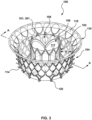
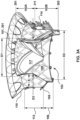
- FIG. 3 A perspective view of a heart valve prosthesis 100 in accordance with an aspect of the disclosure is shown in FIG. 3 , and a sectional view of the heart valve prosthesis 100, taken along line A-A of FIG. 3 , is shown in FIG. 3A .
- the heart valve prosthesis 100 is configured to be compressed into a reduced-diameter delivery configuration (not shown) and to return to an expanded, deployed configuration, as shown in FIG. 3A .
- the heart valve prosthesis 100 when in the delivery configuration, has a low profile suitable for delivery to and deployment within a native mitral valve via a suitable delivery catheter that may be tracked to the deployment site of the native mitral valve of a heart via any one of a transseptal, retrograde, or transapical approach.
- the heart valve prosthesis 100 includes a valve support 102 at least partially surrounded by an anchor element 104.
- the valve support 102 is a hollow stent-like structure that defines a lumen 109 from an inflow end 101 of the valve support 102 to an outflow end 103 of the valve support 102.
- the valve support 102 has a first or upstream segment 102A and a second or downstream segment 102B, with "upstream” and “downstream” referring to intended deployed positions of the respective segments within a native mitral valve of a heart relative to blood flow therethrough.
- the upstream segment 102A of the valve support 102 is configured to support a prosthetic valve component 108 therein, which will be described in more detail below.
- the upstream segment 102A may be described as having a substantially cylindrical shape with a first or upstream end 301 of the upstream segment 102A defining the inflow end 101 of the valve support 102.
- a second or downstream end 311 of the upstream segment 102A of the valve support 102 is coextensive with a first or upstream end 311 of the downstream segment 102B of the valve support 102, and a second or downstream end 303 of the downstream segment 102B defines the outflow end 103 of the valve support 102.
- the first end 301 of the upstream segment 102A that defines the inflow end 101 of the valve support 102 has an outer diameter D1
- the second end 303 of the downstream segment 102B that defines the outflow end 103 of the valve support 102 has an outer diameter D2 that is greater than the outer diameter D1.
- the second end 311 of the upstream segment 102A and the coextensive first end 311 of the downstream segment 102B have an outer diameter D3 that may be equal to or less than the outer diameter D 1.
- the outer diameter D1 of the upstream segment 102A may be described as being constant along the entire length of the upstream segment 102A from the first end 301 to the second end 311 thereof.
- the outer diameter D3 of the coextensive first end 311 of the downstream segment 102B is also equal to the outer diameter D1, such that the downstream segment 102B is flared outwardly from the outer diameter D1 at its first end 311 to the outer diameter D2 at its second end 303, with the outer diameter D2 being greater than the outer diameter D1 as stated above.
- an upstream segment 102A having a constant outer diameter D1 along its entire length may be described to have the form of a hollow, substantially cylindrical shape
- a downstream segment 102B that flares radially, outwardly from a first end 311 having the outer diameter D1 to a second end having the outer diameter D2 may be described to have the form of a hollow, substantially frustoconical shape.
- an upstream segment 102A having a constant outer diameter D1 along its entire length may be described to have the form of a hollow, substantially cylindrical shape
- a downstream segment 102B that flares radially, outwardly from a first end 311 having the outer diameter D1 to a second end having the outer diameter D2 may be described to have the form of a hollow, substantially trumpet shaped.
- a valve support 102 in which an outer diameter D3 is less than an outer diameter D1, an upstream segment 102A gradually tapers along its length from its first end 301 having the outer diameter D1 to its second end 311 having the outer diameter D3.
- a valve support 102 having a tapered inflow profile may improve hemodynamics as the tapered inflow profile may promote transvalvular blood flow and reduce the possibility of paravalvular leakage.
- the coextensive first end 311 of the downstream segment 102B also has the outer diameter D3 that is less than the outer diameter D1, such that the downstream segment 102B is flared radially, outwardly from the outer diameter D3 at its first end 311 to the outer diameter D2 at its second end 303, with the outer diameter D2 being greater than the each of the outer diameters D1 and D3.
- an anchor element 104 of a heart valve prosthesis 100 is configured to mechanically isolate an upstream segment 102A of a valve support 102 from the anchor element 104 when the heart valve prosthesis 100 is deployed within a smaller, substantially elliptically shaped native mitral valve annulus.
- the anchor element 104 is a hollow, stent-like structure that includes a tissue fixation ring 112 and a plurality of connectors 106.
- the tissue fixation ring 112 is a substantially cylindrically-shaped structure that is configured to engage heart tissue at or below an annulus of a native heart valve, such as an annulus of a native mitral valve.
- the tissue fixation ring 112 may be configured to engage subannular tissue, such as inward-facing surfaces of the valve leaflets, as shown in FIG. 4A .
- the tissue fixation ring 112 functions as an anchor for the heart valve prosthesis 100 to secure its deployed position within a native annulus.
- the tissue fixation ring 112 includes one or more cleats or prongs 114 that extend outward from an exterior side of the tissue fixation ring 113 to engage heart tissue.
- a tissue fixation ring 113 may employ barbs, spikes, or other tissue fixation mechanisms for engaging heat tissue.
- the tissue fixation ring 112 is radially spaced from the upstream segment 102A of the valve support 102 a distance S in an undeployed state, as shown in FIGS. 3 and 3A , and is at least partially deformable into a non-circular shape to adapt to a shape of an implantation site in a deployed state, such as deforming into a substantially elliptical shape when deployed within a smaller native mitral valve annulus.
- a tissue fixation ring 112 and an upstream segment 102A of a valve support 102 are sized relative to each other to provide a distance S therebetween so as to be configured to prevent contact therebetween, when the heart valve prosthesis is deployed, and to thereby mechanically isolate the upstream segment 102A of the valve support 102 from the anchor element 104.
- the plurality of connectors 106 are angled radially inward from a downstream end 105 of the tissue fixation ring 112 to attach to the outflow end 103 of the valve support 102.
- an outflow end 103 of the valve support 102 may be attached to downstream ends 115 of the plurality of connectors 106 by a plurality of rivets 120.
- valve support 102 and the plurality of connectors 106 of the fixation ring 112 may be coupled to each other by any of a variety of methods known in the art that, by way of example and not limitation, may include suturing, soldering, welding, staples, or other fasteners, mechanical interlocking, snap fit, friction or interference fit, or any combination thereof.
- Each of the connectors 106 of the fixation ring 112 may be described as having an inwardly curved, substantially V-shape with downstream ends 115 of the plurality of connectors 106 being respective vertices of the V-shape.
- the plurality of connectors 106 may be formed by inwardly curving or bending downstream portions, or downstream halves, of a last row of cells of the stent-like structure of the anchor element 104.
- the plurality of connectors 106 may extend radially inwardly and downwardly from respective upstream ends, which are coextensive with the downstream end 105 of the tissue fixation ring, to the respective downstream ends 115 thereof and are so configured to permit upward flexion of the plurality of connectors 106, after implantation, to accommodate any radial expansion of the tissue fixation ring 112 that may occur after deployment due to an increase in size of the native annulus, which may occur, for example, due to tissue remodeling after valve replacement, natural growth until adulthood, and/or potential disease progression.
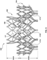
- FIG. 4 depicts a frame 430 of a heart valve prosthesis 100 in accordance with an embodiment hereof, the frame 430 including a valve support 102 and an anchor element 104.
- the valve support 102 of the frame 430 is formed of a stent-like structure having honeycomb-shaped cells and the anchor element 104 of the frame 430 is formed of a stent-like structure having closed diamond-shaped cells.
- each of a valve support 502 and an anchor element 104 of a frame 530 is formed of a stent-like structure having closed diamond-shaped cells.
- an outer diameter OD1 of an outflow end 432 of the frame 430 is a measurement that spans a distance between outer sides of downstream ends 115A, 115B of respective connectors 106 on opposing sides of the anchor element 104.
- an outer diameter OD2 of an upstream end 107 of the anchor element 104 is a measurement that spans a distance between outer sides of the upstream end 107 on opposing sides of the anchor element 104, and is the broadest point of the anchor element 104.
- a heart valve prosthesis 100 with a frame 430 having an outer diameter OD1 of about 30+/-0.5 mm and an outer diameter OD2 of about 36+/-0.5 mm is sized for implantation within a patient having a smaller native mitral valve annulus.
- a frame 430 for use in compact transcatheter heart valve prostheses in accordance with embodiments hereof has a shorter overall height H1 and a reduced cone height H2 than conventional heart valve prostheses, which reduces protrusion of the compact transcatheter heart valve prostheses below a valve plane of the native mitral valve into the left ventricle.
- a heart valve prosthesis 100 with a frame 430 having a shorter overall height H1 of about 16.2mm+/- 0.5mm and a reduced cone height H2 of about 5.4mm+/-0.5mm is sized for implantation within a patient having a smaller native mitral valve annulus to thereby reduce or prevent left ventricular outflow track (LVOT) obstruction.
- LVOT left ventricular outflow track
- the compact transcatheter heart valve prostheses perform with equivalent, or, in some cases, improved hemodynamic performance than their larger and taller counterparts.
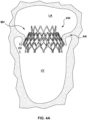
- FIG. 4A depicts a side view of the frame 430 of FIG.
- FIG. 4 depicts a sectional view of a portion of the frame 430 of FIG. 4A in the deployed state in accordance with an aspect of the disclosure.
- FIG. 4A only shows a frame 430 deployed within the mitral valve MV for ease of illustration, and one of ordinary skill in the art would readily recognize how the illustration applies to a deployed state of a compact heart valve prosthesis 100 as shown and described with reference to FIGS. 3 and 3A-3D .
- a cone height H2 of the frame 430 refers to a measurement between the downstream end 105 of the tissue fixation ring 112 and the outflow end 432 of the frame 430.
- the cone height H2 encompasses the plurality of connectors 106 of the anchor element 104.
- a cone height H2 is relatively short and a remainder of the frame 430 sits at or near a valve plane of the annulus AN, with the entirety of a deployed compact heart valve prosthesis 100 being shifted upwardly toward the left atrium LA, to thereby reduce or prevent left ventricular outflow track (LVOT) obstruction.
- LVOT left ventricular outflow track
- the reduced cone height H2 of the frame 430 also minimizes contact and/or interaction with chordae tendineae and the papillary muscles, and provides advantages in patients with small left ventricles, who heretofore may have been screened out from receiving a mitral valve prosthesis because their annuli are too small or because there would be too much LVOT obstruction.
- a tissue fixation ring 112 of a frame 430 is radially spaced from an upstream segment 102A of a valve support 102 a distance S in an undeployed state, and is at least partially deformable into a non-circular shape to adapt to a shape of the native mitral valve annulus in a deployed state.
- the tissue fixation ring 112 does not make contact with the upstream segment 102A of the valve support 102, as shown in FIG. 4B , and thereby mechanical isolation between the upstream segment 102A of the valve support 102 from the anchor element 104 is maintained when the compact heart valve prosthesis 100 is implanted in vivo.
- the brim element 110 includes overlapping, 180 degree out of phase sinusoidal wire forms that are attached and hinged to the anchor element 104 by a suitable biocompatible low-profile fabric 119 used in bioprosthetic implants namely endovascular grafts, heart valves or left atrial appendage devices to promote bio-integration, such as woven polyethylene terephthalate (PET) fabric.
- PET polyethylene terephthalate
- the brim element 110 may act as an atrial retainer, if present, and to serve such a function the brim element 110 may be configured to engage tissue above the native annulus AN, such as a supra-annular surface or some other tissue in the left atrium, to thereby inhibit downstream migration of a prosthetic heart valve 100, for e.g., during atrial systole.
- a heart valve prosthesis 100 in accordance with aspects of the disclosure includes a prosthetic valve component 108, as previously noted above.
- FIG. 3B depicts a perspective view of a valve support 102 with a prosthetic valve component 108 secured therein, the valve support 102 being shown in FIG. 3B removed from the remainder of the heart valve prosthesis 100 shown in FIG. 3 for ease of illustration.
- FIG. 3C depicts an atrial view of the heart valve prosthesis 100 shown in FIG. 3
- FIG. 3D depicts a ventricular view of the heart valve prosthesis 100 shown in FIG. 3 .
- the prosthetic valve component 108 includes valve leaflets 117, for e.g., three valve leaflets 117, that are disposed to coapt within the narrow upstream segment 102A of the valve support 102 with the commissures 117A, 117B, 117C of the valve leaflets 117 being secured within the wider downstream segment 102B of the valve support 102, such that the valve leaflets 117 open into the wider downstream segment 102B of the valve support 102 during diastole.
- valve leaflets 117 for e.g., three valve leaflets 117, that are disposed to coapt within the narrow upstream segment 102A of the valve support 102 with the commissures 117A, 117B, 117C of the valve leaflets 117 being secured within the wider downstream segment 102B of the valve support 102, such that the valve leaflets 117 open into the wider downstream segment 102B of the valve support 102 during diastole.
- the leaflet commissures 117A, 117B, 117C being arranged within the wider downstream segment 102B provides the prosthetic valve component 108 with a larger effective orifice area (EOA) by allowing the valve leaflets 117 to open more without interacting with the valve support 102.
- EOA effective orifice area
- the prosthetic valve component 108 in an open state during diastole, may have an effective orifice area greater than about 1.6 cm 2 .
- the valve leaflets 117 may be formed of various flexible materials including, but not limited to natural pericardial material such as tissue from bovine, equine or porcine origins, or synthetic materials such as polytetrafluoroethylene (PTFE), DACRON ® polyester, pyrolytic carbon, or other biocompatible materials.
- natural pericardial material such as tissue from bovine, equine or porcine origins
- synthetic materials such as polytetrafluoroethylene (PTFE), DACRON ® polyester, pyrolytic carbon, or other biocompatible materials.
- PTFE polytetrafluoroethylene
- DACRON ® polyester DACRON ® polyester
- pyrolytic carbon or other biocompatible materials.
- FIG. 5 depicts a prosthetic valve component 108 secured within a valve support 502 of a frame 530.
- the valve component 108 includes valve leaflets 117 being disposed to coapt within a narrow upstream segment 502A of the valve support 502 and the commissures 117A, 117B, 117C of the valve leaflets 117 being secured within a wider downstream segment 502B of the valve support 502, such that the valve leaflets 117 open into the wider downstream segment 502B of the valve support 502 during diastole.
- a valve support 102 and a tissue fixation ring 112 may be fully lined by a low-profile fabric 119 designed to provide sealing, such as that used in bioprosthetic implants namely endovascular grafts, heart valves or left atrial appendage devices to promote bio-integration, such as woven polyethylene terephthalate (PET) fabric.
- a woven textile may be employed that will act as a platform for subsequent tissue ingrowth.
- a low-profile fabric 119 for attaching to the valve support 102 and the tissue fixation ring 104 may be two separate pieces or types of fabric in order to mitigate leaks and reduce manufacturing time.
- Any of a frame, valve support, tissue fixation ring, plurality of connectors, etc. described herein as an element of a heart valve prothesis 100 may be made from any number of suitable biocompatible materials, e.g., stainless steel, nickel titanium alloys such as Nitinol TM , cobalt chromium alloys such as MP35N, other alloys such as ELGILOY ® (Elgin, Ill.), various polymers, pyrolytic carbon, silicone, polytetrafluoroethylene (PTFE), or any number of other materials or combination of materials.
- suitable biocompatible materials e.g., stainless steel, nickel titanium alloys such as Nitinol TM , cobalt chromium alloys such as MP35N, other alloys such as ELGILOY ® (Elgin, Ill.), various polymers, pyrolytic carbon, silicone, polytetrafluoroethylene (PTFE), or any number of other materials or combination of materials.
- a suitable biocompatible material would be selected to provide a heart valve prothesis 100 that is configured to be compressed into a reduced-diameter delivery configuration for transcatheter delivery to a native valve, whereby release from a delivery catheter returns the prosthesis to an expanded, deployed configuration.
Landscapes
- Health & Medical Sciences (AREA)
- Cardiology (AREA)
- Engineering & Computer Science (AREA)
- Biomedical Technology (AREA)
- Heart & Thoracic Surgery (AREA)
- Transplantation (AREA)
- Oral & Maxillofacial Surgery (AREA)
- Vascular Medicine (AREA)
- Life Sciences & Earth Sciences (AREA)
- Animal Behavior & Ethology (AREA)
- General Health & Medical Sciences (AREA)
- Public Health (AREA)
- Veterinary Medicine (AREA)
- Prostheses (AREA)
Abstract
Description
- The present technology is generally related to prosthetic heart valve devices, and in particular is directed to prosthetic heart valve devices for percutaneous repair and/or replacement of native mitral valves.
- The human heart is a four chambered, muscular organ that provides blood circulation through the body during a cardiac cycle. The four main chambers include the right atrium and right ventricle which supplies the pulmonary circulation, and the left atrium and left ventricle which supplies oxygenated blood received from the lungs into systemic circulation. To ensure that blood flows in one direction through the heart, atrioventricular valves (tricuspid and mitral valves) are present between the junctions of the atrium and the ventricles, and semi-lunar valves (pulmonary valve and aortic valve) govern the exits of the ventricles leading to the lungs and the rest of the body. These valves contain leaflets or cusps that open and shut in response to blood pressure changes caused by the contraction and relaxation of the heart chambers. The valve leaflets move apart from each other to open and allow blood to flow downstream of the valve, and coapt to close and prevent backflow or regurgitation in an upstream manner.
- Diseases associated with heart valves, such as those caused by damage or a defect, can include stenosis and valvular insufficiency or regurgitation. For example, valvular stenosis causes the valve to become narrowed and hardened which can prevent blood flow to a downstream heart chamber from occurring at the proper flow rate and may cause the heart to work harder to pump the blood through the diseased valve. Valvular insufficiency or regurgitation occurs when the valve does not close completely, allowing blood to flow backwards, thereby causing the heart to be less efficient. A diseased or damaged valve, which can be congenital, age-related, drug-induced, or in some instances, caused by infection, can result in an enlarged, thickened heart that loses elasticity and efficiency. Some symptoms of heart valve diseases can include weakness, shortness of breath, dizziness, fainting, palpitations, anemia and edema, and blood clots which can increase the likelihood of stroke or pulmonary embolism. Symptoms can often be severe enough to be debilitating and/or life threatening.
- Heart valve prostheses have been developed for repair and replacement of diseased and/or damaged heart valves. Such heart valve prostheses can be percutaneously delivered and deployed at the site of the diseased heart valve through catheter-based delivery systems. Such heart valve prostheses can be delivered while in a radially compressed configuration so that the valve prosthesis can be advanced through the patient's vasculature. Once positioned at the treatment site, the valve prosthesis can be expanded to engage tissue at the diseased heart valve region to, for instance, hold the valve prosthesis in position.
- While these valve prostheses offer minimally invasive methods for heart valve repair and/or replacement, challenges remain to providing heart valve prostheses for patients with smaller native heart valves than the general population, for example, due to either having a smaller adult stature than the general population, or to being a child or adolescent. In an adult patient population that may benefit from a mitral valve prosthesis for treating mitral regurgitation, for instance, as many as 7% may be screened out due to having native mitral valves with annulus perimeters of between 89 mm to 101 mm that are currently considered too small to accept known mitral valve prostheses, which are sized for implantation within native mitral valves having annulus perimeters of between 101 mm to 119 mm. Such native mitral valves having smaller perimeter annuli tend to be more elliptical in shape, than native mitral valves having larger perimeter annuli, resulting in currently known mitral valve prostheses also being unsuitable for implantation within the smaller perimeter annuli due to those prostheses being substantially oversized in the anterior to posterior direction.
- Accordingly, there is a need for a mitral valve prosthesis that may be percutaneously delivered and deployed at the site of a diseased mitral valve in a patient with a native mitral valve that is too small to accept known mitral valve prosthesis.
- The devices and methods of this disclosure generally relate to a heart valve prosthesis that is configured to be implanted within a native heart valve having a smaller perimeter annuli with a generally elliptical shape.
- In one aspect, the present disclosure provides a heart valve prosthesis that includes a valve support with upstream and downstream segments relative to blood flow through a native heart valve of a human heart. The upstream segment of the valve support is configured to support a prosthetic valve component and defines an inflow end of the valve support having a first outer diameter. The downstream segment of the valve support defines an outflow end of the valve support having a second outer diameter that is greater than the first outer diameter. The heart valve prosthesis further includes an anchor element that surrounds the valve support. A plurality of connectors form a downstream portion of the anchor element, the plurality of connectors being angled inward toward the valve support to be attached to the outflow end of the valve support. The anchor element is spaced from the upstream segment of the valve support to mechanically isolate the upstream segment of the valve support from the anchor element.
- In another aspect, which may be combined with any of the other aspects noted herein, the disclosure provides a heart valve prosthesis with a first outer diameter of an upstream segment of a valve support that is constant from a first end of the upstream segment, which defines an inflow end of the valve support, to a second end of the upstream segment.
- In another aspect, which may be combined with any of the other aspects noted herein, the disclosure provides a heart valve prosthesis with a downstream end of an upstream segment of a valve support that is adjacent a upstream end of a downstream segment of the valve support, such that the upstream end of the downstream segment has a first outer diameter and a longitudinally opposite downstream end of the downstream segment, which defines an outflow end of the valve support, has a second outer diameter that is greater than the first outer diameter.
- In another aspect, which may be combined with any of the other aspects noted herein, the disclosure provides a heart valve prosthesis with a downstream segment of a valve support that is flared outwardly from a first end to a second end thereof, with the first end of the downstream segment having a first outer diameter and the second end of the downstream segment, which defines an outflow end of the valve support, having a second outer diameter that is greater than the first outer diameter.
- In another aspect, which may be combined with any of the other aspects noted herein, the disclosure provides a heart valve prosthesis with an upstream segment of a valve support that tapers from a first end of the upstream segment having a first outer diameter, which defines an inflow end of the valve support, to a second end of the upstream segment having a second outer diameter that is smaller than the first outer diameter.
- In another aspect, which may be combined with any of the other aspects noted herein, the disclosure provides a heart valve prosthesis with an upstream segment of a valve support tapered inwardly from upstream to downstream ends thereof such that the downstream end of the upstream segment of a valve support, with a first outer diameter, is adjacent to an upstream end of a downstream segment of the valve support with the first outer diameter. The downstream segment is flared outwardly from the upstream end to a downstream end thereof, with the downstream end of the downstream segment, which defines an outflow end of the valve support, having a second outer diameter that is larger than the first outer diameter.
- In another aspect, which may be combined with any of the other aspects noted herein, the disclosure provides a heart valve prosthesis with a tissue fixation ring that forms an upstream portion of an anchor element, the tissue fixation ring being configured to engage heart tissue at or below a native annulus of the native heart valve.
- In another aspect, which may be combined with any of the other aspects noted herein, the disclosure provides a heart valve prosthesis with an anchor element having a tissue fixation ring that is radially spaced from an upstream segment of a valve support a distance S in an undeployed state. The tissue fixation ring being configured to be at least partially deformable into a non-circular shape to adapt to a shape of an implantation site in a deployed state, such that the tissue fixation ring does not make contact with the upstream segment of the valve support, and thereby mechanically isolates the upstream segment of the valve support from the anchor element when implanted in vivo.
- In another aspect, which may be combined with any of the other aspects noted herein, the disclosure provides a heart valve prosthesis with a plurality of connectors of an anchor element that are angled inward from a tissue fixation ring of the anchor element.
- In another aspect, which may be combined with any of the other aspects noted herein, the disclosure provides a heart valve prosthesis with a plurality of connectors of an anchor element that are angled inward from a tissue fixation ring of the anchor element, the plurality of connectors being configured to flex upward, after implantation, to accommodate any radial expansion of the tissue fixation ring caused by an increase in size of an implantation site, such as a native annulus, that may occur after deployment.
- In another aspect, which may be combined with any of the other aspects noted herein, the disclosure provides a heart valve prosthesis with an anchor element having a tissue fixation ring that includes one or more cleats extending outward from the tissue fixation ring to engage heart tissue upon implantation.
- In another aspect, which may be combined with any of the other aspects noted herein, the disclosure provides a heart valve prosthesis with a prosthetic valve component disposed within an upstream segment of a valve support such that valve leaflets of the prosthetic valve component open into a downstream segment of the valve support during diastole.
- In another aspect, which may be combined with any of the other aspects noted herein, the disclosure provides a heart valve prosthesis with a prosthetic valve component disposed within an upstream segment of a valve support such that valve leaflets of the prosthetic valve component achieve an open state having an effective orifice area greater than about 1.6 cm2 during diastole.
- In another aspect, which may be combined with any of the other aspects noted herein, the disclosure provides a heart valve prosthesis with a frame having a valve support that is formed of a stent-like structure having one of honeycomb-shaped and closed diamond-shaped cells.
- In another aspect, which may be combined with any of the other aspects noted herein, the disclosure provides a heart valve prosthesis with a frame having an anchor element that is formed of a stent-like structure having diamond-shaped cells.
- In another aspect, which may be combined with any of the other aspects noted herein, the disclosure provides a heart valve prosthesis with an outflow end of a valve support being attached, by a plurality of rivets, to a plurality of connectors of an anchor element.
- In another aspect, which may be combined with any of the other aspects noted herein, the disclosure provides a heart valve prosthesis with an anchor element provided with a plurality of connectors, with each of the connectors having an inwardly curved substantially V-shape.
- In another aspect, which may be combined with any of the other aspects noted herein, the disclosure provides a heart valve prosthesis with a first outer diameter and a second outer diameter. In an embodiment, the first outer diameter at an outflow end of the heart valve prosthesis is about 30 mm and the second outer diameter at an upstream end of an anchor element is about 36 mm, such that the heart valve prosthesis is sized for implantation within a patient having a smaller native annulus.
- Further disclosed herein is a heart valve prosthesis that is configured to be implanted within a native heart valve having a smaller perimeter annuli with a generally elliptical shape.
- Further disclosed herein is the subject-matter of the following clauses:
- 1. A heart valve prosthesis, comprising:
- a valve support having an upstream segment and a downstream segment relative to blood flow through a native heart valve of a human heart,
- the upstream segment configured to support a prosthetic valve component therein and defining an inflow end of the valve support having a first outer diameter, and
- the downstream segment defining an outflow end of the valve support having a second outer diameter that is greater than the first outer diameter; and
- an anchor element that surrounds the valve support,
- the anchor element having a plurality of connectors forming a downstream portion thereof that are angled inward toward the valve support and are attached to the outflow end of the valve support, and
- the anchor element being spaced from the upstream segment of the valve support to mechanically isolate the upstream segment of the valve support from the anchor element.
- a valve support having an upstream segment and a downstream segment relative to blood flow through a native heart valve of a human heart,
- 2. The heart valve prosthesis of clause 1, wherein the first outer diameter of the upstream segment is constant from a first end of the upstream segment, which defines the inflow end of the valve support, to a second end of the upstream segment.
- 3. The heart valve prosthesis of clause 2, wherein the second end of the upstream segment is adjacent a first end of the downstream segment, such that the first end of the downstream segment has the first outer diameter and a second end of the downstream segment, which defines the outflow end of the valve support, has the second outer diameter.
- 4. The heart valve prosthesis of clause 2, wherein the downstream segment is flared outwardly from a first end to a second end thereof, with the first end of the downstream segment having the first outer diameter and the second end of the downstream segment, which defines the outflow end of the valve support, having the second outer diameter.
- 5. The heart valve prosthesis of any of the preceding clauses, wherein the upstream segment tapers from a first end of the upstream segment, which defines the inflow end of the valve support, having the first outer diameter to a second end of the upstream segment having a third outer diameter that is smaller than the first and second outer diameters.
- 6. The heart valve prosthesis of
clause 5, wherein the second end of the upstream segment is adjacent a first end of the downstream segment, such that the first end of the downstream segment has the third outer diameter, the downstream segment being flared outwardly from the first end to a second end thereof, with the second end of the downstream segment, which defines the outflow end of the valve support, having the second outer diameter. - 7. The heart valve prosthesis of any of the preceding clauses, wherein the anchor element includes a tissue fixation ring that forms an upstream portion thereof that is configured to engage heart tissue at or below a native annulus of the native heart valve.
- 8. The heart valve prosthesis of clause 7, wherein the tissue fixation ring is radially spaced from the upstream segment of the valve support a distance in the undeployed state and is at least partially deformable into a non-circular shape to adapt to a shape of an implantation site in a deployed state, without making contact with the upstream segment of the valve support, to mechanically isolate the upstream segment of the valve support from the anchor element.
- 9. The heart valve prosthesis of clause 7, wherein the plurality of connectors are angled inward from the tissue fixation ring.
- 10. The heart valve prosthesis of clause 9, wherein the plurality of connectors are configured to flex upward, after implantation, to accommodate any radial expansion of the tissue fixation ring due to an increase in size of the native annulus with patient growth.
- 11. The heart valve prosthesis of clause 7, wherein the tissue fixation ring includes one or more cleats that extend outward therefrom to engage the heart tissue.
- 12. The heart valve prosthesis of any of the preceding clauses, further comprising a prosthetic valve component disposed within the upstream segment of the valve support such that valve leaflets of the prosthetic valve component open into the downstream segment of the valve support during diastole.
- 13. The heart valve prosthesis of clause 12, wherein in an open state during diastole the prosthetic valve component has an effective orifice area greater than about 1.6 cm2.
- 14. The heart valve prosthesis of any of the preceding clauses, wherein the outflow end of the valve support is attached to the plurality of connectors by a plurality of rivets, and/or wherein each of the plurality of connectors has an inwardly curved substantially V-shape, and/or wherein the valve support and the anchor element comprise a frame of the heart valve prosthesis.
- 15. The heart valve prosthesis of clause 16, wherein the valve support of the frame is formed of a stent-like structure having honeycomb-shaped cells and the anchor element is formed of a stent-like structure having closed diamond-shaped cells; or wherein each of the valve support and the anchor element of the frame is formed of a stent-like structure having closed diamond-shaped cells; or wherein the frame has a first outer diameter at an outflow end of the frame that is about 30 mm and has a second outer diameter at an upstream end of the anchor element that is about 36 mm, whereby the heart valve prosthesis is sized for implantation within a patient having a smaller native mitral valve annulus.
- The details of one or more aspects of the disclosure are set forth in the accompanying drawings and the description below. Other features, objects, and advantages of the techniques described in this disclosure will be apparent from the description and drawings, and from the claims.
- The foregoing and other features and advantages of the invention will be apparent from the following description of embodiments thereof as illustrated in the accompanying drawings. The accompanying drawings, which are incorporated herein and form a part of the specification, further serve to explain the principles of the invention and to enable a person skilled in the pertinent art to make and use the invention. The drawings are not to scale.
-
FIG. 1 depicts a schematic sectional illustration of a heart having native valve structures. -
FIG. 2 depicts a schematic sectional illustration of a left ventricle of a heart showing anatomical structures and a native mitral valve. -
FIG. 2A depicts a schematic illustration of a native mitral valve of a heart showing normal closure of native mitral valve leaflets. -
FIG. 3 depicts a perspective view of a heart valve prosthesis in accordance with an aspect of the disclosure. -
FIG. 3A depicts a sectional view of the heart valve prosthesis ofFIG. 3 , taken along line A-A thereof. -
FIG. 3B depicts a perspective view of a valve support of the heart valve prosthesis ofFIG. 3 with a prosthetic valve component secured therein in accordance with an aspect of the disclosure. -
FIG. 3C depicts an atrial view of the heart valve prosthesis shown inFIG. 3 in accordance with an aspect of the disclosure. -
FIG. 3D depicts a ventricular view of the heart valve prosthesis shown inFIG. 3 in accordance with an aspect of the disclosure. -
FIG. 4 depicts a side view of a frame of a heart valve prosthesis in an undeployed state in accordance with an aspect of the disclosure. -
FIG. 4A depicts a side view of the frame ofFIG. 4 in a deployed state in accordance with an aspect of the disclosure. -
FIG. 4B depicts a sectional view of a portion of the frame ofFIG. 4A in the deployed state in accordance with an aspect of the disclosure. -
FIG. 5 depicts a side view of a frame of a heart valve prosthesis in accordance with an aspect of the disclosure. - Specific embodiments of the present invention are now described with reference to the figures, wherein like reference numbers indicate identical or functionally similar elements. The terms "distal" and "proximal", when used in the following description to refer to a native vessel, native valve, or a device to be implanted into a native vessel or native valve, such as a heart valve prosthesis, are with reference to the direction of blood flow. Thus, "distal" and "distally" refer to positions in a downstream direction with respect to the direction of blood flow and the terms "proximal" and "proximally" refer to positions in an upstream direction with respect to the direction of blood flow.
- The following detailed description is merely exemplary in nature and is not intended to limit the invention or the application and uses of the invention. Although the description of embodiments hereof is in the context of the treatment of heart valves such as the pulmonary, aortic, mitral, or tricuspid valve, the invention may also be used in any other body passageways where it is deemed useful. Furthermore, there is no intention to be bound by any expressed or implied theory presented in the preceding technical field, background, brief summary or the following detailed description.
- Prosthetic heart valve devices and methods described herein provide a heart valve replacement device that is sized to fit within a native mitral valve that is screened as too small, and likely too elliptically-shaped, to accept known mitral valve prosthesis. In accordance with embodiments hereof, the prosthetic heart valve devices may be configured for implantation within native mitral valves with annulus perimeters of between about 89 mm to about 101 mm. The prosthetic heart valve devices described herein have the requisite flexibility to adapt and conform to such native mitral valve anatomy while mechanically isolating a prosthetic heart valve from an anchoring portion of the device, particularly addressing oversizing that may occur in the anterior-posterior direction of an elliptically-shaped, smaller native mitral valve. The prosthetic heart valve devices described herein effectively absorb the distorting forces applied by the native anatomy with sufficient structural strength and integrity to withstand the dynamic conditions of the heart over time. The prosthetic heart valve devices described herein are further configured to be delivered in a less-invasive transcatheter procedure.
-
FIG. 1 is a schematic sectional illustration of a heart H that depicts the four heart chambers (right atria RA, right ventricle RV, left atria LA, left ventricle LV) and native valve structures (tricuspid valve TV, mitral valve MV, pulmonary valve PV, aortic valve AV).FIG. 2 is a schematic sectional illustration of a left ventricle LV of a heart H showing anatomical structures and a native mitral valve MV. Referring toFIGS. 1 and2 together, the heart H comprises the left atrium LA that receives oxygenated blood from the lungs via the pulmonary veins. The left atrium LA pumps the oxygenated blood through the mitral valve MV and into the left ventricle LV during ventricular diastole. The left ventricle LV contracts during systole and blood flows outwardly through the aortic valve AV, into the aorta and to the remainder of the body. - In a healthy heart, the valve leaflets LF of the mitral valve MV meet evenly at the free edges or "coapt" to close and prevent back flow of blood during contraction of the left ventricle LV. Referring to
FIG. 2 , the valve leaflets LF attach the surrounding heart structure via a dense fibrous ring of connective tissue called an annulus AN which is distinct from both the leaflet tissue LF as well as the adjoining muscular tissue of the heart wall. In general, the connective tissue at the annulus AN is more fibrous, tougher and stronger than leaflet tissue. The flexible leaflet tissue of the mitral valve leaflets LF are connected to papillary muscles PM, which extend upwardly from the lower wall of the left ventricle LV and the interventricular septum IVS, via branching tendons called chordae tendineae CT. In a heart H having a mitral valve MV in which the valve leaflets LF do not sufficiently coapt or meet, leakage from the left ventricle LV into the left atrium LA will occur. Several structural defects can cause the mitral valve leaflets LF to prolapse in this manner, and subsequent regurgitation to occur, including ruptured chordae tendineae CT, impairment of papillary muscles PM, e.g., due to ischemic heart disease, and enlargement of the heart and/or mitral valve annulus AN, e.g., cardiomyopathy. -
FIG. 2A further illustrates the shape and relative sizes of valve leaflets LF of a mitral valve MV, and it may be seen that the overall valve has a generally "D"-shape or kidney-like shape with a long axis LA and a short axis SA. The line of coaptation C of the valve leaflets LF is curved or C-shaped, thereby defining a relatively large anterior leaflet AL and substantially smaller posterior leaflet PL. Both valve leaflets appear generally crescent-shaped from the superior or atrial side, with the anterior leaflet AL being substantially wider in the middle of the valve than the posterior leaflet. As illustrated inFIG. 2A , the valve leaflets LF join together at corners called the anterolateral commissure AC and posteromedial commissure PC, respectively, at the opposing ends of the line of coaptation C. - For healthy adult humans, with reference to the long axis LA and the short axis SA shown in
FIG. 2A , the long axis LA is typically within a range from about 33.6±6.0 mm to about 42.2±2.6 mm, with a standard deviation in a range of 2.6 mm to 6.0 mm, and the short axis SA is typically within a range from about 23.8±4.0 mm to about 33.7±3.5 mm, with a standard deviation in a range of 2.2 mm to 4.0 mm. However, with adult patients having decreased mitral valve function these values can be larger, for example, LA can be within a range from about 38.5±3.2 mm to about 52.7±3.9 mm, with a standard deviation in a range of 2.9 mm to 6.0 mm, and SA can be within a range from about 26.7±2.8 mm to about 37.2±0.4 mm, with a standard deviation in a range of 0.4 mm to 6.4 mm. For a patient population with diseased smaller native mitral valves to be treated with the prosthetic heart valve devices described herein, these values may be, for example, LA within a range from about 30 mm to 34 mm and SA within a range from about 24 mm to about 32 mm. - A perspective view of a
heart valve prosthesis 100 in accordance with an aspect of the disclosure is shown inFIG. 3 , and a sectional view of theheart valve prosthesis 100, taken along line A-A ofFIG. 3 , is shown inFIG. 3A . Theheart valve prosthesis 100 is configured to be compressed into a reduced-diameter delivery configuration (not shown) and to return to an expanded, deployed configuration, as shown inFIG. 3A . In accordance with embodiments hereof, when in the delivery configuration, theheart valve prosthesis 100 has a low profile suitable for delivery to and deployment within a native mitral valve via a suitable delivery catheter that may be tracked to the deployment site of the native mitral valve of a heart via any one of a transseptal, retrograde, or transapical approach. - In an aspect of the disclosure, the
heart valve prosthesis 100 includes avalve support 102 at least partially surrounded by ananchor element 104. Thevalve support 102 is a hollow stent-like structure that defines alumen 109 from an inflow end 101 of thevalve support 102 to anoutflow end 103 of thevalve support 102. In an aspect of the disclosure, thevalve support 102 has a first orupstream segment 102A and a second ordownstream segment 102B, with "upstream" and "downstream" referring to intended deployed positions of the respective segments within a native mitral valve of a heart relative to blood flow therethrough. - The
upstream segment 102A of thevalve support 102 is configured to support aprosthetic valve component 108 therein, which will be described in more detail below. Theupstream segment 102A may be described as having a substantially cylindrical shape with a first orupstream end 301 of theupstream segment 102A defining the inflow end 101 of thevalve support 102. A second ordownstream end 311 of theupstream segment 102A of thevalve support 102 is coextensive with a first orupstream end 311 of thedownstream segment 102B of thevalve support 102, and a second ordownstream end 303 of thedownstream segment 102B defines theoutflow end 103 of thevalve support 102. - In an aspect of the disclosure, the
first end 301 of theupstream segment 102A that defines the inflow end 101 of thevalve support 102 has an outer diameter D1, and thesecond end 303 of thedownstream segment 102B that defines theoutflow end 103 of thevalve support 102 has an outer diameter D2 that is greater than the outer diameter D1. In various aspects of the disclosure, thesecond end 311 of theupstream segment 102A and the coextensivefirst end 311 of thedownstream segment 102B have an outer diameter D3 that may be equal to or less than the outer diameter D 1. - In an embodiment of a
valve support 102 in which an outer diameter D1 and an outer diameter D3 are equal to each other, the outer diameter D1 of theupstream segment 102A may be described as being constant along the entire length of theupstream segment 102A from thefirst end 301 to thesecond end 311 thereof. In such an embodiment, the outer diameter D3 of the coextensivefirst end 311 of thedownstream segment 102B is also equal to the outer diameter D1, such that thedownstream segment 102B is flared outwardly from the outer diameter D1 at itsfirst end 311 to the outer diameter D2 at itssecond end 303, with the outer diameter D2 being greater than the outer diameter D1 as stated above. In an aspect of the disclosure, anupstream segment 102A having a constant outer diameter D1 along its entire length may be described to have the form of a hollow, substantially cylindrical shape, and adownstream segment 102B that flares radially, outwardly from afirst end 311 having the outer diameter D1 to a second end having the outer diameter D2 may be described to have the form of a hollow, substantially frustoconical shape. In another aspect, anupstream segment 102A having a constant outer diameter D1 along its entire length may be described to have the form of a hollow, substantially cylindrical shape, and adownstream segment 102B that flares radially, outwardly from afirst end 311 having the outer diameter D1 to a second end having the outer diameter D2 may be described to have the form of a hollow, substantially trumpet shaped. - In an embodiment of a
valve support 102 in which an outer diameter D3 is less than an outer diameter D1, anupstream segment 102A gradually tapers along its length from itsfirst end 301 having the outer diameter D1 to itssecond end 311 having the outer diameter D3. In an aspect of the disclosure, avalve support 102 having a tapered inflow profile may improve hemodynamics as the tapered inflow profile may promote transvalvular blood flow and reduce the possibility of paravalvular leakage. In the aforementioned embodiment, the coextensivefirst end 311 of thedownstream segment 102B also has the outer diameter D3 that is less than the outer diameter D1, such that thedownstream segment 102B is flared radially, outwardly from the outer diameter D3 at itsfirst end 311 to the outer diameter D2 at itssecond end 303, with the outer diameter D2 being greater than the each of the outer diameters D1 and D3. - In an aspect of the disclosure, an
anchor element 104 of aheart valve prosthesis 100 is configured to mechanically isolate anupstream segment 102A of avalve support 102 from theanchor element 104 when theheart valve prosthesis 100 is deployed within a smaller, substantially elliptically shaped native mitral valve annulus. In an aspect of the disclosure, theanchor element 104 is a hollow, stent-like structure that includes atissue fixation ring 112 and a plurality ofconnectors 106. Thetissue fixation ring 112 is a substantially cylindrically-shaped structure that is configured to engage heart tissue at or below an annulus of a native heart valve, such as an annulus of a native mitral valve. Thetissue fixation ring 112 may be configured to engage subannular tissue, such as inward-facing surfaces of the valve leaflets, as shown inFIG. 4A . Thetissue fixation ring 112 functions as an anchor for theheart valve prosthesis 100 to secure its deployed position within a native annulus. In an aspect of the disclosure, thetissue fixation ring 112 includes one or more cleats orprongs 114 that extend outward from an exterior side of the tissue fixation ring 113 to engage heart tissue. In another aspect of the disclosure, a tissue fixation ring 113 may employ barbs, spikes, or other tissue fixation mechanisms for engaging heat tissue. - In an aspect of the disclosure, the
tissue fixation ring 112 is radially spaced from theupstream segment 102A of the valve support 102 a distance S in an undeployed state, as shown inFIGS. 3 and3A , and is at least partially deformable into a non-circular shape to adapt to a shape of an implantation site in a deployed state, such as deforming into a substantially elliptical shape when deployed within a smaller native mitral valve annulus. In an aspect of the disclosure, atissue fixation ring 112 and anupstream segment 102A of avalve support 102 are sized relative to each other to provide a distance S therebetween so as to be configured to prevent contact therebetween, when the heart valve prosthesis is deployed, and to thereby mechanically isolate theupstream segment 102A of thevalve support 102 from theanchor element 104. - With reference to
FIGS. 3 ,3A and4 , the plurality ofconnectors 106 are angled radially inward from adownstream end 105 of thetissue fixation ring 112 to attach to theoutflow end 103 of thevalve support 102. In an aspect of the disclosure, anoutflow end 103 of thevalve support 102 may be attached todownstream ends 115 of the plurality ofconnectors 106 by a plurality ofrivets 120. In other aspects of the disclosure, thevalve support 102 and the plurality ofconnectors 106 of thefixation ring 112 may be coupled to each other by any of a variety of methods known in the art that, by way of example and not limitation, may include suturing, soldering, welding, staples, or other fasteners, mechanical interlocking, snap fit, friction or interference fit, or any combination thereof. - Each of the
connectors 106 of thefixation ring 112 may be described as having an inwardly curved, substantially V-shape withdownstream ends 115 of the plurality ofconnectors 106 being respective vertices of the V-shape. In an aspect of the disclosure, the plurality ofconnectors 106 may be formed by inwardly curving or bending downstream portions, or downstream halves, of a last row of cells of the stent-like structure of theanchor element 104. In an aspect of the disclosure, the plurality ofconnectors 106 may extend radially inwardly and downwardly from respective upstream ends, which are coextensive with thedownstream end 105 of the tissue fixation ring, to the respective downstream ends 115 thereof and are so configured to permit upward flexion of the plurality ofconnectors 106, after implantation, to accommodate any radial expansion of thetissue fixation ring 112 that may occur after deployment due to an increase in size of the native annulus, which may occur, for example, due to tissue remodeling after valve replacement, natural growth until adulthood, and/or potential disease progression. -
FIG. 4 depicts aframe 430 of aheart valve prosthesis 100 in accordance with an embodiment hereof, theframe 430 including avalve support 102 and ananchor element 104. In the embodiment ofFIG. 4 , thevalve support 102 of theframe 430 is formed of a stent-like structure having honeycomb-shaped cells and theanchor element 104 of theframe 430 is formed of a stent-like structure having closed diamond-shaped cells. In another embodiment shown inFIG. 5 , each of avalve support 502 and ananchor element 104 of aframe 530 is formed of a stent-like structure having closed diamond-shaped cells. - In an aspect of the disclosure with reference to
FIG. 4 , an outer diameter OD1 of anoutflow end 432 of theframe 430 is a measurement that spans a distance between outer sides of downstream ends 115A, 115B ofrespective connectors 106 on opposing sides of theanchor element 104. In another aspect of the disclosure with reference toFIG. 4 , an outer diameter OD2 of anupstream end 107 of theanchor element 104 is a measurement that spans a distance between outer sides of theupstream end 107 on opposing sides of theanchor element 104, and is the broadest point of theanchor element 104. In accordance with an embodiment hereof, aheart valve prosthesis 100 with aframe 430 having an outer diameter OD1 of about 30+/-0.5 mm and an outer diameter OD2 of about 36+/-0.5 mm is sized for implantation within a patient having a smaller native mitral valve annulus. - In addition, with reference to
FIGS. 4 ,4A and4B , aframe 430 for use in compact transcatheter heart valve prostheses in accordance with embodiments hereof has a shorter overall height H1 and a reduced cone height H2 than conventional heart valve prostheses, which reduces protrusion of the compact transcatheter heart valve prostheses below a valve plane of the native mitral valve into the left ventricle. In accordance with an embodiment hereof, aheart valve prosthesis 100 with aframe 430 having a shorter overall height H1 of about 16.2mm+/- 0.5mm and a reduced cone height H2 of about 5.4mm+/-0.5mm is sized for implantation within a patient having a smaller native mitral valve annulus to thereby reduce or prevent left ventricular outflow track (LVOT) obstruction. In an aspect of the disclosure despite this lower profile, the compact transcatheter heart valve prostheses perform with equivalent, or, in some cases, improved hemodynamic performance than their larger and taller counterparts. To demonstrate the benefit of the shorted overall height H1 and the reduced cone height H2, as well as other features,FIG. 4A depicts a side view of theframe 430 ofFIG. 4 in a deployed state within an annulus AN of a native mitral valve MV in accordance with an aspect of the disclosure, andFIG. 4B depicts a sectional view of a portion of theframe 430 ofFIG. 4A in the deployed state in accordance with an aspect of the disclosure.FIG. 4A only shows aframe 430 deployed within the mitral valve MV for ease of illustration, and one of ordinary skill in the art would readily recognize how the illustration applies to a deployed state of a compactheart valve prosthesis 100 as shown and described with reference toFIGS. 3 and3A-3D . - A cone height H2 of the
frame 430 refers to a measurement between thedownstream end 105 of thetissue fixation ring 112 and theoutflow end 432 of theframe 430. The cone height H2 encompasses the plurality ofconnectors 106 of theanchor element 104. In an aspect of the disclosure, a cone height H2 is relatively short and a remainder of theframe 430 sits at or near a valve plane of the annulus AN, with the entirety of a deployed compactheart valve prosthesis 100 being shifted upwardly toward the left atrium LA, to thereby reduce or prevent left ventricular outflow track (LVOT) obstruction. In an aspect of the disclosure, the reduced cone height H2 of theframe 430 also minimizes contact and/or interaction with chordae tendineae and the papillary muscles, and provides advantages in patients with small left ventricles, who heretofore may have been screened out from receiving a mitral valve prosthesis because their annuli are too small or because there would be too much LVOT obstruction. - As previously described above and with reference to
FIGS. 4 and4B , in an aspect of the disclosure, atissue fixation ring 112 of aframe 430 is radially spaced from anupstream segment 102A of a valve support 102 a distance S in an undeployed state, and is at least partially deformable into a non-circular shape to adapt to a shape of the native mitral valve annulus in a deployed state. Although once deformed the distance S is reduced when theframe 430 is in the deployed state within a native mitral valve annulus, thetissue fixation ring 112 does not make contact with theupstream segment 102A of thevalve support 102, as shown inFIG. 4B , and thereby mechanical isolation between theupstream segment 102A of thevalve support 102 from theanchor element 104 is maintained when the compactheart valve prosthesis 100 is implanted in vivo. - A
heart valve prosthesis 100 in accordance with aspects of the disclosure, and with continued reference toFIGS. 3 and3A , includes a brim orrim element 110 that extends outwardly from theupstream end 107 of theanchor element 104. Thebrim element 110 includes overlapping, 180 degree out of phase sinusoidal wire forms that are attached and hinged to theanchor element 104 by a suitable biocompatible low-profile fabric 119 used in bioprosthetic implants namely endovascular grafts, heart valves or left atrial appendage devices to promote bio-integration, such as woven polyethylene terephthalate (PET) fabric. Thebrim element 110 may act as an atrial retainer, if present, and to serve such a function thebrim element 110 may be configured to engage tissue above the native annulus AN, such as a supra-annular surface or some other tissue in the left atrium, to thereby inhibit downstream migration of aprosthetic heart valve 100, for e.g., during atrial systole. - A
heart valve prosthesis 100 in accordance with aspects of the disclosure includes aprosthetic valve component 108, as previously noted above.FIG. 3B depicts a perspective view of avalve support 102 with aprosthetic valve component 108 secured therein, thevalve support 102 being shown inFIG. 3B removed from the remainder of theheart valve prosthesis 100 shown inFIG. 3 for ease of illustration.FIG. 3C depicts an atrial view of theheart valve prosthesis 100 shown inFIG. 3 , andFIG. 3D depicts a ventricular view of theheart valve prosthesis 100 shown inFIG. 3 . Theprosthetic valve component 108 includesvalve leaflets 117, for e.g., threevalve leaflets 117, that are disposed to coapt within the narrowupstream segment 102A of thevalve support 102 with thecommissures valve leaflets 117 being secured within the widerdownstream segment 102B of thevalve support 102, such that thevalve leaflets 117 open into the widerdownstream segment 102B of thevalve support 102 during diastole. In an aspect of the disclosure, theleaflet commissures downstream segment 102B provides theprosthetic valve component 108 with a larger effective orifice area (EOA) by allowing thevalve leaflets 117 to open more without interacting with thevalve support 102. In an aspect of the disclosure, in an open state during diastole, theprosthetic valve component 108 may have an effective orifice area greater than about 1.6 cm2. - The
valve leaflets 117 may be formed of various flexible materials including, but not limited to natural pericardial material such as tissue from bovine, equine or porcine origins, or synthetic materials such as polytetrafluoroethylene (PTFE), DACRON® polyester, pyrolytic carbon, or other biocompatible materials. With certain prosthetic leaflet materials, it may be desirable to coat one or both sides of the replacement valve leaflet with a material that will prevent or minimize overgrowth. It is further desirable that the prosthetic leaflet material is durable and not subject to stretching, deforming, or fatigue. - In an aspect of the disclosure,
FIG. 5 depicts aprosthetic valve component 108 secured within avalve support 502 of aframe 530. Thevalve component 108 includesvalve leaflets 117 being disposed to coapt within a narrowupstream segment 502A of thevalve support 502 and thecommissures valve leaflets 117 being secured within a widerdownstream segment 502B of thevalve support 502, such that thevalve leaflets 117 open into the widerdownstream segment 502B of thevalve support 502 during diastole. - In an aspect of the disclosure, a
valve support 102 and atissue fixation ring 112 may be fully lined by a low-profile fabric 119 designed to provide sealing, such as that used in bioprosthetic implants namely endovascular grafts, heart valves or left atrial appendage devices to promote bio-integration, such as woven polyethylene terephthalate (PET) fabric. In an aspect of the disclosure, a woven textile may be employed that will act as a platform for subsequent tissue ingrowth. In an aspect of the disclosure, a low-profile fabric 119 for attaching to thevalve support 102 and thetissue fixation ring 104 may be two separate pieces or types of fabric in order to mitigate leaks and reduce manufacturing time. - Any of a frame, valve support, tissue fixation ring, plurality of connectors, etc. described herein as an element of a
heart valve prothesis 100 may be made from any number of suitable biocompatible materials, e.g., stainless steel, nickel titanium alloys such as Nitinol™, cobalt chromium alloys such as MP35N, other alloys such as ELGILOY® (Elgin, Ill.), various polymers, pyrolytic carbon, silicone, polytetrafluoroethylene (PTFE), or any number of other materials or combination of materials. A suitable biocompatible material would be selected to provide aheart valve prothesis 100 that is configured to be compressed into a reduced-diameter delivery configuration for transcatheter delivery to a native valve, whereby release from a delivery catheter returns the prosthesis to an expanded, deployed configuration. - It should be understood that various aspects disclosed herein may be combined in different combinations than the combinations specifically presented in the description and accompanying drawings. It should also be understood that, depending on the example, certain acts or events of any of the processes or methods described herein may be performed in a different sequence, may be added, merged, or left out altogether (e.g., all described acts or events may not be necessary to carry out the techniques). In addition, while certain aspects of this disclosure are described as being performed by a single module or unit for purposes of clarity, it should be understood that the techniques of this disclosure may be performed by a combination of units or modules associated with, for example, a medical device.
Claims (15)
- A heart valve prosthesis (100), comprising:a frame (503) including
a valve support (502) having a narrow upstream segment (502A) and a wider downstream segment (502B),a prosthetic valve component (108) secured within the valve support,
wherein the valve component includes leaflets (117) being disposed to coapt within the narrow upstream segment, wherein commissures (117A, 117B, 117C) of the leaflets are secured within the wider downstream segment, such that the valve leaflets open into the wider downstream segment of the valve support during diastole. - The heart valve prosthesis of claim 1, wherein in an open state during diastole the prosthetic valve component has an effective orifice area greater than about 1.6 cm2.
- The heart valve prosthesis of any of the preceding claims, wherein the upstream segment has a substantially cylindrical shape with a first end of the upstream segment defining an inflow end of the valve support.
- The heart valve prosthesis of any of the preceding claims, wherein the downstream segment is flared outwardly from a first end to a second end thereof, with the first end of the downstream segment having a first outer diameter and the second end of the downstream segment, which defines an outflow end of the valve support, having a second outer diameter that is greater than the first outer diameter.
- The heart valve prosthesis of any of the preceding claims, wherein the valve support is formed of a stent-like structure having honeycomb-shaped cells or closed diamond-shaped cells.
- The heart valve prosthesis of any of the preceding claims, further comprising an anchoring portion wherein the prosthetic valve component is mechanically isolated from the anchoring portion.
- The heart valve prosthesis of any of the preceding claims, wherein the frame includes an anchor element (104) at least partially surrounding the valve support.
- The heart valve prosthesis of claim 7, wherein the anchor element is a hollow, stent-like structure that includes a tissue fixation ring (112) and a plurality of connectors (106).
- The heart valve prosthesis of claim 8, wherein the tissue fixation ring is a substantially cylindrical-shaped structure being configured to engage heart tissue at or below an annulus of a native heart valve.
- The heart valve prosthesis of claim 8 or 9, wherein the tissue fixation ring includes one or more prongs (114) that extend outward from an exterior side of the tissue fixation ring to engage heart tissue.
- The heart valve prosthesis of any of the claims 8 to 10, wherein the plurality of connectors are angled radially inward from a downstream end of the tissue fixation ring to attach to an outflow end of the valve support.
- The heart valve prosthesis of any of the preceding claims, wherein the heart valve prosthesis is configured to be compressed into a reduced-diameter delivery configuration and to return to an expanded, deployed configuration; and/or wherein the prosthetic heart valve device is configured to be delivered in a transcatheter procedure.
- The heart valve prosthesis of any of the preceding claims, wherein the prosthetic heart valve device is for percutaneous repair and/or replacement of native mitral valves
- The heart valve prosthesis of any of the preceding claims, wherein the prosthetic heart valve device is configured for implantation within native mitral valves with annulus perimeters of between about 89 mm to about 101 mm.
- The heart valve prosthesis of any of the preceding claims, wherein the frame has a first outer diameter at an outflow end of the frame that is about 30 mm and has a second outer diameter at an upstream end of the anchor element that is about 36 mm, such that the heart valve prosthesis is sized for implantation within a patient having a smaller native mitral valve annulus.
Priority Applications (1)
| Application Number | Priority Date | Filing Date | Title |
|---|---|---|---|
| EP25218632.5A EP4696284A3 (en) | 2020-04-21 | 2021-04-16 | COMPACT PROSTHETIC HEART VALVE DEVICE |
Applications Claiming Priority (2)
| Application Number | Priority Date | Filing Date | Title |
|---|---|---|---|
| US16/853,851 US11318013B2 (en) | 2020-04-21 | 2020-04-21 | Compact prosthetic heart valve device |
| EP21168810.6A EP3900679B1 (en) | 2020-04-21 | 2021-04-16 | Compact prosthetic heart valve device |
Related Parent Applications (1)
| Application Number | Title | Priority Date | Filing Date |
|---|---|---|---|
| EP21168810.6A Division EP3900679B1 (en) | 2020-04-21 | 2021-04-16 | Compact prosthetic heart valve device |
Related Child Applications (1)
| Application Number | Title | Priority Date | Filing Date |
|---|---|---|---|
| EP25218632.5A Division EP4696284A3 (en) | 2020-04-21 | 2021-04-16 | COMPACT PROSTHETIC HEART VALVE DEVICE |
Publications (2)
| Publication Number | Publication Date |
|---|---|
| EP4209198A1 true EP4209198A1 (en) | 2023-07-12 |
| EP4209198B1 EP4209198B1 (en) | 2025-12-10 |
Family
ID=75562597
Family Applications (3)
| Application Number | Title | Priority Date | Filing Date |
|---|---|---|---|
| EP21168810.6A Active EP3900679B1 (en) | 2020-04-21 | 2021-04-16 | Compact prosthetic heart valve device |
| EP22214670.6A Active EP4209198B1 (en) | 2020-04-21 | 2021-04-16 | Compact prosthetic heart valve device |
| EP25218632.5A Pending EP4696284A3 (en) | 2020-04-21 | 2021-04-16 | COMPACT PROSTHETIC HEART VALVE DEVICE |
Family Applications Before (1)
| Application Number | Title | Priority Date | Filing Date |
|---|---|---|---|
| EP21168810.6A Active EP3900679B1 (en) | 2020-04-21 | 2021-04-16 | Compact prosthetic heart valve device |
Family Applications After (1)
| Application Number | Title | Priority Date | Filing Date |
|---|---|---|---|
| EP25218632.5A Pending EP4696284A3 (en) | 2020-04-21 | 2021-04-16 | COMPACT PROSTHETIC HEART VALVE DEVICE |
Country Status (3)
| Country | Link |
|---|---|
| US (2) | US11318013B2 (en) |
| EP (3) | EP3900679B1 (en) |
| CN (1) | CN113520672B (en) |
Families Citing this family (30)
| Publication number | Priority date | Publication date | Assignee | Title |
|---|---|---|---|---|
| US8579964B2 (en) | 2010-05-05 | 2013-11-12 | Neovasc Inc. | Transcatheter mitral valve prosthesis |
| US9308087B2 (en) | 2011-04-28 | 2016-04-12 | Neovasc Tiara Inc. | Sequentially deployed transcatheter mitral valve prosthesis |
| US9554897B2 (en) | 2011-04-28 | 2017-01-31 | Neovasc Tiara Inc. | Methods and apparatus for engaging a valve prosthesis with tissue |
| CA2849030C (en) * | 2011-10-19 | 2020-10-27 | Twelve, Inc. | Prosthetic heart valve devices, prosthetic mitral valves and associated systems and methods |
| US9345573B2 (en) | 2012-05-30 | 2016-05-24 | Neovasc Tiara Inc. | Methods and apparatus for loading a prosthesis onto a delivery system |
| US9949825B2 (en) | 2014-02-18 | 2018-04-24 | St. Jude Medical, Cardiology Division, Inc. | Bowed runners and corresponding valve assemblies for paravalvular leak protection |
| JP7002451B2 (en) | 2015-12-15 | 2022-01-20 | ニオバスク ティアラ インコーポレイテッド | Transseptal delivery system |
| CN108882981B (en) | 2016-01-29 | 2021-08-10 | 内奥瓦斯克迪亚拉公司 | Prosthetic valve for preventing outflow obstruction |
| AU2017361296B2 (en) | 2016-11-21 | 2022-09-29 | Neovasc Inc. | Methods and systems for rapid retraction of a transcatheter heart valve delivery system |
| EP3672530A4 (en) | 2017-08-25 | 2021-04-14 | Neovasc Tiara Inc. | SEQUENTIAL DEPLOYMENT TRANSCATHETER MITRAL VALVE PROSTHESIS |
| AU2019374743B2 (en) | 2018-11-08 | 2022-03-03 | Neovasc Inc. | Ventricular deployment of a transcatheter mitral valve prosthesis |
| CN113747863B (en) | 2019-03-08 | 2024-11-08 | 内奥瓦斯克迪亚拉公司 | Retrievable Prosthesis Delivery System |
| US12611299B2 (en) * | 2019-03-21 | 2026-04-28 | The Trustees Of Columbia University In The City Of New York | Transcatheter dilatable biostable polymeric stented valved tube prosthesis |
| AU2020256195B2 (en) | 2019-04-01 | 2022-10-13 | Neovasc Inc. | Controllably deployable prosthetic valve |
| US11491006B2 (en) | 2019-04-10 | 2022-11-08 | Neovasc Tiara Inc. | Prosthetic valve with natural blood flow |
| CA3282225A1 (en) | 2019-05-20 | 2026-03-02 | Neovasc Tiara Inc. | Introducer with hemostasis mechanism |
| JP7520897B2 (en) | 2019-06-20 | 2024-07-23 | ニオバスク ティアラ インコーポレイテッド | Thin prosthetic mitral valve |
| US11992403B2 (en) | 2020-03-06 | 2024-05-28 | 4C Medical Technologies, Inc. | Devices, systems and methods for improving recapture of prosthetic heart valve device with stent frame having valve support with inwardly stent cells |
| US12636154B2 (en) | 2021-07-16 | 2026-05-26 | Medtronic, Inc. | Transcatheter valve delivery system with omnidirectional steering and methods of use thereof |
| US12588998B1 (en) | 2022-09-01 | 2026-03-31 | 4C Medical Technologies, Inc. | Prosthetic heart valve for natural blood flow |
| CN118267159A (en) * | 2022-12-29 | 2024-07-02 | 杭州德晋医疗科技有限公司 | Valve frame, valve frame assembly, heart valve prosthesis and heart valve prosthesis system |
| US20240268955A1 (en) * | 2023-02-09 | 2024-08-15 | Cephea Valve Technologies, Inc. | Prosthetic Heart Valve Frame with Double-Arm Connection |
| US20240366366A1 (en) | 2023-03-24 | 2024-11-07 | 4C Medical Technologies, Inc. | Implant delivery |
| EP4746822A1 (en) | 2023-07-18 | 2026-05-27 | Medtronic, Inc. | Dual frame prosthesis with atrialized inner frame |
| CN116943016B (en) * | 2023-07-26 | 2025-10-31 | 航天泰心科技有限公司 | Fixer for heart implantation equipment and mounting tool thereof |
| CN117159228B (en) * | 2023-08-24 | 2025-04-04 | 上海诠昕医疗科技有限公司 | A valve prosthesis device with segmented conical structure |
| WO2025088515A1 (en) | 2023-10-27 | 2025-05-01 | Medtronic, Inc. | Transcatheter heart valve prosthesis including a bridge skirt |
| WO2025158374A1 (en) | 2024-01-26 | 2025-07-31 | Medtronic, Inc. | Heart valve prosthesis with integrated medical device |
| WO2025253388A1 (en) * | 2024-06-06 | 2025-12-11 | Trisol Medical Ltd. | Prosthetic valve |
| WO2026088156A1 (en) | 2024-10-25 | 2026-04-30 | Medtronic, Inc. | Prosthetic valve delivery system |
Citations (5)
| Publication number | Priority date | Publication date | Assignee | Title |
|---|---|---|---|---|
| US20100094411A1 (en) * | 2008-10-13 | 2010-04-15 | Vector Technologies, Ltd. | Prosthetic valve having tapered tip when compressed for delivery |
| US20110313515A1 (en) * | 2010-06-21 | 2011-12-22 | Arshad Quadri | Replacement heart valve |
| US20120215303A1 (en) * | 2009-09-29 | 2012-08-23 | Cardiaq Valve Technologies, Inc. | Replacement heart valve and method |
| US20190328525A1 (en) * | 2017-01-23 | 2019-10-31 | Cephea Valve Technologies, Inc. | Replacement Mitral Valves |
| US20200100897A1 (en) * | 2011-10-19 | 2020-04-02 | Twelve, Inc. | Prosthetic heart valve devices, prosthetic mitral valves and associated systems and methods |
Family Cites Families (19)
| Publication number | Priority date | Publication date | Assignee | Title |
|---|---|---|---|---|
| US20100217382A1 (en) * | 2009-02-25 | 2010-08-26 | Edwards Lifesciences | Mitral valve replacement with atrial anchoring |
| US9037757B2 (en) | 2010-12-08 | 2015-05-19 | Microsoft Technology Licensing, Llc | Device action service |
| CA3035048C (en) | 2010-12-23 | 2021-05-04 | Mark Deem | System for mitral valve repair and replacement |
| AU2012272855C1 (en) | 2011-06-21 | 2018-04-05 | Twelve, Inc. | Prosthetic heart valve devices and associated systems and methods |
| US9763780B2 (en) | 2011-10-19 | 2017-09-19 | Twelve, Inc. | Devices, systems and methods for heart valve replacement |
| CA2849030C (en) | 2011-10-19 | 2020-10-27 | Twelve, Inc. | Prosthetic heart valve devices, prosthetic mitral valves and associated systems and methods |
| WO2014189974A1 (en) | 2013-05-20 | 2014-11-27 | Twelve, Inc. | Implantable heart valve devices, mitral valve repair devices and associated systems and methods |
| CN107157622B (en) * | 2015-03-26 | 2019-12-17 | 杭州启明医疗器械股份有限公司 | Use of safe valve stents and valve replacement devices with the same |
| AU2016262564B2 (en) * | 2015-05-14 | 2020-11-05 | Cephea Valve Technologies, Inc. | Replacement mitral valves |
| CA2990872C (en) * | 2015-06-22 | 2022-03-22 | Edwards Lifescience Cardiaq Llc | Actively controllable heart valve implant and methods of controlling same |
| JP7111610B2 (en) | 2015-08-21 | 2022-08-02 | トゥエルヴ, インコーポレイテッド | Implantable Heart Valve Devices, Mitral Valve Repair Devices, and Related Systems and Methods |
| ITUB20155767A1 (en) | 2015-11-20 | 2017-05-20 | Antonio Colombo | ASSEMBLY OF CARDIAC VALVE PROSTHESIS, A CUSTOMIZED SET TOGETHER AND AN ANCHORING METHOD OF THE ASSEMBLY |
| CN109843219B (en) * | 2016-08-26 | 2022-04-05 | 爱德华兹生命科学公司 | Multi-part replacement heart valve prosthesis |
| CN108463189B (en) * | 2017-01-11 | 2023-01-10 | 米塔埃瑟斯医疗有限公司 | Heart valve prosthesis |
| WO2018157177A1 (en) | 2017-02-27 | 2018-08-30 | Thuy Pham | Novel transcatheter valve replacement device |
| US10702378B2 (en) * | 2017-04-18 | 2020-07-07 | Twelve, Inc. | Prosthetic heart valve device and associated systems and methods |
| US10729541B2 (en) | 2017-07-06 | 2020-08-04 | Twelve, Inc. | Prosthetic heart valve devices and associated systems and methods |
| US10786352B2 (en) | 2017-07-06 | 2020-09-29 | Twelve, Inc. | Prosthetic heart valve devices and associated systems and methods |
| EP3860518B1 (en) * | 2018-10-06 | 2025-03-19 | The Foundry | Modular valve replacement systems |
-
2020
- 2020-04-21 US US16/853,851 patent/US11318013B2/en active Active
-
2021
- 2021-04-16 EP EP21168810.6A patent/EP3900679B1/en active Active
- 2021-04-16 EP EP22214670.6A patent/EP4209198B1/en active Active
- 2021-04-16 EP EP25218632.5A patent/EP4696284A3/en active Pending
- 2021-04-20 CN CN202110424315.9A patent/CN113520672B/en active Active
-
2022
- 2022-04-08 US US17/716,699 patent/US12263084B2/en active Active
Patent Citations (5)
| Publication number | Priority date | Publication date | Assignee | Title |
|---|---|---|---|---|
| US20100094411A1 (en) * | 2008-10-13 | 2010-04-15 | Vector Technologies, Ltd. | Prosthetic valve having tapered tip when compressed for delivery |
| US20120215303A1 (en) * | 2009-09-29 | 2012-08-23 | Cardiaq Valve Technologies, Inc. | Replacement heart valve and method |
| US20110313515A1 (en) * | 2010-06-21 | 2011-12-22 | Arshad Quadri | Replacement heart valve |
| US20200100897A1 (en) * | 2011-10-19 | 2020-04-02 | Twelve, Inc. | Prosthetic heart valve devices, prosthetic mitral valves and associated systems and methods |
| US20190328525A1 (en) * | 2017-01-23 | 2019-10-31 | Cephea Valve Technologies, Inc. | Replacement Mitral Valves |
Also Published As
| Publication number | Publication date |
|---|---|
| EP3900679A1 (en) | 2021-10-27 |
| CN113520672B (en) | 2026-04-07 |
| US12263084B2 (en) | 2025-04-01 |
| EP4209198B1 (en) | 2025-12-10 |
| EP4696284A3 (en) | 2026-05-20 |
| US20210322155A1 (en) | 2021-10-21 |
| EP4696284A2 (en) | 2026-02-18 |
| US20220226112A1 (en) | 2022-07-21 |
| CN113520672A (en) | 2021-10-22 |
| US11318013B2 (en) | 2022-05-03 |
| EP3900679B1 (en) | 2022-12-21 |
Similar Documents
| Publication | Publication Date | Title |
|---|---|---|
| US12263084B2 (en) | Compact prosthetic heart valve device | |
| US12453631B2 (en) | Collapsible-expandable heart valves | |
| US20210068950A1 (en) | Heart valve prostheses having multiple support arms and methods for percutaneous heart valve replacement | |
| US12383395B2 (en) | Skirt-reinforcement members for prosthetic valve devices | |
| US20250009501A1 (en) | Leaflet design for a heart valve prosthesis | |
| US20250114192A1 (en) | Valve skirts for prosthetic devices | |
| US20250099238A1 (en) | Suture pattern for tent height reduction in a heart valve prosthesis | |
| JP2023521684A (en) | artificial heart valve | |
| US20240398556A1 (en) | Low profile final seal for heart valve prosthesis | |
| US20240390135A1 (en) | Single Frame Tethered Transcatheter Heart Valve | |
| EP4698110A1 (en) | Dual-stented heart valve prosthesis with outer stent with an alternating node configuration | |
| WO2025049266A1 (en) | Prosthetic mitral valve for treating patients with small annulus dimensions | |
| EP4267040A1 (en) | Skirt-reinforcement members for prosthetic valve devices |
Legal Events
| Date | Code | Title | Description |
|---|---|---|---|
| PUAI | Public reference made under article 153(3) epc to a published international application that has entered the european phase |
Free format text: ORIGINAL CODE: 0009012 |
|
| STAA | Information on the status of an ep patent application or granted ep patent |
Free format text: STATUS: REQUEST FOR EXAMINATION WAS MADE |
|
| 17P | Request for examination filed |
Effective date: 20221219 |
|
| AC | Divisional application: reference to earlier application |
Ref document number: 3900679 Country of ref document: EP Kind code of ref document: P |
|
| AK | Designated contracting states |
Kind code of ref document: A1 Designated state(s): AL AT BE BG CH CY CZ DE DK EE ES FI FR GB GR HR HU IE IS IT LI LT LU LV MC MK MT NL NO PL PT RO RS SE SI SK SM TR |
|
| GRAP | Despatch of communication of intention to grant a patent |
Free format text: ORIGINAL CODE: EPIDOSNIGR1 |
|
| STAA | Information on the status of an ep patent application or granted ep patent |
Free format text: STATUS: GRANT OF PATENT IS INTENDED |
|
| INTG | Intention to grant announced |
Effective date: 20250708 |
|
| GRAS | Grant fee paid |
Free format text: ORIGINAL CODE: EPIDOSNIGR3 |
|
| GRAA | (expected) grant |
Free format text: ORIGINAL CODE: 0009210 |
|
| STAA | Information on the status of an ep patent application or granted ep patent |
Free format text: STATUS: THE PATENT HAS BEEN GRANTED |
|
| AC | Divisional application: reference to earlier application |
Ref document number: 3900679 Country of ref document: EP Kind code of ref document: P |
|
| AK | Designated contracting states |
Kind code of ref document: B1 Designated state(s): AL AT BE BG CH CY CZ DE DK EE ES FI FR GB GR HR HU IE IS IT LI LT LU LV MC MK MT NL NO PL PT RO RS SE SI SK SM TR |
|
| RAP3 | Party data changed (applicant data changed or rights of an application transferred) |
Owner name: MEDTRONIC, INC. |
|
| REG | Reference to a national code |
Ref country code: CH Ref legal event code: F10 Free format text: ST27 STATUS EVENT CODE: U-0-0-F10-F00 (AS PROVIDED BY THE NATIONAL OFFICE) Effective date: 20251210 Ref country code: GB Ref legal event code: FG4D |
|
| REG | Reference to a national code |
Ref country code: DE Ref legal event code: R096 Ref document number: 602021044398 Country of ref document: DE |
|
| REG | Reference to a national code |
Ref country code: IE Ref legal event code: FG4D |
|
| PG25 | Lapsed in a contracting state [announced via postgrant information from national office to epo] |
Ref country code: ES Free format text: LAPSE BECAUSE OF FAILURE TO SUBMIT A TRANSLATION OF THE DESCRIPTION OR TO PAY THE FEE WITHIN THE PRESCRIBED TIME-LIMIT Effective date: 20251210 |
|
| REG | Reference to a national code |
Ref country code: LT Ref legal event code: MG9D |
|
| PG25 | Lapsed in a contracting state [announced via postgrant information from national office to epo] |
Ref country code: NO Free format text: LAPSE BECAUSE OF FAILURE TO SUBMIT A TRANSLATION OF THE DESCRIPTION OR TO PAY THE FEE WITHIN THE PRESCRIBED TIME-LIMIT Effective date: 20260310 |
|
| PGFP | Annual fee paid to national office [announced via postgrant information from national office to epo] |
Ref country code: IE Payment date: 20260320 Year of fee payment: 6 |
|
| PG25 | Lapsed in a contracting state [announced via postgrant information from national office to epo] |
Ref country code: HR Free format text: LAPSE BECAUSE OF FAILURE TO SUBMIT A TRANSLATION OF THE DESCRIPTION OR TO PAY THE FEE WITHIN THE PRESCRIBED TIME-LIMIT Effective date: 20251210 Ref country code: FI Free format text: LAPSE BECAUSE OF FAILURE TO SUBMIT A TRANSLATION OF THE DESCRIPTION OR TO PAY THE FEE WITHIN THE PRESCRIBED TIME-LIMIT Effective date: 20251210 |
|
| REG | Reference to a national code |
Ref country code: NL Ref legal event code: MP Effective date: 20251210 |
|
| PG25 | Lapsed in a contracting state [announced via postgrant information from national office to epo] |
Ref country code: RS Free format text: LAPSE BECAUSE OF FAILURE TO SUBMIT A TRANSLATION OF THE DESCRIPTION OR TO PAY THE FEE WITHIN THE PRESCRIBED TIME-LIMIT Effective date: 20260310 |
|
| PGFP | Annual fee paid to national office [announced via postgrant information from national office to epo] |
Ref country code: FR Payment date: 20260320 Year of fee payment: 6 |
|
| PG25 | Lapsed in a contracting state [announced via postgrant information from national office to epo] |
Ref country code: LV Free format text: LAPSE BECAUSE OF FAILURE TO SUBMIT A TRANSLATION OF THE DESCRIPTION OR TO PAY THE FEE WITHIN THE PRESCRIBED TIME-LIMIT Effective date: 20251210 |
|
| PG25 | Lapsed in a contracting state [announced via postgrant information from national office to epo] |
Ref country code: BG Free format text: LAPSE BECAUSE OF FAILURE TO SUBMIT A TRANSLATION OF THE DESCRIPTION OR TO PAY THE FEE WITHIN THE PRESCRIBED TIME-LIMIT Effective date: 20251210 |
|
| REG | Reference to a national code |
Ref country code: AT Ref legal event code: MK05 Ref document number: 1865421 Country of ref document: AT Kind code of ref document: T Effective date: 20251210 |
|
| PG25 | Lapsed in a contracting state [announced via postgrant information from national office to epo] |
Ref country code: NL Free format text: LAPSE BECAUSE OF FAILURE TO SUBMIT A TRANSLATION OF THE DESCRIPTION OR TO PAY THE FEE WITHIN THE PRESCRIBED TIME-LIMIT Effective date: 20251210 |
|
| PG25 | Lapsed in a contracting state [announced via postgrant information from national office to epo] |
Ref country code: LT Free format text: LAPSE BECAUSE OF FAILURE TO SUBMIT A TRANSLATION OF THE DESCRIPTION OR TO PAY THE FEE WITHIN THE PRESCRIBED TIME-LIMIT Effective date: 20251210 |
|
| PG25 | Lapsed in a contracting state [announced via postgrant information from national office to epo] |
Ref country code: SM Free format text: LAPSE BECAUSE OF FAILURE TO SUBMIT A TRANSLATION OF THE DESCRIPTION OR TO PAY THE FEE WITHIN THE PRESCRIBED TIME-LIMIT Effective date: 20251210 |
|
| PG25 | Lapsed in a contracting state [announced via postgrant information from national office to epo] |
Ref country code: PL Free format text: LAPSE BECAUSE OF FAILURE TO SUBMIT A TRANSLATION OF THE DESCRIPTION OR TO PAY THE FEE WITHIN THE PRESCRIBED TIME-LIMIT Effective date: 20251210 |
|
| PG25 | Lapsed in a contracting state [announced via postgrant information from national office to epo] |
Ref country code: IT Free format text: LAPSE BECAUSE OF FAILURE TO SUBMIT A TRANSLATION OF THE DESCRIPTION OR TO PAY THE FEE WITHIN THE PRESCRIBED TIME-LIMIT Effective date: 20251210 |
|
| PGFP | Annual fee paid to national office [announced via postgrant information from national office to epo] |
Ref country code: DE Payment date: 20260319 Year of fee payment: 6 |
|
| PG25 | Lapsed in a contracting state [announced via postgrant information from national office to epo] |
Ref country code: AT Free format text: LAPSE BECAUSE OF FAILURE TO SUBMIT A TRANSLATION OF THE DESCRIPTION OR TO PAY THE FEE WITHIN THE PRESCRIBED TIME-LIMIT Effective date: 20251210 |
|
| PG25 | Lapsed in a contracting state [announced via postgrant information from national office to epo] |
Ref country code: EE Free format text: LAPSE BECAUSE OF FAILURE TO SUBMIT A TRANSLATION OF THE DESCRIPTION OR TO PAY THE FEE WITHIN THE PRESCRIBED TIME-LIMIT Effective date: 20251210 |
|
| PG25 | Lapsed in a contracting state [announced via postgrant information from national office to epo] |
Ref country code: PT Free format text: LAPSE BECAUSE OF FAILURE TO SUBMIT A TRANSLATION OF THE DESCRIPTION OR TO PAY THE FEE WITHIN THE PRESCRIBED TIME-LIMIT Effective date: 20260410 Ref country code: IS Free format text: LAPSE BECAUSE OF FAILURE TO SUBMIT A TRANSLATION OF THE DESCRIPTION OR TO PAY THE FEE WITHIN THE PRESCRIBED TIME-LIMIT Effective date: 20260410 |
|
| PG25 | Lapsed in a contracting state [announced via postgrant information from national office to epo] |
Ref country code: CZ Free format text: LAPSE BECAUSE OF FAILURE TO SUBMIT A TRANSLATION OF THE DESCRIPTION OR TO PAY THE FEE WITHIN THE PRESCRIBED TIME-LIMIT Effective date: 20251210 |
|
| PG25 | Lapsed in a contracting state [announced via postgrant information from national office to epo] |
Ref country code: SK Free format text: LAPSE BECAUSE OF FAILURE TO SUBMIT A TRANSLATION OF THE DESCRIPTION OR TO PAY THE FEE WITHIN THE PRESCRIBED TIME-LIMIT Effective date: 20251210 |
|
| PG25 | Lapsed in a contracting state [announced via postgrant information from national office to epo] |
Ref country code: SE Free format text: LAPSE BECAUSE OF FAILURE TO SUBMIT A TRANSLATION OF THE DESCRIPTION OR TO PAY THE FEE WITHIN THE PRESCRIBED TIME-LIMIT Effective date: 20251210 |