EP4209161A1 - A vacuum cleaner, controller, and a method therefor - Google Patents
A vacuum cleaner, controller, and a method therefor Download PDFInfo
- Publication number
- EP4209161A1 EP4209161A1 EP22213881.0A EP22213881A EP4209161A1 EP 4209161 A1 EP4209161 A1 EP 4209161A1 EP 22213881 A EP22213881 A EP 22213881A EP 4209161 A1 EP4209161 A1 EP 4209161A1
- Authority
- EP
- European Patent Office
- Prior art keywords
- motor
- fan assembly
- controller
- determining
- airflow
- Prior art date
- Legal status (The legal status is an assumption and is not a legal conclusion. Google has not performed a legal analysis and makes no representation as to the accuracy of the status listed.)
- Granted
Links
Images


Classifications
-
- A—HUMAN NECESSITIES
- A47—FURNITURE; DOMESTIC ARTICLES OR APPLIANCES; COFFEE MILLS; SPICE MILLS; SUCTION CLEANERS IN GENERAL
- A47L—DOMESTIC WASHING OR CLEANING; SUCTION CLEANERS IN GENERAL
- A47L9/00—Details or accessories of suction cleaners, e.g. mechanical means for controlling the suction or for effecting pulsating action; Storing devices specially adapted to suction cleaners or parts thereof; Carrying-vehicles specially adapted for suction cleaners
- A47L9/28—Installation of the electric equipment, e.g. adaptation or attachment to the suction cleaner; Controlling suction cleaners by electric means
- A47L9/2805—Parameters or conditions being sensed
- A47L9/2831—Motor parameters, e.g. motor load or speed
-
- A—HUMAN NECESSITIES
- A47—FURNITURE; DOMESTIC ARTICLES OR APPLIANCES; COFFEE MILLS; SPICE MILLS; SUCTION CLEANERS IN GENERAL
- A47L—DOMESTIC WASHING OR CLEANING; SUCTION CLEANERS IN GENERAL
- A47L9/00—Details or accessories of suction cleaners, e.g. mechanical means for controlling the suction or for effecting pulsating action; Storing devices specially adapted to suction cleaners or parts thereof; Carrying-vehicles specially adapted for suction cleaners
- A47L9/20—Means for cleaning filters
-
- A—HUMAN NECESSITIES
- A47—FURNITURE; DOMESTIC ARTICLES OR APPLIANCES; COFFEE MILLS; SPICE MILLS; SUCTION CLEANERS IN GENERAL
- A47L—DOMESTIC WASHING OR CLEANING; SUCTION CLEANERS IN GENERAL
- A47L9/00—Details or accessories of suction cleaners, e.g. mechanical means for controlling the suction or for effecting pulsating action; Storing devices specially adapted to suction cleaners or parts thereof; Carrying-vehicles specially adapted for suction cleaners
- A47L9/28—Installation of the electric equipment, e.g. adaptation or attachment to the suction cleaner; Controlling suction cleaners by electric means
- A47L9/2836—Installation of the electric equipment, e.g. adaptation or attachment to the suction cleaner; Controlling suction cleaners by electric means characterised by the parts which are controlled
- A47L9/2842—Suction motors or blowers
Definitions
- the present disclosure relates to a vacuum cleaner, controller, and a method therefor.
- the present disclosure relates to vacuum cleaner, controller, and a method for determining airflow in the vacuum cleaner.
- Vacuum cleaners are often used in workshops to make sure waste particles are not dispersed into the air or distributed over the surfaces of the workshops. Some vacuum cleaners are rated to maintain a specific airflow velocity in order to remove potentially harmful particles for the user.
- an H class vacuum cleaner is rated for collection of dust hazardous to health and the airflow velocity is maintained above 20 m/s in the suction hose.
- Examples of the present disclosure aim to address the aforementioned problems.
- a method of determining an airflow parameter in a vacuum cleaner comprising a motor-fan assembly comprising: receiving one or more signals relating to one or more operational parameters of the motor; determining a torque of a rotatable shaft of the motor based on the one or more operational parameters; and determining an airflow parameter based on the determined torque of the rotatable shaft of the motor.
- the receiving one or more signals relating to one or more operational parameters comprises receiving one or more signals relating to one or more operational electrical parameters of the motor-fan assembly during operation of the motor-fan assembly.
- the receiving one or more signals comprises receiving a signal relating to the voltage.
- the receiving one or more signals comprises receiving a signal relating to the current.
- the method comprises determining the power based on the received signals relating to the current and the voltage.
- the determining the torque is based on the determined power.
- the method comprises determining the rotational speed of the motor.
- the determining the speed is based on a received signal from a motor rotational speed sensor and / or the motor.
- the method comprises determining one or more other operational parameters of the motor-fan assembly in dependence of the received one or more signals and / or stored parameter information of the motor-fan assembly.
- the determining one or more other operational parameters of the motor-fan assembly comprises determining an efficiency of the motor-fan assembly.
- the determining the efficiency of the motor-fan assembly comprises receiving a stored efficiency parameter for the motor-fan assembly.
- the determining the efficiency of the motor-fan assembly comprises determining the efficiency parameter for one or more actuating variables of the motor-fan assembly.
- the determining the airflow parameter is based on the determined torque and the determined efficiency of the motor-fan assembly.
- the functional relationship between the airflow and the torque is predetermined.
- the method comprises determining that the airflow parameter is below a first threshold value.
- the method comprises issuing an alert to a user in dependence of the determining that the airflow parameter is below the first threshold value.
- the method comprises initiating a filter cleaning procedure in dependence of the determining that the airflow parameter is below the first threshold value.
- the filter cleaning procedure comprises reversing the motor-fan assembly such that the direction of airflow reverses through a filter.
- the method comprises that the airflow parameter is above a second threshold value.
- the method comprises modifying the operational electrical parameters to reduce the airflow flow parameter below the second threshold value.
- the airflow parameter is air velocity
- a vacuum cleaner comprising: a motor-fan assembly; at least one sensor for measuring one or more operational parameters of the motor during operation of the motor-fan assembly; a controller configured to receiving signals from the at least one sensors, wherein the controller is configured to: determine a torque of a rotatable shaft of the motor based on the one or more operational parameters; and determine an airflow parameter based on the determined torque of the rotatable shaft of the motor.
- a controller for a vacuum cleaner comprising: at least one communication port configured to receiving signals from the at least one sensors, wherein the controller is configured to: determine a torque of a rotatable shaft of the motor based on the one or more operational parameters; and determine an airflow parameter based on the determined torque of the rotatable shaft of the motor.
- a method of controlling a power tool comprising a motor comprising: receiving one or more signals relating to one or more operational parameters of the motor; determining a torque of a rotatable shaft of the motor based on the one or more operational parameters; determining that the torque of the rotatable shaft of the motor exceeds or drops below a threshold value; and issuing a control signal to the power tool in dependence of the determined torque exceeding or dropping below the threshold value.
- the power tool may be a rotary power tool such as a drill or hammer drill.
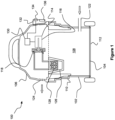
- Figure 1 shows a side view of a vacuum device 100 according to an example.
- the vacuum device 100 is a vacuum device 100 arranged to be used on a construction site or in a tool shop e.g. a workshop vacuum device 100.
- the vacuum device 100 is a wet-dry vacuum cleaner.
- the vacuum device 100 is any other type of vacuum device 100 such as an upright vacuum cleaner, a stickvac, a handheld vacuum cleaner, a canister vacuum cleaner, or any other type of vacuum cleaner.
- the vacuum device 100 comprises a housing 102.
- the housing 102 comprises a lower housing portion 104 and an upper lid portion 106.
- the upper lid portion 106 is securable to the lower housing portion 104 with one or more latches (not shown).
- the upper lid portion 106 can be separated from the lower housing portion 104 to empty the vacuum device 100.
- the upper lid portion 106 can be removed from the lower housing portion 104 to conduct maintenance and cleaning of the vacuum device 100.
- the lower housing portion 104 comprises a collection chamber 108 for receiving, dirt, debris and / or liquid entrained in the dirty airflow.
- the collection chamber 108 may possess any dimensions and shapes suitable for receiving debris and / or liquid.
- the lower housing portion 104 and the collection chamber 108 are generally cylindrical.
- the collection chamber 108 may possesses a generally frustoconical shape.
- the collection chamber 108 may include one or more curved side walls 110.
- the vacuum device 100 can comprise any suitable shape.
- the vacuum device 100 can be an elongate shape whereby the length of the housing 102 is greater than the height of the housing 102.
- an interior surface of a base 112 of the lower housing portion 104 and the collection chamber 108 may be generally concave.
- the bottom of the lower housing portion 104 and the collection chamber 108 may possess a slightly upward curve to, e.g., prevent the collection chamber 108 from sagging when filled with a predetermined amount of debris and / or liquid.
- the vacuum device 100 comprises a motor-fan assembly 114 mounted within the housing 102.
- the motor-fan assembly 114 comprises a motor 116 and a fan 118 is mounted on a rotatable motor shaft 200 (as shown in Figure 2 ).
- the motor-fan assembly 114 is arranged to generate a negative pressure and create an airflow.
- the fan 118 is mounted directly to the rotatable motor shaft 200 of the motor 116.
- the rotatable motor shaft 200 can be coupled to a gearbox (not shown) configured to transmit rotation to a drive shaft (not shown) and the fan 118 is mounted on the drive shaft.
- the gearbox can step up or step down the rotational speed of the drive shaft with respect to the rotational speed of the rotatable motor shaft 200.
- the generated airflow air is configured to move along an airflow path between a dirty air inlet 122 and a clean air exhaust outlet 124.
- the clean air exhaust outlet 124 is a plurality of holes in the housing 102 e.g. the upper lid portion 106.
- the clean air exhaust outlet 124 can be any hole, slot, or orifice in the housing 102 to let the clean air exhaust out of the vacuum device 100.
- the collection chamber 108 is positioned along the airflow path and arranged to capture debris, dirt and / or liquid droplets entrained in the dirty airflow. The captured dirt, debris, liquid droplets etc (and other debris) collects at the bottom of the collection chamber 108.
- the upper lid portion 106 houses a motor-fan assembly 114 configured to generate an airflow.
- the motor-fan assembly 114 in some examples is electrically connected to a power source 206 (as shown in Figure 2 ).
- the power source 206 is an AC power source e.g. a mains power supply.
- the power source 206 is a DC power source e.g. a battery.
- the power source 206 is a mains power supply.
- the motor-fan assembly 114 is additionally or alternatively electrically connected to a battery (not shown).
- the vacuum device 100 comprises one or more filters 126 which is mounted to the upper lid portion 106.
- the filter 126 is positioned such that the filter 126 is positioned on the airflow path between the dirty air inlet 122 and the clean air exhaust outlet 124.
- the filter 126 is optionally removably mounted on a safety valve 128.
- the safety valve 128 is arranged to prevent liquid from overflowing form the collection chamber 108 into the upper lid portion 106 when the vacuum device 100 is operated in a "wet mode".
- the safety valve 128 is known and will not be discussed any further.
- the filter 126 is removed from the safety valve 128.
- the arrangement of the vacuum device 100 as shown in Figure 1 is with the filter 126 and the vacuum device 100 is operable in a "dry mode".
- the upper lid portion 106 comprises one or more electrical and electronic components of the vacuum device 100. Whilst Figure 1 shows the one or more electrical and electronic components mounted in the upper lid portion 106, the one or more electrical and electronic components can be mounted anywhere within the housing 102.
- the vacuum device 100 comprises a control panel 132 having one or more actuators 134 (e.g., a control knob) operable to control the operational parameters of the device.
- the control panel 132 is configured to control the power (ON/OFF) with a main ON/OFF switch (not shown) and the fan speed of the motor-fan assembly 114 with a fan control speed dial (not shown).
- the control panel 132 may optionally further include one or more power outlets 136 or other power connections (not shown). In this way, a power tool (not shown) can be connected by a power cord and receive electrical power from the vacuum device 100.
- the electrical components may be controlled via a circuit board or a controller 130 mounted in the housing 102.
- the controller 130 is mounted within the housing 102 of the motor 116 e.g. inside the motor can housing (not shown). In this way, the motor 116 and the controller 130 are a unitary component.
- the controller 130 is mounted to the interior surface of the control panel 132 on the upper lid portion 106. In some other examples, the controller 130 is mounted in any other location within the housing 102.
- the controller 130 may be implemented on hardware, firmware or software operating on one or more processors or computers. A single processor can operate the different functionalities or separate individual processors, or separate groups of processors can operate each functionality.
- Figure 2 shows a schematic diagram of the controller 130 and the vacuum device 100.
- the controller 130 is configured to control the motor-fan assembly 114 to change the torque on the rotatable motor shaft 200 and the airflow speed generated by the fan 118 as discussed hereinafter.
- the controller 130 is connected to one or more sensors configured to detect one or more operating electrical parameters of the motor 116.
- the controller 130 is connected to a voltage sensor 202 and a current sensor 204 for respectively detecting the voltage across the motor 116 and the current through the motor 116.
- the voltage sensor 202 and the current sensor 204 are mounted within the housing of the motor 116 e.g. inside the motor can housing. In this way, the motor 116 and the voltage sensor 202 and the current sensor 204 are a unitary component.
- the controller 130 is configured to receive at least one signal relating to one or more operational parameters of the motor 116 during operation of the motor-fan assembly 114 as show in step 400 of Figure 4.
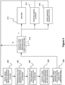
- Figure 4 shows a flow diagram of a control process implemented in the controller 130.
- the controller 130 is configured to receive a plurality of signals relating to one or more operational electrical parameters of the motor 116 during operation of the motor-fan assembly 114.
- the controller 130 determines one or more operational electrical parameters of the motor-fan assembly 114 based on the received signals as shown in step 402 of Figure 4 . For example, the controller 130 determines the voltage and the current respectively from the received signals from the voltage sensor 202 and the current sensor 204.
- the controller 130 receives a signal from the voltage sensor 202 and a signal from the current sensor 204 during operation of the motor-fan assembly 114.
- the voltage sensor 202 and the current sensor 204 periodically send the signals to the controller 130.
- the voltage sensor 202 and the current sensor 204 constantly send the signals to the controller 130.
- the voltage sensor 202 is configured to send information relating to the voltage across the motor 116 during operation to the controller 130.
- the current sensor 204 is configured to send information relating to the current through the vacuum device 100 during operation to the controller 130.
- the controller 130 is configured to determine one or more other operational parameters of the motor-fan assembly 114 as shown in step 404 in Figure 4 .
- the other operational parameters of the motor-fan assembly 114 can be any parameters of the motor-fan assembly 114 that can affect the functionality of the motor-fan assembly 114 during operation.
- the controller 130 is optionally connected to a speed sensor 208.
- the speed sensor 208 is a hall sensor configured to detect each revolution of the motor 116.
- the speed sensor 208 can be an optical sensor or any other suitable sensor configured to detect rotation of the motor 116, the rotatable motor shaft 200, or the fan 118 etc.
- the speed sensor 208 is configured to send a signal to the controller 130.
- the controller 130 is configured to determine the rotational speed of the motor 116 in dependence of the received signal from the speed sensor 208.
- the controller 130 is not connected to a speed sensor 208 and instead, the controller 130 receives information from a look-up table stored in memory (not shown) relating to the speed of the motor 116. For example, the controller 130 can receive estimated speed information based on the voltage and current signals during operation.
- the controller 130 receives a signal from the motor 116 corresponding to the number of times the rotatable motor shaft 200 rotates with respect to the poles (not shown). Similarly, the controller 130 determines the rotational speed of the rotatable motor shaft 200 based on the signal received from the motor 116. In some examples, the controller 130 determines the rotation speed of the motor shaft 200 based on the voltage, current and model of the motor 116 and the vacuum device 100. In this example, the motor 116 may be an AC induction motor. In some other examples, the rotation speed and position of the motor shaft 200 may be determined by the controller 130 via other sensorless algorithms.
- the motor 116 may be a BLDC (brushless DC) motor, an induction motor, an ASM (asynchronous motor) or any other motor which generates a back EMF.
- the rotation speed and position of the motor shaft 200 may optionally be determined based on back EMF measurements or variation of the motor induction.
- the motor 116 may be a brushed DC motor or an AC brushed motor.
- the rotational speed may be estimated based on the motor model and the measurement of the voltage and current.
- the controller 130 is configured to determine an efficiency parameter or efficiency factor ⁇ of the motor 116 as shown in step 404 of Figure 4 .
- the controller 130 is configured to determine the efficiency factor ⁇ for one or more actuating variables of the motor 116 and / or motor-fan assembly 114.
- the controller 130 is the controller 130 receives information from a look-up table stored in memory (not shown) relating to the efficiency of the motor 116. For example, the controller 130 determines the phase angle of the motor 116 during operation and receives information relating to the efficiency of the motor 116 based on the determined phase angle.
- the controller 130 is configured to determine the efficiency of the motor 116 during a calibration operation based on operational parameters of the motor 116.
- the phase angle of the motor 116 is determined by the controller 130.
- the information relating to the phase angle (° phase ) of the motor 116 is sent from the motor 116 to the controller 130.
- the vacuum device 100 is powered by an AC voltage. Since the grid voltage U grid follows a sin wave, the controller 130 must determine the phase angle of the voltage in order to determine the electrical power P elec . For example, the phase angle is the angle or the moment of the sin-wave of the voltage where the triac switches (not shown) on. The controller 130 is determines the° phase such that the controller 130 can control the power and speed of the motor 116.
- the controller 130 is configured to determine the phase angle for every half of the sine wave of the grid voltage U grid in order to determine how much power is delivered to the motor 116. In some examples, the controller 130 is configured to determine the phase angle more frequently e.g. every quarter, sixth, eighth, or tenth etc. of the sine wave of the grid voltage U grid . Furthermore, the controller 130 determines the phase angle because this affects the power of the motor 116 and in turn the operation point of the motor 116.
- the operation point of the motor 116 is specific point within the operation characteristic of the motor-fan assembly 114.
- the efficiency factor ⁇ depends on the operation point of the motor-fan assembly 114 and therefore the efficiency factor ⁇ depends indirectly on the phase angle.
- the phase angle is calculated by a motor control part (not shown) of the motor 116.
- the controller 130 can be configured to receive information relating to the phase angle during operation of the motor 116.
- the controller 130 is configured to measure and determine the phase angle.
- the vacuum device 100 optionally undergoes a calibration process.
- the one or more parameters of the vacuum device 100 are determined during the calibration process.
- An efficiency look-up table corresponding to the determined parameters of the vacuum device 100 during calibration are stored in a memory of the controller 130.
- the look-up table is stored in the memory of the controller 130 without performing a calibration process in a factory set up process.
- the controller 130 is configured to receive sensor information relating to the motor current and the motor voltage and motor speed. Based on the received motor current, motor voltage and motor speed, the controller 130 is configured to determine the efficiency of the motor by using the efficiency look-up table. Accordingly, the controller 130 is able to determine the efficiency of the motor 116 in real time or near real time.
- the motor-fan assembly 114 is powered by a DC power source 206.
- the phase angle is constant and the efficiency factor is also constant.
- controller 130 is configured to determine the operational electrical parameters of the motor-fan assembly 114 as shown in step 402 as follows.
- the mechanical power P mec is equal to the electrical power P eLec multiplied by an efficiency factor ⁇ .
- P mec ⁇ P elec
- the average electrical power P eLec is determined by the product of the current I ( i ) and voltage U(i) which are sampled discretely at time intervals i .
- the controller 130 is configured to control the frequency of sampling the current and / or the voltage. In some examples, the controller 130 receives signals from the voltage sensor 202 and the current sensor 204 a plurality of times during a half wave of the grid frequency.
- the nominal power is calculated by the controller 130 over the sinus half wave of the grid voltage.
- the grid frequency is e.g. 50Hz and comprises two half waves and the controller 130 is configured to received signals comprising measured voltage values and current values in one halve wave several times. This means that the controller 130 can determine a good estimation of the electrical power.
- the controller 130 is configured to update active power calculation by summation and averaging of the instantaneous power each half-cycle of the mains frequency.
- the number k of samples per half-wave is 5, 10, 15, 20, 25, 50 or any other suitable number of samples per half-wave needed to provide a good resolution for determining the power.
- the mechanical power P mech is determined by the torque M on the rotatable motor shaft 200 multiplied by the angular velocity ⁇ of the rotatable motor shaft 200.
- n can be determined from the speed sensor 208.
- the efficiency ⁇ may vary.
- the efficiency ⁇ may be calculated in a similar way as described above except one or more parameters of the DC power source need to be considered e.g. duty cycle.
- the controller 130 is configured to determine the efficiency factor ⁇ for one or more actuating variables of the motor 116 and / or motor-fan assembly 114.
- the one or more actuating variables may be the phase angle for an AC motor or a duty cycle for a DC brushless motor.
- the controller 130 either determines or receives a signal relating to the phase angle of the voltage across the motor 116.
- U grid is the voltage of the mains power source 206
- U ADC is the voltage across an analog to digital converter (ADC) (not shown)
- U ref is the reference voltage used by the ADC.
- R 1 and R 2 are the circuit resistances. Accordingly, U grid can be simplified to U ADC multiplied by a factor A which corresponds to the specific characteristics of the circuit of the vacuum device 100.
- the factor A can be calculated during factory setting or a calibration process of the vacuum device 100.
- I is the current through the motor 116
- I ADC is the digital value for the current
- U off is the offset voltage.
- the operational amplifier or Opamp (not shown) is configured to operate as a summing amplifier. This means the voltage over the shunt resistor is amplified with a fixed factor and fixed voltage is added to the Opamp output. Accordingly, an offset to the current is added in the circuit hardware.
- the controller 130 is configured to subsequently remove the current offset, V Op is the voltage in the Opamp, R shunt is the resistance of the shunt in the circuit. Accordingly, I can be simplified to I ADC multiplied by a factor B minus an offset factor b which corresponds to the specific characteristics of the circuit of the vacuum device 100.
- the factors B , b can be calculated during a factory setting or a calibration process of the vacuum device 100.
- the torque M can be determined by the controller 130 as shown in step 406 of Figure 4 .
- the velocity of the air v air in the vacuum device 100 can be determined from torque M as a function of M by the controller 130 as shown in step 408 of Figure 4 .
- v air f M
- the air velocity v air is a linear function of the torque M.
- the linear function varies in dependence on the operation point of the turbine and motor, and so indirect to the phase angle. The linear relationship between air velocity v air and the torque M and be determined by the controller 130 during a factory setting or a calibration procedure.
- the controller 130 can determine the air velocity v air indirectly by determining only the torque M.
- the step 408 can be carried out before operation of the vacuum device 100 in a calibration process. Accordingly, the controller 130 may save processing power by only determining the torque during operation and then inferring the air velocity v air from the predetermined functional relationship between the torque and the air velocity v air .
- Figure 3 shows a graph of airflow of a vacuum device 100 over time representing different operational scenarios of the vacuum device 100.
- Figure 3 shows three different scenarios of the vacuum device 100.
- the three difference operational scenarios 1, 2 and 3 are respectively labelled “1", “2" and “3” in circles in Figure 3 .
- Scenario 1 represents the vacuum device 100 with the motor-fan assembly 114 operating at maximum airflow but subsequently suffers a catastrophic failure.
- Figure 3 shows a maximum air velocity 300 at which the vacuum device 100 is operating.
- the maximum air velocity 300 can be the air velocity generated with the maximum operating speed of the fan 118.
- the maximum air velocity 300 can be air velocity generated at the most efficient speed of the fan 118 with respect to the other parameters of the motor-fan assembly 114 and the other parameters of the vacuum device 100.
- the vacuum device 100 is designed to operate over a minimum air velocity 302 represented by line 302.
- the minimum air velocity 302 is predetermined and corresponds to the air velocity to remove hazardous particles from a work environment.
- the predetermined minimum air velocity 302 is 20m/s.
- the minimum air velocity 302 can be adjusted by the user.
- the user can select the minimum air velocity 302 suited for a particular job.
- the minimum air velocity 302 is fixed and cannot be adjusted by the user. This means that the vacuum device 100 can be certified that the vacuum device 100 is rated to a particular standard e.g., H Class or M class.
- the controller 130 determines that an airflow parameter or the determined torque of the rotatable motor shaft 200 is below a threshold value as shown in step 410 in Figure 4 . In some examples, the controller 130 determines when the airflow parameter is above or below the minimum air velocity 302.
- the controller 130 determines that the vacuum device 100 is operating normally when the determined airflow velocity is between the minimum air velocity 302 and the maximum air velocity 300. For example, the controller 130 determines that the air velocity is at the maximum air velocity 300 at the time T1. In this case, the controller 130 takes no action based on the determined airflow velocity. Accordingly, the method returns to step 400 and controller 130 continues determining the airflow velocity.
- the vacuum device 100 ceases to operate normally.
- the fan 118 breaks, or the dirty air inlet 122 becomes blocked.
- the determined airflow will suddenly decrease and reduce to zero or below the minimum air velocity 302 at time T2. Accordingly, when the controller 130 determines that the air velocity has fallen below the minimum air velocity 302 in step 410, the controller 130 can take one or more actions.
- the controller 130 can issue an alert to the user as shown in step 412 Figure 4 .
- the controller 130 can display the alert in the form of a visual signal such as an LED (not shown) indicating operational status on the vacuum device 100.
- the controller 130 can issue a display message (not shown) on the control panel 132.
- the controller 130 can send a signal to a loudspeaker to issue an audible warning. In this way, the user can receive information warning that the vacuum device 100 is not generating sufficient air velocity to remove hazardous particles from the workplace. Once the user receives the alert, the user can perform maintenance on the vacuum device 100 to clear the alert.
- the controller 130 is configured to determine the rate of change of the air velocity.
- the controller 130 can determine the type of operating issue with the vacuum device 100 depending on the how the air velocity changes over time. For example, in scenario 1, the controller 130 is able to determine that there is a blockage or a fan 118 failure because the air velocity drops rapidly below the minimum air velocity 302 and possibly to 0 m/s.
- the filter 126 becomes blocked over time.
- the controller 130 instructs the motor-fan assembly 114 to spin up to a fan speed for generating the maximum air velocity 300. Thereafter, the vacuum device 100 operates normally. However, after a period of time, the air velocity gradually decreases. Accordingly, the controller 130 determines that the air velocity at time T4 is below the maximum air velocity 300 despite instructing the motor-fan assembly 114 to generate the maximum air velocity 300. The controller 130 then determines that the air velocity drops below the minimum air velocity 302 at time T5.
- the controller 130 can then issue an alert as previously discussed in reference to step 412. Since the controller 130 has determined the air velocity has been gradually decreasing over time e.g., at T4 and T5, the controller 130 determines that the filter 126 has become clogged due to a buildup of dirt and debris during operation of the vacuum device 100.
- the controller 130 can include information about the type of error with the vacuum device 100 in the alert in step 412. Additionally, or alternatively, the controller 130 can initiate a filter cleaning procedure based on the determination that the filter 126 has become clogged.
- the controller 130 sends a control instruction to the motor-fan assembly 114 to reverse the airflow through the filter 126 as shown in step 414 in Figure 4 .
- the reversed airflow can dislodge the dirt and debris on the filter 126.
- the air velocity will then return to the maximum air velocity 300 and the vacuum device 100 can return to normal operation.
- This automatic filter cleaning process is advantageous because the filter cleaning process only occurs when the filter 126 is blocked. This means that the vacuum device 100 does not need to carry out a filter cleaning process based on a timer expiring. Accordingly, the user does not experience as much disruption when using the vacuum device 100.
- the motor-fan assembly 114 is generating an airflow at an air velocity which is above the maximum air velocity 300.
- the controller 130 sends a control signal to the motor-fan assembly 114 to spin the motor-fan assembly 114 at the maximum air velocity 300.
- the motor-fan assembly 114 is generating an airflow at an air velocity which is above the maximum air velocity 300.
- the controller 130 determines that the air velocity is above maximum air velocity 300 and sends a control instruction to reduce the speed of the motor-fan assembly 114 as shown at time T7 and step 416 as shown in Figure 4 .
- the controller 130 can determine that the air velocity is below minimum air velocity 302 and sends a control instruction to increase the speed of the motor-fan assembly 114. For example, there is an increase amount of dirt or debris in the air and therefore there is more load on the fan 118.
- the controller 130 can perform a dynamic control on the motor-fan assembly 114 speed to control the air velocity within a predetermined range e.g., between the maximum air velocity 300 and the minimum air velocity 302.
- the controller 130 can perform a dynamic control on the motor-fan assembly 114 speed to control the air velocity about a predetermined value e.g., the maximum air velocity 300.
- the various examples of the disclosure may be implemented in hardware or special purpose circuits, software, logic, or any combination thereof.
- some aspects may be implemented in hardware, while other aspects may be implemented in firmware or software which may be executed by a controller, microprocessor, or other computing device, although the disclosure is not limited thereto.
- firmware or software which may be executed by a controller, microprocessor, or other computing device, although the disclosure is not limited thereto.
- While various aspects of the disclosure may be illustrated and described as block diagrams, flow charts, or using some other pictorial representation, it is well understood that these blocks, apparatus, systems, techniques, or methods described herein may be implemented in, as non-limiting examples, hardware, software, firmware, special purpose circuits or logic, general purpose hardware or controller or other computing devices, or some combination thereof.
- the examples of this disclosure may be implemented by computer software executable by a data processor, such as in the processor entity, or by hardware, or by a combination of software and hardware.
- the data processing may be provided by means of one or more data processors.
- any blocks of the logic flow as in the Figures may represent program steps, or interconnected logic circuits, blocks and functions, or a combination of program steps and logic circuits, blocks, and functions.
- Appropriately adapted computer program code product may be used for implementing the examples, when loaded to a computer.
- the program code product for providing the operation may be stored on and provided by means of a carrier medium such as a carrier disc, card, or tape.
- the controller in some examples may comprise a memory.
- the memory may be of any type suitable to the local technical environment and may be implemented using any suitable data storage technology, such as semiconductor based memory devices, magnetic memory devices and systems, optical memory devices and systems, fixed memory, and removable memory.
- the data processors may be of any type suitable to the local technical environment, and may include one or more of general purpose computers, special purpose computers, microprocessors, digital signal processors (DSPs) and processors based on multi core processor architecture, as non-limiting examples.
- Some examples of the disclosure may be implemented as a chipset, in other words a series of integrated circuits communicating among each other.
- the chipset may comprise microprocessors arranged to run code, application specific integrated circuits (ASICs), or programmable digital signal processors for performing the operations described above.
- ASICs application specific integrated circuits
- programmable digital signal processors for performing the operations described above.
- Examples of the disclosures may be practiced in various components such as integrated circuit modules.
- the design of integrated circuits can be by and large a highly automated process.
- Complex and powerful software tools may be available for converting a logic level design into a semiconductor circuit design ready to be etched and formed on a semiconductor substrate.
Landscapes
- Engineering & Computer Science (AREA)
- Mechanical Engineering (AREA)
- Control Of Electric Motors In General (AREA)
- Control Of Positive-Displacement Air Blowers (AREA)
Abstract
Description
- The present disclosure relates to a vacuum cleaner, controller, and a method therefor. In particular, the present disclosure relates to vacuum cleaner, controller, and a method for determining airflow in the vacuum cleaner.
- Vacuum cleaners are often used in workshops to make sure waste particles are not dispersed into the air or distributed over the surfaces of the workshops. Some vacuum cleaners are rated to maintain a specific airflow velocity in order to remove potentially harmful particles for the user.
- For example, an H class vacuum cleaner is rated for collection of dust hazardous to health and the airflow velocity is maintained above 20 m/s in the suction hose.
- This means that the vacuum cleaner must detect the airflow velocity to ensure it is compliant with the relevant safety regulations. One known method of determining the air velocity in a vacuum cleaner is with differential pressure sensors. However, pressure sensors are expensive, sensitive to shocks, and susceptible to failure. This means that the vacuum cleaner must be repaired before being safe to use in a hazardous environment.
- Examples of the present disclosure aim to address the aforementioned problems.
- According to an aspect of the present disclosure there is a method of determining an airflow parameter in a vacuum cleaner comprising a motor-fan assembly comprising: receiving one or more signals relating to one or more operational parameters of the motor; determining a torque of a rotatable shaft of the motor based on the one or more operational parameters; and determining an airflow parameter based on the determined torque of the rotatable shaft of the motor.
- Optionally, the receiving one or more signals relating to one or more operational parameters comprises receiving one or more signals relating to one or more operational electrical parameters of the motor-fan assembly during operation of the motor-fan assembly.
- Optionally, the receiving one or more signals comprises receiving a signal relating to the voltage.
- Optionally, the receiving one or more signals comprises receiving a signal relating to the current.
- Optionally, the method comprises determining the power based on the received signals relating to the current and the voltage.
- Optionally, the determining the torque is based on the determined power.
- Optionally, the method comprises determining the rotational speed of the motor.
- Optionally, the determining the speed is based on a received signal from a motor rotational speed sensor and / or the motor.
- Optionally, the method comprises determining one or more other operational parameters of the motor-fan assembly in dependence of the received one or more signals and / or stored parameter information of the motor-fan assembly.
- Optionally, the determining one or more other operational parameters of the motor-fan assembly comprises determining an efficiency of the motor-fan assembly.
- Optionally, the determining the efficiency of the motor-fan assembly comprises receiving a stored efficiency parameter for the motor-fan assembly.
- Optionally, the determining the efficiency of the motor-fan assembly comprises determining the efficiency parameter for one or more actuating variables of the motor-fan assembly.
- Optionally, the determining the airflow parameter is based on the determined torque and the determined efficiency of the motor-fan assembly.
- Optionally, the functional relationship between the airflow and the torque is predetermined.
- Optionally, the method comprises determining that the airflow parameter is below a first threshold value.
- Optionally, the method comprises issuing an alert to a user in dependence of the determining that the airflow parameter is below the first threshold value.
- Optionally, the method comprises initiating a filter cleaning procedure in dependence of the determining that the airflow parameter is below the first threshold value.
- Optionally, the filter cleaning procedure comprises reversing the motor-fan assembly such that the direction of airflow reverses through a filter.
- Optionally, the method comprises that the airflow parameter is above a second threshold value.
- Optionally, the method comprises modifying the operational electrical parameters to reduce the airflow flow parameter below the second threshold value.
- Optionally, the airflow parameter is air velocity.
- In another aspect of the present disclosure there is provided a vacuum cleaner comprising: a motor-fan assembly; at least one sensor for measuring one or more operational parameters of the motor during operation of the motor-fan assembly; a controller configured to receiving signals from the at least one sensors, wherein the controller is configured to: determine a torque of a rotatable shaft of the motor based on the one or more operational parameters; and determine an airflow parameter based on the determined torque of the rotatable shaft of the motor.
- In yet another aspect of the present disclosure there is provided a controller for a vacuum cleaner, the controller comprising: at least one communication port configured to receiving signals from the at least one sensors, wherein the controller is configured to: determine a torque of a rotatable shaft of the motor based on the one or more operational parameters; and determine an airflow parameter based on the determined torque of the rotatable shaft of the motor.
- In another aspect of the present disclosure there is provided a method of controlling a power tool comprising a motor comprising: receiving one or more signals relating to one or more operational parameters of the motor; determining a torque of a rotatable shaft of the motor based on the one or more operational parameters; determining that the torque of the rotatable shaft of the motor exceeds or drops below a threshold value; and issuing a control signal to the power tool in dependence of the determined torque exceeding or dropping below the threshold value. The power tool may be a rotary power tool such as a drill or hammer drill.
- Various other aspects and further examples are also described in the following detailed description and in the attached claims with reference to the accompanying drawings, in which:
-
Figure 1 shows a schematic view of a vacuum device; -
Figure 2 shows a schematic diagram of a controller and a vacuum device; -
Figure 3 shows a graph of airflow of a vacuum device over time representing different operational scenarios of a vacuum device; and -
Figure 4 shows a flow diagram of a control process implemented in a controller of the vacuum device. -
Figure 1 shows a side view of avacuum device 100 according to an example. In some examples, thevacuum device 100 is avacuum device 100 arranged to be used on a construction site or in a tool shop e.g. aworkshop vacuum device 100. In some examples, thevacuum device 100 is a wet-dry vacuum cleaner. However, in other examples thevacuum device 100 is any other type ofvacuum device 100 such as an upright vacuum cleaner, a stickvac, a handheld vacuum cleaner, a canister vacuum cleaner, or any other type of vacuum cleaner. - The
vacuum device 100 comprises ahousing 102. Thehousing 102 comprises alower housing portion 104 and anupper lid portion 106. Theupper lid portion 106 is securable to thelower housing portion 104 with one or more latches (not shown). Theupper lid portion 106 can be separated from thelower housing portion 104 to empty thevacuum device 100. Furthermore, theupper lid portion 106 can be removed from thelower housing portion 104 to conduct maintenance and cleaning of thevacuum device 100. - The
lower housing portion 104 comprises acollection chamber 108 for receiving, dirt, debris and / or liquid entrained in the dirty airflow. In some examples, thecollection chamber 108 may possess any dimensions and shapes suitable for receiving debris and / or liquid. - In the example as shown in
Figure 1 , thelower housing portion 104 and thecollection chamber 108 are generally cylindrical. In another example, thecollection chamber 108 may possesses a generally frustoconical shape. Additionally or alternatively, thecollection chamber 108 may include one or morecurved side walls 110. In other examples, thevacuum device 100 can comprise any suitable shape. For example, thevacuum device 100 can be an elongate shape whereby the length of thehousing 102 is greater than the height of thehousing 102. - Optionally, (although not shown in
Figure 1 ), an interior surface of abase 112 of thelower housing portion 104 and thecollection chamber 108 may be generally concave. For example, the bottom of thelower housing portion 104 and thecollection chamber 108 may possess a slightly upward curve to, e.g., prevent thecollection chamber 108 from sagging when filled with a predetermined amount of debris and / or liquid. - The
vacuum device 100 comprises a motor-fan assembly 114 mounted within thehousing 102. The motor-fan assembly 114 comprises amotor 116 and afan 118 is mounted on a rotatable motor shaft 200 (as shown inFigure 2 ). The motor-fan assembly 114 is arranged to generate a negative pressure and create an airflow. - In the examples as shown in
Figure 1 , thefan 118 is mounted directly to therotatable motor shaft 200 of themotor 116. However, in other examples, therotatable motor shaft 200 can be coupled to a gearbox (not shown) configured to transmit rotation to a drive shaft (not shown) and thefan 118 is mounted on the drive shaft. In this way, the gearbox can step up or step down the rotational speed of the drive shaft with respect to the rotational speed of therotatable motor shaft 200. - The generated airflow air is configured to move along an airflow path between a
dirty air inlet 122 and a cleanair exhaust outlet 124. In some examples, the cleanair exhaust outlet 124 is a plurality of holes in thehousing 102 e.g. theupper lid portion 106. In other examples, the cleanair exhaust outlet 124 can be any hole, slot, or orifice in thehousing 102 to let the clean air exhaust out of thevacuum device 100. Thecollection chamber 108 is positioned along the airflow path and arranged to capture debris, dirt and / or liquid droplets entrained in the dirty airflow. The captured dirt, debris, liquid droplets etc (and other debris) collects at the bottom of thecollection chamber 108. - As shown in
Figure 1 , theupper lid portion 106 houses a motor-fan assembly 114 configured to generate an airflow. The motor-fan assembly 114 in some examples is electrically connected to a power source 206 (as shown inFigure 2 ). In some examples, thepower source 206 is an AC power source e.g. a mains power supply. In some other examples thepower source 206 is a DC power source e.g. a battery. In some examples, thepower source 206 is a mains power supply. In some examples, the motor-fan assembly 114 is additionally or alternatively electrically connected to a battery (not shown). - In some examples, the
vacuum device 100 comprises one ormore filters 126 which is mounted to theupper lid portion 106. Thefilter 126 is positioned such that thefilter 126 is positioned on the airflow path between thedirty air inlet 122 and the cleanair exhaust outlet 124. - In some examples, the
filter 126 is optionally removably mounted on asafety valve 128. Thesafety valve 128 is arranged to prevent liquid from overflowing form thecollection chamber 108 into theupper lid portion 106 when thevacuum device 100 is operated in a "wet mode". Thesafety valve 128 is known and will not be discussed any further. In order to prepare the wet-dry vacuum device 100 for wet mode operation, thefilter 126 is removed from thesafety valve 128. The arrangement of thevacuum device 100 as shown inFigure 1 is with thefilter 126 and thevacuum device 100 is operable in a "dry mode". - Referring back to
Figure 1 again, theupper lid portion 106 comprises one or more electrical and electronic components of thevacuum device 100. WhilstFigure 1 shows the one or more electrical and electronic components mounted in theupper lid portion 106, the one or more electrical and electronic components can be mounted anywhere within thehousing 102. - In some examples, the
vacuum device 100 comprises acontrol panel 132 having one or more actuators 134 (e.g., a control knob) operable to control the operational parameters of the device. For example, thecontrol panel 132 is configured to control the power (ON/OFF) with a main ON/OFF switch (not shown) and the fan speed of the motor-fan assembly 114 with a fan control speed dial (not shown). Thecontrol panel 132 may optionally further include one ormore power outlets 136 or other power connections (not shown). In this way, a power tool (not shown) can be connected by a power cord and receive electrical power from thevacuum device 100. The electrical components may be controlled via a circuit board or acontroller 130 mounted in thehousing 102. - In another example, the
controller 130 is mounted within thehousing 102 of themotor 116 e.g. inside the motor can housing (not shown). In this way, themotor 116 and thecontroller 130 are a unitary component. - In some other examples, the
controller 130 is mounted to the interior surface of thecontrol panel 132 on theupper lid portion 106. In some other examples, thecontroller 130 is mounted in any other location within thehousing 102. Thecontroller 130 may be implemented on hardware, firmware or software operating on one or more processors or computers. A single processor can operate the different functionalities or separate individual processors, or separate groups of processors can operate each functionality. - Turning to
Figure 2 , thecontroller 130 will be discussed in further detail.Figure 2 shows a schematic diagram of thecontroller 130 and thevacuum device 100. - The
controller 130 is configured to control the motor-fan assembly 114 to change the torque on therotatable motor shaft 200 and the airflow speed generated by thefan 118 as discussed hereinafter. - The
controller 130 is connected to one or more sensors configured to detect one or more operating electrical parameters of themotor 116. In some examples, thecontroller 130 is connected to avoltage sensor 202 and acurrent sensor 204 for respectively detecting the voltage across themotor 116 and the current through themotor 116. In some examples, thevoltage sensor 202 and thecurrent sensor 204 are mounted within the housing of themotor 116 e.g. inside the motor can housing. In this way, themotor 116 and thevoltage sensor 202 and thecurrent sensor 204 are a unitary component. - The
controller 130 is configured to receive at least one signal relating to one or more operational parameters of themotor 116 during operation of the motor-fan assembly 114 as show instep 400 ofFigure 4. Figure 4 shows a flow diagram of a control process implemented in thecontroller 130. - In some examples, the
controller 130 is configured to receive a plurality of signals relating to one or more operational electrical parameters of themotor 116 during operation of the motor-fan assembly 114. - The
controller 130 then determines one or more operational electrical parameters of the motor-fan assembly 114 based on the received signals as shown instep 402 ofFigure 4 . For example, thecontroller 130 determines the voltage and the current respectively from the received signals from thevoltage sensor 202 and thecurrent sensor 204. - In this way, the
controller 130 receives a signal from thevoltage sensor 202 and a signal from thecurrent sensor 204 during operation of the motor-fan assembly 114. In some examples, thevoltage sensor 202 and thecurrent sensor 204 periodically send the signals to thecontroller 130. In other examples, thevoltage sensor 202 and thecurrent sensor 204 constantly send the signals to thecontroller 130. Thevoltage sensor 202 is configured to send information relating to the voltage across themotor 116 during operation to thecontroller 130. Thecurrent sensor 204 is configured to send information relating to the current through thevacuum device 100 during operation to thecontroller 130. - In some examples, the
controller 130 is configured to determine one or more other operational parameters of the motor-fan assembly 114 as shown instep 404 inFigure 4 . The other operational parameters of the motor-fan assembly 114 can be any parameters of the motor-fan assembly 114 that can affect the functionality of the motor-fan assembly 114 during operation. - In some examples, the
controller 130 is optionally connected to aspeed sensor 208. In some examples thespeed sensor 208 is a hall sensor configured to detect each revolution of themotor 116. In some alternative examples, thespeed sensor 208 can be an optical sensor or any other suitable sensor configured to detect rotation of themotor 116, therotatable motor shaft 200, or thefan 118 etc. Thespeed sensor 208 is configured to send a signal to thecontroller 130. Thecontroller 130 is configured to determine the rotational speed of themotor 116 in dependence of the received signal from thespeed sensor 208. - In some examples, the
controller 130 is not connected to aspeed sensor 208 and instead, thecontroller 130 receives information from a look-up table stored in memory (not shown) relating to the speed of themotor 116. For example, thecontroller 130 can receive estimated speed information based on the voltage and current signals during operation. - Alternatively the
controller 130 receives a signal from themotor 116 corresponding to the number of times therotatable motor shaft 200 rotates with respect to the poles (not shown). Similarly, thecontroller 130 determines the rotational speed of therotatable motor shaft 200 based on the signal received from themotor 116. In some examples, thecontroller 130 determines the rotation speed of themotor shaft 200 based on the voltage, current and model of themotor 116 and thevacuum device 100. In this example, themotor 116 may be an AC induction motor. In some other examples, the rotation speed and position of themotor shaft 200 may be determined by thecontroller 130 via other sensorless algorithms. - For example, the
motor 116 may be a BLDC (brushless DC) motor, an induction motor, an ASM (asynchronous motor) or any other motor which generates a back EMF. The rotation speed and position of themotor shaft 200 may optionally be determined based on back EMF measurements or variation of the motor induction. - Alternatively in some other examples the
motor 116 may be a brushed DC motor or an AC brushed motor. The rotational speed may be estimated based on the motor model and the measurement of the voltage and current. - In some examples, the
controller 130 is configured to determine an efficiency parameter or efficiency factor µ of themotor 116 as shown instep 404 ofFigure 4 . Thecontroller 130 is configured to determine the efficiency factor µ for one or more actuating variables of themotor 116 and / or motor-fan assembly 114. - The
controller 130 is thecontroller 130 receives information from a look-up table stored in memory (not shown) relating to the efficiency of themotor 116. For example, thecontroller 130 determines the phase angle of themotor 116 during operation and receives information relating to the efficiency of themotor 116 based on the determined phase angle. - Alternatively, the
controller 130 is configured to determine the efficiency of themotor 116 during a calibration operation based on operational parameters of themotor 116. In some examples, the phase angle of themotor 116 is determined by thecontroller 130. Alternatively, the information relating to the phase angle (°phase ) of themotor 116 is sent from themotor 116 to thecontroller 130. - In some examples, the
vacuum device 100 is powered by an AC voltage. Since the grid voltage Ugrid follows a sin wave, thecontroller 130 must determine the phase angle of the voltage in order to determine the electrical power Pelec . For example, the phase angle is the angle or the moment of the sin-wave of the voltage where the triac switches (not shown) on. Thecontroller 130 is determines the°phase such that thecontroller 130 can control the power and speed of themotor 116. - The
controller 130 is configured to determine the phase angle for every half of the sine wave of the grid voltage Ugrid in order to determine how much power is delivered to themotor 116. In some examples, thecontroller 130 is configured to determine the phase angle more frequently e.g. every quarter, sixth, eighth, or tenth etc. of the sine wave of the grid voltage Ugrid. Furthermore, thecontroller 130 determines the phase angle because this affects the power of themotor 116 and in turn the operation point of themotor 116. - The operation point of the
motor 116 is specific point within the operation characteristic of the motor-fan assembly 114. - The efficiency factor µ depends on the operation point of the motor-
fan assembly 114 and therefore the efficiency factor µ depends indirectly on the phase angle. In some examples, the phase angle is calculated by a motor control part (not shown) of themotor 116. In this way, thecontroller 130 can be configured to receive information relating to the phase angle during operation of themotor 116. In some other examples, thecontroller 130 is configured to measure and determine the phase angle. - In some examples, the
vacuum device 100 optionally undergoes a calibration process. The one or more parameters of thevacuum device 100 are determined during the calibration process. An efficiency look-up table corresponding to the determined parameters of thevacuum device 100 during calibration are stored in a memory of thecontroller 130. Alternatively, the look-up table is stored in the memory of thecontroller 130 without performing a calibration process in a factory set up process. - The
controller 130 is configured to receive sensor information relating to the motor current and the motor voltage and motor speed. Based on the received motor current, motor voltage and motor speed, thecontroller 130 is configured to determine the efficiency of the motor by using the efficiency look-up table. Accordingly, thecontroller 130 is able to determine the efficiency of themotor 116 in real time or near real time. - In contrast, in some examples the motor-
fan assembly 114 is powered by aDC power source 206. In this case, the phase angle is constant and the efficiency factor is also constant. - In some examples, the
controller 130 is configured to determine the operational electrical parameters of the motor-fan assembly 114 as shown instep 402 as follows. - The mechanical power Pmec is equal to the electrical power PeLec multiplied by an efficiency factor µ.

- The average electrical power PeLec is determined by the product of the current I(i) and voltage U(i) which are sampled discretely at time intervals i. The
controller 130 is configured to control the frequency of sampling the current and / or the voltage. In some examples, thecontroller 130 receives signals from thevoltage sensor 202 and the current sensor 204 a plurality of times during a half wave of the grid frequency. - In some examples, the nominal power is calculated by the
controller 130 over the sinus half wave of the grid voltage. The grid frequency is e.g. 50Hz and comprises two half waves and thecontroller 130 is configured to received signals comprising measured voltage values and current values in one halve wave several times. This means that thecontroller 130 can determine a good estimation of the electrical power. With an adequate number k of samples per half-wave thecontroller 130 is configured to update active power calculation by summation and averaging of the instantaneous power each half-cycle of the mains frequency. In some examples, the number k of samples per half-wave is 5, 10, 15, 20, 25, 50 or any other suitable number of samples per half-wave needed to provide a good resolution for determining the power.
- The mechanical power Pmech is determined by the torque M on the
rotatable motor shaft 200 multiplied by the angular velocity ω of therotatable motor shaft 200. As mentioned above, n can be determined from thespeed sensor 208.
- Accordingly, when equation [1] is combined with equation [3], for an AC power source 206:

- In contrast, if a
DC power source 206 is alternatively used, then the efficiency µ may vary. The efficiency µ may be calculated in a similar way as described above except one or more parameters of the DC power source need to be considered e.g. duty cycle. For example, the following equation may be used:
- As mentioned above, the
controller 130 is configured to determine the efficiency factor µ for one or more actuating variables of themotor 116 and / or motor-fan assembly 114. The one or more actuating variables may be the phase angle for an AC motor or a duty cycle for a DC brushless motor. - As mentioned above, the
controller 130 either determines or receives a signal relating to the phase angle of the voltage across themotor 116.
- Where Ugrid is the voltage of the
mains power source 206, UADC is the voltage across an analog to digital converter (ADC) (not shown) and Uref is the reference voltage used by the ADC. R 1 and R 2 are the circuit resistances. Accordingly, Ugrid can be simplified to UADC multiplied by a factor A which corresponds to the specific characteristics of the circuit of thevacuum device 100. The factor A can be calculated during factory setting or a calibration process of thevacuum device 100.
- Where I is the current through the
motor 116, and IADC is the digital value for the current. - Uoff is the offset voltage. The operational amplifier or Opamp (not shown) is configured to operate as a summing amplifier. This means the voltage over the shunt resistor is amplified with a fixed factor and fixed voltage is added to the Opamp output. Accordingly, an offset to the current is added in the circuit hardware. The
controller 130 is configured to subsequently remove the current offset, VOp is the voltage in the Opamp, Rshunt is the resistance of the shunt in the circuit. Accordingly, I can be simplified to IADC multiplied by a factor B minus an offset factor b which corresponds to the specific characteristics of the circuit of thevacuum device 100. The factors B , b can be calculated during a factory setting or a calibration process of thevacuum device 100. - Rearranging [2] with [5] and [6] the following can be calculated by the
controller 130.
- In this way using [7] and [4], the torque M can be determined by the
controller 130 as shown instep 406 ofFigure 4 . In some examples, thecontroller 130 is arranged to use the following equation for the AC power source 206:
- Alternatively, the
controller 130 can use the following equation for the DC power source 206:
- The velocity of the air vair in the
vacuum device 100, can be determined from torque M as a function of M by thecontroller 130 as shown instep 408 ofFigure 4 .
- In some examples, the air velocity vair is a linear function of the torque M. In some examples, the linear function varies in dependence on the operation point of the turbine and motor, and so indirect to the phase angle. The linear relationship between air velocity vair and the torque M and be determined by the
controller 130 during a factory setting or a calibration procedure. - Accordingly, in some examples, since the functional relationship between the torque and the air velocity vair can be predetermined e.g., in a calibration process, the
controller 130 can determine the air velocity vair indirectly by determining only the torque M. In other words, thestep 408 can be carried out before operation of thevacuum device 100 in a calibration process. Accordingly, thecontroller 130 may save processing power by only determining the torque during operation and then inferring the air velocity vair from the predetermined functional relationship between the torque and the air velocity vair. - Turning now to
Figure 3 , further operation of thevacuum device 100 and thecontroller 130 will now be discussed.Figure 3 shows a graph of airflow of avacuum device 100 over time representing different operational scenarios of thevacuum device 100. -
Figure 3 shows three different scenarios of thevacuum device 100. The three differenceoperational scenarios Figure 3 . - Scenario 1 represents the
vacuum device 100 with the motor-fan assembly 114 operating at maximum airflow but subsequently suffers a catastrophic failure.Figure 3 shows amaximum air velocity 300 at which thevacuum device 100 is operating. In some examples, themaximum air velocity 300 can be the air velocity generated with the maximum operating speed of thefan 118. Alternatively, themaximum air velocity 300 can be air velocity generated at the most efficient speed of thefan 118 with respect to the other parameters of the motor-fan assembly 114 and the other parameters of thevacuum device 100. - In some examples, the
vacuum device 100 is designed to operate over aminimum air velocity 302 represented byline 302. In some examples, theminimum air velocity 302 is predetermined and corresponds to the air velocity to remove hazardous particles from a work environment. In some examples, the predeterminedminimum air velocity 302 is 20m/s. - In some examples, the
minimum air velocity 302 can be adjusted by the user. For example, the user can select theminimum air velocity 302 suited for a particular job. Alternatively, theminimum air velocity 302 is fixed and cannot be adjusted by the user. This means that thevacuum device 100 can be certified that thevacuum device 100 is rated to a particular standard e.g., H Class or M class. - In some examples, the
controller 130 determines that an airflow parameter or the determined torque of therotatable motor shaft 200 is below a threshold value as shown instep 410 inFigure 4 . In some examples, thecontroller 130 determines when the airflow parameter is above or below theminimum air velocity 302. - In some examples, the
controller 130 determines that thevacuum device 100 is operating normally when the determined airflow velocity is between theminimum air velocity 302 and themaximum air velocity 300. For example, thecontroller 130 determines that the air velocity is at themaximum air velocity 300 at the time T1. In this case, thecontroller 130 takes no action based on the determined airflow velocity. Accordingly, the method returns to step 400 andcontroller 130 continues determining the airflow velocity. - However, in some examples the
vacuum device 100 ceases to operate normally. For example, in scenario 1 thefan 118 breaks, or thedirty air inlet 122 becomes blocked. In this case, the determined airflow will suddenly decrease and reduce to zero or below theminimum air velocity 302 at time T2. Accordingly, when thecontroller 130 determines that the air velocity has fallen below theminimum air velocity 302 instep 410, thecontroller 130 can take one or more actions. - In some examples, the
controller 130 can issue an alert to the user as shown instep 412Figure 4 . Thecontroller 130 can display the alert in the form of a visual signal such as an LED (not shown) indicating operational status on thevacuum device 100. Alternatively, thecontroller 130 can issue a display message (not shown) on thecontrol panel 132. Additionally, or alternatively, thecontroller 130 can send a signal to a loudspeaker to issue an audible warning. In this way, the user can receive information warning that thevacuum device 100 is not generating sufficient air velocity to remove hazardous particles from the workplace. Once the user receives the alert, the user can perform maintenance on thevacuum device 100 to clear the alert. - In some examples, the
controller 130 is configured to determine the rate of change of the air velocity. Thecontroller 130 can determine the type of operating issue with thevacuum device 100 depending on the how the air velocity changes over time. For example, in scenario 1, thecontroller 130 is able to determine that there is a blockage or afan 118 failure because the air velocity drops rapidly below theminimum air velocity 302 and possibly to 0 m/s. - In
scenario 2, thefilter 126 becomes blocked over time. At time T3 thecontroller 130 instructs the motor-fan assembly 114 to spin up to a fan speed for generating themaximum air velocity 300. Thereafter, thevacuum device 100 operates normally. However, after a period of time, the air velocity gradually decreases. Accordingly, thecontroller 130 determines that the air velocity at time T4 is below themaximum air velocity 300 despite instructing the motor-fan assembly 114 to generate themaximum air velocity 300. Thecontroller 130 then determines that the air velocity drops below theminimum air velocity 302 at time T5. - The
controller 130 can then issue an alert as previously discussed in reference to step 412. Since thecontroller 130 has determined the air velocity has been gradually decreasing over time e.g., at T4 and T5, thecontroller 130 determines that thefilter 126 has become clogged due to a buildup of dirt and debris during operation of thevacuum device 100. - Accordingly, the
controller 130 can include information about the type of error with thevacuum device 100 in the alert instep 412. Additionally, or alternatively, thecontroller 130 can initiate a filter cleaning procedure based on the determination that thefilter 126 has become clogged. - In some examples, the
controller 130 sends a control instruction to the motor-fan assembly 114 to reverse the airflow through thefilter 126 as shown instep 414 inFigure 4 . The reversed airflow can dislodge the dirt and debris on thefilter 126. The air velocity will then return to themaximum air velocity 300 and thevacuum device 100 can return to normal operation. This automatic filter cleaning process is advantageous because the filter cleaning process only occurs when thefilter 126 is blocked. This means that thevacuum device 100 does not need to carry out a filter cleaning process based on a timer expiring. Accordingly, the user does not experience as much disruption when using thevacuum device 100. - In
scenario 3, the motor-fan assembly 114 is generating an airflow at an air velocity which is above themaximum air velocity 300. At time T6, thecontroller 130 sends a control signal to the motor-fan assembly 114 to spin the motor-fan assembly 114 at themaximum air velocity 300. However, at that time there is not much dirt or debris in the air and therefore there is less load on thefan 118. This means that the motor-fan assembly 114 is generating an airflow at an air velocity which is above themaximum air velocity 300. Thecontroller 130 determines that the air velocity is abovemaximum air velocity 300 and sends a control instruction to reduce the speed of the motor-fan assembly 114 as shown at time T7 and step 416 as shown inFigure 4 . Similarly, thecontroller 130 can determine that the air velocity is belowminimum air velocity 302 and sends a control instruction to increase the speed of the motor-fan assembly 114. For example, there is an increase amount of dirt or debris in the air and therefore there is more load on thefan 118. - In this way, the
controller 130 can perform a dynamic control on the motor-fan assembly 114 speed to control the air velocity within a predetermined range e.g., between themaximum air velocity 300 and theminimum air velocity 302. Alternatively, thecontroller 130 can perform a dynamic control on the motor-fan assembly 114 speed to control the air velocity about a predetermined value e.g., themaximum air velocity 300. - In general, the various examples of the disclosure may be implemented in hardware or special purpose circuits, software, logic, or any combination thereof. For example, some aspects may be implemented in hardware, while other aspects may be implemented in firmware or software which may be executed by a controller, microprocessor, or other computing device, although the disclosure is not limited thereto. While various aspects of the disclosure may be illustrated and described as block diagrams, flow charts, or using some other pictorial representation, it is well understood that these blocks, apparatus, systems, techniques, or methods described herein may be implemented in, as non-limiting examples, hardware, software, firmware, special purpose circuits or logic, general purpose hardware or controller or other computing devices, or some combination thereof.
- The examples of this disclosure may be implemented by computer software executable by a data processor, such as in the processor entity, or by hardware, or by a combination of software and hardware. The data processing may be provided by means of one or more data processors. Further in this regard it should be noted that any blocks of the logic flow as in the Figures may represent program steps, or interconnected logic circuits, blocks and functions, or a combination of program steps and logic circuits, blocks, and functions.
- Appropriately adapted computer program code product may be used for implementing the examples, when loaded to a computer. The program code product for providing the operation may be stored on and provided by means of a carrier medium such as a carrier disc, card, or tape.
- The controller in some examples may comprise a memory. The memory may be of any type suitable to the local technical environment and may be implemented using any suitable data storage technology, such as semiconductor based memory devices, magnetic memory devices and systems, optical memory devices and systems, fixed memory, and removable memory. The data processors may be of any type suitable to the local technical environment, and may include one or more of general purpose computers, special purpose computers, microprocessors, digital signal processors (DSPs) and processors based on multi core processor architecture, as non-limiting examples.
- Some examples of the disclosure may be implemented as a chipset, in other words a series of integrated circuits communicating among each other. The chipset may comprise microprocessors arranged to run code, application specific integrated circuits (ASICs), or programmable digital signal processors for performing the operations described above.
- Examples of the disclosures may be practiced in various components such as integrated circuit modules. The design of integrated circuits can be by and large a highly automated process. Complex and powerful software tools may be available for converting a logic level design into a semiconductor circuit design ready to be etched and formed on a semiconductor substrate.
- It is noted herein that while the above describes exemplifying examples of the disclosure, there are several variations and modifications which may be made to the disclosed solution without departing from the scope of the present disclosure as defined in the appended claims. In another example, two or more examples are combined. Features of one example can be combined with features of other examples.
Claims (17)
- A method of determining an airflow parameter in a vacuum cleaner comprising a motor-fan assembly comprising:receiving one or more signals relating to one or more operational parameters of the motor;determining a torque of a rotatable shaft of the motor based on the one or more operational parameters; anddetermining an airflow parameter based on the determined torque of the rotatable shaft of the motor.
- A method according to claim 1 wherein the receiving one or more signals relating to one or more operational parameters comprises receiving one or more signals relating to one or more operational electrical parameters of the motor-fan assembly during operation of the motor-fan assembly.
- A method according to claim 2 wherein the receiving one or more signals comprises receiving a signal relating to the voltage or the current.
- A method according to claim 3 wherein the method comprises determining the power based on the received signals relating to the current and the voltage.
- A method according to 4 wherein the determining the torque is based on the determined power.
- A method according to any of the preceding claims wherein the method comprises determining the rotational speed of the motor.
- A method according to claim 6 wherein the determining the speed is based on a received signal from a motor rotational speed sensor and / or the motor.
- A method according any of the preceding claims wherein the method comprises determining one or more other operational parameters of the motor-fan assembly in dependence of the received one or more signals and / or stored parameter information of the motor-fan assembly.
- A method according claim 8 wherein the determining one or more other operational parameters of the motor-fan assembly comprises determining an efficiency of the motor-fan assembly.
- A method according to claim 9 wherein the determining the efficiency of the motor-fan assembly comprises receiving a stored efficiency parameter for the motor-fan assembly.
- A method according to claim 10 wherein the determining the efficiency of the motor-fan assembly comprises determining the efficiency parameter for one or more actuating variables of the motor-fan assembly.
- A method according to any of claims 9 to 11 wherein the determining the airflow parameter is based on the determined torque and the determined efficiency of the motor-fan assembly.
- A method according to claim 12 wherein the functional relationship between the airflow and the torque is predetermined.
- A method according to any of the preceding claims wherein the method comprises determining that the airflow parameter is below a first threshold value.
- A method comprising the method according to claim 14 and further comprising the step of:issuing an alert to a user in dependence of determining that the airflow parameter is below the first threshold value; orinitiating a filter cleaning procedure in dependence of the determining that the airflow parameter is below the first threshold value.
- A method according to any of the preceding claims wherein the airflow parameter is air velocity.
- A vacuum cleaner comprising:a motor-fan assembly;at least one sensor for measuring one or more operational parameters of the motor during operation of the motor-fan assembly;a controller configured to receiving signals from the at least one sensors, wherein the controller is configured to:determine a torque of a rotatable shaft of the motor based on the one or more operational parameters; anddetermine an airflow parameter based on the determined torque of the rotatable shaft of the motor.
Applications Claiming Priority (1)
| Application Number | Priority Date | Filing Date | Title |
|---|---|---|---|
| GB2200157.2A GB2614558A (en) | 2022-01-07 | 2022-01-07 | A vacuum cleaner, controller, and a method therefor |
Publications (2)
| Publication Number | Publication Date |
|---|---|
| EP4209161A1 true EP4209161A1 (en) | 2023-07-12 |
| EP4209161B1 EP4209161B1 (en) | 2025-07-16 |
Family
ID=84537334
Family Applications (1)
| Application Number | Title | Priority Date | Filing Date |
|---|---|---|---|
| EP22213881.0A Active EP4209161B1 (en) | 2022-01-07 | 2022-12-15 | A vacuum cleaner, controller, and a method therefor |
Country Status (2)
| Country | Link |
|---|---|
| EP (1) | EP4209161B1 (en) |
| GB (1) | GB2614558A (en) |
Cited By (1)
| Publication number | Priority date | Publication date | Assignee | Title |
|---|---|---|---|---|
| US12465183B2 (en) | 2024-03-04 | 2025-11-11 | Sharkninja Operating Llc | Handheld surface cleaner |
Citations (3)
| Publication number | Priority date | Publication date | Assignee | Title |
|---|---|---|---|---|
| EP0969589A2 (en) * | 1998-07-02 | 2000-01-05 | Switched Reluctance Drives Limited | Cleaning apparatus and method with soft-starting |
| WO2015078672A1 (en) * | 2013-11-26 | 2015-06-04 | Koninklijke Philips N.V. | Air filter monitoring |
| EP3361625A1 (en) * | 2015-10-07 | 2018-08-15 | LG Electronics Inc. | Motor driving apparatus and home appliance comprising same |
Family Cites Families (3)
| Publication number | Priority date | Publication date | Assignee | Title |
|---|---|---|---|---|
| WO2018161018A1 (en) * | 2017-03-03 | 2018-09-07 | Tti (Macao Commercial Offshore) Limited | Vacuum cleaner including a surface cleaning head having a display |
| GB2576314A (en) * | 2018-08-13 | 2020-02-19 | Black & Decker Inc | Power tool |
| DE102018129114A1 (en) * | 2018-11-20 | 2020-05-20 | Miele & Cie. Kg | Method for operating a vacuum cleaner system and vacuum cleaner system |
-
2022
- 2022-01-07 GB GB2200157.2A patent/GB2614558A/en active Pending
- 2022-12-15 EP EP22213881.0A patent/EP4209161B1/en active Active
Patent Citations (3)
| Publication number | Priority date | Publication date | Assignee | Title |
|---|---|---|---|---|
| EP0969589A2 (en) * | 1998-07-02 | 2000-01-05 | Switched Reluctance Drives Limited | Cleaning apparatus and method with soft-starting |
| WO2015078672A1 (en) * | 2013-11-26 | 2015-06-04 | Koninklijke Philips N.V. | Air filter monitoring |
| EP3361625A1 (en) * | 2015-10-07 | 2018-08-15 | LG Electronics Inc. | Motor driving apparatus and home appliance comprising same |
Cited By (1)
| Publication number | Priority date | Publication date | Assignee | Title |
|---|---|---|---|---|
| US12465183B2 (en) | 2024-03-04 | 2025-11-11 | Sharkninja Operating Llc | Handheld surface cleaner |
Also Published As
| Publication number | Publication date |
|---|---|
| GB2614558A (en) | 2023-07-12 |
| EP4209161B1 (en) | 2025-07-16 |
Similar Documents
| Publication | Publication Date | Title |
|---|---|---|
| EP1189334B1 (en) | Inverter control circuit of motor-driven blower for electric vacuum cleaner, drive control circuit using the same, and electric vacuum cleaner using the drive control circuit | |
| AU2014255502B2 (en) | Vacuum cleaner with diagnostics | |
| AU2021287162B2 (en) | Filter arrangements for industrial dust extractors | |
| US9901233B2 (en) | Air filter monitoring | |
| CN101370416B (en) | Dust collector | |
| CN201312778Y (en) | Vacuum dust collector | |
| US20020185987A1 (en) | Drive control circuit for three-phase brushless motor, motor-driven blower and electric vacuum cleaner | |
| EP4209161B1 (en) | A vacuum cleaner, controller, and a method therefor | |
| JPH10507958A (en) | Vacuum cleaner with output control depending on operating mode of electric brush | |
| JP2001224544A (en) | Electric vacuum cleaner | |
| CN106235963B (en) | Control method and dust collection equipment | |
| CN111829033A (en) | Range hood control method and range hood system applying same | |
| SE545877C2 (en) | Filter arrangements for industrial dust extractors | |
| US20220125264A1 (en) | Vacuum Cleaner, Controller, and a Method Therefor | |
| JP3809588B2 (en) | Vacuum cleaner | |
| JP2001136780A (en) | Control circuit for electric blower and vacuum cleaner | |
| JP2007029218A (en) | Electric vacuum cleaner | |
| JP2003290101A5 (en) | ||
| KR20250121062A (en) | Method for determining the initial filter load value of an air movement device | |
| WO2023094077A1 (en) | Filter cleaning of an air treatment device | |
| JP2000069787A (en) | Electric vacuum cleaner | |
| JP5907087B2 (en) | Electric vacuum cleaner | |
| JPH10146304A (en) | Electric vacuum cleaner |
Legal Events
| Date | Code | Title | Description |
|---|---|---|---|
| PUAI | Public reference made under article 153(3) epc to a published international application that has entered the european phase |
Free format text: ORIGINAL CODE: 0009012 |
|
| STAA | Information on the status of an ep patent application or granted ep patent |
Free format text: STATUS: THE APPLICATION HAS BEEN PUBLISHED |
|
| AK | Designated contracting states |
Kind code of ref document: A1 Designated state(s): AL AT BE BG CH CY CZ DE DK EE ES FI FR GB GR HR HU IE IS IT LI LT LU LV MC ME MK MT NL NO PL PT RO RS SE SI SK SM TR |
|
| STAA | Information on the status of an ep patent application or granted ep patent |
Free format text: STATUS: REQUEST FOR EXAMINATION WAS MADE |
|
| 17P | Request for examination filed |
Effective date: 20240103 |
|
| RBV | Designated contracting states (corrected) |
Designated state(s): AL AT BE BG CH CY CZ DE DK EE ES FI FR GB GR HR HU IE IS IT LI LT LU LV MC ME MK MT NL NO PL PT RO RS SE SI SK SM TR |
|
| GRAP | Despatch of communication of intention to grant a patent |
Free format text: ORIGINAL CODE: EPIDOSNIGR1 |
|
| STAA | Information on the status of an ep patent application or granted ep patent |
Free format text: STATUS: GRANT OF PATENT IS INTENDED |
|
| INTG | Intention to grant announced |
Effective date: 20250218 |
|
| P01 | Opt-out of the competence of the unified patent court (upc) registered |
Free format text: CASE NUMBER: APP_14573/2025 Effective date: 20250325 |
|
| GRAS | Grant fee paid |
Free format text: ORIGINAL CODE: EPIDOSNIGR3 |
|
| GRAA | (expected) grant |
Free format text: ORIGINAL CODE: 0009210 |
|
| STAA | Information on the status of an ep patent application or granted ep patent |
Free format text: STATUS: THE PATENT HAS BEEN GRANTED |
|
| AK | Designated contracting states |
Kind code of ref document: B1 Designated state(s): AL AT BE BG CH CY CZ DE DK EE ES FI FR GB GR HR HU IE IS IT LI LT LU LV MC ME MK MT NL NO PL PT RO RS SE SI SK SM TR |
|
| REG | Reference to a national code |
Ref country code: GB Ref legal event code: FG4D |
|
| REG | Reference to a national code |
Ref country code: CH Ref legal event code: EP |
|
| REG | Reference to a national code |
Ref country code: DE Ref legal event code: R096 Ref document number: 602022017623 Country of ref document: DE |
|
| REG | Reference to a national code |
Ref country code: IE Ref legal event code: FG4D |
|
| REG | Reference to a national code |
Ref country code: NL Ref legal event code: MP Effective date: 20250716 |
|
| PG25 | Lapsed in a contracting state [announced via postgrant information from national office to epo] |
Ref country code: PT Free format text: LAPSE BECAUSE OF FAILURE TO SUBMIT A TRANSLATION OF THE DESCRIPTION OR TO PAY THE FEE WITHIN THE PRESCRIBED TIME-LIMIT Effective date: 20251117 |
|
| PG25 | Lapsed in a contracting state [announced via postgrant information from national office to epo] |
Ref country code: NL Free format text: LAPSE BECAUSE OF FAILURE TO SUBMIT A TRANSLATION OF THE DESCRIPTION OR TO PAY THE FEE WITHIN THE PRESCRIBED TIME-LIMIT Effective date: 20250716 |
|
| REG | Reference to a national code |
Ref country code: AT Ref legal event code: MK05 Ref document number: 1813249 Country of ref document: AT Kind code of ref document: T Effective date: 20250716 |
|
| PG25 | Lapsed in a contracting state [announced via postgrant information from national office to epo] |
Ref country code: IS Free format text: LAPSE BECAUSE OF FAILURE TO SUBMIT A TRANSLATION OF THE DESCRIPTION OR TO PAY THE FEE WITHIN THE PRESCRIBED TIME-LIMIT Effective date: 20251116 |
|
| PG25 | Lapsed in a contracting state [announced via postgrant information from national office to epo] |
Ref country code: NO Free format text: LAPSE BECAUSE OF FAILURE TO SUBMIT A TRANSLATION OF THE DESCRIPTION OR TO PAY THE FEE WITHIN THE PRESCRIBED TIME-LIMIT Effective date: 20251016 |
|
| REG | Reference to a national code |
Ref country code: LT Ref legal event code: MG9D |
|
| PG25 | Lapsed in a contracting state [announced via postgrant information from national office to epo] |
Ref country code: AT Free format text: LAPSE BECAUSE OF FAILURE TO SUBMIT A TRANSLATION OF THE DESCRIPTION OR TO PAY THE FEE WITHIN THE PRESCRIBED TIME-LIMIT Effective date: 20250716 |
|
| PG25 | Lapsed in a contracting state [announced via postgrant information from national office to epo] |
Ref country code: FI Free format text: LAPSE BECAUSE OF FAILURE TO SUBMIT A TRANSLATION OF THE DESCRIPTION OR TO PAY THE FEE WITHIN THE PRESCRIBED TIME-LIMIT Effective date: 20250716 |
|
| PG25 | Lapsed in a contracting state [announced via postgrant information from national office to epo] |
Ref country code: HR Free format text: LAPSE BECAUSE OF FAILURE TO SUBMIT A TRANSLATION OF THE DESCRIPTION OR TO PAY THE FEE WITHIN THE PRESCRIBED TIME-LIMIT Effective date: 20250716 |
|
| PGFP | Annual fee paid to national office [announced via postgrant information from national office to epo] |
Ref country code: FR Payment date: 20251217 Year of fee payment: 4 |
|
| PG25 | Lapsed in a contracting state [announced via postgrant information from national office to epo] |
Ref country code: GR Free format text: LAPSE BECAUSE OF FAILURE TO SUBMIT A TRANSLATION OF THE DESCRIPTION OR TO PAY THE FEE WITHIN THE PRESCRIBED TIME-LIMIT Effective date: 20251017 |
|
| PG25 | Lapsed in a contracting state [announced via postgrant information from national office to epo] |
Ref country code: SE Free format text: LAPSE BECAUSE OF FAILURE TO SUBMIT A TRANSLATION OF THE DESCRIPTION OR TO PAY THE FEE WITHIN THE PRESCRIBED TIME-LIMIT Effective date: 20250716 |
|
| PG25 | Lapsed in a contracting state [announced via postgrant information from national office to epo] |
Ref country code: LV Free format text: LAPSE BECAUSE OF FAILURE TO SUBMIT A TRANSLATION OF THE DESCRIPTION OR TO PAY THE FEE WITHIN THE PRESCRIBED TIME-LIMIT Effective date: 20250716 |
|
| PG25 | Lapsed in a contracting state [announced via postgrant information from national office to epo] |
Ref country code: BG Free format text: LAPSE BECAUSE OF FAILURE TO SUBMIT A TRANSLATION OF THE DESCRIPTION OR TO PAY THE FEE WITHIN THE PRESCRIBED TIME-LIMIT Effective date: 20250716 Ref country code: PL Free format text: LAPSE BECAUSE OF FAILURE TO SUBMIT A TRANSLATION OF THE DESCRIPTION OR TO PAY THE FEE WITHIN THE PRESCRIBED TIME-LIMIT Effective date: 20250716 |
|
| PG25 | Lapsed in a contracting state [announced via postgrant information from national office to epo] |
Ref country code: RS Free format text: LAPSE BECAUSE OF FAILURE TO SUBMIT A TRANSLATION OF THE DESCRIPTION OR TO PAY THE FEE WITHIN THE PRESCRIBED TIME-LIMIT Effective date: 20251016 |
|
| PG25 | Lapsed in a contracting state [announced via postgrant information from national office to epo] |
Ref country code: ES Free format text: LAPSE BECAUSE OF FAILURE TO SUBMIT A TRANSLATION OF THE DESCRIPTION OR TO PAY THE FEE WITHIN THE PRESCRIBED TIME-LIMIT Effective date: 20250716 |
|
| PG25 | Lapsed in a contracting state [announced via postgrant information from national office to epo] |
Ref country code: RO Free format text: LAPSE BECAUSE OF FAILURE TO SUBMIT A TRANSLATION OF THE DESCRIPTION OR TO PAY THE FEE WITHIN THE PRESCRIBED TIME-LIMIT Effective date: 20250716 |
|
| PG25 | Lapsed in a contracting state [announced via postgrant information from national office to epo] |
Ref country code: SM Free format text: LAPSE BECAUSE OF FAILURE TO SUBMIT A TRANSLATION OF THE DESCRIPTION OR TO PAY THE FEE WITHIN THE PRESCRIBED TIME-LIMIT Effective date: 20250716 |
|
| PG25 | Lapsed in a contracting state [announced via postgrant information from national office to epo] |
Ref country code: DK Free format text: LAPSE BECAUSE OF FAILURE TO SUBMIT A TRANSLATION OF THE DESCRIPTION OR TO PAY THE FEE WITHIN THE PRESCRIBED TIME-LIMIT Effective date: 20250716 |
|
| PGFP | Annual fee paid to national office [announced via postgrant information from national office to epo] |
Ref country code: DE Payment date: 20251222 Year of fee payment: 4 |
|
| PG25 | Lapsed in a contracting state [announced via postgrant information from national office to epo] |
Ref country code: IT Free format text: LAPSE BECAUSE OF FAILURE TO SUBMIT A TRANSLATION OF THE DESCRIPTION OR TO PAY THE FEE WITHIN THE PRESCRIBED TIME-LIMIT Effective date: 20250716 |
|
| PG25 | Lapsed in a contracting state [announced via postgrant information from national office to epo] |
Ref country code: CZ Free format text: LAPSE BECAUSE OF FAILURE TO SUBMIT A TRANSLATION OF THE DESCRIPTION OR TO PAY THE FEE WITHIN THE PRESCRIBED TIME-LIMIT Effective date: 20250716 |
|
| PG25 | Lapsed in a contracting state [announced via postgrant information from national office to epo] |
Ref country code: SK Free format text: LAPSE BECAUSE OF FAILURE TO SUBMIT A TRANSLATION OF THE DESCRIPTION OR TO PAY THE FEE WITHIN THE PRESCRIBED TIME-LIMIT Effective date: 20250716 Ref country code: EE Free format text: LAPSE BECAUSE OF FAILURE TO SUBMIT A TRANSLATION OF THE DESCRIPTION OR TO PAY THE FEE WITHIN THE PRESCRIBED TIME-LIMIT Effective date: 20250716 |