EP4209158A1 - Cleaning element, cleaner head and wet cleaning apparatus - Google Patents
Cleaning element, cleaner head and wet cleaning apparatus Download PDFInfo
- Publication number
- EP4209158A1 EP4209158A1 EP22150879.9A EP22150879A EP4209158A1 EP 4209158 A1 EP4209158 A1 EP 4209158A1 EP 22150879 A EP22150879 A EP 22150879A EP 4209158 A1 EP4209158 A1 EP 4209158A1
- Authority
- EP
- European Patent Office
- Prior art keywords
- cleaning
- cleaner head
- cleaning element
- liquid
- zone
- Prior art date
- Legal status (The legal status is an assumption and is not a legal conclusion. Google has not performed a legal analysis and makes no representation as to the accuracy of the status listed.)
- Withdrawn
Links
- 238000004140 cleaning Methods 0.000 title claims abstract description 446
- 239000007788 liquid Substances 0.000 claims abstract description 332
- 239000011538 cleaning material Substances 0.000 claims abstract description 105
- 239000011148 porous material Substances 0.000 claims description 141
- 230000000670 limiting effect Effects 0.000 claims description 44
- 239000004744 fabric Substances 0.000 claims description 31
- 239000002759 woven fabric Substances 0.000 claims description 26
- 238000012360 testing method Methods 0.000 claims description 25
- 229920001410 Microfiber Polymers 0.000 claims description 14
- 239000003658 microfiber Substances 0.000 claims description 14
- 239000000835 fiber Substances 0.000 claims description 11
- 238000005304 joining Methods 0.000 claims description 8
- 239000000463 material Substances 0.000 claims description 4
- 239000010410 layer Substances 0.000 description 70
- XLYOFNOQVPJJNP-UHFFFAOYSA-N water Substances O XLYOFNOQVPJJNP-UHFFFAOYSA-N 0.000 description 22
- 239000013536 elastomeric material Substances 0.000 description 17
- 238000009826 distribution Methods 0.000 description 16
- 238000000034 method Methods 0.000 description 11
- 230000008901 benefit Effects 0.000 description 9
- 238000007789 sealing Methods 0.000 description 9
- 238000009736 wetting Methods 0.000 description 9
- 230000000295 complement effect Effects 0.000 description 8
- 238000003825 pressing Methods 0.000 description 8
- 239000012530 fluid Substances 0.000 description 6
- 239000004033 plastic Substances 0.000 description 6
- 229920003023 plastic Polymers 0.000 description 6
- 241000894006 Bacteria Species 0.000 description 5
- 239000004952 Polyamide Substances 0.000 description 5
- 235000013405 beer Nutrition 0.000 description 5
- 238000006073 displacement reaction Methods 0.000 description 5
- 229920002647 polyamide Polymers 0.000 description 5
- 229920000728 polyester Polymers 0.000 description 5
- 238000003466 welding Methods 0.000 description 5
- 238000001035 drying Methods 0.000 description 4
- 238000003780 insertion Methods 0.000 description 4
- 230000037431 insertion Effects 0.000 description 4
- 238000004519 manufacturing process Methods 0.000 description 4
- 239000002184 metal Substances 0.000 description 4
- 241001481789 Rupicapra Species 0.000 description 3
- 238000013461 design Methods 0.000 description 3
- 239000012528 membrane Substances 0.000 description 3
- 239000002245 particle Substances 0.000 description 3
- 238000005406 washing Methods 0.000 description 3
- 241001417527 Pempheridae Species 0.000 description 2
- 238000004026 adhesive bonding Methods 0.000 description 2
- 238000010276 construction Methods 0.000 description 2
- 238000005553 drilling Methods 0.000 description 2
- 230000000694 effects Effects 0.000 description 2
- 238000005265 energy consumption Methods 0.000 description 2
- 230000007246 mechanism Effects 0.000 description 2
- 230000002572 peristaltic effect Effects 0.000 description 2
- 229920006149 polyester-amide block copolymer Polymers 0.000 description 2
- 229920000642 polymer Polymers 0.000 description 2
- 230000008569 process Effects 0.000 description 2
- 238000006748 scratching Methods 0.000 description 2
- 230000002393 scratching effect Effects 0.000 description 2
- 229920002379 silicone rubber Polymers 0.000 description 2
- 239000004945 silicone rubber Substances 0.000 description 2
- 238000003860 storage Methods 0.000 description 2
- 238000011144 upstream manufacturing Methods 0.000 description 2
- 230000000007 visual effect Effects 0.000 description 2
- 241000283707 Capra Species 0.000 description 1
- 241000282994 Cervidae Species 0.000 description 1
- 241000588724 Escherichia coli Species 0.000 description 1
- 229920000426 Microplastic Polymers 0.000 description 1
- 241001494479 Pecora Species 0.000 description 1
- 239000005062 Polybutadiene Substances 0.000 description 1
- 230000001133 acceleration Effects 0.000 description 1
- 238000013459 approach Methods 0.000 description 1
- 238000009530 blood pressure measurement Methods 0.000 description 1
- 230000001010 compromised effect Effects 0.000 description 1
- 230000008878 coupling Effects 0.000 description 1
- 238000010168 coupling process Methods 0.000 description 1
- 238000005859 coupling reaction Methods 0.000 description 1
- 230000001419 dependent effect Effects 0.000 description 1
- 239000003599 detergent Substances 0.000 description 1
- 239000012153 distilled water Substances 0.000 description 1
- 238000007667 floating Methods 0.000 description 1
- 239000006260 foam Substances 0.000 description 1
- 230000005484 gravity Effects 0.000 description 1
- 238000011065 in-situ storage Methods 0.000 description 1
- 238000009434 installation Methods 0.000 description 1
- 230000002452 interceptive effect Effects 0.000 description 1
- 238000012423 maintenance Methods 0.000 description 1
- 238000005259 measurement Methods 0.000 description 1
- 229910001092 metal group alloy Inorganic materials 0.000 description 1
- 239000000203 mixture Substances 0.000 description 1
- ORQBXQOJMQIAOY-UHFFFAOYSA-N nobelium Chemical compound [No] ORQBXQOJMQIAOY-UHFFFAOYSA-N 0.000 description 1
- 230000035699 permeability Effects 0.000 description 1
- 229920002857 polybutadiene Polymers 0.000 description 1
- 229920006254 polymer film Polymers 0.000 description 1
- 230000000717 retained effect Effects 0.000 description 1
- 238000000926 separation method Methods 0.000 description 1
- 239000002356 single layer Substances 0.000 description 1
- 239000007787 solid Substances 0.000 description 1
- 239000012798 spherical particle Substances 0.000 description 1
- 239000010935 stainless steel Substances 0.000 description 1
- 229910001220 stainless steel Inorganic materials 0.000 description 1
- 238000010561 standard procedure Methods 0.000 description 1
- 230000003068 static effect Effects 0.000 description 1
- 229920002994 synthetic fiber Polymers 0.000 description 1
- 239000012209 synthetic fiber Substances 0.000 description 1
- 238000010998 test method Methods 0.000 description 1
- 229920002725 thermoplastic elastomer Polymers 0.000 description 1
Images



Classifications
-
- A—HUMAN NECESSITIES
- A47—FURNITURE; DOMESTIC ARTICLES OR APPLIANCES; COFFEE MILLS; SPICE MILLS; SUCTION CLEANERS IN GENERAL
- A47L—DOMESTIC WASHING OR CLEANING; SUCTION CLEANERS IN GENERAL
- A47L9/00—Details or accessories of suction cleaners, e.g. mechanical means for controlling the suction or for effecting pulsating action; Storing devices specially adapted to suction cleaners or parts thereof; Carrying-vehicles specially adapted for suction cleaners
- A47L9/02—Nozzles
- A47L9/06—Nozzles with fixed, e.g. adjustably fixed brushes or the like
- A47L9/0686—Nozzles with cleaning cloths, e.g. using disposal fabrics for covering the nozzle
-
- A—HUMAN NECESSITIES
- A47—FURNITURE; DOMESTIC ARTICLES OR APPLIANCES; COFFEE MILLS; SPICE MILLS; SUCTION CLEANERS IN GENERAL
- A47L—DOMESTIC WASHING OR CLEANING; SUCTION CLEANERS IN GENERAL
- A47L11/00—Machines for cleaning floors, carpets, furniture, walls, or wall coverings
- A47L11/40—Parts or details of machines not provided for in groups A47L11/02 - A47L11/38, or not restricted to one of these groups, e.g. handles, arrangements of switches, skirts, buffers, levers
- A47L11/4036—Parts or details of the surface treating tools
- A47L11/4044—Vacuuming or pick-up tools; Squeegees
-
- A—HUMAN NECESSITIES
- A47—FURNITURE; DOMESTIC ARTICLES OR APPLIANCES; COFFEE MILLS; SPICE MILLS; SUCTION CLEANERS IN GENERAL
- A47L—DOMESTIC WASHING OR CLEANING; SUCTION CLEANERS IN GENERAL
- A47L13/00—Implements for cleaning floors, carpets, furniture, walls, or wall coverings
- A47L13/10—Scrubbing; Scouring; Cleaning; Polishing
- A47L13/20—Mops
- A47L13/22—Mops with liquid-feeding devices
Definitions
- This invention relates to a cleaning element for attaching to a cleaner head, a cleaner head to which such a cleaning element is attachable, and a wet cleaning apparatus comprising the cleaner head and the cleaning element.
- the cleaning element, cleaner head and wet cleaning apparatus can be used, for example, for cleaning a floor, an indoor surface or a window.
- wet cleaning apparatuses for example wet mopping devices, which remove water from a surface to be cleaned.
- Such wet cleaning apparatuses can also apply cleaning liquid, e.g. water, to the surface to be cleaned, and then remove the liquid, e.g. with a suitable cloth.
- wet cleaning apparatuses have powered pick-up functionality for removing the water from the surface to be cleaned.
- Wet vacuum cleaners may pick up liquid by generating sufficient airspeed (e.g. at least 10 m/s) and/or brushpower to exert enough shear force on liquid droplets to cause them to enter the device.
- Typical power consumption values for such vacuum cleaners are relatively high, for example in the order of several hundred watts.
- a further challenge can arise when the wet cleaning apparatus is arranged to deliver cleaning liquid as well as pick up the liquid using suction. Providing both functionalities can, in at least some designs, risk that the cleaning liquid is used inefficiently.
- a replaceable/detachable cleaning material e.g. a cleaning fabric
- a cleaning fabric e.g. a cleaning fabric
- a cleaning element for attaching to a cleaner head, which cleaner head has a structured portion and at least one dirt inlet
- the cleaning element comprising: a cleaning material for contacting a surface to be cleaned, the cleaning material comprising a liquid pick-up zone alignable with, so as to cover, the at least one dirt inlet, and a cleaning liquid application zone adjacent the liquid pick-up zone for applying cleaning liquid to the surface to be cleaned; a plurality of guiding elements cooperable with the structured portion to join and align the cleaning element with the cleaner head; and a fastener for securing the aligned cleaning element to the cleaner head, the fastener being spaced apart from the plurality of guiding elements across the cleaning material.
- Cleaning elements which are attachable and detachable from a cleaner head offer several advantages, in particular the capability to remove the cleaning element for washing after use and/or replacement when the cleaning material, e.g. cleaning fabric, has become overly worn.
- challenges have been encountered when designing such a cleaning element for a cleaner head having at least one dirt inlet for receiving dirty liquid when suction is applied to the at least one dirt inlet.
- alignment of the liquid pick-up zone of the cleaning material with the at least one dirt inlet such that the liquid passes through the liquid pick-up zone to reach the at least one dirt inlet, has been found difficult to reliably achieve by conventional cleaning element attachment methods.
- a plurality, in other words more than one, guiding element may assist to minimise the risk of misalignment of the cleaning element with respect to the cleaner head.
- the fastener being provided across the cleaning material from the plurality of guiding elements means that the cleaning element can be straightforwardly secured to the cleaner head via the fastener following alignment and joining of the cleaning element to the cleaner head via the guiding elements.
- the cleaning element is elongated so as to define a length of the cleaning element, with the plurality of guiding elements being arranged along the length.
- Such a lengthways arrangement of the plurality of guiding elements may assist alignment of the cleaning element with respect to the cleaner head (the structured portion of the latter correspondingly being provided along its length).
- each of the liquid pick-up zone and the cleaning liquid application zone may be elongated so as to each longitudinally extend parallel with the length of the cleaning element.
- the plurality of guiding elements comprises, or is defined by, a plurality of pockets.
- each of the plurality of pockets is arranged to receive and engage a tooth of a plurality of teeth included in the structured portion of the cleaner head.
- the plurality of pockets may represent a particularly convenient way of providing the plurality of guiding elements, and may assist to minimise unwanted movement of the cleaning element with respect to the cleaner head in widthways, lengthways and depth directions.
- the fastener may be configured to secure the cleaning element to the cleaner head in widthways, lengthways and depth directions.
- the fastener is arranged on an upper side of the cleaning element facing away from the surface to be cleaned.
- the guiding elements e.g. pockets, may also be provided on the upper side of the cleaning element.
- the fastener may comprise a hooks-loops fastener, e.g. Velcro ® , portion.
- the hooks-loops fastener portion may, for example, be in the form of a hooks-loops fastener, e.g. Velcro ® , strip extending along the length of the cleaning element.
- An advantage of such a hooks-loops fastener portion is that the aligned cleaning element and cleaner head can be secured together in a straightforward manner by pressing the hooks-loops fastener portion against a complementary loops-hooks fastener portion provided on the cleaner head.
- the alignment provided by the guiding elements in combination with predetermined positioning of the fastener based on the alignment may mean that the securement via the fastener can be made without requiring visual alignment of the fastener with a complementary cleaner head fastener.
- each of the pockets may have a length corresponding to the length of the base of the teeth, be sufficiently wide for full insertion of the teeth into the pockets, and have a depth selected for restricting movement of the teeth in the pockets in the depth direction.
- the teeth when the teeth are inserted, e.g. slid, all the way into the pockets, this may provide a tactile signal to the user that alignment in the widthways direction is correct.
- the pockets may hold the teeth in the depth direction.
- the cleaning element when the teeth are fully inserted, e.g. slid, all the way into the pockets, the cleaning element may be aligned relative to the cleaner head in the lengthways direction.
- the cleaning element comprises a protrusion arranged to protrude from a periphery of the cleaning element such as to enable a user to trap the protrusion against the surface to be cleaned and thereby immobilise the cleaning element for said joining and alignment with the cleaner head.
- the periphery from which the protrusion protrudes may be spaced apart from the plurality of guiding elements across the cleaning material. In this manner, the trapping of the protrusion against the surface to be cleaned can assist to avoid that the cleaning element is pushed away when the cleaning element is being aligned with and joined to the cleaner head, for instance when the teeth of the structured portion are being inserted into the pockets of the cleaning element.
- the cleaning material in the cleaning liquid application zone comprises tufts formed from fibers, and a backing layer supporting the tufts.
- Such tufts can assist the cleaning material to follow the contours of the surface to be cleaned and/or may assist the cleaning material to retain dirt particles whilst also minimising the risk of scratching the surface to be cleaned.
- the cleaning material has, at least in the liquid pick-up zone, a limiting pore diameter as measured using ASTM F316 - 03, 2019, Test A equal to or greater than 15 ⁇ m.
- Such a limiting pore diameter equal to or greater than 15 ⁇ m may assist to maintain a relatively large underpressure in the covered dirt inlet(s) whilst ensuring that pores are sufficiently large for efficient liquid transport therethrough.
- the cleaning material has, at least in the liquid pick-up zone, a limiting pore diameter as measured using ASTM F316 - 03, 2019, Test A equal to or less than 105 ⁇ m.
- This upper limit for the limiting pore diameter may assist to ensure that sufficient underpressure in the dirt inlet(s) is maintainable by the cleaning material in the liquid pick-up zone covering the dirt inlet(s).
- the cleaning material in the liquid pick-up zone comprises a woven fabric.
- a woven fabric may assist to maintain the above-mentioned underpressure in the dirt inlet(s).
- the woven fabric can be configured, in particular via the tightness of its weave, to satisfy the above ranges for the limiting pore diameter.
- the cleaning liquid application zone comprises a first applicator portion and a second applicator portion, with the liquid pick-up zone being arranged between the first applicator portion and the second applicator portion.
- the cleaning element when attached to the cleaner head, can be moved in opposite directions with the liquid pick-up zone drying the surface to be cleaned initially wetted by the first applicator portion during movement in a first direction and initially wetted by the second applicator portion during movement in a second direction opposite to the first direction.
- the cleaning material is thinner in the liquid pick-up zone than in the cleaning liquid application zone. This may assist alignment and joining of the cleaner head with the cleaning element.
- the first and second applicator portions are both thicker than the liquid pick-up zone. This may make for an uneven landing space for a protruding element of the cleaner head on the upper side of the cleaning element, which may encourage the cleaner head to rotate such as to cause the structured portion to land on the upper side of the cleaning element in readiness for cooperation with the guiding elements.
- a cleaner head to which a cleaning element having a plurality of guiding elements and a liquid pick-up zone is attachable, wherein the cleaner head comprises: at least one dirt inlet for receiving dirty liquid when suction is applied to the at least one dirt inlet, the at least one dirt inlet being alignable with, so as to be coverable by, the liquid pick-up zone; a structured portion having a plurality of guiding members, each of the plurality of guiding members being cooperable with one of the plurality of guiding elements to join and align the cleaner head with the cleaning element; and a cleaner head fastener for securing the aligned cleaner head to the cleaning element, the cleaner head fastener being spaced apart from the plurality of guiding members across the cleaner head.
- the use of a plurality, in other words more than one, guiding member may assist to minimise the risk of misalignment of the cleaner head with respect to the cleaning element.
- the cleaner head fastener being provided across the cleaner head from the plurality of guiding members means that the cleaner head can be straightforwardly secured to the cleaning element via the cleaner head fastener following alignment and joining of the cleaner head to the cleaning element via the guiding members.
- the guiding members comprise, or are defined by, a plurality of teeth, with each tooth of the plurality of teeth being arranged to be received in and engage a pocket of a plurality of pockets included in the plurality of guiding elements.
- the plurality of teeth may represent a particularly convenient way of providing the plurality of guiding members of the structured portion, and may assist to minimise unwanted movement of the cleaner head with respect to the cleaning element in widthways, lengthways and depth directions.
- each tooth of the plurality of teeth tapers with extension away from the cleaner head.
- Such tapering can assist location of the tooth in the respective pocket of the cleaning element.
- Each tooth may have a base arranged proximal to a main body of the cleaner head, with the tooth extending from the base to a tip of the tooth distal from the main body of the cleaner head.
- the tapering may mean that the tip is shorter than the base.
- This tapering may, for instance, result in each of the teeth having a trapezoid shape in plan.
- the base and the tip may be connected by one or more curved sections, e.g. a pair of curved sections which curve inwardly towards each other, whose curvature means that the tip is shorter than the base.
- the cleaner head comprises a protruding element alignable with and protrudable into the liquid pick-up zone of the cleaning material in the direction of the surface to be cleaned.
- the protruding element is centrally arranged in the cleaner head between a rearward portion and a forward portion of the cleaner head to enable rocking of the cleaner head on the protruding element in a backwards direction to bring the rearward portion closer to and the forward portion further from the surface to be cleaned, and in a forwards direction to bring the forward portion closer to and the rearward portion further from the surface to be cleaned.
- the above-described first applicator portion may be arranged adjacent the forward portion when the cleaning element is attached to the cleaner head.
- the second applicator portion may accordingly be arranged adjacent the rearward portion.
- the cleaner head fastener may be configured to secure the cleaner head to the cleaning element in widthways, lengthways and depth directions.
- the cleaner head fastener comprises a loops-hooks fastener, e.g. Velcro ® , portion.
- the loops-hooks fastener portion may, for example, be in the form of a loops-hooks fastener, e.g. Velcro ® , strip extending along the length of the cleaner head.
- loops-hooks fastener portion An advantage of such a loops-hooks fastener portion is that the aligned cleaning element and cleaner head can be secured together in a straightforward manner by pressing the loops-hooks fastener portion against a complementary hooks-loops fastener portion provided on the cleaning element.
- the cleaner head fastener is arranged on the underside of the cleaner head facing the surface to be cleaned. Accordingly, when the fastener of the cleaning element comprises the hooks-loops fastener portion on the upper side of cleaning element, securing of the aligned cleaning element to the cleaner head can be achieved by simply pressing the underside of the cleaner head, including the loops-hooks fastener portion, onto the upper side of the cleaning element.
- the cleaner head comprises at least one cleaning liquid outlet through which cleaning liquid is deliverable.
- the at least one cleaning liquid outlet is arranged on the underside of the cleaner head facing the surface to be cleaned and is alignable with, so as to be coverable by, the cleaning liquid application zone.
- the cleaner head may comprise a porous material covering each of the at least one dirt inlet.
- the liquid pick-up zone of the cleaning element may align with, and in at least some cases contact, the porous material.
- the porous material covering each of the at least one dirt inlet may assist to maintain an underpressure in the dirt inlet(s) with or without constant flow being applied thereto, for instance by an underpressure generator, e.g. pump, fluidly connected to the dirt inlet(s).
- an underpressure generator e.g. pump
- a wet cleaning apparatus comprising the cleaning element as described herein, and the cleaner head as described herein.
- the wet cleaning apparatus comprises an underpressure generator for supplying suction to the at least one covered dirt inlet.
- the underpressure generator is configured to supply the suction by providing a flow through the liquid pick-up zone in the range of 15 to 2000 cm 3 /minute, more preferably 80 to 750 cm 3 /minute, even more preferably 100 to 300 cm 3 /minute, and most preferably 150 to 300 cm 3 /minute.
- Such a flow i.e. flow rate, may capitalise on the underpressure-maintaining capability of the liquid pick-up zone and may ensure sufficient liquid pick-up whilst limiting energy consumption.
- the underpressure generator may be configured to provide a pressure difference between an inside of the wet cleaning apparatus and atmospheric pressure for drawing fluid through the liquid pick-up zone and into the at least one dirt inlet, wherein the pressure difference is in a range of 2000 Pa to 13500 Pa.
- the underpressure generator may, for example, be or comprise a positive displacement pump, such as a peristaltic pump.
- a positive displacement pump can assist to maintain the underpressure in the dirt inlet(s) after the underpressure generator has been deactivated, e.g. switched off, because the pump design inherently restricts backflow from the pump outlet. This, in turn, may alleviate problematic liquid release from the liquid pick-up zone, for instance following cleaning of the surface to be cleaned and/or during stowing of the wet cleaning apparatus in a storage area after use.
- the wet cleaning apparatus may include a dirty liquid collection tank.
- the underpressure generator may be arranged to draw liquid from the at least one dirt inlet to the dirty liquid collection tank.
- the wet cleaning apparatus may comprise a cleaning liquid supply for supplying cleaning liquid for delivery towards the surface to be cleaned via the at least one cleaning liquid outlet.
- a cleaning liquid supply may, for example, comprise a cleaning liquid reservoir and a delivery arrangement, e.g. a delivery arrangement comprising a pump, for transporting the cleaning liquid to and through the at least one cleaning liquid outlet.
- the cleaning liquid supply and the at least one cleaning liquid outlet may be configured to provide a continuous delivery of the cleaning liquid towards the surface to be cleaned.
- Such continuous delivery may, for instance, be provided at the same time as underpressure generator is supplying suction to the at least one dirt inlet.
- the cleaning liquid supply and the underpressure generator may, for instance, be configured such that the flow of the cleaning liquid delivered through the at least one cleaning liquid outlet is equal to or lower than the flow provided through the liquid pick-up zone to the at least one dirt inlet by the underpressure generator. This may assist to ensure that the surface to be cleaned does not become excessively wet with the cleaning liquid.
- the flow of cleaning liquid may be in the range of 20 to 60 cm 3 /minute
- the flow provided by the underpressure generator may be in the range of 40 to 2000 cm 3 /minute, more preferably 80 to 750 cm 3 /minute, even more preferably 100 to 300 cm 3 /minute, and most preferably 150 to 300 cm 3 /minute.
- the wet cleaning apparatus may be or comprise, for example, a wet mopping device, a window cleaner, a sweeper, or a wet vacuum cleaner, such as canister-type, stick type, or upright type wet vacuum cleaner.
- the wet cleaning apparatus may in some examples be or comprise a robotic wet vacuum cleaner or a robotic wet mopping device configured to autonomously move the cleaner head on the surface to be cleaned, such as the surface of a floor. Particular mention is made of a wet mopping device.
- the wet cleaning apparatus is a battery-powered (or battery-powerable) wet cleaning apparatus, such as a battery-powered (or battery-powerable) wet mopping device, in which the underpressure generator, e.g. pump, is powered (or powerable) by a battery electrically connected (or connectable) thereto.
- the underpressure generator e.g. pump
- the underpressure generator e.g. pump
- the underpressure generator e.g. pump
- Embodiments described herein in relation to the cleaning element and the cleaner head may be applicable to the wet cleaning apparatus, and embodiments described herein in relation to the wet cleaning apparatus may be applicable to the cleaning element and the cleaner head.
- a cleaning element for attaching to a cleaner head, which cleaner head has a structured portion and at least one dirt inlet.
- the cleaning element comprises a cleaning material for contacting a surface to be cleaned.
- the cleaning material comprises a liquid pick-up zone alignable with, so as to cover, the at least one dirt inlet, and a cleaning liquid application zone adjacent the liquid pick-up zone.
- the cleaning liquid application zone is for applying cleaning liquid to the surface to be cleaned.
- the cleaning element comprises a plurality of guiding elements cooperable with the structured portion to join and align the cleaning element with the cleaner head.
- the cleaner head further comprises a fastener for securing the aligned cleaning element to the cleaner head. The fastener is spaced apart from the plurality of guiding elements across the cleaning material.
- the cleaner head having the structured portion and the at least one dirt inlet, and a wet cleaning apparatus comprising the cleaning element and the cleaner head.
- Cleaning elements which are attachable and detachable from a cleaner head offer several advantages, in particular the capability to remove the cleaning element for washing after use and/or replacement when the cleaning material, e.g. cleaning fabric, has become overly worn.
- challenges have been encountered when designing such a cleaning element for a cleaner head having at least one dirt inlet for receiving dirty liquid when suction is applied to the at least one dirt inlet.
- alignment of the liquid pick-up zone of the cleaning material with the at least one dirt inlet such that the liquid passes through the liquid pick-up zone to reach the at least one dirt inlet, has been found difficult to reliably achieve by conventional cleaning element attachment methods.
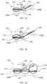
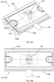
- FIG. 1A schematically depicts a cleaning element 100 attached to a cleaner head 102.
- the cleaning element 100 comprises a cleaning material including a liquid pick-up zone 104 for aligning with dirt inlet(s) (not visible in FIG. 1A ) included in the cleaner head 102.
- the cleaning material e.g. cleaning fabric, further comprises a cleaning liquid application zone 106A, 106B adjacent the liquid pick-up zone 104.
- the cleaning liquid application zone 106A, 106B comprises a first applicator portion 106A and a second applicator portion 106B, with the liquid pick-up zone 104 being arranged between the first applicator portion 106A and the second applicator portion 106B.
- FIG. 1A schematically depicts proper alignment of the liquid pick-up zone 104 with the dirt inlet(s) such that, when the wet cleaning apparatus 100, 102 comprising the cleaning element 100 attached to the cleaner head 102 is moved over the surface to be cleaned in the direction 108, the first applicator portion 106A wets the surface (see the circled part 110 in FIG. 1A ) to be cleaned and the liquid pick-up zone 104 subsequently dries the surface to be cleaned (see the circled part 112 in FIG. 1A ).
- Movement of the wet cleaning apparatus 100, 102 in a direction opposite to the direction 108 may cause the second applicator portion 106B to wet the surface to be cleaned, with the liquid pick-up zone 104 subsequently drying the surface to be cleaned.
- the cleaner head 102 may comprise a protruding element 107 alignable with and protrudable into the liquid pick-up zone 104 of the cleaning material in the direction of the surface to be cleaned.
- the protruding element 107 may be centrally arranged in the cleaner head 102 between the first applicator portion 106A and the second applicator portion 106B to enable rocking on the protruding element 107 in a backwards direction to bring the first applicator portion 106A to and space the second applicator portion 106B apart from the surface to be cleaned, and in a forwards direction to bring the second applicator portion 106B to and space the first applicator portion 106A apart from the surface to be cleaned.
- FIG. 1B schematically depicts local misalignment of the cleaning element 100 with respect to the cleaner head 102 such that the liquid pick-up zone 104 is improperly aligned with the dirt inlet(s). This may mean that when the wet cleaning apparatus 100, 102 is moved over the surface to be cleaned in the direction 108, the first applicator portion 106A wets the surface (see the circled part 110 in FIG. 1B ) to be cleaned but the liquid pick-up zone 104 subsequently provides insufficient drying of the surface to be cleaned (see the circled part 112 in FIG. 1B ).
- FIG. 1C schematically depicts local separation of the cleaning element 100 from the cleaner head 102 such that the second applicator portion 106B becomes detached from the cleaner head 102.
- This may mean that when the wet cleaning apparatus 100, 102 is moved over the surface to be cleaned in the direction 108, the first applicator portion 106A wets the surface (see the circled part 110 in FIG. 1C ) to be cleaned, the liquid pick-up zone 104 subsequently dries the surface to be cleaned (see the circled part 112 in FIG. 1B ), but the detached second applicator portion 106B wets the surface to be cleaned again (see the circled part 114 in FIG. 1C ). This may leave undesirable wet strips on the surface to be cleaned, and risk defeating the purpose of including the dirt inlet(s) in the cleaner head 102 for drying the surface to be cleaned.
- the present disclosure provides a cleaning element 100 comprising a plurality of guiding elements cooperable with a structured portion, e.g. a structured periphery, of the cleaner head 102 to join and align the cleaning element 100 with the cleaner head 102, with the cleaning element 100 further comprising a fastener for securing the aligned cleaning element to the cleaner head.
- the fastener is spaced apart from the plurality of guiding elements across the cleaning material.
- the use of a plurality, in other words more than one, guiding element may assist to minimise the risk of misalignment of the cleaning element 100 with respect to the cleaner head 102.
- the fastener being provided across the cleaning material from the plurality of guiding elements means that the cleaning element 100 can be straightforwardly secured to the cleaner head 102 via the fastener following alignment and joining of the cleaning element 100 to the cleaner head 102 via the guiding elements.
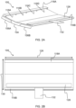
- the plurality of guiding elements 116A, 116B, 116C, 116D comprises, or is defined by, a plurality of pockets.
- each of the plurality of pockets is arranged to receive and engage a tooth of a plurality of teeth included in the structured portion (not visible in FIGs. 2A to 2E ) of the cleaner head 102.
- the plurality of pockets may represent a particularly convenient way of providing the plurality of guiding elements 116A, 116B, 116C, 116D, and may assist to minimise unwanted movement of the cleaning element 100 with respect to the cleaner head 102 in widthways, lengthways and depth directions.
- the cleaning element 100 comprises two, three, five, six, seven, eight, nine, ten or more pockets.
- the alignment provided by the guiding elements 116A, 116B, 116C, 116D in combination with predetermined positioning of the fastener based on the alignment may mean that the securement via the fastener can be made without requiring visual alignment of the fastener with a complementary cleaner head fastener.
- each of the pockets may have the same length as the length of the base of the teeth, be sufficiently wide for full insertion of the teeth into the pockets, and have a depth selected for restricting movement of the teeth in the pockets in the depth direction.
- the cleaning element 100 may be aligned relative to the cleaner head 102 in the lengthways direction.
- the cleaning material comprises a folded over portion 118A defined by folding of the cleaning material onto an upper side thereof facing away from the surface to be cleaned.
- the pockets may be provided between the folded over portion 118A and the upper side of the cleaning material. This may make the guiding elements 116A, 116B, 116C, 116D relatively straightforward to manufacture.
- the folded over portion 118A may, for instance, be attached, e.g. stitched, to the upper side of the cleaning material between the pockets.
- attachment of the folded over portion 118A to the upper side of the cleaning material may define the pockets.
- the cleaning material comprises a further folded over portion 118B opposing the folded portion 118A across the cleaning material.
- the further folded over portion 118B may, similarly to the folded portion 118A, be defined by folding of the cleaning material onto an upper side thereof facing away from the surface to be cleaned.
- the cleaning material in the cleaning liquid application zone 106A, 106B comprises tufts 120 formed from fibers, and a backing layer 122 supporting the tufts 120.
- tufts 120 can assist the cleaning material to follow the contours of the surface to be cleaned and/or may assist the cleaning material to retain dirt particles whilst also minimising the risk of scratching the surface to be cleaned.
- the backing layer 122 can be formed of any suitable backing fabric material, such as polyester.
- the tufts 120 can, for example, be formed from polyamide and/or polyester fibers.
- the cleaning material comprises the folded over portion 118A and/or the further folded over portion 118B defined by folding of the cleaning material onto the upper side thereof facing away from the surface to be cleaned
- the folded over portion 118A and/or the further folded over portion 118B may include the backing layer 122 and tufts 120.
- the tufts 120 may also be provided along, e.g. so as to laterally protrude from, a fold or folds of the cleaning element 100 where the folded portion 118A and/or the further folded portion 118B folds back onto the upper side of the cleaning material. This may assist the cleaning element 100 to, for instance, apply cleaning liquid to a corner located between a floor and a wall extending perpendicularly with respect to the floor.
- the cleaning liquid application zone 106A, 106B may comprise the first applicator portion 106A and the second applicator portion 106B described above in relation to FIGs. 1A to 1C , with the liquid pick-up zone 104 being arranged between the first applicator portion 106A and the second applicator portion 106B.
- the cleaning material in at least one, and preferably both, of the first applicator portion 106A and the second applicator portion 106B may comprise the tufts 120 formed from fibers, and a backing layer 122 supporting the tufts 120.
- An example of this is shown in FIG. 2E .
- the cleaning material in the cleaning liquid application zone 106A, 106B is deformable to bring part of the cleaning material in the cleaning liquid application zone 106A, 106B into contact with the cleaning material in the liquid pick-up zone 104.
- Such deformability of the cleaning material in the cleaning liquid application zone 106A, 106B may enable some of the cleaning liquid to be transferred from the cleaning material in the cleaning liquid application zone 106A, 106B to the cleaning material in the liquid pick-up zone 104 in a controlled manner. In this way, excessive wetting of the surface to be cleaned, for instance by dripping of the cleaning liquid from the cleaning liquid application zone 106A, 106B onto the surface to be cleaned, may be minimised.
- the cleaning material in the cleaning liquid application zone 106A, 106B deforming such that at least part of the cleaning material in the cleaning liquid application zone 106A, 106B contacts the cleaning material in the liquid pick-up zone 104 the latter may be rinsed, e.g. cleaned in situ, with cleaning liquid from the former.
- the cleaning material in the cleaning liquid application zone 106A, 106B is configured to deform upon contact with the surface to be cleaned and/or upon being wetted by liquid, e.g. water.
- Such wetting can be as a result of the cleaning liquid delivered to the cleaning liquid application zone 106A, 106B from cleaning liquid outlet(s) included in the cleaner head 102 and/or due to liquid being present on the surface to be cleaned.
- the cleaning material in the cleaning liquid application zone 106A, 106B comprises the tufts 120 formed from fibers, and the backing layer 122 supporting the tufts, such tufts 120 may be deformable to contact the cleaning material in the liquid pick-up zone 104, e.g. upon contact with the surface to be cleaned and/or upon being wetted by liquid, e.g. water.
- the cleaning liquid can be transferred via the tufts 120 from the cleaning material in the cleaning liquid application zone 106A, 106B to the cleaning material in the liquid pick-up zone 104.
- a key purpose of the liquid pick-up zone 104 of the cleaning material may be to assist to maintain an underpressure in the dirt inlet(s) covered by the liquid pick-up zone 104 when the cleaning element 100 is aligned with the cleaner head 102.
- ASTM F316 - 03, 2019, Test A provides a bubble point pressure measurement. Whilst this standard method was developed for nonfibrous membrane filters, the procedure can be replicated for the cleaning material, and in particular for the liquid pick-up zone 104 thereof, according to the present disclosure.
- the bubble point test for determining the limiting pore diameter is, in summary, performed by prewetting a sample of the cleaning material, increasing the pressure of gas upstream of the sample at a predetermined rate, and watching for gas bubbles downstream to indicate the passage of gas through the maximum diameter pores of the sample.
- the cleaning material in the liquid pick-up zone may (at least to an approximation) have discrete pores extending from one side of the liquid pick-up zone 104 to the other, similarly to capillary tubes.
- the bubble point test is based on the principle that a wetting liquid is held in these capillary pores by capillary attraction and surface tension, and the minimum pressure required to force liquid from these pores is a function of pore diameter. The pressure at which a steady stream of bubbles appears in this test is termed the "bubble point pressure".
- ASTM F316 - 03, 2019, Test A is based on an approximation of the pores as capillary pores having circular cross-sections, and hence the limiting pore diameter should be regarded as merely an empirical estimate of the maximum pore diameter based on this premise.
- the cleaning material has, at least in the liquid pick-up zone 104, a limiting pore diameter as measured using ASTM F316 - 03, 2019, Test A equal to or greater than 15 ⁇ m.
- Such a limiting pore diameter equal to or greater than 15 ⁇ m may assist to maintain a relatively large underpressure in the dirt inlet(s) of the cleaner head 102 whilst ensuring that pores are sufficiently large for efficient liquid transport therethrough.
- the cleaning material has, at least in the liquid pick-up zone 104, a limiting pore diameter as measured using ASTM F316 - 03, 2019, Test A equal to or less than 105 ⁇ m.
- This upper limit for the limiting pore diameter may assist to ensure that sufficient underpressure is maintainable by the cleaning material in the liquid pick-up zone 104.
- ASTM F316 - 03, 2019, Test A assumes cylindrical pores. Purely for the purposes of explanation/illustration (hence should not be regarded as limiting values provided herein for the limiting pore diameter from ASTM F316 - 03, 2019, Test A), it is noted that the limiting pore diameter can be adjusted with a Tortuoise factor (TF), which is an empirical factor derived for solid wire filters, to compensate for non-roundness of the pores.
- TF Tortuoise factor
- Table B shows the above-described limiting pore diameter endpoints when adjusted using the TF.
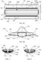
- the cleaning material in the liquid pick-up zone 104 comprises a woven fabric 124A, 124B.
- a woven fabric 124A, 124B may assist to maintain the above-described underpressure in the dirt inlet(s) of the cleaner head 102.
- the woven fabric and in particular a woven microfiber fabric, can be configured, in particular via the tightness of its weave, to satisfy the above ranges for the limiting pore diameter.
- woven microfiber fabric may refer to a fabric formed of synthetic fibers, with the fabric being formed of threads whose titre is less than 1 decitex.
- Such woven microfiber fabrics can comprise, for example, polyester fibers, polyamide fibers, and combinations of polyester and polyamide fibers.
- the woven microfiber fabric may, for example, be a microfiber chamois.
- the cleaning material in the pick-up zone 104 is or comprises a natural chamois, e.g. made from a chamois, deer, goat or sheep hide.
- the woven fabric 124A, 124B comprises a plurality of woven fabric layers, e.g. a plurality of woven microfiber fabric layers.
- Stacking a plurality of woven fabric layers 124A, 124B in this manner may assist maintenance of the underpressure in the dirt inlet(s).
- a first woven fabric layer 124A e.g. a first woven microfiber fabric layer 124A
- a first woven fabric layer 124A may, for example, be arranged such as to be closest to the dirt inlet(s) when the cleaning element 100 is attached to the cleaner head 102, with a second woven fabric layer 124B, e.g. a second woven microfiber fabric layer 124B, being arranged on the first woven fabric layer 124A such that the first woven fabric layer 124A is between the second woven fabric layer 124B and the dirt inlet(s).
- the plurality of woven fabric layers 124A, 124B can be attached to each other in any suitable manner, for example via heat sealing, such as ultrasonic welding.
- Adjacent woven fabric layers 124A, 124B may be attached, e.g. heat sealed, to each other around peripheries of the woven fabric layers 124A, 124B. In this manner, the risk of the attachment, e.g. heat seal, between such adjacent woven fabric layers 124A, 124B interfering with the passage of liquid in the liquid pick-up zone 104 towards the dirt inlet(s) may be minimised.
- the cleaning material in the cleaning liquid application zone 106A, 106B comprises tufts 120 formed from fibers, with a backing layer 122 supporting the tufts 120
- the backing layer 122 may be mounted on the woven fabric 124A, 124B.
- the backing layer 122 is mounted on the second woven fabric layer 124B.
- the cleaning element 100 is elongated so as to define a length 126 of the cleaning element 100, with the plurality of guiding elements being arranged along the length 126.
- Such a lengthways arrangement of the plurality of guiding elements may assist alignment of the cleaning element 100 with respect to the cleaner head 102 (the structured portion, e.g. structured periphery, of the latter correspondingly being provided along its length).
- each of the liquid pick-up zone 104 and the cleaning liquid application zone 106A, 106B may be elongated so as to each longitudinally extend parallel with the length 126 of the cleaning element 100.
- the cleaning element 100 comprises the above-mentioned fastener for securing the aligned cleaning element 100 to the cleaner head 102, with the fastener being spaced apart from the plurality of guiding elements across the cleaning material.
- the fastener may be configured to secure the cleaning element 100 to the cleaner head 102 in widthways (y), lengthways (x) and depth (z) directions.
- the fastener 128 comprises, or is defined by, a hooks-loops fastener, e.g. Velcro ® , portion.
- the hooks-loops fastener portion may, for example, be in the form of a hooks-loops fastener, e.g. Velcro ® , strip extending along the length 126 of the cleaning element 100.
- An advantage of such a hooks-loops fastener portion is that the aligned cleaning element 100 and cleaner head 102 can be secured together in a straightforward manner by pressing the hooks-loops fastener portion against a complementary loops-hooks fastener portion provided on the cleaner head 102.
- the fastener 128 comprises a hole or button for securing to a complementary button or hole included in the cleaner head 102.
- a hole/button may, similarly to the hooks-loops fastener portion, secure the cleaning element 100 to the cleaner head 102 in widthways (y), lengthways (x) and depth (z) directions.
- the fastener 128 is arranged on the upper side of the cleaning element 100 facing away from the surface to be cleaned.
- the guiding elements 116A, 116B, 116C, 116D, e.g. pockets, may also be provided on the upper side of the cleaning element 100.
- the cleaning element 100 can be advantageously aligned with and secured to the cleaner head 102 while the underside of the cleaning element 100 remains in contact with the surface to be cleaned.
- the fastener 128 comprises the hooks-loops fastener portion on the upper side of cleaning element 100
- securing of the aligned cleaning element 100 to the cleaner head 102 can be achieved by simply pressing the underside of the cleaner head 102 onto the upper side of the cleaning element 100.
- the fastener 128 may be spaced apart from the plurality of guiding elements across a width 130 of the cleaning element 100, with the width 130 extending perpendicularly with respect to the length 126 of the cleaning element 100.
- the cleaning element 100 comprises a protrusion 132 arranged to protrude from a periphery of the cleaning element 100 such as to enable a user to trap the protrusion 132 against the surface to be cleaned and thereby immobilise the cleaning element 100 for the joining and alignment with the cleaner head 102.
- the periphery from which the protrusion 132 protrudes may be spaced apart from the plurality of guiding elements 116A, 116B, 116C, 116D across the cleaning material. In this manner, the trapping of the protrusion 132 against the surface to be cleaned can assist to avoid that the cleaning element 100 is pushed away when the cleaning element 100 is being aligned with and joined to the cleaner head 102, e.g. via the pockets of the cleaning element 100 receiving and engaging teeth included in the structured portion, e.g. structured periphery, of the cleaner head 102.
- the user may, for example, trap the protrusion 132 against the surface to be cleaned by pressing down against the protrusion 132 with their foot.
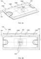
- FIGs. 3A to 3D provide views of a cleaner head 102 to which a cleaning element 100, e.g. the cleaning element 100 described herein in relation to FIGs. 2A to 2C , having a plurality of guiding elements is attachable.
- a cleaning element 100 e.g. the cleaning element 100 described herein in relation to FIGs. 2A to 2C , having a plurality of guiding elements is attachable.
- Such a cleaning element 100 may also have a cleaning material having liquid pick-up zone 104, e.g. a liquid pick-up zone adjacent a cleaning liquid application zone 106A, 106B, as previously described.
- a cleaning material having liquid pick-up zone 104 e.g. a liquid pick-up zone adjacent a cleaning liquid application zone 106A, 106B, as previously described.
- the cleaner head 102 has at least one dirt inlet for receiving dirty liquid when suction is applied to the at least one dirt inlet.
- the at least one dirt inlet is alignable with, so as to be coverable by, the liquid pick-up zone 104 of the cleaning element 100.
- the cleaner head 102 comprises a structured portion 134, e.g. a structured periphery, having a plurality of guiding members 136A, 136B, 136C, 136D, with each of the plurality of guiding members 136A, 136B, 136C, 136D being cooperable with one of the plurality of guiding elements 116A, 116B, 116C, 116D to join and align the cleaner head 102 with the cleaning element 100.
- the cleaner head 102 further comprises a cleaner head fastener 144 for securing the aligned cleaner head 102 to the cleaning element 100.
- the cleaner head fastener 144 is spaced apart from the plurality of guiding members 136A, 136B, 136C, 136D across the cleaner head 102.
- the guiding members 136A, 136B, 136C, 136D comprise, or are defined by, a plurality of teeth, with each tooth of the plurality of teeth being arranged to be received in and engage a pocket of a plurality of pockets included in, or defining, the plurality of guiding elements 116A, 116B, 116C, 116D.
- the plurality of teeth may represent a particularly convenient way of providing the plurality of guiding members 136A, 136B, 136C, 136D of the structured portion 134, and may assist to minimise unwanted movement of the cleaner head 102 with respect to the cleaning element 100 in widthways (y), lengthways (x) and depth (z) directions.
- the structured portion 134 comprises two, three, five, six, seven, eight, nine, ten or more teeth.
- each tooth of the plurality of teeth tapers with extension away from the cleaner head 102. Such tapering can assist location of the tooth in the respective pocket of the cleaning element 100.
- Each tooth may have a base arranged proximal to a main body of the cleaner head 102, with the tooth extending from the base to a tip of the tooth distal from the main body of the cleaner head 102.
- the tapering may mean that the tip is shorter than the base.
- This tapering may, for instance, result in each of the teeth having a trapezoid shape in plan.
- the base and the tip may be connected by one or more curved sections, e.g. a pair of curved sections which curve inwardly towards each other, whose curvature means that the tip is shorter than the base.
- the cleaner head 102 comprises a protruding element 107 alignable with and protrudable into the liquid pick-up zone 104 of the cleaning material in the direction of the surface to be cleaned.
- the protruding element 107 is centrally arranged in the cleaner head 102 between a rearward portion 138 and a forward portion 140 of the cleaner head 102 to enable rocking of the cleaner head 102 on the protruding element 107 in a backwards direction to bring the rearward portion 138 closer to and the forward portion 140 further from the surface to be cleaned, and in a forwards direction to bring the forward portion 140 closer to and the rearward portion 138 further from the surface to be cleaned.
- the above-described first applicator portion 106A may be arranged adjacent the forward portion 140 when the cleaning element 100 shown in FIGs. 2A to 2E is attached to the cleaner head 102 shown in FIGs. 3A to 3D .
- the second applicator portion 106B may accordingly be arranged adjacent the rearward portion 138.
- the cleaning material is thinner in the liquid pick-up zone 104 than in the cleaning liquid application zone 106A, 106B. This may assist alignment and joining of the cleaner head 102 with the cleaning element 100, particularly when the cleaner head 102 includes the protruding element 107, and the cleaning material comprises the first applicator portion 106A and the second applicator portion 106B with the liquid pick-up zone 104 being between the first applicator portion 106A and the second applicator portion 106B and being aligned with the protruding element 107.
- the first and second applicator portions 106A, 106B being thicker than the liquid pick-up zone 104 may make for an uneven landing space for the protruding element 107 of the cleaner head 102 on the upper side of the cleaning element 100.
- This may encourage the cleaner head 102 to rotate such as to assist the guiding members 136A, 136B, 136C, 136D, e.g. teeth, of the structured portion 134 to land on the upper side of the cleaning element 100 in readiness for cooperation with the guiding elements 116A, 116B, 116C, 116D, e.g. pockets, of the cleaning element 100.
- the cleaner head 102 is elongated so as to define a length 142 of the cleaner head 102, with the structured portion 134 being arranged along the length 142.
- Such a lengthways arrangement of structured portion 134 may assist alignment of the cleaning element 100 with respect to the cleaner head 102 (the guiding elements 116A, 116B, 116C, 116D of the former correspondingly being provided along its length 126).
- the cleaner head 102 comprises the above-mentioned cleaner head fastener 144 for securing the cleaner head 102 to the aligned cleaning element 100, with the cleaner head fastener 144 being spaced apart from the plurality of guiding members 136A, 136B, 136C, 136D across the cleaner head.
- the cleaner head fastener 144 may be configured to secure the cleaner head 102 to the cleaning element 100 in widthways (y), lengthways (x) and depth (z) directions.
- the cleaner head fastener 144 comprises, or is defined by, a loops-hooks fastener, e.g. Velcro ® , portion.
- the loops-hooks fastener portion may, for example, be in the form of a loops-hooks fastener, e.g. Velcro ® , strip extending along the length 142 of the cleaner head 102.
- An advantage of such a loops-hooks fastener portion 144 is that the aligned cleaning element 100 and cleaner head 102 can be secured together in a straightforward manner by pressing the loops-hooks fastener portion against a complementary hooks-loops fastener portion provided on the cleaning element 100.
- the cleaner head fastener 144 comprises a hole or button for securing to a complementary button or hole included in the cleaning element 100.
- a hole/button may, similarly to the loops-hooks fastener portion, secure the cleaner head 102 to the cleaning element 100 in widthways (y), lengthways (x) and depth (z) directions.
- the cleaner head fastener 144 is arranged on the underside of the cleaner head 102 facing the surface to be cleaned. Accordingly, when the fastener 128 of the cleaning element 100 comprises the hooks-loops fastener portion on the upper side of cleaning element 100, securing of the aligned cleaning element 100 to the cleaner head 102 can be achieved by simply pressing the underside of the cleaner head 102 onto the upper side of the cleaning element 100.
- the cleaner head fastener 144 may be spaced apart from the plurality of guiding members 136A, 136B, 136C, 136D, e.g. teeth, of the structured portion 134 across a width 146 of the cleaner head 102, with the width 146 extending perpendicularly with respect to the length 142 of the cleaner head 102.
- the cleaner head 102 comprises at least one cleaning liquid outlet 148 through which cleaning liquid is deliverable.
- the at least one cleaning liquid outlet 148 is arranged on the underside of the cleaner head 102 facing the surface to be cleaned and is alignable with, so as to be coverable by, the cleaning liquid application zone 106A, 106B.
- the at least one cleaning liquid outlet 148 need not to be provided on the underside of the cleaner head 102, and may alternatively be provided elsewhere in the cleaner head 102 provided that the cleaning liquid can be delivered via the cleaning liquid outlet(s) 148 to reach the surface to be cleaned.
- the cleaning liquid can comprise, or consist of, water.
- the cleaning liquid can be an aqueous cleaning liquid.
- the cleaning liquid is an aqueous detergent solution.
- the cleaner head 102 may comprise a plurality of cleaning liquid outlets 148 arranged along the length 142 of the underside of the cleaner head 102.
- the at least one cleaning liquid outlet 148 comprises a first plurality of cleaning liquid outlets 148 arranged along the length 142 of the cleaner head 102 and being alignable with the first applicator portion 106A included in the cleaning liquid application zone 106A, 106B, and a second plurality of cleaning liquid outlets 148 arranged along the length 142 of the cleaner head 102 and being alignable with the second applicator portion 106B included in the cleaning liquid application zone 106A, 106B.
- the first applicator portion 106A may be arranged to apply cleaning liquid delivered from the first plurality of cleaning liquid outlets 148 to the surface to be cleaned
- the second applicator portion 106B may be arranged to apply cleaning liquid delivered from the second plurality of cleaning liquid outlets 148 to the surface to be cleaned.
- the cleaner head 102 comprises a cleaning liquid distribution strip 150A comprising at least some of the cleaning liquid outlets 148.
- the cleaning liquid distribution strip 150A may comprise a channel which can be supplied with the cleaning liquid, e.g. from a suitable cleaning liquid reservoir (not visible in FIGs. 3A to 3D ) via one or more inlets.
- the inlet(s) may be provided at or proximal to an end or both ends of the cleaning liquid distribution strip 150A, however it is also conceivable that the inlet is provided in a central position along the length of the cleaning liquid distribution strip 150A.
- the cleaning liquid may exit the cleaning liquid distribution strip 150A via apertures in the cleaning liquid distribution strip 150A which define the cleaning liquid outlets 148.
- Such apertures may be dimensioned such that passage of the cleaning liquid, e.g. aqueous cleaning liquid, through the apertures is restricted, due to the surface tension of the cleaning liquid, while the channel is being filled, but with passage of the cleaning liquid through all of the apertures of the cleaning liquid distribution strip 150A at the same time being permitted once the channel has been filled. This may enable relatively uniform wetting of the surface to be cleaned across the length 142 of the cleaner head 102.
- each cleaning liquid outlet 148 may have, for example, a diameter less than 1 mm, for example a diameter in the range of 0.1 to 1 mm, preferably 0.1 to 0.8 mm, most preferably 0.1 to 0.5 mm, such as about 0.3 mm.
- the cleaning liquid distribution strip 150A can be formed of any suitable material, such as a metal, a metal alloy, e.g. stainless steel, and/or a polymer. Forming the cleaning liquid distribution strip 150A from a polymer can make the cleaning liquid distribution strip 150A more lightweight and/or cheaper to manufacture.
- the cleaner head 102 comprises the cleaning liquid distribution strip 150A arranged to deliver cleaning liquid in the rearward portion 138 and a further cleaning liquid distribution strip 150B whose further apertures define cleaning liquid outlets 148 which deliver the cleaning liquid in the forward portion 140.
- Both the cleaning liquid distribution strip 150A and the further cleaning liquid distribution strip 150B may longitudinally extend parallel with the length 142 of the cleaner head 102, as best shown in FIG. 3C .
- the cleaning element 100 comprises the first applicator portion 106A and the second applicator portion 106B
- the first applicator portion 106A may be arranged to apply cleaning liquid delivered from the further cleaning liquid distribution strip 150B to the surface to be cleaned
- the second applicator portion 106B may be arranged to apply cleaning liquid delivered from the cleaning liquid distribution strip 150A to the surface to be cleaned.
- each of the at least one dirt inlet is defined by an opening of a tube or tubes fluidly connected or connectable to an underpressure generator (not visible).
- dirt inlets Any suitable number of dirt inlets can be contemplated, such as one, two, three, four, five, six, or more.
- the at least one dirt inlet comprises a plurality of dirt inlets arranged along the length 142 of the cleaner head 102.
- these may, for instance, have the same dimensions as each other.
- the dirt inlets may be spaced relative to each other along the length 142 of the cleaner head 102 such as to provide relatively uniform suction along the length 142 of the cleaner head 102.
- the distance along the length 142 between a centre position of the cleaner head 102 and a centre of one dirt inlet of a pair of dirt inlets may be the same, or substantially the same, as the distance along the length between the centre position and a centre of the other dirt inlet of the pair of dirt inlets.
- this may be arranged in a central position of the cleaner head 102 to provide a relatively symmetrical suction profile along the length 142 of the cleaner head 102.
- the cleaner head 102 may comprise a porous material 152 covering each of the at least one dirt inlet.
- the porous material 152 covering each of the at least one dirt inlet may assist to maintain an underpressure in the dirt inlet(s) with or without constant flow being applied thereto, for instance by an underpressure generator, e.g. pump, fluidly connected to the dirt inlet(s).
- an underpressure generator e.g. pump
- the surface tension of the liquid retained in the pores of the porous material 152 can assist to maintain the underpressure.
- This surface tension can be overcome, meaning that the air-liquid surface is removed, at a point (or points) on the exterior of the porous material 152 which come into contact with liquid, causing liquid to be transported through the porous material 152 in the direction of the dirt inlet(s).
- a limiting pore diameter of the porous material 152 as measured using ASTM F316 - 03, 2019, Test A is equal to or greater than 15 ⁇ m.
- Such a limiting pore diameter equal to or greater than 15 ⁇ m may assist to maintain a relatively large underpressure whilst ensuring that pores are sufficiently large for efficient liquid transport therethrough.
- a limiting pore diameter of the porous material 152 as measured using ASTM F316 - 03, 2019, Test A is equal to or less than 105 ⁇ m. This upper limit for the limiting pore diameter may assist to ensure that sufficient underpressure is maintainable by the porous material 152.
- Bacteria tends to be characterized by having a relatively small size.
- an Escherichia coli cell which can be regarded as an "average" sized bacterium, is about 2 ⁇ m long and 0.5 ⁇ m in diameter.
- porous materials 152 and cleaning materials (at least in the liquid pick-up zone 104) whose pore size is larger than 2 ⁇ m may permit such bacteria to pass therethrough. In this way, bacteria can be removed from the surface to be cleaned.
- the porous material 152 can comprise one or more of a porous fabric, a porous plastic, and a foam.
- Such a porous plastic may, for example, take the form of a sintered mesh of plastic granules.
- porous material 152 includes such a porous plastic
- one or more further porous material layers e.g. comprising a porous fabric, such as a woven porous fabric, may be arranged on an external surface of the porous plastic.
- Such further porous material layer(s) may be more wettable by water than the porous plastic and thus more appropriate for being closer to the surface to be cleaned when wetted by water.
- porous material comprising a woven fabric, and most preferably a woven microfiber fabric.
- a woven microfiber fabric may facilitate attainment of the requisite underpressure in the wet cleaning apparatus.
- Such a woven fabric, and in particular such a woven microfiber fabric can be configured, in particular via the tightness of its weave, to satisfy the above ranges for the limiting pore diameter, as previously described in respect of the cleaning material (at least) in the liquid pick-up zone 104.
- Table C Characteristic Specification Fabric set - plain weave Density - > 60 yarns/cm in warp - > 60 yarns/cm in weft Basis weight - ⁇ 200 g/m2 Composition - Polyester 80%, Polyamide 20% Warp yarn - Low twist yarn of Polyester filamentary fibres of ⁇ 18 ⁇ m diameter, preferred of edged cross-section. - Yarn count: of 60-70 filamentary fibres in cross-section, low twist. Weft yarn - Low twists yarn of Polyester/Polyamide microfibers (pie cross-section). Fibre cross-section of up to 16 ⁇ m - Yarn count: of ⁇ 100 microfibres in cross-section, low twisted. Permeability - 15 L/h/cm 2
- the porous material 152 comprises a porous material layer sealingly attached to the at least one dirt inlet.
- Such sealing attachment can assist to maintain an underpressure in the covered dirt inlet(s) because loss of the underpressure via leakage between the dirt inlet(s) and the porous material layer is minimised or prevented.
- the sealing attachment can be implemented in any suitable manner, such as by gluing or welding the porous material layer around each of the at least one dirt inlet, for example gluing and/or welding the porous material layer to the above-mentioned tube(s) around the opening(s) defining the dirt inlet(s).
- a liquid pick-up region of the porous material layer may be delimited by sealing attachment of the porous material layer around the, e.g. each of the, at least one dirt inlet.
- the liquid pick-up region is arranged relative to the at least one cleaning liquid outlet 148 such as to allow the cleaning liquid to bypass, e.g. pass around a periphery of, the liquid pick-up region to reach, or at least be directed towards, the surface to be cleaned.
- the porous material 152 can be attached, e.g. against the cleaner head 102 or a component of the cleaner head 102, around the dirt inlet(s) at least partly by being sucked thereagainst by the flow provided by an underpressure generator.
- the porous material 152 comprises, in addition to the porous material layer, one or more further porous material layers.
- porous material 152 comprising a stack of porous material layers in this manner, a greater underpressure may be maintainable in the dirt inlet(s).
- the one or more further porous material layers may be arranged on an external surface of the porous material layer, with an external surface of the further porous material layer furthest from the at least one dirt inlet in a thickness direction of the porous material being adjacent to, e.g. contacting, the liquid pick-up zone 104 of the cleaning material of the cleaning element 100.
- the porous material 152 or the combination of the cleaning material in the liquid pick-up zone 104 and the porous material 152, has a thickness of less than or equal to 10 mm, more preferably less than or equal to 5 mm, and most preferably less than or equal to 3 mm. Such a maximum thickness may contribute to minimising of flow resistance through the porous material 152 or, as the case may be, through the combination of the cleaning material in the liquid pick-up zone 104 and the porous material 152.
- the thickness of the porous material 152 or the combination of the cleaning material in the liquid pick-up zone 104 and the porous material 152 can be determined by using a 0.01 mm precision gauge and two ground metal plates (with the upper plate by which the normal pressure is applied being 70 mm x 30 mm, and the lower plate on which the sample is supported having a larger area than the 70 mm x 30 mm surface of the upper plate for ease of alignment) for receiving the sample therebetween.
- the arrangement is configured to apply a pressure normal to the sample of the porous material (70 mm x 30 mm) of 864.2 N/m 2 .
- Table D Metal plate parameters Length 70 mm Area of sample 2100 mm 2 Width 30 mm Total mass 185 g mass 85 g Total force 1.81 N Fn (gauge force) 100 g Pressure 864.2 N/m 2
- the porous material 152 and/or the cleaning material in the liquid pick-up zone 104 may be particularly susceptible to wear, and such wear can risk compromising underpressure-maintaining/liquid pick-up performance. Accordingly, the porous material 152 and/or the cleaning material in the liquid pick-up zone 104 can comprise a plurality of differently coloured layers which layers are progressively worn by use such that the colour of the porous material 152 and/or the cleaning material in the liquid pick-up zone 104 serves as a wear indicator.
- the cleaner head 102 can be attached or may be attachable to a suitable handle (not visible) to assist moving the cleaner head 102.
- the cleaner head 102 may comprise a coupling point 154 to which such a handle may be coupled, e.g. pivotably coupled.
- the cleaner head 102 comprises an elastomeric material (not visible in FIGs. 3A to 3D ) on which the porous material 152 is arranged.
- the resilient deformation of such an elastomeric material may lessen the risk of damage to the porous material 152 should, for example, a relatively hard protrusion be present on the surface to be cleaned which comes into contact with the porous material 152.
- the elastomeric material may assist the porous material 152 to follow any contours of the surface to be cleaned, e.g. for the purpose of minimising the risk of liquid stripes being left on the surface to be cleaned.
- the elastomeric material can, for instance, be or comprise silicone rubber.
- Other elastomeric materials such as a polydiene, e.g. polybutadiene, a thermoplastic elastomer, and so on, can also be contemplated for inclusion in, or defining of, the elastomeric material.
- the elastomeric material can be less than 50 Shore A, preferably less than 20 Shore A, most preferably less than 10 Shore A.
- the elastomeric material is 4 Shore A silicone rubber.
- the protruding element 107 may comprise the elastomeric material.
- the cleaner head 102 may comprise a support 166, e.g. a rigid support 166, and the protruding element 107 is mounted via attachment to the support 166.
- the at least one dirt inlet comprises, or is defined by, one or more channels extending through the elastomeric material.
- the elastomeric material may comprise a curved surface on which the porous material 152 is arranged.
- the porous material may follow the curvature of the curved surface.
- Such a curved, e.g. rounded, surface of the elastomeric material may assist to minimise the area of the liquid pick-up region which approaches the surface to be cleaned, thereby assisting to minimise resistance to motion across the surface to be cleaned.
- the porous material layer is sealingly attached to the elastomeric material.
- the porous material layer may, for example, be sealingly attached to the elastomeric material via heat sealing.
- the cleaner head 102 comprises an impermeable portion to which the porous material layer is sealingly attached, with the at least one dirt inlet being defined by an aperture or apertures provided in the impermeable portion and/or being defined between the impermeable portion and the porous material layer.
- the at least one dirt inlet is exposed to a cavity between the porous material layer and the impermeable portion, with a liquid transporting support structure being arranged in the cavity, and providing one or more flow paths in the liquid pick-up region between the porous material layer and the at least one dirt inlet.
- the liquid transporting support structure may provide one or more flow paths in the liquid pick-up region between the porous material layer and the at least one dirt inlet.
- the porous material layer e.g. a woven fabric, and/or the impermeable portion, e.g. a polymer film, may be pliable such that an underpressure may cause the porous material layer and the impermeable portion to be drawn towards each other. This may risk restriction of passage of liquid from the porous material layer to the at least one dirt inlet.
- the liquid transporting support structure may assist to ensure that, in spite of such drawing of the porous material layer and the impermeable portion towards each other, liquid can still be transported from the porous material layer, and in particular pores of the porous material layer, to the at least one dirt inlet.
- the liquid transporting support structure can, for example, comprise one or more mesh layers.
- the present disclosure provides an attachable (and/or detachable) member 156 per se.
- the attachable member 156 may be suitable for attaching to the cleaner head 102.
- the attachable member 156 comprises the porous material layer 158; and at least one dirt inlet 160 to which an underpressure generator is fluidly connectable when the attachable member 156 is attached to the cleaner head 102, with a liquid pick-up region of the porous material layer 158 being delimited by sealing attachment of the porous material layer 158 around the at least one dirt inlet 160.
- Such an attachable member 156 may enable replacement of the porous material layer 158 without requiring re-sealing of the porous material layer 158 to the dirt inlet(s) 160.
- the attachable member 156 comprises the elastomeric material 162 on which the porous material layer 158 is arranged.
- the porous material layer 158 is sealingly attached to a support member 168 included in the attachable member 156 via seals 164, e.g. heat seals.
- the porous material layer 158 is sealingly attached to the dirt inlet(s) 160, which dirt inlet(s) 160 is or are, in this example, defined in, i.e. delimited by, the elastomeric material 162.
- the dirt inlets 160 are in the form of channels extending through the elastomeric material 162.
- the attachable member 156 can be attached, e.g. detachably coupled, to the support 166, e.g. the rigid support 166, included in the cleaner head 102 in any suitable manner, such as by the attachable member 156, e.g. the support member 168 thereof, having a ridge member which push-fits into a slot defined in the support 166, or by the support 166 having such a ridge member which push-fits into a slot defined in the attachable member 156, e.g. in the support member 168.
- a further porous material layer 170 is also included in the attachable member 156 in the example shown in FIGs. 4 and 5 . It is noted that the process of heat sealing, e.g. via ultrasonic welding, the porous material layer 158 to the plastic support member 168 also results in the further porous material layer 170 becoming adhered to the porous material layer 158.
- FIGs. 4 and 5 differ from each other in that the liquid transporting support structure 172 shown in FIG. 4 is defined by a surface pattern arranged on and/or in the surface of the elastomeric material 162, whereas the liquid transporting support structure 172 shown in FIG. 5 is in the form of a mesh layer.
- the present disclosure further provides a wet cleaning apparatus comprising the cleaning element 100 as described herein and the cleaner head 102 as described herein.
- FIGs. 6A to 6C provide views of such a wet cleaning apparatus comprising the cleaning element 100 as described above in respect of FIGs. 2A to 2E and the cleaner head 102 as described above in respect of FIGs. 3A to 3D to which the cleaning element 100 is attached.
- FIG. 7 schematically depicts a method of attaching a cleaning element 100 having a cleaning material to a cleaner head 102.
- the method comprises cooperating 174 a plurality of guiding elements 116A, 116B, 116C, 116D of the cleaning element 100 with a structured portion 134 of the cleaner head 102 to join and align the cleaning element 100 with the cleaner head 102, and securing 176 the aligned cleaning element 100 to the cleaner head 102 using a fastener 128 included in the cleaning element 100, with the fastener 128 being spaced apart from the plurality of guiding elements 116A, 116B, 116C, 116D across the cleaning material.
- the cleaning element 100 and the cleaner head 102 are being aligned in step 174, it is noted that the "triangular" shape of the cleaner head 102, resulting from the protruding element 107 in this non-limiting example, may preclude securing of the fastener 128 to the cleaner head 102 while the cooperating 174 is taking place. Thus, a portion of the cleaner head 102 is free to touch and slide over the cleaning element 100 to facilitate the alignment.
- the user Only when the cleaning element 100 and the cleaner head 102 are fully aligned with each other may the user either decide to gently tap the cleaner head 102, tilting it backwards and connect the fasteners 128, 144, e.g. Velcro ® strips, to fully fixate the cleaning element 100 to the cleaner head 102, or implement this automatically by the first mopping stroke as this will also tilt the cleaner head 102 backwards to secure the cleaning element 100 to the cleaner head 102.
- the fasteners 128, 144 e.g. Velcro ® strips
- the cleaning element 100 can be detached from the cleaner head 102, e.g. to enable washing of the cleaning element 100 and/or replacement of the cleaning element 100 when the cleaning material has become overly worn, by unfastening the fastener 128, followed by disengaging the plurality of guiding elements 116A, 116B, 116C, 116D of the cleaning element 100 from the structured portion 134 of the cleaner head 102.
- the cleaner head 102 and cleaning element 100 can be moved across the surface to be cleaned at a certain speed.
- ⁇ P 1125 Pa
- ⁇ P 5000 Pa
- the wet cleaning apparatus comprises an underpressure generator for supplying suction to the at least one covered dirt inlet.
- the underpressure generator may, for example, be or comprise a positive displacement pump, such as a peristaltic pump.
- a positive displacement pump can assist to maintain the underpressure in the dirt inlet(s) after the underpressure generator has been deactivated, e.g. switched off, because the pump design inherently restricts backflow from the pump outlet. This, in turn, may alleviate problematic liquid release from the liquid pick-up zone, for instance following cleaning of the surface to be cleaned and/or during stowing of the wet cleaning apparatus in a storage area after use.
- the underpressure generator is configured to provide a pressure difference between an inside of the wet cleaning apparatus and atmospheric pressure for drawing fluid through the liquid pick-up zone and, when present, the porous material 152 and into the at least one dirt inlet 160, wherein the pressure difference is in a range of 2000 Pa to 13500 Pa.
- Both endpoints of the 2000 Pa to 13500 Pa range for the pressure difference are purposively selected.
- the 2000 Pa lower limit reflects that the cleaner head 102 and cleaning element 100 will typically be moved over a surface to be cleaned, e.g. a floor, and as the speed of the cleaner head 102 and cleaning element 100 over the floor increases, the concomitant drop in static pressure means that liquid is pulled towards the floor. Such behaviour can be approximated by a Bernoulli equation, as described above.
- the 2000 Pa minimum underpressure is correspondingly set according to a minimum typical speed with which a user moves the cleaner head 102 and cleaning element 100 over the surface to be cleaned, thereby to ensure that the underpressure is sufficient to pull liquid into the inside of the wet cleaning apparatus without requiring that the user has to significantly slow or cease movement of the cleaner head 102 and cleaning element 100 over the surface to be cleaned in order for the liquid to be picked up.
- the 13500 Pa upper limit is defined for the purpose of ensuring that liquid transport through the liquid pick-up zone 104 and, when present, the porous material 152 is sufficiently rapid.
- the pressure difference is 5000 Pa to 9000 Pa, and most preferably 7000 Pa to 9000 Pa. These ranges may reflect particularly enhanced liquid pick-up observed during movement of the cleaner head 100 and cleaning element 102, combined with relatively low flow resistance through the liquid pick-up zone 104 and, when present, the porous material 152.
- the pressure difference can be directly and positively verified in a given wet cleaning apparatus in which the cleaning element 100 is attached to the cleaner head 102 by, for example, drilling a hole in a tube of the wet cleaning apparatus which is fluidly connected with the dirt inlet(s) 160 and using the hole to couple to a pneumatic pressure sensor itself having a tube with a membrane covering an end thereof; the sensor being thus connected using an airtight connection.
- the sensor may be arranged to avoid disturbing the flow, hence the skilled person will arrange the sensor to avoid, for instance, creating a bypass flow. No flow may be towards or from the sensor: only pressure is transmitted. In this way, the flow of the appliance may never be compromised (hence may remain at the set level in spite of the sensor installation).
- the above-mentioned tube of the wet cleaning apparatus can be cut into two, and a T-shape connector installed in an airtight manner therebetween in order to install the sensor.
- a further advantage of the liquid pick-up principle described herein may be the lower power consumption, particularly in examples in which the underpressure generator is powered.
- a conventional vacuum cleaner that is capable of picking up water needs to generate significant airspeed and/or brushpower in order to generate enough shear force on water droplets to cause them to enter the vacuum cleaner.
- Typical power consumption values for such vacuum cleaners are several hundred watts.
- the power is 8.3*10 -3 watts.
- the underpressure generator be powered using, for instance, a conventional battery providing a runtime of 28 minutes in a wet cleaning apparatus whose mechanical power consumption is around 50 watts, the runtime in the present case would be 168000 minutes, in other words more than 100 days.
- a powered wet cleaning apparatus having the cleaner head 102 and cleaning element 100 according to the present disclosure may therefore only rarely require recharging of its battery (in examples in which such a battery is included to power the wet cleaning apparatus), and/or may be made more lightweight, due to the minimal battery capacity needed for, for example, a 1 hour runtime. Regarding the latter, it is noted that a battery for a conventional handheld wet cleaning apparatus may weigh around 0.5 kg, and may thus contribute significantly to the overall weight of the wet cleaning apparatus.
- the underpressure generator is configured to supply suction by providing a flow rate through the cleaning material in the liquid pick-up zone 104 and, when present, the porous material 152 which is less than or equal to 2000 cm 3 /minute.
- Such a flow rate may be significantly lower than for the conventional wet vacuum cleaners mentioned above. Since power is equal to flow rate multiplied by the pressure difference, by combining this maximum 2000 cm 3 /minute flow rate with the above-described maximum 13500 Pa pressure difference as a maximum power consumption scenario, the power consumption of the wet cleaning apparatus may be minimised. This may enable the wet cleaning apparatus to made relatively compact, e.g. using a smaller battery, and/or to have a relatively long runtime.
- the underpressure generator may be configured to supply suction by providing a flow rate through the liquid pick-up zone 104 of the cleaning material and, when present, the porous material 152 which is equal to or greater than 15 cm 3 /minute. This may contribute to the pick-up of liquid from the surface to be cleaned being sufficiently rapid.
- the 15 cm 3 /minute lower limit may, in some embodiments, be set to equal or exceed a flow rate of a cleaning liquid from cleaning liquid outlet(s) 148 included in the cleaner head 102.
- the underpressure generator is configured to provide a flow rate through the liquid pick-up zone 104 and, when present, the porous material 152 which is equal to or greater than 40 cm 3 /minute. As well as contributing to efficient liquid pick-up, this 40 cm 3 /minute may, in some embodiments, be set to equal or exceed a flow rate of a cleaning liquid from cleaning liquid outlet(s) 148 included in the cleaner head 102, with the minimum cleaning liquid flow rate being set to ensure plentiful supply of the cleaning liquid to the surface to be cleaned.
- the underpressure generator may be configured to provide a flow rate through the liquid pick-up zone 104 of the cleaning material and, when present, the porous material 152 in the range of 80 to 750 cm 3 /minute, even more preferably 100 to 300 cm 3 /minute, and most preferably 150 to 300 cm 3 /minute.
- a flow rate may capitalise on the underpressure-maintaining capability of the liquid pick-up zone 104 and, when present, the porous material 152, and may ensure sufficient liquid pick-up whilst limiting energy consumption.
- the wet cleaning apparatus may also include a dirty liquid collection tank.
- the underpressure generator may be arranged to draw liquid from the at least one dirt inlet 160 to the dirty liquid collection tank.
- the dirty liquid collection tank can be arranged in any suitable manner relative to, e.g. upstream or downstream of, the underpressure generator.
- the wet cleaning apparatus comprises a cleaning liquid supply for supplying cleaning liquid to the cleaner head 102 for delivery towards the surface to be cleaned via the at least one cleaning liquid outlet(s) 148.
- a cleaning liquid supply may, for example, comprise a cleaning liquid reservoir and a delivery arrangement, e.g. a delivery arrangement comprising a pump, for transporting the cleaning liquid to and through the at least one cleaning liquid outlet 148.
- the above-mentioned handle may support or include at least part of the underpressure generator fluidly connected to the at least one dirt inlet 160 and/or the dirty liquid collection tank.
- at least part of the cleaning liquid supply e.g. the cleaning liquid reservoir and/or the delivery arrangement, may be supported by or included in the handle.
- the cleaning liquid supply and the at least one cleaning liquid outlet 148 may be configured to provide a continuous delivery of the cleaning liquid towards the surface to be cleaned.
- the underpressure generator may be configured to provide suction to the at least one dirt inlet 160 at the same time as, in other words simultaneously to, the cleaning liquid supply supplying the cleaning liquid to and through the at least one cleaning liquid outlet 148.
- the cleaning liquid supply and the underpressure generator may, for instance, be configured such that the flow of the cleaning liquid delivered through the at least one cleaning liquid outlet 148 is equal to or lower than the flow provided through the liquid pick-up zone 104 and, when present, the porous material 152 to the at least one dirt inlet 160 by the underpressure generator. This may assist to ensure that the surface to be cleaned does not become excessively wet with the cleaning liquid.
- the flow of cleaning liquid may be in the range of 20 to 60 cm 3 /minute
- the flow provided by the underpressure generator may be in the range of 40 to 2000 cm 3 /minute, more preferably 80 to 750 cm 3 /minute, even more preferably 100 to 300 cm 3 /minute, and most preferably 150 to 300 cm 3 /minute.
- a positive displacement pump is employed as the underpressure generator, at 1 or 2 liter/minute flows, such a pump may become relatively bulky and noisy, hence lower flow rates may assist in keeping the wet cleaning apparatus relatively small, quiet and lightweight.
- a flow rate of the underpressure generator which is equal to the flow rate of the cleaning liquid provided by the cleaning liquid supply may suffice.
- a 50 cm 3 puddle of water encountered by the wet cleaning apparatus having a cleaning liquid flow rate of 40 cm 3 /minute and a flow rate provided by the underpressure generator of 50 cm 3 /minute may mean that it would take about 5 minutes to take in all the water (resulting in a 5 minute drop in underpressure, hence a 5 minute period in which the floor stays significantly more wet (because the puddle keeps on being spread).
- a 250 cm 3 /minute flow rate provided by the underpressure generator may reduce this to a 14 second period. The flow rate provided by the underpressure generator being above the flow rate of the cleaning liquid provided by the cleaning liquid supply may permit the system to revert to equilibrium more quickly after such a disturbance.
- the wet cleaning apparatus may be or comprise, for example, a wet mopping device, a window cleaner, a sweeper, or a wet vacuum cleaner, such as canister-type, stick type, or upright type wet vacuum cleaner.
- the wet cleaning apparatus is a battery-powered (or battery-powerable) wet cleaning apparatus, such as a battery-powered (or battery-powerable) wet mopping device, in which the underpressure generator, e.g. pump, is powered (or powerable) by a battery electrically connected (or connectable) thereto.
- the underpressure generator e.g. pump
- the underpressure generator e.g. pump
- the porous material 152 covering the dirt inlet(s) 160 to which the suction of the underpressure generator is provided is provided.
- FIG. 8 schematically depicts an exemplary wet cleaning apparatus 178 in the form of a wet vacuum cleaner.
- the wet cleaning apparatus 178 comprises the above-described dirty liquid collection tank 180, and the cleaning liquid reservoir 182.
- the cleaner head 102 and cleaning element 100 included in the wet vacuum cleaner can be moved over the surface to be cleaned, in this example assisted by the wheels 184 included in the wet vacuum cleaner.
- the wet cleaning apparatus 178 may in some examples be or comprise a robotic wet vacuum cleaner or a robotic wet mopping device configured to autonomously move the cleaner head 102 and cleaning element 100, e.g. in a single cleaning direction, on the surface to be cleaned, such as the surface of a floor.
- FIG. 9 schematically depicts an exemplary wet cleaning apparatus 178 in the form of a robotic wet vacuum cleaner.
- the robotic wet vacuum cleaner may move autonomously on the surface to be cleaned, e.g. via automated control over the wheels 184.
- the cleaning liquid stored in the cleaning liquid reservoir 182 can be delivered to the surface to be cleaned, and liquid can be picked up via the covered dirt inlet(s) 160 of the cleaner head 102 and collected in the dirty liquid collection tank 180, during autonomous movement of the robotic wet vacuum cleaner.
- the underpressure generator and/or the cleaning liquid supply may also be under automated control.
Landscapes
- Engineering & Computer Science (AREA)
- Mechanical Engineering (AREA)
- Cleaning Implements For Floors, Carpets, Furniture, Walls, And The Like (AREA)
Abstract
Provided is a cleaning element (100) for attaching to a cleaner head, which cleaner head has a structured portion and at least one dirt inlet. The cleaning element comprises a cleaning material for contacting a surface to be cleaned. The cleaning material comprises a liquid pick-up zone (104) alignable with, so as to cover, the at least one dirt inlet, and a cleaning liquid application zone (106A, 106B) adjacent the liquid pick-up zone. The cleaning liquid application zone is for applying cleaning liquid to the surface to be cleaned. The cleaning element comprises a plurality of guiding elements (116A, 116B, 116C, 116D) cooperable with the structured portion to join and align the cleaning element with the cleaner head. The cleaner head further comprises a fastener (128) for securing the aligned cleaning element to the cleaner head. The fastener is spaced apart from the plurality of guiding elements across the cleaning material. Further provided is the cleaner head having the structured portion and the at least one dirt inlet, and a wet cleaning apparatus comprising the cleaning element and the cleaner head.
Description
- This invention relates to a cleaning element for attaching to a cleaner head, a cleaner head to which such a cleaning element is attachable, and a wet cleaning apparatus comprising the cleaner head and the cleaning element. The cleaning element, cleaner head and wet cleaning apparatus can be used, for example, for cleaning a floor, an indoor surface or a window.
- Wet cleaning apparatuses, for example wet mopping devices, are known which remove water from a surface to be cleaned. Such wet cleaning apparatuses can also apply cleaning liquid, e.g. water, to the surface to be cleaned, and then remove the liquid, e.g. with a suitable cloth.
- Some wet cleaning apparatuses have powered pick-up functionality for removing the water from the surface to be cleaned. Wet vacuum cleaners, for instance, may pick up liquid by generating sufficient airspeed (e.g. at least 10 m/s) and/or brushpower to exert enough shear force on liquid droplets to cause them to enter the device. Typical power consumption values for such vacuum cleaners are relatively high, for example in the order of several hundred watts.
- A further challenge can arise when the wet cleaning apparatus is arranged to deliver cleaning liquid as well as pick up the liquid using suction. Providing both functionalities can, in at least some designs, risk that the cleaning liquid is used inefficiently.
- When, for example, a replaceable/detachable cleaning material, e.g. a cleaning fabric, is included in the wet cleaning apparatus, it may be challenging for the user to (re-)attach the cleaning material to the wet cleaning apparatus, e.g. to a cleaner head included in the wet cleaning apparatus, in a reliable manner.
- The invention is defined by the claims.
- According to examples in accordance with an aspect of the invention there is provided a cleaning element for attaching to a cleaner head, which cleaner head has a structured portion and at least one dirt inlet, the cleaning element comprising: a cleaning material for contacting a surface to be cleaned, the cleaning material comprising a liquid pick-up zone alignable with, so as to cover, the at least one dirt inlet, and a cleaning liquid application zone adjacent the liquid pick-up zone for applying cleaning liquid to the surface to be cleaned; a plurality of guiding elements cooperable with the structured portion to join and align the cleaning element with the cleaner head; and a fastener for securing the aligned cleaning element to the cleaner head, the fastener being spaced apart from the plurality of guiding elements across the cleaning material.
- Cleaning elements which are attachable and detachable from a cleaner head offer several advantages, in particular the capability to remove the cleaning element for washing after use and/or replacement when the cleaning material, e.g. cleaning fabric, has become overly worn. However, challenges have been encountered when designing such a cleaning element for a cleaner head having at least one dirt inlet for receiving dirty liquid when suction is applied to the at least one dirt inlet. In particular, alignment of the liquid pick-up zone of the cleaning material with the at least one dirt inlet, such that the liquid passes through the liquid pick-up zone to reach the at least one dirt inlet, has been found difficult to reliably achieve by conventional cleaning element attachment methods.
- The use of a plurality, in other words more than one, guiding element may assist to minimise the risk of misalignment of the cleaning element with respect to the cleaner head. Moreover, the fastener being provided across the cleaning material from the plurality of guiding elements means that the cleaning element can be straightforwardly secured to the cleaner head via the fastener following alignment and joining of the cleaning element to the cleaner head via the guiding elements.
- In some embodiments, the cleaning element is elongated so as to define a length of the cleaning element, with the plurality of guiding elements being arranged along the length. Such a lengthways arrangement of the plurality of guiding elements may assist alignment of the cleaning element with respect to the cleaner head (the structured portion of the latter correspondingly being provided along its length).
- In such embodiments, each of the liquid pick-up zone and the cleaning liquid application zone may be elongated so as to each longitudinally extend parallel with the length of the cleaning element.
- In some embodiments, the plurality of guiding elements comprises, or is defined by, a plurality of pockets. In such embodiments, each of the plurality of pockets is arranged to receive and engage a tooth of a plurality of teeth included in the structured portion of the cleaner head. The plurality of pockets may represent a particularly convenient way of providing the plurality of guiding elements, and may assist to minimise unwanted movement of the cleaning element with respect to the cleaner head in widthways, lengthways and depth directions.
- The fastener may be configured to secure the cleaning element to the cleaner head in widthways, lengthways and depth directions.
- In some embodiments, the fastener is arranged on an upper side of the cleaning element facing away from the surface to be cleaned. In such embodiments, the guiding elements, e.g. pockets, may also be provided on the upper side of the cleaning element. Thus, the cleaning element can be advantageously aligned with and secured to the cleaner head while the underside of the cleaning element remains in contact with the surface to be cleaned.
- Alternatively or additionally, the fastener may comprise a hooks-loops fastener, e.g. Velcro®, portion. The hooks-loops fastener portion may, for example, be in the form of a hooks-loops fastener, e.g. Velcro®, strip extending along the length of the cleaning element. An advantage of such a hooks-loops fastener portion is that the aligned cleaning element and cleaner head can be secured together in a straightforward manner by pressing the hooks-loops fastener portion against a complementary loops-hooks fastener portion provided on the cleaner head.
- More generally, the alignment provided by the guiding elements in combination with predetermined positioning of the fastener based on the alignment may mean that the securement via the fastener can be made without requiring visual alignment of the fastener with a complementary cleaner head fastener.
- For example, each of the pockets may have a length corresponding to the length of the base of the teeth, be sufficiently wide for full insertion of the teeth into the pockets, and have a depth selected for restricting movement of the teeth in the pockets in the depth direction.
- Thus full insertion of the teeth into the pockets may effectively provide a signal to the user that the cleaning element is properly aligned with the cleaner head.
- In other words, when the teeth are inserted, e.g. slid, all the way into the pockets, this may provide a tactile signal to the user that alignment in the widthways direction is correct. At the same time, the pockets may hold the teeth in the depth direction. Moreover, by the maximum length of each of the teeth corresponding to the maximum length of each of the pockets, when the teeth are fully inserted, e.g. slid, all the way into the pockets, the cleaning element may be aligned relative to the cleaner head in the lengthways direction.
- In some embodiments, the cleaning element comprises a protrusion arranged to protrude from a periphery of the cleaning element such as to enable a user to trap the protrusion against the surface to be cleaned and thereby immobilise the cleaning element for said joining and alignment with the cleaner head.
- In such embodiments, the periphery from which the protrusion protrudes may be spaced apart from the plurality of guiding elements across the cleaning material. In this manner, the trapping of the protrusion against the surface to be cleaned can assist to avoid that the cleaning element is pushed away when the cleaning element is being aligned with and joined to the cleaner head, for instance when the teeth of the structured portion are being inserted into the pockets of the cleaning element.
- In some embodiments, the cleaning material in the cleaning liquid application zone comprises tufts formed from fibers, and a backing layer supporting the tufts. Such tufts can assist the cleaning material to follow the contours of the surface to be cleaned and/or may assist the cleaning material to retain dirt particles whilst also minimising the risk of scratching the surface to be cleaned.
- In some embodiments, the cleaning material has, at least in the liquid pick-up zone, a limiting pore diameter as measured using ASTM F316 - 03, 2019, Test A equal to or greater than 15 µm.
- Such a limiting pore diameter equal to or greater than 15 µm may assist to maintain a relatively large underpressure in the covered dirt inlet(s) whilst ensuring that pores are sufficiently large for efficient liquid transport therethrough.
- In some embodiments, the cleaning material has, at least in the liquid pick-up zone, a limiting pore diameter as measured using ASTM F316 - 03, 2019, Test A equal to or less than 105 µm. This upper limit for the limiting pore diameter may assist to ensure that sufficient underpressure in the dirt inlet(s) is maintainable by the cleaning material in the liquid pick-up zone covering the dirt inlet(s).
- In some embodiments, the cleaning material in the liquid pick-up zone comprises a woven fabric. Such a woven fabric may assist to maintain the above-mentioned underpressure in the dirt inlet(s).
- For example, the woven fabric can be configured, in particular via the tightness of its weave, to satisfy the above ranges for the limiting pore diameter.
- In some embodiments, the cleaning liquid application zone comprises a first applicator portion and a second applicator portion, with the liquid pick-up zone being arranged between the first applicator portion and the second applicator portion. Thus, the cleaning element, when attached to the cleaner head, can be moved in opposite directions with the liquid pick-up zone drying the surface to be cleaned initially wetted by the first applicator portion during movement in a first direction and initially wetted by the second applicator portion during movement in a second direction opposite to the first direction.
- In some embodiments, the cleaning material is thinner in the liquid pick-up zone than in the cleaning liquid application zone. This may assist alignment and joining of the cleaner head with the cleaning element.
- In some embodiments, the first and second applicator portions are both thicker than the liquid pick-up zone. This may make for an uneven landing space for a protruding element of the cleaner head on the upper side of the cleaning element, which may encourage the cleaner head to rotate such as to cause the structured portion to land on the upper side of the cleaning element in readiness for cooperation with the guiding elements.
- According to another aspect there is provided a cleaner head to which a cleaning element having a plurality of guiding elements and a liquid pick-up zone is attachable, wherein the cleaner head comprises: at least one dirt inlet for receiving dirty liquid when suction is applied to the at least one dirt inlet, the at least one dirt inlet being alignable with, so as to be coverable by, the liquid pick-up zone; a structured portion having a plurality of guiding members, each of the plurality of guiding members being cooperable with one of the plurality of guiding elements to join and align the cleaner head with the cleaning element; and a cleaner head fastener for securing the aligned cleaner head to the cleaning element, the cleaner head fastener being spaced apart from the plurality of guiding members across the cleaner head.
- The use of a plurality, in other words more than one, guiding member may assist to minimise the risk of misalignment of the cleaner head with respect to the cleaning element. Moreover, the cleaner head fastener being provided across the cleaner head from the plurality of guiding members means that the cleaner head can be straightforwardly secured to the cleaning element via the cleaner head fastener following alignment and joining of the cleaner head to the cleaning element via the guiding members.
- In some embodiments, the guiding members comprise, or are defined by, a plurality of teeth, with each tooth of the plurality of teeth being arranged to be received in and engage a pocket of a plurality of pockets included in the plurality of guiding elements. The plurality of teeth may represent a particularly convenient way of providing the plurality of guiding members of the structured portion, and may assist to minimise unwanted movement of the cleaner head with respect to the cleaning element in widthways, lengthways and depth directions.
- In some embodiments, each tooth of the plurality of teeth tapers with extension away from the cleaner head.
- Such tapering can assist location of the tooth in the respective pocket of the cleaning element.
- Each tooth may have a base arranged proximal to a main body of the cleaner head, with the tooth extending from the base to a tip of the tooth distal from the main body of the cleaner head.
- In embodiments in which the tooth tapers with extension away from the cleaner head, i.e. away from the main body of the cleaner head, the tapering may mean that the tip is shorter than the base.
- This tapering may, for instance, result in each of the teeth having a trapezoid shape in plan. Alternatively or additionally, the base and the tip may be connected by one or more curved sections, e.g. a pair of curved sections which curve inwardly towards each other, whose curvature means that the tip is shorter than the base.
- In some embodiments, the cleaner head comprises a protruding element alignable with and protrudable into the liquid pick-up zone of the cleaning material in the direction of the surface to be cleaned.
- In some embodiments, the protruding element is centrally arranged in the cleaner head between a rearward portion and a forward portion of the cleaner head to enable rocking of the cleaner head on the protruding element in a backwards direction to bring the rearward portion closer to and the forward portion further from the surface to be cleaned, and in a forwards direction to bring the forward portion closer to and the rearward portion further from the surface to be cleaned.
- The above-described first applicator portion may be arranged adjacent the forward portion when the cleaning element is attached to the cleaner head. The second applicator portion may accordingly be arranged adjacent the rearward portion. Thus, rocking on the protruding element in the forwards direction may bring the first applicator portion to and space the second applicator portion apart from the surface to be cleaned, and rocking on the protruding element in the backwards direction may bring the second applicator portion to and space the first applicator portion apart from the surface to be cleaned.
- In this way, re-wetting of the surface to be cleaned by the second applicator portion during forwards pushing of the cleaner head and cleaning element across the surface to be cleaned may be minimised. Similarly, re-wetting of the surface to be cleaned by the first applicator portion during backwards pulling of the cleaner head and cleaning element across the surface to be cleaned may be minimised.
- The cleaner head fastener may be configured to secure the cleaner head to the cleaning element in widthways, lengthways and depth directions.
- In some embodiments, the cleaner head fastener comprises a loops-hooks fastener, e.g. Velcro®, portion. The loops-hooks fastener portion may, for example, be in the form of a loops-hooks fastener, e.g. Velcro®, strip extending along the length of the cleaner head.
- An advantage of such a loops-hooks fastener portion is that the aligned cleaning element and cleaner head can be secured together in a straightforward manner by pressing the loops-hooks fastener portion against a complementary hooks-loops fastener portion provided on the cleaning element.
- In some embodiments, the cleaner head fastener is arranged on the underside of the cleaner head facing the surface to be cleaned. Accordingly, when the fastener of the cleaning element comprises the hooks-loops fastener portion on the upper side of cleaning element, securing of the aligned cleaning element to the cleaner head can be achieved by simply pressing the underside of the cleaner head, including the loops-hooks fastener portion, onto the upper side of the cleaning element.
- In at least some embodiments, the cleaner head comprises at least one cleaning liquid outlet through which cleaning liquid is deliverable.
- In some embodiments, the at least one cleaning liquid outlet is arranged on the underside of the cleaner head facing the surface to be cleaned and is alignable with, so as to be coverable by, the cleaning liquid application zone.
- Alternatively or additionally, the cleaner head may comprise a porous material covering each of the at least one dirt inlet. In such embodiments, the liquid pick-up zone of the cleaning element may align with, and in at least some cases contact, the porous material.
- The porous material covering each of the at least one dirt inlet may assist to maintain an underpressure in the dirt inlet(s) with or without constant flow being applied thereto, for instance by an underpressure generator, e.g. pump, fluidly connected to the dirt inlet(s).
- According to a further aspect there is provided a wet cleaning apparatus comprising the cleaning element as described herein, and the cleaner head as described herein.
- In some embodiments, the wet cleaning apparatus comprises an underpressure generator for supplying suction to the at least one covered dirt inlet.
- In some embodiments, the underpressure generator is configured to supply the suction by providing a flow through the liquid pick-up zone in the range of 15 to 2000 cm3/minute, more preferably 80 to 750 cm3/minute, even more preferably 100 to 300 cm3/minute, and most preferably 150 to 300 cm3/minute.
- Such a flow, i.e. flow rate, may capitalise on the underpressure-maintaining capability of the liquid pick-up zone and may ensure sufficient liquid pick-up whilst limiting energy consumption.
- The underpressure generator may be configured to provide a pressure difference between an inside of the wet cleaning apparatus and atmospheric pressure for drawing fluid through the liquid pick-up zone and into the at least one dirt inlet, wherein the pressure difference is in a range of 2000 Pa to 13500 Pa.
- The underpressure generator may, for example, be or comprise a positive displacement pump, such as a peristaltic pump. Such a positive displacement pump can assist to maintain the underpressure in the dirt inlet(s) after the underpressure generator has been deactivated, e.g. switched off, because the pump design inherently restricts backflow from the pump outlet. This, in turn, may alleviate problematic liquid release from the liquid pick-up zone, for instance following cleaning of the surface to be cleaned and/or during stowing of the wet cleaning apparatus in a storage area after use.
- The wet cleaning apparatus may include a dirty liquid collection tank. In such embodiments, the underpressure generator may be arranged to draw liquid from the at least one dirt inlet to the dirty liquid collection tank.
- Alternatively or additionally, the wet cleaning apparatus may comprise a cleaning liquid supply for supplying cleaning liquid for delivery towards the surface to be cleaned via the at least one cleaning liquid outlet. Such a cleaning liquid supply may, for example, comprise a cleaning liquid reservoir and a delivery arrangement, e.g. a delivery arrangement comprising a pump, for transporting the cleaning liquid to and through the at least one cleaning liquid outlet.
- The cleaning liquid supply and the at least one cleaning liquid outlet may be configured to provide a continuous delivery of the cleaning liquid towards the surface to be cleaned. Such continuous delivery may, for instance, be provided at the same time as underpressure generator is supplying suction to the at least one dirt inlet.
- The cleaning liquid supply and the underpressure generator may, for instance, be configured such that the flow of the cleaning liquid delivered through the at least one cleaning liquid outlet is equal to or lower than the flow provided through the liquid pick-up zone to the at least one dirt inlet by the underpressure generator. This may assist to ensure that the surface to be cleaned does not become excessively wet with the cleaning liquid. For example, the flow of cleaning liquid may be in the range of 20 to 60 cm3/minute, and the flow provided by the underpressure generator may be in the range of 40 to 2000 cm3/minute, more preferably 80 to 750 cm3/minute, even more preferably 100 to 300 cm3/minute, and most preferably 150 to 300 cm3/minute.
- More generally, the wet cleaning apparatus may be or comprise, for example, a wet mopping device, a window cleaner, a sweeper, or a wet vacuum cleaner, such as canister-type, stick type, or upright type wet vacuum cleaner. The wet cleaning apparatus may in some examples be or comprise a robotic wet vacuum cleaner or a robotic wet mopping device configured to autonomously move the cleaner head on the surface to be cleaned, such as the surface of a floor. Particular mention is made of a wet mopping device.
- In a particular non-limiting example, the wet cleaning apparatus is a battery-powered (or battery-powerable) wet cleaning apparatus, such as a battery-powered (or battery-powerable) wet mopping device, in which the underpressure generator, e.g. pump, is powered (or powerable) by a battery electrically connected (or connectable) thereto. Particular mention is made of this example due to the power consumption-reducing effect which can be provided by the liquid pick-up zone covering the dirt inlet(s) to which the suction of the underpressure generator is provided.
- Embodiments described herein in relation to the cleaning element and the cleaner head may be applicable to the wet cleaning apparatus, and embodiments described herein in relation to the wet cleaning apparatus may be applicable to the cleaning element and the cleaner head.
- Examples of the invention will now be described in detail with reference to the accompanying drawings, in which:
-
FIG. 1A schematically depicts a cleaning element attached to, and properly aligned with, a cleaner head; -
FIG. 1B schematically depicts a cleaning element attached to, but improperly aligned with, a cleaner head; -
FIG. 1C schematically depicts a cleaning element partially detached from a cleaner head; -
FIGs. 2A to 2E provide views of a cleaning element according to an example; -
FIGs. 3A to 3D provide views of a cleaner head according to an example; -
FIG. 4 provides a schematic cross-sectional view of an attachable member according to an example; -
FIG. 5 provides a schematic cross-sectional view of an attachable member according to another example; -
FIGs. 6A to 6C provide views of an exemplary wet cleaning apparatus comprising a cleaning element and a cleaner head to which the cleaning element is attached; -
FIG. 7 schematically depicts a method of attaching a cleaning element to a cleaner head; -
FIG. 8 schematically depicts an exemplary wet cleaning apparatus in the form of a wet vacuum cleaner; and -
FIG. 9 schematically depicts an exemplary wet cleaning apparatus in the form of a robotic wet vacuum cleaner. - The invention will be described with reference to the Figures.
- It should be understood that the detailed description and specific examples, while indicating exemplary embodiments of the apparatus, systems and methods, are intended for purposes of illustration only and are not intended to limit the scope of the invention. These and other features, aspects, and advantages of the apparatus, systems and methods of the present invention will become better understood from the following description, appended claims, and accompanying drawings. It should be understood that the Figures are merely schematic and are not drawn to scale. It should also be understood that the same reference numerals are used throughout the Figures to indicate the same or similar parts.
- Provided is a cleaning element for attaching to a cleaner head, which cleaner head has a structured portion and at least one dirt inlet. The cleaning element comprises a cleaning material for contacting a surface to be cleaned. The cleaning material comprises a liquid pick-up zone alignable with, so as to cover, the at least one dirt inlet, and a cleaning liquid application zone adjacent the liquid pick-up zone. The cleaning liquid application zone is for applying cleaning liquid to the surface to be cleaned. The cleaning element comprises a plurality of guiding elements cooperable with the structured portion to join and align the cleaning element with the cleaner head. The cleaner head further comprises a fastener for securing the aligned cleaning element to the cleaner head. The fastener is spaced apart from the plurality of guiding elements across the cleaning material. Further provided is the cleaner head having the structured portion and the at least one dirt inlet, and a wet cleaning apparatus comprising the cleaning element and the cleaner head.
- Cleaning elements which are attachable and detachable from a cleaner head offer several advantages, in particular the capability to remove the cleaning element for washing after use and/or replacement when the cleaning material, e.g. cleaning fabric, has become overly worn. However, challenges have been encountered when designing such a cleaning element for a cleaner head having at least one dirt inlet for receiving dirty liquid when suction is applied to the at least one dirt inlet. In particular, alignment of the liquid pick-up zone of the cleaning material with the at least one dirt inlet, such that the liquid passes through the liquid pick-up zone to reach the at least one dirt inlet, has been found difficult to reliably achieve by conventional cleaning element attachment methods.
- Conventional attachment solutions employing, for example, a pair of Velcro® strips extending across opposing longitudinally extending edges of an upper side of the cleaning element facing away from the surface to be cleaned have been found to preclude proper alignment of the cleaning element with respect to the cleaner head after the connection has been established. Accordingly, any misalignment (if observed by the user) may require the user to disconnect the cleaning element from the cleaner head, try to re-align the cleaning element relative to the cleaner head by eye, and then re-connect the cleaner head. Such a trial-and-error process can be burdensome for the user. Moreover, if the misalignment is not observed by the user, the performance may not be optimal, e.g. leaving unwanted water stripes on the surface to be cleaned.
- Other conventional solutions employing, for example, a pair of pockets opposing each other on the upper side of the cleaning element with the cleaner head having a folding mechanism for enabling portions of the cleaner head to be located in the pockets have been found to introduce alignment and securement difficulties. Moreover, such a folding mechanism may be difficult to combine with, for instance, parts within the cleaner head for fluidly connecting the dirt inlet(s) to an underpressure generator.
-
FIG. 1A schematically depicts acleaning element 100 attached to acleaner head 102. Thecleaning element 100 comprises a cleaning material including a liquid pick-upzone 104 for aligning with dirt inlet(s) (not visible inFIG. 1A ) included in thecleaner head 102. - The cleaning material, e.g. cleaning fabric, further comprises a cleaning
liquid application zone zone 104. In some embodiments, such as that shown inFIG. 1A , the cleaningliquid application zone first applicator portion 106A and asecond applicator portion 106B, with the liquid pick-upzone 104 being arranged between thefirst applicator portion 106A and thesecond applicator portion 106B. -
FIG. 1A schematically depicts proper alignment of the liquid pick-upzone 104 with the dirt inlet(s) such that, when thewet cleaning apparatus cleaning element 100 attached to thecleaner head 102 is moved over the surface to be cleaned in thedirection 108, thefirst applicator portion 106A wets the surface (see the circledpart 110 inFIG. 1A ) to be cleaned and the liquid pick-upzone 104 subsequently dries the surface to be cleaned (see the circledpart 112 inFIG. 1A ). - Movement of the
wet cleaning apparatus direction 108 may cause thesecond applicator portion 106B to wet the surface to be cleaned, with the liquid pick-upzone 104 subsequently drying the surface to be cleaned. - In such embodiments, the
cleaner head 102 may comprise aprotruding element 107 alignable with and protrudable into the liquid pick-upzone 104 of the cleaning material in the direction of the surface to be cleaned. - As shown for the non-limiting example depicted in
FIG. 1A , the protrudingelement 107 may be centrally arranged in thecleaner head 102 between thefirst applicator portion 106A and thesecond applicator portion 106B to enable rocking on the protrudingelement 107 in a backwards direction to bring thefirst applicator portion 106A to and space thesecond applicator portion 106B apart from the surface to be cleaned, and in a forwards direction to bring thesecond applicator portion 106B to and space thefirst applicator portion 106A apart from the surface to be cleaned. - In this way, re-wetting of the surface to be cleaned by the
second applicator portion 106B during backwards pulling of thecleaner head 102 and cleaningelement 100 across the surface to be cleaned, in thedirection 108, may be minimised. Similarly, re-wetting of the surface to be cleaned by thefirst applicator portion 106A during forwards pushing of thecleaner head 102 and cleaningelement 100 across the surface to be cleaned may be minimised. -
FIG. 1B schematically depicts local misalignment of thecleaning element 100 with respect to thecleaner head 102 such that the liquid pick-upzone 104 is improperly aligned with the dirt inlet(s). This may mean that when thewet cleaning apparatus direction 108, thefirst applicator portion 106A wets the surface (see the circledpart 110 inFIG. 1B ) to be cleaned but the liquid pick-upzone 104 subsequently provides insufficient drying of the surface to be cleaned (see the circledpart 112 inFIG. 1B ). -
FIG. 1C schematically depicts local separation of thecleaning element 100 from thecleaner head 102 such that thesecond applicator portion 106B becomes detached from thecleaner head 102. This may mean that when thewet cleaning apparatus direction 108, thefirst applicator portion 106A wets the surface (see the circledpart 110 inFIG. 1C ) to be cleaned, the liquid pick-upzone 104 subsequently dries the surface to be cleaned (see the circledpart 112 inFIG. 1B ), but the detachedsecond applicator portion 106B wets the surface to be cleaned again (see the circledpart 114 inFIG. 1C ). This may leave undesirable wet strips on the surface to be cleaned, and risk defeating the purpose of including the dirt inlet(s) in thecleaner head 102 for drying the surface to be cleaned. - To mitigate the risk of such misalignment and detachment issues being encountered, the present disclosure provides a
cleaning element 100 comprising a plurality of guiding elements cooperable with a structured portion, e.g. a structured periphery, of thecleaner head 102 to join and align thecleaning element 100 with thecleaner head 102, with thecleaning element 100 further comprising a fastener for securing the aligned cleaning element to the cleaner head. The fastener is spaced apart from the plurality of guiding elements across the cleaning material. - The use of a plurality, in other words more than one, guiding element may assist to minimise the risk of misalignment of the
cleaning element 100 with respect to thecleaner head 102. Moreover, the fastener being provided across the cleaning material from the plurality of guiding elements means that thecleaning element 100 can be straightforwardly secured to thecleaner head 102 via the fastener following alignment and joining of thecleaning element 100 to thecleaner head 102 via the guiding elements. - In some embodiments, such as that shown in
FIGs. 2A to 2E , the plurality of guidingelements FIGs. 2A to 2E ) of thecleaner head 102. The plurality of pockets may represent a particularly convenient way of providing the plurality of guidingelements cleaning element 100 with respect to thecleaner head 102 in widthways, lengthways and depth directions. - Four pockets are included in the
cleaning element 100 shown inFIGs. 2A to 2E . This has been found to balance ease of manufacture with minimising the risk of misalignment of thecleaning element 100 with respect to thecleaner head 102. In other non-limiting examples, thecleaning element 100 comprises two, three, five, six, seven, eight, nine, ten or more pockets. - The alignment provided by the guiding
elements - For example, each of the pockets may have the same length as the length of the base of the teeth, be sufficiently wide for full insertion of the teeth into the pockets, and have a depth selected for restricting movement of the teeth in the pockets in the depth direction.
- Thus full insertion of the teeth into the pockets may effectively provide a signal to the user that the
cleaning element 100 is properly aligned with thecleaner head 102. - In other words, when the teeth are inserted, e.g. slid, all the way into the pockets, this may provide a tactile signal to the user that alignment in the widthways direction is correct. At the same time, the pockets may hold the teeth in the depth direction. Moreover, by the maximum length of each of the teeth corresponding to the maximum length of each of the pockets, when the teeth are fully inserted, e.g. slid, all the way into the pockets, the
cleaning element 100 may be aligned relative to thecleaner head 102 in the lengthways direction. - In some embodiments, such as that depicted in
FIGs. 2A to 2E , the cleaning material comprises a folded overportion 118A defined by folding of the cleaning material onto an upper side thereof facing away from the surface to be cleaned. - In such embodiments, the pockets may be provided between the folded over
portion 118A and the upper side of the cleaning material. This may make the guidingelements - The folded over
portion 118A may, for instance, be attached, e.g. stitched, to the upper side of the cleaning material between the pockets. Thus, attachment of the folded overportion 118A to the upper side of the cleaning material may define the pockets. - In some embodiments, the cleaning material comprises a further folded over
portion 118B opposing the foldedportion 118A across the cleaning material. The further folded overportion 118B may, similarly to the foldedportion 118A, be defined by folding of the cleaning material onto an upper side thereof facing away from the surface to be cleaned. - In some embodiments, such as that shown in
FIG. 2E , the cleaning material in the cleaningliquid application zone tufts 120 formed from fibers, and abacking layer 122 supporting thetufts 120.Such tufts 120 can assist the cleaning material to follow the contours of the surface to be cleaned and/or may assist the cleaning material to retain dirt particles whilst also minimising the risk of scratching the surface to be cleaned. - The
backing layer 122 can be formed of any suitable backing fabric material, such as polyester. - The
tufts 120 can, for example, be formed from polyamide and/or polyester fibers. - In embodiments in which the cleaning material comprises the folded over
portion 118A and/or the further folded overportion 118B defined by folding of the cleaning material onto the upper side thereof facing away from the surface to be cleaned, the folded overportion 118A and/or the further folded overportion 118B may include thebacking layer 122 andtufts 120. - In such embodiments, the
tufts 120 may also be provided along, e.g. so as to laterally protrude from, a fold or folds of thecleaning element 100 where the foldedportion 118A and/or the further foldedportion 118B folds back onto the upper side of the cleaning material. This may assist thecleaning element 100 to, for instance, apply cleaning liquid to a corner located between a floor and a wall extending perpendicularly with respect to the floor. - Alternatively or additionally, the cleaning
liquid application zone first applicator portion 106A and thesecond applicator portion 106B described above in relation toFIGs. 1A to 1C , with the liquid pick-upzone 104 being arranged between thefirst applicator portion 106A and thesecond applicator portion 106B. - In such embodiments, the cleaning material in at least one, and preferably both, of the
first applicator portion 106A and thesecond applicator portion 106B may comprise thetufts 120 formed from fibers, and abacking layer 122 supporting thetufts 120. An example of this is shown inFIG. 2E . - In some embodiments, the cleaning material in the cleaning
liquid application zone liquid application zone zone 104. - Such deformability of the cleaning material in the cleaning
liquid application zone liquid application zone zone 104 in a controlled manner. In this way, excessive wetting of the surface to be cleaned, for instance by dripping of the cleaning liquid from the cleaningliquid application zone liquid application zone liquid application zone zone 104, the latter may be rinsed, e.g. cleaned in situ, with cleaning liquid from the former. - In at least some embodiments, the cleaning material in the cleaning
liquid application zone - Such wetting can be as a result of the cleaning liquid delivered to the cleaning
liquid application zone cleaner head 102 and/or due to liquid being present on the surface to be cleaned. - In embodiments in which the cleaning material in the cleaning
liquid application zone tufts 120 formed from fibers, and thebacking layer 122 supporting the tufts,such tufts 120 may be deformable to contact the cleaning material in the liquid pick-upzone 104, e.g. upon contact with the surface to be cleaned and/or upon being wetted by liquid, e.g. water. - While the
tufts 120 maintain contact with the cleaning material in the liquid pick-upzone 104, the cleaning liquid can be transferred via thetufts 120 from the cleaning material in the cleaningliquid application zone zone 104. - A key purpose of the liquid pick-up
zone 104 of the cleaning material may be to assist to maintain an underpressure in the dirt inlet(s) covered by the liquid pick-upzone 104 when thecleaning element 100 is aligned with thecleaner head 102. - ASTM F316 - 03, 2019, Test A provides a bubble point pressure measurement. Whilst this standard method was developed for nonfibrous membrane filters, the procedure can be replicated for the cleaning material, and in particular for the liquid pick-up
zone 104 thereof, according to the present disclosure. - The bubble point test for determining the limiting pore diameter, in other words maximum pore size, is, in summary, performed by prewetting a sample of the cleaning material, increasing the pressure of gas upstream of the sample at a predetermined rate, and watching for gas bubbles downstream to indicate the passage of gas through the maximum diameter pores of the sample.
- In common with the membrane filters described in ASTM F316 - 03, 2019, Test A, the cleaning material in the liquid pick-up zone may (at least to an approximation) have discrete pores extending from one side of the liquid pick-up
zone 104 to the other, similarly to capillary tubes. The bubble point test is based on the principle that a wetting liquid is held in these capillary pores by capillary attraction and surface tension, and the minimum pressure required to force liquid from these pores is a function of pore diameter. The pressure at which a steady stream of bubbles appears in this test is termed the "bubble point pressure". - It is noted that ASTM F316 - 03, 2019, Test A is based on an approximation of the pores as capillary pores having circular cross-sections, and hence the limiting pore diameter should be regarded as merely an empirical estimate of the maximum pore diameter based on this premise.
- The testing apparatus mandated in ASTM F316 - 03, 2019, Test A was replicated, as was the test procedure.
- 1. The sample of the cleaning material, e.g. taken from the liquid pick-up
zone 104, (2 inch (50.8 mm) diameter; held in a circular holder such as to have an open/active area having a diameter of 47 mm) is wetted completely by floating it on a pool of the liquid (noting that a vacuum chamber may be used to assist in wetting the sample, if necessary). For water-wettable samples, the sample is placed in water and soaked fully. - 2. The wet sample was placed in the filter holder of the test apparatus.
- 3. A fine (100 by 100) mesh is placed onto the sample; the fine mesh being a first part of the 2-ply construction mandated by the standard.
- 4. The second part of the 2-ply construction, in the form of a perforated metal component to add rigidity, is placed on the fine mesh.
- 5. A support ring is placed onto the stack and secured in place using bolts. A slight gas pressure can be applied at this point to eliminate possible liquid backflow.
- 6. The perforated metal component is covered with 2 to 3 mm of test liquid (Type IV water as mandated by the standard when the sample is wettable with water).
- 7. The gas pressure is then raised and the lowest pressure at which a steady stream of bubbles rises from the central area of the reservoir is recorded (see
Fig. 5 of ASTM F316 - 03, 2019, Test A; noting that bubbles observed at the edge of the reservoir are neglected for the bubble point determination). - It was found suitable to first raise the pressure relatively quickly, e.g. at about 200 Pa/second, to roughly determine the bubble point. Pressure was then relieved from the sample to allow the water to run back into the sample. The pressure was then raised to roughly 80% of the expected pressure value, maintained at the 80% level for about 15 seconds (to ensure all "free" water is pressed out of the sample), and then raised again at a lower rate of ≤ 50 Pa/second until the constant flow of bubbles was observed.
- The limiting pore diameter, d, is then determined from the recorded bubble point pressure, p, using equation 1 of ASTM F316 - 03, 2019, Test A: d = Cγ/p, where γ is the surface tension in mM/m (72.75 for distilled water at 20°C), and C is 2860 when p is in Pa. Results for various cleaning material samples are provided in Table A.
Table A Cleaning material sample number Sample description Bubble point pressure by ASTM F316 - 03, 2019, Test A/ Pa Limiting pore diameter by ASTM F316 - 03, 2019/ µm 1 Supplier: A Cloth 1 3145 66 2 Supplier: B Cloth 1 6130 34 3 Supplier: C Cloth 1 4405 47 4 Supplier: D Cloth 1 5975 35 5 Supplier: D Cloth 2 2115 98 6 Supplier: D Cloth 3 5165 40 7 Supplier E Cloth 1 7225 29 8 b2 5240 40 9 21 6360 33 10 31 7430 28 11 41 7265 29 12 WSC 9635 22 13 Beer filter "25 µm" 3940 53 14 Beer filter "3 µm" 7760 27 15 Beer filter "0.9 µm" 12840 16 16 Beer filter "0.25 µm" 28755 7 17 Beer filter "10 µm" 4635 45 - In some embodiments, the cleaning material has, at least in the liquid pick-up
zone 104, a limiting pore diameter as measured using ASTM F316 - 03, 2019, Test A equal to or greater than 15 µm. - Such a limiting pore diameter equal to or greater than 15 µm may assist to maintain a relatively large underpressure in the dirt inlet(s) of the
cleaner head 102 whilst ensuring that pores are sufficiently large for efficient liquid transport therethrough. - In some embodiments, the cleaning material has, at least in the liquid pick-up
zone 104, a limiting pore diameter as measured using ASTM F316 - 03, 2019, Test A equal to or less than 105 µm. This upper limit for the limiting pore diameter may assist to ensure that sufficient underpressure is maintainable by the cleaning material in the liquid pick-upzone 104. - As noted above, ASTM F316 - 03, 2019, Test A assumes cylindrical pores. Purely for the purposes of explanation/illustration (hence should not be regarded as limiting values provided herein for the limiting pore diameter from ASTM F316 - 03, 2019, Test A), it is noted that the limiting pore diameter can be adjusted with a Tortuoise factor (TF), which is an empirical factor derived for solid wire filters, to compensate for non-roundness of the pores. The 1.3 to 1.65 spread for the TF suggested in ASTM E3278 - 21 (see section 4.2.1 of that standard) may result in an approximately 27% pore size spread. For illustrative purposes only, Table B shows the above-described limiting pore diameter endpoints when adjusted using the TF. Note that the limiting pore diameter from ASTM F316 - 03, 2019, Test A provides a measure of the largest pore size for particles to pass through, hence the TF can compensate for the fact that a "triangular" pore can only let a spherical particle through which is significantly smaller than the surface of the triangle.
Table B Bubble point pressure by ASTM F316 - 03, 2019, Test A/ Pa Limiting pore diameter by ASTM F316 - 03, 2019/ µm Compensated limiting pore diameter (using ASTM E3278 - 21)/µm TF = 1.3 TF = 1.65 2000 104 80 63 13500 15 11.5 9 - In some embodiments, such as that shown in
FIG. 2E , the cleaning material in the liquid pick-upzone 104 comprises awoven fabric woven fabric cleaner head 102. - For example, the woven fabric, and in particular a woven microfiber fabric, can be configured, in particular via the tightness of its weave, to satisfy the above ranges for the limiting pore diameter.
- It is noted that the term "woven microfiber fabric" as used herein may refer to a fabric formed of synthetic fibers, with the fabric being formed of threads whose titre is less than 1 decitex.
- Such woven microfiber fabrics can comprise, for example, polyester fibers, polyamide fibers, and combinations of polyester and polyamide fibers.
- The woven microfiber fabric may, for example, be a microfiber chamois.
- In other examples, the cleaning material in the pick-up
zone 104 is or comprises a natural chamois, e.g. made from a chamois, deer, goat or sheep hide. - In some embodiments, such as that shown in
FIG. 2E , thewoven fabric - Stacking a plurality of woven
fabric layers - A first woven
fabric layer 124A, e.g. a first wovenmicrofiber fabric layer 124A, may, for example, be arranged such as to be closest to the dirt inlet(s) when thecleaning element 100 is attached to thecleaner head 102, with a second wovenfabric layer 124B, e.g. a second wovenmicrofiber fabric layer 124B, being arranged on the first wovenfabric layer 124A such that the first wovenfabric layer 124A is between the second wovenfabric layer 124B and the dirt inlet(s). - The plurality of woven
fabric layers - Adjacent woven
fabric layers fabric layers fabric layers zone 104 towards the dirt inlet(s) may be minimised. - In embodiments in which the cleaning material in the cleaning
liquid application zone tufts 120 formed from fibers, with abacking layer 122 supporting thetufts 120, thebacking layer 122 may be mounted on thewoven fabric - In the non-limiting example shown in
FIG. 2E , thebacking layer 122 is mounted on the second wovenfabric layer 124B. - In some embodiments, such as that shown in
FIGs. 2A to 2E , thecleaning element 100 is elongated so as to define alength 126 of thecleaning element 100, with the plurality of guiding elements being arranged along thelength 126. Such a lengthways arrangement of the plurality of guiding elements may assist alignment of thecleaning element 100 with respect to the cleaner head 102 (the structured portion, e.g. structured periphery, of the latter correspondingly being provided along its length). - In such embodiments, each of the liquid pick-up
zone 104 and the cleaningliquid application zone length 126 of thecleaning element 100. - More generally, the
cleaning element 100 comprises the above-mentioned fastener for securing the alignedcleaning element 100 to thecleaner head 102, with the fastener being spaced apart from the plurality of guiding elements across the cleaning material. - The fastener may be configured to secure the
cleaning element 100 to thecleaner head 102 in widthways (y), lengthways (x) and depth (z) directions. - In some embodiments, such as that shown in
FIGs. 2A to 2E , thefastener 128 comprises, or is defined by, a hooks-loops fastener, e.g. Velcro®, portion. The hooks-loops fastener portion may, for example, be in the form of a hooks-loops fastener, e.g. Velcro®, strip extending along thelength 126 of thecleaning element 100. An advantage of such a hooks-loops fastener portion is that the alignedcleaning element 100 andcleaner head 102 can be secured together in a straightforward manner by pressing the hooks-loops fastener portion against a complementary loops-hooks fastener portion provided on thecleaner head 102. - In other non-limiting examples, the
fastener 128 comprises a hole or button for securing to a complementary button or hole included in thecleaner head 102. Such a hole/button may, similarly to the hooks-loops fastener portion, secure thecleaning element 100 to thecleaner head 102 in widthways (y), lengthways (x) and depth (z) directions. - In some embodiments, such as that shown in
FIGs. 2A to 2E , thefastener 128 is arranged on the upper side of thecleaning element 100 facing away from the surface to be cleaned. In such embodiments, the guidingelements cleaning element 100. Thus, thecleaning element 100 can be advantageously aligned with and secured to thecleaner head 102 while the underside of thecleaning element 100 remains in contact with the surface to be cleaned. - In embodiments in which the
fastener 128 comprises the hooks-loops fastener portion on the upper side of cleaningelement 100, securing of the alignedcleaning element 100 to thecleaner head 102 can be achieved by simply pressing the underside of thecleaner head 102 onto the upper side of thecleaning element 100. - More generally, the
fastener 128 may be spaced apart from the plurality of guiding elements across awidth 130 of thecleaning element 100, with thewidth 130 extending perpendicularly with respect to thelength 126 of thecleaning element 100. - In some embodiments, such as that shown in
FIGs. 2A to 2E , thecleaning element 100 comprises aprotrusion 132 arranged to protrude from a periphery of thecleaning element 100 such as to enable a user to trap theprotrusion 132 against the surface to be cleaned and thereby immobilise thecleaning element 100 for the joining and alignment with thecleaner head 102. - In such embodiments, the periphery from which the
protrusion 132 protrudes may be spaced apart from the plurality of guidingelements protrusion 132 against the surface to be cleaned can assist to avoid that thecleaning element 100 is pushed away when thecleaning element 100 is being aligned with and joined to thecleaner head 102, e.g. via the pockets of thecleaning element 100 receiving and engaging teeth included in the structured portion, e.g. structured periphery, of thecleaner head 102. - The user may, for example, trap the
protrusion 132 against the surface to be cleaned by pressing down against theprotrusion 132 with their foot. -
FIGs. 3A to 3D provide views of acleaner head 102 to which acleaning element 100, e.g. thecleaning element 100 described herein in relation toFIGs. 2A to 2C , having a plurality of guiding elements is attachable. - Such a
cleaning element 100 may also have a cleaning material having liquid pick-upzone 104, e.g. a liquid pick-up zone adjacent a cleaningliquid application zone - The
cleaner head 102 has at least one dirt inlet for receiving dirty liquid when suction is applied to the at least one dirt inlet. The at least one dirt inlet is alignable with, so as to be coverable by, the liquid pick-upzone 104 of thecleaning element 100. - The
cleaner head 102 comprises a structuredportion 134, e.g. a structured periphery, having a plurality of guidingmembers members elements cleaner head 102 with thecleaning element 100. Thecleaner head 102 further comprises acleaner head fastener 144 for securing the alignedcleaner head 102 to thecleaning element 100. Thecleaner head fastener 144 is spaced apart from the plurality of guidingmembers cleaner head 102. - In some embodiments, such as that shown in
FIGs. 3A to 3D , the guidingmembers elements members portion 134, and may assist to minimise unwanted movement of thecleaner head 102 with respect to thecleaning element 100 in widthways (y), lengthways (x) and depth (z) directions. - Four teeth are included in the
cleaner head 102 shown inFIGs. 3A to 3D . This has been found to balance ease of manufacture with minimising the risk of misalignment of thecleaner head 102 with respect to thecleaning element 100. In other non-limiting examples, the structuredportion 134 comprises two, three, five, six, seven, eight, nine, ten or more teeth. - In some embodiments, each tooth of the plurality of teeth tapers with extension away from the
cleaner head 102. Such tapering can assist location of the tooth in the respective pocket of thecleaning element 100. - Each tooth may have a base arranged proximal to a main body of the
cleaner head 102, with the tooth extending from the base to a tip of the tooth distal from the main body of thecleaner head 102. - In embodiments in which the tooth tapers with extension away from the
cleaner head 102, i.e. away from the main body of thecleaner head 102, the tapering may mean that the tip is shorter than the base. - This tapering may, for instance, result in each of the teeth having a trapezoid shape in plan. Alternatively or additionally, the base and the tip may be connected by one or more curved sections, e.g. a pair of curved sections which curve inwardly towards each other, whose curvature means that the tip is shorter than the base.
- In some embodiments, and as briefly described above in relation to
FIGs. 1A to 1C , thecleaner head 102 comprises aprotruding element 107 alignable with and protrudable into the liquid pick-upzone 104 of the cleaning material in the direction of the surface to be cleaned. - In some embodiments, and as best shown in
FIGs. 3C and 3D , the protrudingelement 107 is centrally arranged in thecleaner head 102 between arearward portion 138 and aforward portion 140 of thecleaner head 102 to enable rocking of thecleaner head 102 on the protrudingelement 107 in a backwards direction to bring therearward portion 138 closer to and theforward portion 140 further from the surface to be cleaned, and in a forwards direction to bring theforward portion 140 closer to and therearward portion 138 further from the surface to be cleaned. - The above-described
first applicator portion 106A may be arranged adjacent theforward portion 140 when thecleaning element 100 shown inFIGs. 2A to 2E is attached to thecleaner head 102 shown inFIGs. 3A to 3D . Thesecond applicator portion 106B may accordingly be arranged adjacent therearward portion 138. Thus, rocking on the protrudingelement 107 in the forwards direction may bring thefirst applicator portion 106A to and space thesecond applicator portion 106B apart from the surface to be cleaned, and rocking on the protrudingelement 107 in the backwards direction may bring thesecond applicator portion 106B to and space thefirst applicator portion 106A apart from the surface to be cleaned. - In some embodiments, the cleaning material is thinner in the liquid pick-up
zone 104 than in the cleaningliquid application zone cleaner head 102 with thecleaning element 100, particularly when thecleaner head 102 includes the protrudingelement 107, and the cleaning material comprises thefirst applicator portion 106A and thesecond applicator portion 106B with the liquid pick-upzone 104 being between thefirst applicator portion 106A and thesecond applicator portion 106B and being aligned with the protrudingelement 107. - In such embodiments, the first and
second applicator portions zone 104 may make for an uneven landing space for theprotruding element 107 of thecleaner head 102 on the upper side of thecleaning element 100. This may encourage thecleaner head 102 to rotate such as to assist the guidingmembers portion 134 to land on the upper side of thecleaning element 100 in readiness for cooperation with the guidingelements cleaning element 100. - In some embodiments, the
cleaner head 102 is elongated so as to define alength 142 of thecleaner head 102, with the structuredportion 134 being arranged along thelength 142. Such a lengthways arrangement ofstructured portion 134 may assist alignment of thecleaning element 100 with respect to the cleaner head 102 (the guidingelements - More generally, the
cleaner head 102 comprises the above-mentionedcleaner head fastener 144 for securing thecleaner head 102 to the alignedcleaning element 100, with thecleaner head fastener 144 being spaced apart from the plurality of guidingmembers - The
cleaner head fastener 144 may be configured to secure thecleaner head 102 to thecleaning element 100 in widthways (y), lengthways (x) and depth (z) directions. - In some embodiments, such as that shown in
FIGs. 3A to 3D , thecleaner head fastener 144 comprises, or is defined by, a loops-hooks fastener, e.g. Velcro®, portion. The loops-hooks fastener portion may, for example, be in the form of a loops-hooks fastener, e.g. Velcro®, strip extending along thelength 142 of thecleaner head 102. An advantage of such a loops-hooks fastener portion 144 is that the alignedcleaning element 100 andcleaner head 102 can be secured together in a straightforward manner by pressing the loops-hooks fastener portion against a complementary hooks-loops fastener portion provided on thecleaning element 100. - In other non-limiting examples, the
cleaner head fastener 144 comprises a hole or button for securing to a complementary button or hole included in thecleaning element 100. Such a hole/button may, similarly to the loops-hooks fastener portion, secure thecleaner head 102 to thecleaning element 100 in widthways (y), lengthways (x) and depth (z) directions. - In some embodiments, such as that shown in
FIGs. 3A to 3D , thecleaner head fastener 144 is arranged on the underside of thecleaner head 102 facing the surface to be cleaned. Accordingly, when thefastener 128 of thecleaning element 100 comprises the hooks-loops fastener portion on the upper side of cleaningelement 100, securing of the alignedcleaning element 100 to thecleaner head 102 can be achieved by simply pressing the underside of thecleaner head 102 onto the upper side of thecleaning element 100. - More generally, the
cleaner head fastener 144 may be spaced apart from the plurality of guidingmembers portion 134 across awidth 146 of thecleaner head 102, with thewidth 146 extending perpendicularly with respect to thelength 142 of thecleaner head 102. - In at least some embodiments, the
cleaner head 102 comprises at least one cleaningliquid outlet 148 through which cleaning liquid is deliverable. - In some embodiments, the at least one cleaning
liquid outlet 148 is arranged on the underside of thecleaner head 102 facing the surface to be cleaned and is alignable with, so as to be coverable by, the cleaningliquid application zone - It is noted that the at least one cleaning
liquid outlet 148 need not to be provided on the underside of thecleaner head 102, and may alternatively be provided elsewhere in thecleaner head 102 provided that the cleaning liquid can be delivered via the cleaning liquid outlet(s) 148 to reach the surface to be cleaned. - The cleaning liquid can comprise, or consist of, water. Hence, the cleaning liquid can be an aqueous cleaning liquid. In some non-limiting examples, the cleaning liquid is an aqueous detergent solution.
- The
cleaner head 102 may comprise a plurality of cleaningliquid outlets 148 arranged along thelength 142 of the underside of thecleaner head 102. - In some embodiments, the at least one cleaning
liquid outlet 148 comprises a first plurality of cleaningliquid outlets 148 arranged along thelength 142 of thecleaner head 102 and being alignable with thefirst applicator portion 106A included in the cleaningliquid application zone liquid outlets 148 arranged along thelength 142 of thecleaner head 102 and being alignable with thesecond applicator portion 106B included in the cleaningliquid application zone - In such embodiments, the
first applicator portion 106A may be arranged to apply cleaning liquid delivered from the first plurality of cleaningliquid outlets 148 to the surface to be cleaned, and thesecond applicator portion 106B may be arranged to apply cleaning liquid delivered from the second plurality of cleaningliquid outlets 148 to the surface to be cleaned. - In some embodiments, the
cleaner head 102 comprises a cleaningliquid distribution strip 150A comprising at least some of the cleaningliquid outlets 148. - The cleaning
liquid distribution strip 150A may comprise a channel which can be supplied with the cleaning liquid, e.g. from a suitable cleaning liquid reservoir (not visible inFIGs. 3A to 3D ) via one or more inlets. The inlet(s) may be provided at or proximal to an end or both ends of the cleaningliquid distribution strip 150A, however it is also conceivable that the inlet is provided in a central position along the length of the cleaningliquid distribution strip 150A. - The cleaning liquid may exit the cleaning
liquid distribution strip 150A via apertures in the cleaningliquid distribution strip 150A which define the cleaningliquid outlets 148. Such apertures may be dimensioned such that passage of the cleaning liquid, e.g. aqueous cleaning liquid, through the apertures is restricted, due to the surface tension of the cleaning liquid, while the channel is being filled, but with passage of the cleaning liquid through all of the apertures of the cleaningliquid distribution strip 150A at the same time being permitted once the channel has been filled. This may enable relatively uniform wetting of the surface to be cleaned across thelength 142 of thecleaner head 102. - To this end, each cleaning
liquid outlet 148 may have, for example, a diameter less than 1 mm, for example a diameter in the range of 0.1 to 1 mm, preferably 0.1 to 0.8 mm, most preferably 0.1 to 0.5 mm, such as about 0.3 mm. - The cleaning
liquid distribution strip 150A can be formed of any suitable material, such as a metal, a metal alloy, e.g. stainless steel, and/or a polymer. Forming the cleaningliquid distribution strip 150A from a polymer can make the cleaningliquid distribution strip 150A more lightweight and/or cheaper to manufacture. - In some embodiments, the
cleaner head 102 comprises the cleaningliquid distribution strip 150A arranged to deliver cleaning liquid in therearward portion 138 and a further cleaningliquid distribution strip 150B whose further apertures define cleaningliquid outlets 148 which deliver the cleaning liquid in theforward portion 140. - Both the cleaning
liquid distribution strip 150A and the further cleaningliquid distribution strip 150B may longitudinally extend parallel with thelength 142 of thecleaner head 102, as best shown inFIG. 3C . - In embodiments in which the
cleaning element 100 comprises thefirst applicator portion 106A and thesecond applicator portion 106B, thefirst applicator portion 106A may be arranged to apply cleaning liquid delivered from the further cleaningliquid distribution strip 150B to the surface to be cleaned, and thesecond applicator portion 106B may be arranged to apply cleaning liquid delivered from the cleaningliquid distribution strip 150A to the surface to be cleaned. - The dirt inlet(s) can be provided in the
cleaner head 102 in any suitable manner. In some embodiments, each of the at least one dirt inlet is defined by an opening of a tube or tubes fluidly connected or connectable to an underpressure generator (not visible). - Any suitable number of dirt inlets can be contemplated, such as one, two, three, four, five, six, or more.
- In some embodiments, the at least one dirt inlet comprises a plurality of dirt inlets arranged along the
length 142 of thecleaner head 102. - When a plurality of dirt inlets are included in the
cleaner head 102, these may, for instance, have the same dimensions as each other. - Alternatively or additionally, when a plurality, e.g. a pair, of dirt inlets is employed, the dirt inlets may be spaced relative to each other along the
length 142 of thecleaner head 102 such as to provide relatively uniform suction along thelength 142 of thecleaner head 102. For example, the distance along thelength 142 between a centre position of thecleaner head 102 and a centre of one dirt inlet of a pair of dirt inlets may be the same, or substantially the same, as the distance along the length between the centre position and a centre of the other dirt inlet of the pair of dirt inlets. - Should a single dirt inlet be employed, this may be arranged in a central position of the
cleaner head 102 to provide a relatively symmetrical suction profile along thelength 142 of thecleaner head 102. - More generally, the
cleaner head 102 may comprise aporous material 152 covering each of the at least one dirt inlet. - The
porous material 152 covering each of the at least one dirt inlet may assist to maintain an underpressure in the dirt inlet(s) with or without constant flow being applied thereto, for instance by an underpressure generator, e.g. pump, fluidly connected to the dirt inlet(s). - Similarly to the liquid pick-up
zone 104 of the cleaning material, the surface tension of the liquid retained in the pores of theporous material 152 can assist to maintain the underpressure. This surface tension can be overcome, meaning that the air-liquid surface is removed, at a point (or points) on the exterior of theporous material 152 which come into contact with liquid, causing liquid to be transported through theporous material 152 in the direction of the dirt inlet(s). - In some embodiments, a limiting pore diameter of the
porous material 152 as measured using ASTM F316 - 03, 2019, Test A is equal to or greater than 15 µm. - Such a limiting pore diameter equal to or greater than 15 µm may assist to maintain a relatively large underpressure whilst ensuring that pores are sufficiently large for efficient liquid transport therethrough.
- In some embodiments, a limiting pore diameter of the
porous material 152 as measured using ASTM F316 - 03, 2019, Test A is equal to or less than 105 µm. This upper limit for the limiting pore diameter may assist to ensure that sufficient underpressure is maintainable by theporous material 152. - Bacteria tends to be characterized by having a relatively small size. For example, an Escherichia coli cell, which can be regarded as an "average" sized bacterium, is about 2 µm long and 0.5 µm in diameter.
- Thus,
porous materials 152 and cleaning materials (at least in the liquid pick-up zone 104) whose pore size is larger than 2 µm may permit such bacteria to pass therethrough. In this way, bacteria can be removed from the surface to be cleaned. - Depending on the cleaning material (in the liquid pick-up zone 104) and the
porous material 152 selected, up to 99.9% of bacteria can be drawn therethrough, away from the surface to be cleaned. - The
porous material 152 can comprise one or more of a porous fabric, a porous plastic, and a foam. - Such a porous plastic may, for example, take the form of a sintered mesh of plastic granules.
- In embodiments in which the
porous material 152 includes such a porous plastic, one or more further porous material layers, e.g. comprising a porous fabric, such as a woven porous fabric, may be arranged on an external surface of the porous plastic. Such further porous material layer(s) may be more wettable by water than the porous plastic and thus more appropriate for being closer to the surface to be cleaned when wetted by water. - Particular mention is made of the porous material comprising a woven fabric, and most preferably a woven microfiber fabric. Such a woven microfiber fabric may facilitate attainment of the requisite underpressure in the wet cleaning apparatus.
- Such a woven fabric, and in particular such a woven microfiber fabric, can be configured, in particular via the tightness of its weave, to satisfy the above ranges for the limiting pore diameter, as previously described in respect of the cleaning material (at least) in the liquid pick-up
zone 104. - Specifications of a particularly suitable woven fabric are provided in Table C as an illustrative non-limiting example.
Table C Characteristic Specification Fabric set - plain weave Density - > 60 yarns/cm in warp - > 60 yarns/cm in weft Basis weight - ∼200 g/m2 Composition - Polyester 80%, Polyamide 20% Warp yarn - Low twist yarn of Polyester filamentary fibres of ∼ 18 µm diameter, preferred of edged cross-section. - Yarn count: of 60-70 filamentary fibres in cross-section, low twist. Weft yarn - Low twists yarn of Polyester/Polyamide microfibers (pie cross-section). Fibre cross-section of up to 16 µm - Yarn count: of ∼ 100 microfibres in cross-section, low twisted. Permeability - 15 L/h/cm2 - In some embodiments, the
porous material 152 comprises a porous material layer sealingly attached to the at least one dirt inlet. - Such sealing attachment can assist to maintain an underpressure in the covered dirt inlet(s) because loss of the underpressure via leakage between the dirt inlet(s) and the porous material layer is minimised or prevented.
- The sealing attachment can be implemented in any suitable manner, such as by gluing or welding the porous material layer around each of the at least one dirt inlet, for example gluing and/or welding the porous material layer to the above-mentioned tube(s) around the opening(s) defining the dirt inlet(s).
- Particular mention is made of sealingly attaching the porous material layer to the dirt inlet(s) by heat sealing, for example ultrasonic welding. This has been found to provide a particularly airtight seal in a straightforward manner which assists to maintain the underpressure in the dirt inlet(s).
- A liquid pick-up region of the porous material layer may be delimited by sealing attachment of the porous material layer around the, e.g. each of the, at least one dirt inlet.
- In some embodiments, the liquid pick-up region is arranged relative to the at least one cleaning
liquid outlet 148 such as to allow the cleaning liquid to bypass, e.g. pass around a periphery of, the liquid pick-up region to reach, or at least be directed towards, the surface to be cleaned. - This may enable the cleaning liquid to be used more efficiently. This is because the cleaning liquid has a greater chance of reaching the surface to be cleaned, e.g. via the above-described cleaning
liquid application zone - In other examples, the
porous material 152 can be attached, e.g. against thecleaner head 102 or a component of thecleaner head 102, around the dirt inlet(s) at least partly by being sucked thereagainst by the flow provided by an underpressure generator. - In some embodiments, the
porous material 152 comprises, in addition to the porous material layer, one or more further porous material layers. - By the
porous material 152 comprising a stack of porous material layers in this manner, a greater underpressure may be maintainable in the dirt inlet(s). - In such embodiments, the one or more further porous material layers may be arranged on an external surface of the porous material layer, with an external surface of the further porous material layer furthest from the at least one dirt inlet in a thickness direction of the porous material being adjacent to, e.g. contacting, the liquid pick-up
zone 104 of the cleaning material of thecleaning element 100. - In some embodiments, the
porous material 152, or the combination of the cleaning material in the liquid pick-upzone 104 and theporous material 152, has a thickness of less than or equal to 10 mm, more preferably less than or equal to 5 mm, and most preferably less than or equal to 3 mm. Such a maximum thickness may contribute to minimising of flow resistance through theporous material 152 or, as the case may be, through the combination of the cleaning material in the liquid pick-upzone 104 and theporous material 152. - The thickness of the
porous material 152 or the combination of the cleaning material in the liquid pick-upzone 104 and theporous material 152 can be determined by using a 0.01 mm precision gauge and two ground metal plates (with the upper plate by which the normal pressure is applied being 70 mm x 30 mm, and the lower plate on which the sample is supported having a larger area than the 70 mm x 30 mm surface of the upper plate for ease of alignment) for receiving the sample therebetween. The arrangement is configured to apply a pressure normal to the sample of the porous material (70 mm x 30 mm) of 864.2 N/m2. The relevant measurement parameters are provided in Table D:Table D Metal plate parameters Length 70 mm Area of sample 2100 mm2 Width 30 mm Total mass 185 g mass 85 g Total force 1.81 N Fn (gauge force) 100 g Pressure 864.2 N/m2 - The thickness of several samples was determined using this method, and the data are provided in Table E:
Table E Porous material sample number Porous material sample description Number of layers in porous material sample Thickness of porous material sample/mm Thickness of single layer of porous material sample/mm 18 Supplier F 1 0.6 0.6 19 2 1.23 0.63 20 3 1.87 0.64 21 4 2.42 0.55 22 Supplier A; Cloth 2; two layers pre-glued to each other 2 1.26 0.63 23 4 2.55 0.645 24 6 3.83 0.64 25 8 5.08 0.625 26 10 6.35 0.635 27 12 7.62 0.635 - The
porous material 152 and/or the cleaning material in the liquid pick-upzone 104 may be particularly susceptible to wear, and such wear can risk compromising underpressure-maintaining/liquid pick-up performance. Accordingly, theporous material 152 and/or the cleaning material in the liquid pick-upzone 104 can comprise a plurality of differently coloured layers which layers are progressively worn by use such that the colour of theporous material 152 and/or the cleaning material in the liquid pick-upzone 104 serves as a wear indicator. - It is noted that the
cleaner head 102 can be attached or may be attachable to a suitable handle (not visible) to assist moving thecleaner head 102. To this end, thecleaner head 102 may comprise acoupling point 154 to which such a handle may be coupled, e.g. pivotably coupled. - In some embodiments, the
cleaner head 102 comprises an elastomeric material (not visible inFIGs. 3A to 3D ) on which theporous material 152 is arranged. - The resilient deformation of such an elastomeric material may lessen the risk of damage to the
porous material 152 should, for example, a relatively hard protrusion be present on the surface to be cleaned which comes into contact with theporous material 152. Alternatively or additionally, the elastomeric material may assist theporous material 152 to follow any contours of the surface to be cleaned, e.g. for the purpose of minimising the risk of liquid stripes being left on the surface to be cleaned. - The elastomeric material can, for instance, be or comprise silicone rubber. Other elastomeric materials, such as a polydiene, e.g. polybutadiene, a thermoplastic elastomer, and so on, can also be contemplated for inclusion in, or defining of, the elastomeric material.
- Alternatively or additionally, the elastomeric material can be less than 50 Shore A, preferably less than 20 Shore A, most preferably less than 10 Shore A.
- In a non-limiting example, the elastomeric material is 4 Shore A silicone rubber.
- In embodiments in which the
cleaner head 102 comprises the above-describedprotruding element 107, the protrudingelement 107 may comprise the elastomeric material. - Alternatively or additionally, the
cleaner head 102 may comprise asupport 166, e.g. arigid support 166, and the protrudingelement 107 is mounted via attachment to thesupport 166. - In some embodiments, the at least one dirt inlet comprises, or is defined by, one or more channels extending through the elastomeric material.
- The elastomeric material may comprise a curved surface on which the
porous material 152 is arranged. In such embodiments, the porous material may follow the curvature of the curved surface. - Such a curved, e.g. rounded, surface of the elastomeric material may assist to minimise the area of the liquid pick-up region which approaches the surface to be cleaned, thereby assisting to minimise resistance to motion across the surface to be cleaned.
- In some embodiments, the porous material layer is sealingly attached to the elastomeric material. The porous material layer may, for example, be sealingly attached to the elastomeric material via heat sealing.
- In some embodiments, the
cleaner head 102 comprises an impermeable portion to which the porous material layer is sealingly attached, with the at least one dirt inlet being defined by an aperture or apertures provided in the impermeable portion and/or being defined between the impermeable portion and the porous material layer. - In some embodiments, the at least one dirt inlet is exposed to a cavity between the porous material layer and the impermeable portion, with a liquid transporting support structure being arranged in the cavity, and providing one or more flow paths in the liquid pick-up region between the porous material layer and the at least one dirt inlet.
- The liquid transporting support structure may provide one or more flow paths in the liquid pick-up region between the porous material layer and the at least one dirt inlet.
- The porous material layer, e.g. a woven fabric, and/or the impermeable portion, e.g. a polymer film, may be pliable such that an underpressure may cause the porous material layer and the impermeable portion to be drawn towards each other. This may risk restriction of passage of liquid from the porous material layer to the at least one dirt inlet. The liquid transporting support structure may assist to ensure that, in spite of such drawing of the porous material layer and the impermeable portion towards each other, liquid can still be transported from the porous material layer, and in particular pores of the porous material layer, to the at least one dirt inlet.
- The liquid transporting support structure can, for example, comprise one or more mesh layers.
- More generally, the present disclosure provides an attachable (and/or detachable)
member 156 per se. Theattachable member 156 may be suitable for attaching to thecleaner head 102. - In at least some embodiments, such as that shown in
FIGs. 4 and 5 , theattachable member 156 comprises theporous material layer 158; and at least onedirt inlet 160 to which an underpressure generator is fluidly connectable when theattachable member 156 is attached to thecleaner head 102, with a liquid pick-up region of theporous material layer 158 being delimited by sealing attachment of theporous material layer 158 around the at least onedirt inlet 160. - Such an
attachable member 156 may enable replacement of theporous material layer 158 without requiring re-sealing of theporous material layer 158 to the dirt inlet(s) 160. - In some embodiments, the
attachable member 156 comprises theelastomeric material 162 on which theporous material layer 158 is arranged. In this particular example, theporous material layer 158 is sealingly attached to asupport member 168 included in theattachable member 156 viaseals 164, e.g. heat seals. - In this manner, the
porous material layer 158 is sealingly attached to the dirt inlet(s) 160, which dirt inlet(s) 160 is or are, in this example, defined in, i.e. delimited by, theelastomeric material 162. In this particular example, thedirt inlets 160 are in the form of channels extending through theelastomeric material 162. - The
attachable member 156 can be attached, e.g. detachably coupled, to thesupport 166, e.g. therigid support 166, included in thecleaner head 102 in any suitable manner, such as by theattachable member 156, e.g. thesupport member 168 thereof, having a ridge member which push-fits into a slot defined in thesupport 166, or by thesupport 166 having such a ridge member which push-fits into a slot defined in theattachable member 156, e.g. in thesupport member 168. - A further
porous material layer 170 is also included in theattachable member 156 in the example shown inFIGs. 4 and 5 . It is noted that the process of heat sealing, e.g. via ultrasonic welding, theporous material layer 158 to theplastic support member 168 also results in the furtherporous material layer 170 becoming adhered to theporous material layer 158. - The examples shown in
FIGs. 4 and 5 differ from each other in that the liquid transportingsupport structure 172 shown inFIG. 4 is defined by a surface pattern arranged on and/or in the surface of theelastomeric material 162, whereas the liquid transportingsupport structure 172 shown inFIG. 5 is in the form of a mesh layer. - The present disclosure further provides a wet cleaning apparatus comprising the
cleaning element 100 as described herein and thecleaner head 102 as described herein. -
FIGs. 6A to 6C provide views of such a wet cleaning apparatus comprising thecleaning element 100 as described above in respect ofFIGs. 2A to 2E and thecleaner head 102 as described above in respect ofFIGs. 3A to 3D to which thecleaning element 100 is attached. -
FIG. 7 schematically depicts a method of attaching acleaning element 100 having a cleaning material to acleaner head 102. The method comprises cooperating 174 a plurality of guidingelements cleaning element 100 with astructured portion 134 of thecleaner head 102 to join and align thecleaning element 100 with thecleaner head 102, and securing 176 the alignedcleaning element 100 to thecleaner head 102 using afastener 128 included in thecleaning element 100, with thefastener 128 being spaced apart from the plurality of guidingelements - While the
cleaning element 100 and thecleaner head 102 are being aligned instep 174, it is noted that the "triangular" shape of thecleaner head 102, resulting from the protrudingelement 107 in this non-limiting example, may preclude securing of thefastener 128 to thecleaner head 102 while the cooperating 174 is taking place. Thus, a portion of thecleaner head 102 is free to touch and slide over thecleaning element 100 to facilitate the alignment. - Only when the
cleaning element 100 and thecleaner head 102 are fully aligned with each other may the user either decide to gently tap thecleaner head 102, tilting it backwards and connect thefasteners cleaning element 100 to thecleaner head 102, or implement this automatically by the first mopping stroke as this will also tilt thecleaner head 102 backwards to secure thecleaning element 100 to thecleaner head 102. - It is noted that the
cleaning element 100 can be detached from thecleaner head 102, e.g. to enable washing of thecleaning element 100 and/or replacement of thecleaning element 100 when the cleaning material has become overly worn, by unfastening thefastener 128, followed by disengaging the plurality of guidingelements cleaning element 100 from the structuredportion 134 of thecleaner head 102. - Once attached, the
cleaner head 102 and cleaningelement 100 can be moved across the surface to be cleaned at a certain speed. This behaviour can be approximated using the following Bernoulli equation:
- The above Bernoulli equation can be re-written for the pressure underneath the liquid pick-up zone 104:

- For a speed of 1.5 m/s, ΔP = 1125 Pa; for a speed of 3.16 m/s, ΔP = 5000 Pa.
- This indicates that at higher velocities, more liquid will be left on the floor, since at higher velocities the floor will be pulling harder at the liquid, and this has been observed with
cleaner heads 102 and cleaningelements 100 according to the present disclosure. - The liquid pick-up performance of an exemplary wet cleaning apparatus whose
cleaning element 100 is moved at 1.5 m/s across the surface to be cleaned with different dirt inlet underpressures was evaluated. The results are presented in the Table F.Table F Underpressure/Pa Performance <2000 Really wet floor; No noticeable pick-up performance 3000 Basic water pick-up, but still a quite wet floor 5000 Good setting: a fairly dry floor >=7000 Optimal performance: almost dry floor - In at least some embodiments, the wet cleaning apparatus comprises an underpressure generator for supplying suction to the at least one covered dirt inlet.
- The underpressure generator may, for example, be or comprise a positive displacement pump, such as a peristaltic pump. Such a positive displacement pump can assist to maintain the underpressure in the dirt inlet(s) after the underpressure generator has been deactivated, e.g. switched off, because the pump design inherently restricts backflow from the pump outlet. This, in turn, may alleviate problematic liquid release from the liquid pick-up zone, for instance following cleaning of the surface to be cleaned and/or during stowing of the wet cleaning apparatus in a storage area after use.
- In some embodiments, the underpressure generator is configured to provide a pressure difference between an inside of the wet cleaning apparatus and atmospheric pressure for drawing fluid through the liquid pick-up zone and, when present, the
porous material 152 and into the at least onedirt inlet 160, wherein the pressure difference is in a range of 2000 Pa to 13500 Pa. - Both endpoints of the 2000 Pa to 13500 Pa range for the pressure difference are purposively selected.
- The 2000 Pa lower limit reflects that the
cleaner head 102 and cleaningelement 100 will typically be moved over a surface to be cleaned, e.g. a floor, and as the speed of thecleaner head 102 and cleaningelement 100 over the floor increases, the concomitant drop in static pressure means that liquid is pulled towards the floor. Such behaviour can be approximated by a Bernoulli equation, as described above. - Referring to Table F above, it has been found that below 2000 Pa, too much liquid may remain on the surface to be cleaned when the
cleaner head 100 is moved thereon at a typical speed. - The 2000 Pa minimum underpressure is correspondingly set according to a minimum typical speed with which a user moves the
cleaner head 102 and cleaningelement 100 over the surface to be cleaned, thereby to ensure that the underpressure is sufficient to pull liquid into the inside of the wet cleaning apparatus without requiring that the user has to significantly slow or cease movement of thecleaner head 102 and cleaningelement 100 over the surface to be cleaned in order for the liquid to be picked up. - The 13500 Pa upper limit is defined for the purpose of ensuring that liquid transport through the liquid pick-up
zone 104 and, when present, theporous material 152 is sufficiently rapid. - There is a trade-off between the magnitude of the underpressure which can be maintained and flow resistance through the liquid pick-up
zone 104 and, when present, theporous material 152. The flow resistance may determine the rate at which liquid can pass through the liquid pick-upzone 104 and, when present, theporous material 152. This trade-off is reflected in the selection of the 13500 Pa upper limit of the range. - In some embodiments, the pressure difference is 5000 Pa to 9000 Pa, and most preferably 7000 Pa to 9000 Pa. These ranges may reflect particularly enhanced liquid pick-up observed during movement of the
cleaner head 100 and cleaningelement 102, combined with relatively low flow resistance through the liquid pick-upzone 104 and, when present, theporous material 152. - The pressure difference can be directly and positively verified in a given wet cleaning apparatus in which the
cleaning element 100 is attached to thecleaner head 102 by, for example, drilling a hole in a tube of the wet cleaning apparatus which is fluidly connected with the dirt inlet(s) 160 and using the hole to couple to a pneumatic pressure sensor itself having a tube with a membrane covering an end thereof; the sensor being thus connected using an airtight connection. The sensor may be arranged to avoid disturbing the flow, hence the skilled person will arrange the sensor to avoid, for instance, creating a bypass flow. No flow may be towards or from the sensor: only pressure is transmitted. In this way, the flow of the appliance may never be compromised (hence may remain at the set level in spite of the sensor installation). - As a potential alternative to drilling such a hole, the above-mentioned tube of the wet cleaning apparatus can be cut into two, and a T-shape connector installed in an airtight manner therebetween in order to install the sensor.
- A further advantage of the liquid pick-up principle described herein may be the lower power consumption, particularly in examples in which the underpressure generator is powered.
- A conventional vacuum cleaner that is capable of picking up water needs to generate significant airspeed and/or brushpower in order to generate enough shear force on water droplets to cause them to enter the vacuum cleaner. Typical power consumption values for such vacuum cleaners are several hundred watts.
- The following calculation illustrates the relatively low mechanical power needed for liquid, e.g. water, pick-up according to the present disclosure.

- Taking, for instance, an underpressure of 5000 Pa, and a fluid flow of 100 cm3/minute, the power is 8.3*10-3 watts.
- Should the underpressure generator be powered using, for instance, a conventional battery providing a runtime of 28 minutes in a wet cleaning apparatus whose mechanical power consumption is around 50 watts, the runtime in the present case would be 168000 minutes, in other words more than 100 days.
- A powered wet cleaning apparatus having the
cleaner head 102 and cleaningelement 100 according to the present disclosure may therefore only rarely require recharging of its battery (in examples in which such a battery is included to power the wet cleaning apparatus), and/or may be made more lightweight, due to the minimal battery capacity needed for, for example, a 1 hour runtime. Regarding the latter, it is noted that a battery for a conventional handheld wet cleaning apparatus may weigh around 0.5 kg, and may thus contribute significantly to the overall weight of the wet cleaning apparatus. - In some embodiments, the underpressure generator is configured to supply suction by providing a flow rate through the cleaning material in the liquid pick-up
zone 104 and, when present, theporous material 152 which is less than or equal to 2000 cm3/minute. - Such a flow rate may be significantly lower than for the conventional wet vacuum cleaners mentioned above. Since power is equal to flow rate multiplied by the pressure difference, by combining this maximum 2000 cm3/minute flow rate with the above-described maximum 13500 Pa pressure difference as a maximum power consumption scenario, the power consumption of the wet cleaning apparatus may be minimised. This may enable the wet cleaning apparatus to made relatively compact, e.g. using a smaller battery, and/or to have a relatively long runtime.
- Alternatively or additionally, the underpressure generator may be configured to supply suction by providing a flow rate through the liquid pick-up
zone 104 of the cleaning material and, when present, theporous material 152 which is equal to or greater than 15 cm3/minute. This may contribute to the pick-up of liquid from the surface to be cleaned being sufficiently rapid. The 15 cm3/minute lower limit may, in some embodiments, be set to equal or exceed a flow rate of a cleaning liquid from cleaning liquid outlet(s) 148 included in thecleaner head 102. - In some embodiments, the underpressure generator is configured to provide a flow rate through the liquid pick-up
zone 104 and, when present, theporous material 152 which is equal to or greater than 40 cm3/minute. As well as contributing to efficient liquid pick-up, this 40 cm3/minute may, in some embodiments, be set to equal or exceed a flow rate of a cleaning liquid from cleaning liquid outlet(s) 148 included in thecleaner head 102, with the minimum cleaning liquid flow rate being set to ensure plentiful supply of the cleaning liquid to the surface to be cleaned. - The underpressure generator may be configured to provide a flow rate through the liquid pick-up
zone 104 of the cleaning material and, when present, theporous material 152 in the range of 80 to 750 cm3/minute, even more preferably 100 to 300 cm3/minute, and most preferably 150 to 300 cm3/minute. Such a flow rate may capitalise on the underpressure-maintaining capability of the liquid pick-upzone 104 and, when present, theporous material 152, and may ensure sufficient liquid pick-up whilst limiting energy consumption. - The wet cleaning apparatus may also include a dirty liquid collection tank. In such embodiments, the underpressure generator may be arranged to draw liquid from the at least one
dirt inlet 160 to the dirty liquid collection tank. - In such embodiments, the dirty liquid collection tank can be arranged in any suitable manner relative to, e.g. upstream or downstream of, the underpressure generator.
- In some embodiments, the wet cleaning apparatus comprises a cleaning liquid supply for supplying cleaning liquid to the
cleaner head 102 for delivery towards the surface to be cleaned via the at least one cleaning liquid outlet(s) 148. Such a cleaning liquid supply may, for example, comprise a cleaning liquid reservoir and a delivery arrangement, e.g. a delivery arrangement comprising a pump, for transporting the cleaning liquid to and through the at least one cleaningliquid outlet 148. - In some embodiments, the above-mentioned handle may support or include at least part of the underpressure generator fluidly connected to the at least one
dirt inlet 160 and/or the dirty liquid collection tank. Alternatively or additionally, at least part of the cleaning liquid supply, e.g. the cleaning liquid reservoir and/or the delivery arrangement, may be supported by or included in the handle. - The cleaning liquid supply and the at least one cleaning
liquid outlet 148 may be configured to provide a continuous delivery of the cleaning liquid towards the surface to be cleaned. - The underpressure generator may be configured to provide suction to the at least one
dirt inlet 160 at the same time as, in other words simultaneously to, the cleaning liquid supply supplying the cleaning liquid to and through the at least one cleaningliquid outlet 148. - The cleaning liquid supply and the underpressure generator may, for instance, be configured such that the flow of the cleaning liquid delivered through the at least one cleaning
liquid outlet 148 is equal to or lower than the flow provided through the liquid pick-upzone 104 and, when present, theporous material 152 to the at least onedirt inlet 160 by the underpressure generator. This may assist to ensure that the surface to be cleaned does not become excessively wet with the cleaning liquid. For example, the flow of cleaning liquid may be in the range of 20 to 60 cm3/minute, and the flow provided by the underpressure generator may be in the range of 40 to 2000 cm3/minute, more preferably 80 to 750 cm3/minute, even more preferably 100 to 300 cm3/minute, and most preferably 150 to 300 cm3/minute. - If a positive displacement pump is employed as the underpressure generator, at 1 or 2 liter/minute flows, such a pump may become relatively bulky and noisy, hence lower flow rates may assist in keeping the wet cleaning apparatus relatively small, quiet and lightweight.
- In principle, a flow rate of the underpressure generator which is equal to the flow rate of the cleaning liquid provided by the cleaning liquid supply may suffice.
- However, this may risk relatively significant disturbance to the system's equilibrium (requisite underpressure) if, for instance, a spill of water is encountered by the liquid pick-up
zone 152. For example, a 50 cm3 puddle of water encountered by the wet cleaning apparatus having a cleaning liquid flow rate of 40 cm3/minute and a flow rate provided by the underpressure generator of 50 cm3/minute may mean that it would take about 5 minutes to take in all the water (resulting in a 5 minute drop in underpressure, hence a 5 minute period in which the floor stays significantly more wet (because the puddle keeps on being spread). On the other hand, a 250 cm3/minute flow rate provided by the underpressure generator may reduce this to a 14 second period. The flow rate provided by the underpressure generator being above the flow rate of the cleaning liquid provided by the cleaning liquid supply may permit the system to revert to equilibrium more quickly after such a disturbance. - More generally, the wet cleaning apparatus may be or comprise, for example, a wet mopping device, a window cleaner, a sweeper, or a wet vacuum cleaner, such as canister-type, stick type, or upright type wet vacuum cleaner.
- In a particular non-limiting example, the wet cleaning apparatus is a battery-powered (or battery-powerable) wet cleaning apparatus, such as a battery-powered (or battery-powerable) wet mopping device, in which the underpressure generator, e.g. pump, is powered (or powerable) by a battery electrically connected (or connectable) thereto. Particular mention is made of this example due to the above-described power consumption-reducing effect which can be provided by the liquid pick-up
zone 104 and, when present, theporous material 152 covering the dirt inlet(s) 160 to which the suction of the underpressure generator is provided. -
FIG. 8 schematically depicts an exemplarywet cleaning apparatus 178 in the form of a wet vacuum cleaner. In this non-limiting example, thewet cleaning apparatus 178 comprises the above-described dirtyliquid collection tank 180, and the cleaningliquid reservoir 182. Thecleaner head 102 and cleaningelement 100 included in the wet vacuum cleaner can be moved over the surface to be cleaned, in this example assisted by thewheels 184 included in the wet vacuum cleaner. - The
wet cleaning apparatus 178 may in some examples be or comprise a robotic wet vacuum cleaner or a robotic wet mopping device configured to autonomously move thecleaner head 102 and cleaningelement 100, e.g. in a single cleaning direction, on the surface to be cleaned, such as the surface of a floor. -
FIG. 9 schematically depicts an exemplarywet cleaning apparatus 178 in the form of a robotic wet vacuum cleaner. The robotic wet vacuum cleaner may move autonomously on the surface to be cleaned, e.g. via automated control over thewheels 184. - The cleaning liquid stored in the cleaning
liquid reservoir 182 can be delivered to the surface to be cleaned, and liquid can be picked up via the covered dirt inlet(s) 160 of thecleaner head 102 and collected in the dirtyliquid collection tank 180, during autonomous movement of the robotic wet vacuum cleaner. The underpressure generator and/or the cleaning liquid supply may also be under automated control. - Other variations to the disclosed embodiments can be understood and effected by those skilled in the art in practicing the claimed invention, from a study of the drawings, the disclosure, and the appended claims. In the claims, the word "comprising" does not exclude other elements or steps, and the indefinite article "a" or "an" does not exclude a plurality. The mere fact that certain measures are recited in mutually different dependent claims does not indicate that a combination of these measures cannot be used to advantage. Any reference signs in the claims should not be construed as limiting the scope.
Claims (15)
- A cleaning element (100) for attaching to a cleaner head, which cleaner head has a structured portion and at least one dirt inlet, the cleaning element comprising:a cleaning material for contacting a surface to be cleaned, the cleaning material comprising a liquid pick-up zone (104) alignable with, so as to cover, the at least one dirt inlet, and a cleaning liquid application zone (106A, 106B) adjacent the liquid pick-up zone for applying cleaning liquid to the surface to be cleaned;a plurality of guiding elements (116A, 116B, 116C, 116D) cooperable with said structured portion to join and align the cleaning element with the cleaner head; anda fastener (128) for securing the aligned cleaning element to the cleaner head, the fastener being spaced apart from the plurality of guiding elements across said cleaning material.
- The cleaning element (100) according to claim 1, wherein said cleaning element is elongated so as to define a length (126) of the cleaning element, and wherein said plurality of guiding elements (116A, 116B, 116C, 116D) is arranged along said length.
- The cleaning element (100) according to claim 2, wherein each of the liquid pick-up zone (104) and the cleaning liquid application zone (106A, 106B) are elongated so as to each longitudinally extend parallel with said length (126) of the cleaning element.
- The cleaning element (100) according to any of claims 1 to 3, wherein the plurality of guiding elements (116A, 116B, 116C, 116D) comprises a plurality of pockets, each of said plurality of pockets being arranged to receive and engage a tooth of a plurality of teeth included in said structured portion.
- The cleaning element (100) according to any of claims 1 to 4, wherein the fastener (128) comprises a hooks-loops fastener portion and/or wherein the fastener is arranged on an upper side of the cleaning element facing away from the surface to be cleaned.
- The cleaning element (100) according to any of claims 1 to 5, comprising a protrusion (132) arranged to protrude from a periphery of the cleaning element such as to enable a user to trap the protrusion against the surface to be cleaned and thereby immobilise the cleaning element for said joining and alignment with the cleaner head; optionally wherein the periphery from which the protrusion protrudes is spaced apart from the plurality of guiding elements (116A, 116B, 116C, 116D) across said cleaning material.
- The cleaning element (100) according to any of claims 1 to 6, wherein the cleaning material in the cleaning liquid application zone (106A, 106B) comprises tufts (120) formed from fibers, and a backing layer (122) supporting the tufts.
- The cleaning element (100) according to any of claims 1 to 7, wherein the cleaning material in the liquid pick-up zone (104) comprises a woven fabric; optionally wherein the woven fabric is a woven microfiber fabric.
- The cleaning element (100) according to any of claims 1 to 8, wherein the cleaning material has, at least in the liquid pick-up zone (104), a limiting pore diameter as measured using ASTM F316 - 03, 2019, Test A equal to or greater than 15 µm and/or a limiting pore diameter material as measured using ASTM F316 - 03, 2019, Test A equal to or less than 105 µm.
- The cleaning element (100) according to any of claims 1 to 9, wherein the cleaning liquid application zone (106A, 106B) comprises a first applicator portion (106A) and a second applicator portion (106B), the liquid pick-up zone (104) being arranged between the first applicator portion and the second applicator portion.
- The cleaning element (100) according to any of claims 1 to 10, wherein the cleaning material is thinner in the liquid pick-up zone (104) than in the cleaning liquid application zone (106A, 106B).
- A cleaner head (102) to which a cleaning element having a plurality of guiding elements and a liquid pick-up zone is attachable, wherein the cleaner head comprises:at least one dirt inlet (160) for receiving dirty liquid when suction is applied to the at least one dirt inlet, the at least one dirt inlet being alignable with, so as to be coverable by, the liquid pick-up zone;a structured portion (134) having a plurality of guiding members (136A, 136B, 136C, 136D), each of said plurality of guiding members being cooperable with one of said plurality of guiding elements to join and align the cleaner head with the cleaning element; anda cleaner head fastener (144) for securing the aligned cleaner head to the cleaning element, the cleaner head fastener being spaced apart from the plurality of guiding members across the cleaner head.
- The cleaner head (102) according to claim 12, wherein the cleaner head comprises a protruding element (107) alignable with and protrudable into the liquid pick-up zone (104) in the direction of the surface to be cleaned; optionally wherein the protruding element is centrally arranged in the cleaner head between a rearward portion (138) and a forward portion (140) of the cleaner head to enable rocking of the cleaner head on the protruding element in a backwards direction to bring the rearward portion closer to and the forward portion further from the surface to be cleaned, and in a forwards direction to bring the forward portion closer to and the rearward portion further from the surface to be cleaned.
- The cleaner head (102) according to claim 12 or claim 13, wherein the guiding members (136A, 136B, 136C, 136D) comprise a plurality of teeth, each tooth of said plurality of teeth being arranged to be received in and engage a pocket of a plurality of pockets included in said plurality of guiding elements; optionally wherein each tooth of said plurality of teeth tapers with extension away from the cleaner head.
- A wet cleaning apparatus comprising:the cleaning element (100) according to any of claims 1 to 11;the cleaner head (102) according to any of claims 12 to 14; and optionallyan underpressure generator for supplying suction to the at least one covered dirt inlet (160).
Priority Applications (49)
| Application Number | Priority Date | Filing Date | Title |
|---|---|---|---|
| EP22150879.9A EP4209158A1 (en) | 2022-01-11 | 2022-01-11 | Cleaning element, cleaner head and wet cleaning apparatus |
| KR1020247026872A KR20240134187A (en) | 2022-01-11 | 2023-01-09 | Cleaning element for attachment to a cleaner head and a cleaner head to which a cleaning element can be attached |
| EP23700502.0A EP4274458B1 (en) | 2022-01-11 | 2023-01-09 | Cleaner head and wet cleaning apparatus comprising the same |
| PCT/EP2023/050354 WO2023135090A1 (en) | 2022-01-11 | 2023-01-09 | Wet cleaning apparatus |
| PL23700503.8T PL4274459T3 (en) | 2022-01-11 | 2023-01-09 | Cleaner head and wet cleaning apparatus comprising the same |
| PCT/EP2023/050356 WO2023135092A1 (en) | 2022-01-11 | 2023-01-09 | Cleaner head and wet cleaning apparatus comprising the same |
| PCT/EP2023/050358 WO2023135094A1 (en) | 2022-01-11 | 2023-01-09 | Cleaner head and wet cleaning apparatus comprising the same |
| EP23700503.8A EP4274459B1 (en) | 2022-01-11 | 2023-01-09 | Cleaner head and wet cleaning apparatus comprising the same |
| JP2023563231A JP7764497B2 (en) | 2022-01-11 | 2023-01-09 | Wet cleaning device and cleaner head |
| AU2023207772A AU2023207772B2 (en) | 2022-01-11 | 2023-01-09 | Cleaner head and wet cleaning apparatus comprising the same |
| AU2023207420A AU2023207420B2 (en) | 2022-01-11 | 2023-01-09 | Wet cleaning apparatus and cleaner head |
| JP2023562997A JP7764495B2 (en) | 2022-01-11 | 2023-01-09 | Cleaner head and wet cleaning device equipped with cleaner head |
| PCT/EP2023/050353 WO2023135089A1 (en) | 2022-01-11 | 2023-01-09 | A cleaning element for attaching to a cleaner head and a cleaner head to which a cleaning element is attachable |
| JP2023563229A JP7764496B2 (en) | 2022-01-11 | 2023-01-09 | Wet Cleaning Equipment |
| EP23700635.8A EP4274457B1 (en) | 2022-01-11 | 2023-01-09 | Wet cleaning apparatus and cleaner head |
| CN202380010209.3A CN116897003B (en) | 2022-01-11 | 2023-01-09 | Wet cleaning device |
| PCT/EP2023/050359 WO2023135095A1 (en) | 2022-01-11 | 2023-01-09 | Cleaner head and wet cleaning apparatus comprising the same |
| PL23700630.9T PL4463043T3 (en) | 2022-01-11 | 2023-01-09 | A cleaning element for attaching to a cleaner head and a cleaner head to which a cleaning element is attachable |
| US18/728,415 US20250120559A1 (en) | 2022-01-11 | 2023-01-09 | Cleaning element for attaching to a cleaner head and a cleaner head to which a cleaning element is attachable |
| AU2023206582A AU2023206582A1 (en) | 2022-01-11 | 2023-01-09 | Wet cleaning apparatus. |
| PCT/EP2023/050357 WO2023135093A1 (en) | 2022-01-11 | 2023-01-09 | Wet cleaning apparatus |
| PCT/EP2023/050360 WO2023135096A1 (en) | 2022-01-11 | 2023-01-09 | Wet cleaning apparatus and cleaner head |
| US18/728,408 US20250000323A1 (en) | 2022-01-11 | 2023-01-09 | Cleaner head and wet cleaning apparatus comprising the same |
| EP23700630.9A EP4463043B1 (en) | 2022-01-11 | 2023-01-09 | A cleaning element for attaching to a cleaner head and a cleaner head to which a cleaning element is attachable |
| JP2023563230A JP7725609B2 (en) | 2022-01-11 | 2023-01-09 | Cleaner head and wet cleaning device equipped with cleaner head |
| US18/728,409 US12495942B2 (en) | 2022-01-11 | 2023-01-09 | Wet cleaning apparatus |
| PL23700634.1T PL4274461T3 (en) | 2022-01-11 | 2023-01-09 | Cleaner head and wet cleaning apparatus comprising the same |
| EP23700632.5A EP4463045A1 (en) | 2022-01-11 | 2023-01-09 | Attachable member, cleaner head and wet cleaning apparatus |
| CN202380010211.0A CN116867411B (en) | 2022-01-11 | 2023-01-09 | Wet cleaning devices and cleaning heads |
| PCT/EP2023/050355 WO2023135091A1 (en) | 2022-01-11 | 2023-01-09 | Attachable member, cleaner head and wet cleaning apparatus |
| PL23700633.3T PL4274460T3 (en) | 2022-01-11 | 2023-01-09 | Wet cleaning apparatus |
| PL23700631.7T PL4463044T3 (en) | 2022-01-11 | 2023-01-09 | WET CLEANING DEVICE |
| JP2024541610A JP2025503657A (en) | 2022-01-11 | 2023-01-09 | Wet cleaning equipment |
| EP23700634.1A EP4274461B1 (en) | 2022-01-11 | 2023-01-09 | Cleaner head and wet cleaning apparatus comprising the same |
| EP23700633.3A EP4274460B1 (en) | 2022-01-11 | 2023-01-09 | Wet cleaning apparatus |
| KR1020237034178A KR102774502B1 (en) | 2022-01-11 | 2023-01-09 | Wet cleaning devices and cleaner heads |
| KR1020237030926A KR102699946B1 (en) | 2022-01-11 | 2023-01-09 | Wet cleaning device |
| KR1020237032254A KR102699947B1 (en) | 2022-01-11 | 2023-01-09 | Vacuum cleaner head and wet cleaning device including same |
| US18/728,418 US20250057378A1 (en) | 2022-01-11 | 2023-01-09 | Wet cleaning apparatus |
| UAA202303637A UA130390C2 (en) | 2022-01-11 | 2023-01-09 | Wet cleaning apparatus |
| PL23700635.8T PL4274457T3 (en) | 2022-01-11 | 2023-01-09 | Wet cleaning apparatus and cleaner head |
| KR1020237029299A KR102699948B1 (en) | 2022-01-11 | 2023-01-09 | Vacuum cleaner head and wet cleaning device including same |
| PL23700502.0T PL4274458T3 (en) | 2022-01-11 | 2023-01-09 | CLEANING HEAD AND THE WET CLEANING DEVICE THAT HAS IT |
| EP23700631.7A EP4463044B1 (en) | 2022-01-11 | 2023-01-09 | Wet cleaning apparatus |
| AU2023207248A AU2023207248B2 (en) | 2022-01-11 | 2023-01-09 | Wet cleaning apparatus |
| CN202380010208.9A CN116897002B (en) | 2022-01-11 | 2023-01-09 | Cleaning head and wet cleaning device including the cleaning head |
| US18/728,406 US20240415355A1 (en) | 2022-01-11 | 2023-01-09 | Wet cleaning apparatus and cleaner head |
| US18/728,413 US20250000324A1 (en) | 2022-01-11 | 2023-01-09 | Cleaner head and wet cleaning apparatus comprising the same |
| KR1020247026532A KR20240134170A (en) | 2022-01-11 | 2023-01-09 | Wet cleaning device |
Applications Claiming Priority (1)
| Application Number | Priority Date | Filing Date | Title |
|---|---|---|---|
| EP22150879.9A EP4209158A1 (en) | 2022-01-11 | 2022-01-11 | Cleaning element, cleaner head and wet cleaning apparatus |
Publications (1)
| Publication Number | Publication Date |
|---|---|
| EP4209158A1 true EP4209158A1 (en) | 2023-07-12 |
Family
ID=79317108
Family Applications (1)
| Application Number | Title | Priority Date | Filing Date |
|---|---|---|---|
| EP22150879.9A Withdrawn EP4209158A1 (en) | 2022-01-11 | 2022-01-11 | Cleaning element, cleaner head and wet cleaning apparatus |
Country Status (1)
| Country | Link |
|---|---|
| EP (1) | EP4209158A1 (en) |
Cited By (1)
| Publication number | Priority date | Publication date | Assignee | Title |
|---|---|---|---|---|
| WO2025247048A1 (en) * | 2024-05-31 | 2025-12-04 | 北京石头世纪科技股份有限公司 | Cleaning roller brush, cleaning apparatus and cleaning system |
Citations (5)
| Publication number | Priority date | Publication date | Assignee | Title |
|---|---|---|---|---|
| US5074008A (en) * | 1991-05-21 | 1991-12-24 | Palomino Jr Guillermo | Dust mop attachment for vacuum cleaners |
| KR940001037Y1 (en) * | 1992-01-07 | 1994-02-25 | 강진구 | Vacuum cleaner with wet duster |
| US20040031119A1 (en) * | 1998-06-12 | 2004-02-19 | Mckay William D. | Cleaning tool with removable cleaning sheets |
| US20070033767A1 (en) * | 2005-08-09 | 2007-02-15 | The Scott Fetzer Company | Cleaning pad for vacuum cleaner |
| US20210127917A1 (en) * | 2019-11-06 | 2021-05-06 | Sharkninja Operating Llc | Cleaning device |
-
2022
- 2022-01-11 EP EP22150879.9A patent/EP4209158A1/en not_active Withdrawn
Patent Citations (5)
| Publication number | Priority date | Publication date | Assignee | Title |
|---|---|---|---|---|
| US5074008A (en) * | 1991-05-21 | 1991-12-24 | Palomino Jr Guillermo | Dust mop attachment for vacuum cleaners |
| KR940001037Y1 (en) * | 1992-01-07 | 1994-02-25 | 강진구 | Vacuum cleaner with wet duster |
| US20040031119A1 (en) * | 1998-06-12 | 2004-02-19 | Mckay William D. | Cleaning tool with removable cleaning sheets |
| US20070033767A1 (en) * | 2005-08-09 | 2007-02-15 | The Scott Fetzer Company | Cleaning pad for vacuum cleaner |
| US20210127917A1 (en) * | 2019-11-06 | 2021-05-06 | Sharkninja Operating Llc | Cleaning device |
Cited By (1)
| Publication number | Priority date | Publication date | Assignee | Title |
|---|---|---|---|---|
| WO2025247048A1 (en) * | 2024-05-31 | 2025-12-04 | 北京石头世纪科技股份有限公司 | Cleaning roller brush, cleaning apparatus and cleaning system |
Similar Documents
| Publication | Publication Date | Title |
|---|---|---|
| EP4209159A1 (en) | Wet cleaning apparatus and cleaner head | |
| EP4463043B1 (en) | A cleaning element for attaching to a cleaner head and a cleaner head to which a cleaning element is attachable | |
| CN118900656A (en) | Cleaning element for attachment to a cleaner head and cleaner head to which a cleaning element can be attached | |
| EP4209160A1 (en) | Wet cleaning apparatus | |
| EP4209165A1 (en) | Attachable member, cleaner head and wet cleaning apparatus | |
| EP4209167A1 (en) | Cleaner head and wet cleaning apparatus comprising the same | |
| EP4209166A1 (en) | Cleaner head and wet cleaning apparatus comprising the same | |
| EP4209162A1 (en) | Wet cleaning apparatus | |
| RU2833960C2 (en) | Wet cleaning device | |
| RU2826257C2 (en) | Cleaning head and device for wet cleaning, containing it | |
| AU2025310287A1 (en) | Porous cleaning material | |
| WO2026021858A1 (en) | Porous cleaning material |
Legal Events
| Date | Code | Title | Description |
|---|---|---|---|
| PUAI | Public reference made under article 153(3) epc to a published international application that has entered the european phase |
Free format text: ORIGINAL CODE: 0009012 |
|
| STAA | Information on the status of an ep patent application or granted ep patent |
Free format text: STATUS: THE APPLICATION HAS BEEN PUBLISHED |
|
| AK | Designated contracting states |
Kind code of ref document: A1 Designated state(s): AL AT BE BG CH CY CZ DE DK EE ES FI FR GB GR HR HU IE IS IT LI LT LU LV MC MK MT NL NO PL PT RO RS SE SI SK SM TR |
|
| STAA | Information on the status of an ep patent application or granted ep patent |
Free format text: STATUS: THE APPLICATION IS DEEMED TO BE WITHDRAWN |
|
| 18D | Application deemed to be withdrawn |
Effective date: 20240113 |