EP4208993B1 - Packet switch with hardware interval counters and associated computer to generate network traffic activity data - Google Patents
Packet switch with hardware interval counters and associated computer to generate network traffic activity data Download PDFInfo
- Publication number
- EP4208993B1 EP4208993B1 EP21856584.4A EP21856584A EP4208993B1 EP 4208993 B1 EP4208993 B1 EP 4208993B1 EP 21856584 A EP21856584 A EP 21856584A EP 4208993 B1 EP4208993 B1 EP 4208993B1
- Authority
- EP
- European Patent Office
- Prior art keywords
- interval
- counter
- network traffic
- time
- activity data
- Prior art date
- Legal status (The legal status is an assumption and is not a legal conclusion. Google has not performed a legal analysis and makes no representation as to the accuracy of the status listed.)
- Active
Links
Images

Classifications
-
- H—ELECTRICITY
- H04—ELECTRIC COMMUNICATION TECHNIQUE
- H04L—TRANSMISSION OF DIGITAL INFORMATION, e.g. TELEGRAPHIC COMMUNICATION
- H04L43/00—Arrangements for monitoring or testing data switching networks
- H04L43/06—Generation of reports
- H04L43/067—Generation of reports using time frame reporting
-
- H—ELECTRICITY
- H04—ELECTRIC COMMUNICATION TECHNIQUE
- H04L—TRANSMISSION OF DIGITAL INFORMATION, e.g. TELEGRAPHIC COMMUNICATION
- H04L43/00—Arrangements for monitoring or testing data switching networks
- H04L43/08—Monitoring or testing based on specific metrics, e.g. QoS, energy consumption or environmental parameters
- H04L43/0876—Network utilisation, e.g. volume of load or congestion level
- H04L43/0894—Packet rate
-
- H—ELECTRICITY
- H04—ELECTRIC COMMUNICATION TECHNIQUE
- H04L—TRANSMISSION OF DIGITAL INFORMATION, e.g. TELEGRAPHIC COMMUNICATION
- H04L43/00—Arrangements for monitoring or testing data switching networks
- H04L43/12—Network monitoring probes
Definitions
- This invention relates generally to computer networks. More particularly, this invention relates to evaluating computer network traffic activity using hardware interval counters and an associated computer running software to generate network traffic activity data.
- The, interval discriminator module 222 also has instructions executed by processor 210 to derive an interval discriminator configuration.
- the interval discriminator configuration is a set of rules that result in the assignment of a packet with a given counter value to a selected interval counter of a set of interval counters.
Landscapes
- Engineering & Computer Science (AREA)
- Computer Networks & Wireless Communication (AREA)
- Signal Processing (AREA)
- Environmental & Geological Engineering (AREA)
- Data Exchanges In Wide-Area Networks (AREA)
Description
- This application claims priority to
U.S. Nonprovisional Patent Application Number 16/993,961 filed August 14. - This invention relates generally to computer networks. More particularly, this invention relates to evaluating computer network traffic activity using hardware interval counters and an associated computer running software to generate network traffic activity data.
- Commercial devices that evaluate computer network traffic are known. It is common for such devices to perform data compression and data analyses in hardware in real-time. This arrangement adds significant cost to the system. These devices commonly have many ports and therefore each port requires special hardware.
- Accordingly, there is a need for a more cost effective way to evaluate computer network traffic.
- Document
US 8 213 323 B1 discloses a router and a monitoring system implemented within the router for performing a statistical method on packets crossing said router. - A system, as defined according to the appended
independent claim 1, has a packet switch for routing network traffic. The packet switch includes a system counter to increment a counter time in predetermined time segments, time stamping logic to associate a received packet with the counter time, and an interval discriminator to assign a received packet to a selected interval counter of a set of interval counters based upon the counter time. A computer is connected to the packet switch. The computer has a memory with instructions executed by a processor to associate the counter time with a time of day, and collect values from the set of interval counters to generate network traffic activity data. - The invention is more fully appreciated in connection with the following detailed description taken in conjunction with the accompanying drawings, in which:
-
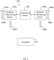
FIGURE 1 illustrates a network configured in accordance with an embodiment of the invention. -
FIGURE 2 illustrates a computer configured in accordance with an embodiment of the invention. -
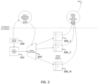
FIGURE 3 illustrates hardware based and software based operations performed in accordance with an embodiment of the invention. -
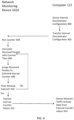
FIGURE 4 illustrates processing operations associated with an embodiment of the invention. - Like reference numerals refer to corresponding parts throughout the several views of the drawings.
-
FIG. 1 illustrates asystem 100 for network monitoring and network analysis, in accordance with an embodiment of the invention. Thesystem 100 includesnetwork monitoring devices 102A-102N on the ingress side of a monitoreddevice 106 andnetwork monitoring devices 106A-106N on the egress side of the monitoreddevice 106. The network traffic that is monitored and analyzed by the network monitoring devices 102 may enter the network monitoring devices 102 throughinterfaces 104A-104N (orinterfaces 108A-108N fornetwork monitoring devices 106A-106N). After monitoring and analysis by the network monitoring devices, the network traffic may exit the devices through the interfaces if the interfaces are bidirectional, or through other interfaces (not shown) if the interfaces are unidirectional. Each of the devices may have a large number of high-capacity interfaces, such as 32 10-Gigabit network interfaces. -
U.S. Patent 9,407,518 - The
network monitoring devices 102A-102N, 106A-106N use hardware counters to collect information on network traffic. The data from the counters is periodically transferred tocomputer 112 for evaluation under software control to generate network traffic activity data. - Thus, the disclosed invention decouples the hardware based real-time data collection performed by the
network monitoring devices 102A-102N, 106A-106N from the compression, analysis, and presentation performed oncomputer 112. This results in a significant cost savings because specialized hardware is not required at each port. Instead, a collection of counters, commonly available on a packet switch, are used for real-time data capture. The captured data is subsequently analyzed by software running oncomputer 112. This cost advantage can be realized across any programmable pipeline hardware that supports the disclosed hardware real-time constructs. -
Figure 2 illustrates acomputer 112 that may be used in accordance with an embodiment of the invention. Thecomputer 112 may include aprocessor 210 connected to input/output devices 212 via abus 214. Anetwork interface circuit 216 is also connected to thebus 214 to provide connectivity to the network hosting the devices ofFigure 1 . Amemory 220 is also connected to thebus 214. Thememory 220 stores instructions executed by theprocessor 210. In one embodiment, thememory 220 stores an intervaldiscriminator module 222. - The
interval discriminator module 222 associates counter values with an actual time of day. Counters available in a network monitoring device typically do not have enough bits to express a date and time. Therefore, theinterval discriminator module 222 is used to associate counter time snippets to an actual time of day. - The,
interval discriminator module 222 also has instructions executed byprocessor 210 to derive an interval discriminator configuration. As discussed below, the interval discriminator configuration is a set of rules that result in the assignment of a packet with a given counter value to a selected interval counter of a set of interval counters. -
Memory 220 also stores aninterval metric module 224. Theinterval metric module 224 includes instructions executed byprocessor 210 to collect values from the set of interval counters to generate network traffic activity data. In one embodiment, the network traffic data includes a maximum data rate in milliseconds, a minimum data rate in milliseconds, a data rate standard deviation, a time measurement of data rate over a pre-set threshold and a time measurement of data rate below a pre-set threshold. The network traffic activity data may also include individual flow data. -
Figure 3 illustrates software based processing performed by theinterval discriminator module 222 and theinterval metrics module 224 ofcomputer 112. The remaining components in the figure are hardware components in thenetwork monitoring devices 102A-102N, 106A-106N. A System Counter 300 is a hardware counter that increments automatically as time passes. This counter is synchronized to an external time source. - Timestamping Logic 302 associates the current value of the System Counter 300 with the instant of arrival of an ingress packet. The Interval Discriminator 304 considers the timestamp that was associated with the incoming packet and decides which measurement interval the packet should be assigned.
-
Figure 3 also illustrates Interval Counter Tables 306_1 through 306_N. These tables count the number of packets sent to a designated interval counter. These tables could be arranged separately or combined into a large single table that also has an index to allow a specific interval's accounting to the accessed. - Interval Discriminator Maintenance Process of
interval discriminator module 222 understands the relationship between the Time Reference and the actual Time of Day. In this way, it can identify which ranges of timestamp belong to which measurement interval. This information is programmed into the Interval Discriminator prior to that instant in time, such that the proper Interval Counter Table will be selected for each packet as it arrives. - Interval Counter Table Maintenance Process of interval
metric module 224 evacuates the counters and prepares the Interval Counter Table for reuse. It then processes the counters for compression, analysis and presentation. -
Figure 4 illustrates processing operations associated with the invention. Theinterval discriminator module 222 derives an interval discriminator configuration 400 and then transfers the interval discriminator configuration 402 tonetwork monitoring device 102A. TheSystem Counter 300 of thenetwork monitoring device 102A runs 402. TheTime Stamping Logic 302 associates received packets with a counter time 406. TheInterval Discriminator 304 assigns received packets to a selected interval counter 408 (i.e., one of Interval Counters 306_1 through 306_N). It is then determined whether the Time Window defined by the Interval Discriminator Configuration is expired 410. If not (410 - No), control returns to block 406. If so (410 - Yes), the Interval Counter Values 412 are transferred to theInterval Metric Module 224 ofcomputer 112. TheInterval Metric Module 224 derives network traffic activity data from the Interval Counter values 414. - The invention is more fully appreciated with a specific example. Assume that the
System Counter 300 is 32-bits wide and has nanosecond resolution. Of course, other dimensions could be used. The user desires to detect traffic bursts using 100 millisecond measurement intervals. Assume that the System Counter is synchronized such that it has value 0 at the beginning of the first measurement interval. Of course, another starting point could be used. Assume that the Interval Counter Tables 306_1 through 306_N are all available for use, and thus begin incrementing the counters in the table associated with index 0 at the beginning of the first measurement interval. If 10 Interval Counter Tables are used, this allows for 1 second to elapse before the tables would be recycled. - To prepare the
Interval Discriminator 304 for the upcoming second of measurements, 10 rules (corresponding to the 10 tables) must be configured by theInterval Discriminator Module 222. Table 1 is an example of such rules.Table 1 Rule Index Starting System Counter (nanoseconds) Ending System Counter (nanoseconds) Interval Counter Table Index 0 0x 0000 0000 0x 05F5 E0FF 0 1 0x 05F5 E100 0x OBEB C1FF 1 2 0x OBEB C200 0x 11E1 A2FF 2 3 0x 11E1 A300 0x 17D7 83FF 3 4 0x 17D7 8400 0x 1DCD 64FF 4 5 0x 1DCD 6500 0x 23C3 45FF 5 6 0x 23C3 4600 0x 29B9 26FF 6 7 0x 29B9 2700 0x 2FAF 07FF 7 8 0x 2FAF 0800 0x 35A4 E8FF 8 9 0x 35A4 E900 0x 3B9A C9FF 9 - The
Interval Discriminator Module 222 passes the Table to theinterval discriminator 304. Now, when the packets arrive with an associated timestamp that falls within this first second of time, the real time domain of the system has an Interval Counter Table Index assigned. This assigned index is used to direct the measurements taken on this packet to be accounted for in that table associated with that index. - As the
System Counter 300 increments past the range in a specific rule (call it rule N) in theInterval Discriminator 304, the Interval Counter Table associated with that same rule is evacuated by theInterval Metrics Module 224. - Sometime after, but before 900 milliseconds beyond rule N's range has elapsed, its range will be redefined to now bracket the next 100 millisecond interval, and so on. Always keeping ahead of the
System Counter 300 and wrapping as required when rolls-over occurs. - The evacuated Interval Counter Table contents are accumulated in the
Interval Metrics Module 224. TheInterval Metrics Module 224 quantifies traffic bursts in terms of when they occurred, how long they persisted, their magnitude, and other details describing the origin of the burst inducing communication. - In one embodiment, the network traffic data includes a maximum data rate per interval (e.g., per 100 milliseconds), a minimum data rate per interval, a data rate standard deviation per interval, a time measurement of data rate over a pre-set threshold per interval and a time measurement of data rate below a pre-set threshold per interval. The network traffic activity data may also include individual flow data.
- An embodiment of the present invention relates to a computer storage product with a computer readable storage medium having computer code thereon for performing various computer-implemented operations. The media and computer code may be those specially designed and constructed for the purposes of the present invention, or they may be of the kind well known and available to those having skill in the computer software arts. Examples of computer-readable media include, but are not limited to: magnetic media such as hard disks, floppy disks, and magnetic tape; optical media such as CD-ROMs, DVDs and holographic devices; magneto-optical media; and hardware devices that are specially configured to store and execute program code, such as application-specific integrated circuits ("ASICs"), programmable logic devices ("PLDs") and ROM and RAM devices. Examples of computer code include machine code, such as produced by a compiler, and files containing higher-level code that are executed by a computer using an interpreter. For example, an embodiment of the invention may be implemented using JAVA®, C++, or other objectoriented programming language and development tools. Another embodiment of the invention may be implemented in hardwired circuitry in place of, or in combination with, machine-executable software instructions.
- The foregoing description, for purposes of explanation, used specific nomenclature to provide a thorough understanding of the invention. However, it will be apparent to one skilled in the art that specific details are not required in order to practice the invention. Thus, the foregoing descriptions of specific embodiments of the invention are presented for purposes of illustration and description. It is intended that the following claims define the scope of the invention.
Claims (9)
- A system, comprising:a packet switch for routing network traffic, the packet switch including a system counter (300) to increment a counter time in predetermined time segments, time stamping logic (302) to associate each received packet with the counter time at an instant of arrival of each received packet, and an interval discriminator (304) with a set of rules to assign each received packet to a selected interval counter (306) of a set of interval counters (306_1-306_N) based upon the counter time associated with each received packet; anda computer (112) connected to the packet switch, the computer including a memory with instructions executed by a processor to:associate the counter time of each received packet with a time of day, andcollect the counter time of each received packet from the set of interval counters to generate network traffic activity data.
- The system of claim 1 wherein the network traffic activity data includes a maximum data rate.
- The system of claim 1 wherein the network traffic activity data includes a minimum data rate.
- The system of claim 1 wherein the network traffic activity data includes a data rate standard deviation.
- The system of claim 1 wherein the network traffic activity data includes a time measurement of data rate over a pre-set threshold.
- The system of claim 1 wherein the network traffic activity data includes a time measurement of data rate below a pre-set threshold.
- The system of claim 1 wherein the network traffic activity data includes individual flow data.
- The system of claim 1 wherein the computer includes instructions executed by the processor to derive an interval discriminator configuration, wherein the interval discrimination configuration is the set of rules.
- The system of claim 1, wherein the interval counter from the set of interval counters stores counter times insufficient to express a time and date.
Applications Claiming Priority (2)
| Application Number | Priority Date | Filing Date | Title |
|---|---|---|---|
| US16/993,961 US11528203B2 (en) | 2020-08-14 | 2020-08-14 | Packet switch with hardware interval counters and associated computer to generate network traffic activity data |
| PCT/US2021/045416 WO2022035878A1 (en) | 2020-08-14 | 2021-08-10 | Packet switch with hardware interval counters and associated computer to generate network traffic activity data |
Publications (3)
| Publication Number | Publication Date |
|---|---|
| EP4208993A1 EP4208993A1 (en) | 2023-07-12 |
| EP4208993A4 EP4208993A4 (en) | 2024-07-31 |
| EP4208993B1 true EP4208993B1 (en) | 2025-07-02 |
Family
ID=80223448
Family Applications (1)
| Application Number | Title | Priority Date | Filing Date |
|---|---|---|---|
| EP21856584.4A Active EP4208993B1 (en) | 2020-08-14 | 2021-08-10 | Packet switch with hardware interval counters and associated computer to generate network traffic activity data |
Country Status (5)
| Country | Link |
|---|---|
| US (1) | US11528203B2 (en) |
| EP (1) | EP4208993B1 (en) |
| DK (1) | DK4208993T3 (en) |
| ES (1) | ES3042354T3 (en) |
| WO (1) | WO2022035878A1 (en) |
Family Cites Families (14)
| Publication number | Priority date | Publication date | Assignee | Title |
|---|---|---|---|---|
| US7606575B2 (en) * | 1988-08-04 | 2009-10-20 | Broadcom Corporation | Remote radio data communication system with data rate switching |
| US5179557A (en) * | 1989-07-04 | 1993-01-12 | Kabushiki Kaisha Toshiba | Data packet communication system in which data packet transmittal is prioritized with queues having respective assigned priorities and frequency weighted counting of queue wait time |
| US7206861B1 (en) * | 2002-07-29 | 2007-04-17 | Juniper Networks, Inc. | Network traffic distribution across parallel paths |
| US8213323B1 (en) * | 2003-12-18 | 2012-07-03 | Sprint Communications Company L.P. | System and method for network performance monitoring |
| US8015294B2 (en) * | 2006-08-22 | 2011-09-06 | Embarq Holdings Company, LP | Pin-hole firewall for communicating data packets on a packet network |
| US7889660B2 (en) * | 2006-08-22 | 2011-02-15 | Embarq Holdings Company, Llc | System and method for synchronizing counters on an asynchronous packet communications network |
| US9479341B2 (en) * | 2006-08-22 | 2016-10-25 | Centurylink Intellectual Property Llc | System and method for initiating diagnostics on a packet network node |
| US8194555B2 (en) * | 2006-08-22 | 2012-06-05 | Embarq Holdings Company, Llc | System and method for using distributed network performance information tables to manage network communications |
| US8140884B2 (en) * | 2008-07-18 | 2012-03-20 | Verisign, Inc. | Efficient time-based memory counters |
| US8248926B2 (en) * | 2010-05-11 | 2012-08-21 | Ixia | Packet rate detection apparatus and method |
| US9800487B2 (en) * | 2011-09-19 | 2017-10-24 | Telecom Italia S.P.A. | Measurement on a data flow in a communication network |
| US8848741B2 (en) * | 2012-06-21 | 2014-09-30 | Breakingpoint Systems, Inc. | High-speed CLD-based TCP segmentation offload |
| EP3223526B1 (en) * | 2014-11-20 | 2019-01-30 | Panasonic Intellectual Property Corporation of America | Transmission method, reception method, transmission device, and reception device |
| JP6115589B2 (en) * | 2015-06-18 | 2017-04-19 | カシオ計算機株式会社 | Satellite radio wave receiver, electronic clock, date and time information acquisition method and program |
-
2020
- 2020-08-14 US US16/993,961 patent/US11528203B2/en active Active
-
2021
- 2021-08-10 DK DK21856584.4T patent/DK4208993T3/en active
- 2021-08-10 EP EP21856584.4A patent/EP4208993B1/en active Active
- 2021-08-10 ES ES21856584T patent/ES3042354T3/en active Active
- 2021-08-10 WO PCT/US2021/045416 patent/WO2022035878A1/en not_active Ceased
Also Published As
| Publication number | Publication date |
|---|---|
| US11528203B2 (en) | 2022-12-13 |
| US20220052934A1 (en) | 2022-02-17 |
| EP4208993A1 (en) | 2023-07-12 |
| WO2022035878A1 (en) | 2022-02-17 |
| ES3042354T3 (en) | 2025-11-20 |
| DK4208993T3 (en) | 2025-09-29 |
| EP4208993A4 (en) | 2024-07-31 |
Similar Documents
| Publication | Publication Date | Title |
|---|---|---|
| US20210042270A1 (en) | Alarm log compression method, apparatus, and system, and storage medium | |
| US8432827B2 (en) | Arrangement for utilization rate display and methods thereof | |
| JP2910973B2 (en) | Information collection method, data communication network control system, and data communication network control method | |
| EP3197100B1 (en) | Multi cause correlation in wireless protocols | |
| CN102870377A (en) | Monitoring method and device for virtual port | |
| EP2637362B1 (en) | Bus participant device for connection to a line-redundant, serial data bus and method for controlling the communication of a bus participant with a line-redundant, serial data bus | |
| CN111103864B (en) | Method and device suitable for train control center test | |
| JPH07221760A (en) | Data capture device | |
| US20100157812A1 (en) | Method and apparatus for asynchronous alarm correlation | |
| US20230261940A1 (en) | Network Intention Monitoring Method, Network Intention Monitoring System, and Storage Medium | |
| CN112262554B (en) | Packet Programmable Streaming Telemetry Profiling and Analysis | |
| CN109639503A (en) | A kind of exception message retrospect implementation method based on Substation Process layer network device | |
| KR100861592B1 (en) | Method and apparatus for managing fault in customer network management system | |
| CN109831462A (en) | A kind of method for detecting virus and device | |
| CN112333163A (en) | Inter-container flow monitoring method and flow monitoring management system | |
| US9917747B2 (en) | Problem detection in a distributed digital network through distributed packet analysis | |
| US7738403B2 (en) | Method for determining the operations performed on packets by a network device | |
| US11552870B2 (en) | Dynamic profile guided network telemetry configuration | |
| US20060167973A1 (en) | Database system monitoring method without connecting the database system | |
| US11528203B2 (en) | Packet switch with hardware interval counters and associated computer to generate network traffic activity data | |
| US20060077905A1 (en) | Measure and recording of traffic parameters in data transmission networks | |
| CN107666417B (en) | Method for realizing IPFIX random sampling | |
| US20080123675A1 (en) | Data transmission apparatus and data transmission method | |
| Peng et al. | Design and implementation of network instruction detection system based on snort and NTOP | |
| CN117336211A (en) | Network bandwidth monitoring method, device, equipment, medium and program product |
Legal Events
| Date | Code | Title | Description |
|---|---|---|---|
| STAA | Information on the status of an ep patent application or granted ep patent |
Free format text: STATUS: THE INTERNATIONAL PUBLICATION HAS BEEN MADE |
|
| PUAI | Public reference made under article 153(3) epc to a published international application that has entered the european phase |
Free format text: ORIGINAL CODE: 0009012 |
|
| STAA | Information on the status of an ep patent application or granted ep patent |
Free format text: STATUS: REQUEST FOR EXAMINATION WAS MADE |
|
| 17P | Request for examination filed |
Effective date: 20230313 |
|
| AK | Designated contracting states |
Kind code of ref document: A1 Designated state(s): AL AT BE BG CH CY CZ DE DK EE ES FI FR GB GR HR HU IE IS IT LI LT LU LV MC MK MT NL NO PL PT RO RS SE SI SK SM TR |
|
| DAV | Request for validation of the european patent (deleted) | ||
| DAX | Request for extension of the european patent (deleted) | ||
| REG | Reference to a national code |
Ref country code: DE Free format text: PREVIOUS MAIN CLASS: H04L0043000000 Ipc: H04L0043067000 Ref country code: DE Ref legal event code: R079 Ref document number: 602021033545 Country of ref document: DE Free format text: PREVIOUS MAIN CLASS: H04L0043000000 Ipc: H04L0043067000 |
|
| A4 | Supplementary search report drawn up and despatched |
Effective date: 20240702 |
|
| RIC1 | Information provided on ipc code assigned before grant |
Ipc: H04L 43/12 20220101ALI20240626BHEP Ipc: H04L 43/0894 20220101ALI20240626BHEP Ipc: H04L 43/067 20220101AFI20240626BHEP |
|
| GRAP | Despatch of communication of intention to grant a patent |
Free format text: ORIGINAL CODE: EPIDOSNIGR1 |
|
| STAA | Information on the status of an ep patent application or granted ep patent |
Free format text: STATUS: GRANT OF PATENT IS INTENDED |
|
| INTG | Intention to grant announced |
Effective date: 20250129 |
|
| RAP3 | Party data changed (applicant data changed or rights of an application transferred) |
Owner name: CPACKET NETWORKS INC. |
|
| GRAS | Grant fee paid |
Free format text: ORIGINAL CODE: EPIDOSNIGR3 |
|
| P01 | Opt-out of the competence of the unified patent court (upc) registered |
Free format text: CASE NUMBER: APP_19205/2025 Effective date: 20250422 |
|
| GRAA | (expected) grant |
Free format text: ORIGINAL CODE: 0009210 |
|
| STAA | Information on the status of an ep patent application or granted ep patent |
Free format text: STATUS: THE PATENT HAS BEEN GRANTED |
|
| AK | Designated contracting states |
Kind code of ref document: B1 Designated state(s): AL AT BE BG CH CY CZ DE DK EE ES FI FR GB GR HR HU IE IS IT LI LT LU LV MC MK MT NL NO PL PT RO RS SE SI SK SM TR |
|
| REG | Reference to a national code |
Ref country code: GB Ref legal event code: FG4D |
|
| REG | Reference to a national code |
Ref country code: CH Ref legal event code: EP |
|
| REG | Reference to a national code |
Ref country code: DE Ref legal event code: R096 Ref document number: 602021033545 Country of ref document: DE |
|
| REG | Reference to a national code |
Ref country code: IE Ref legal event code: FG4D |
|
| REG | Reference to a national code |
Ref country code: DK Ref legal event code: T3 Effective date: 20250925 |
|
| PGFP | Annual fee paid to national office [announced via postgrant information from national office to epo] |
Ref country code: DE Payment date: 20250923 Year of fee payment: 5 Ref country code: DK Payment date: 20250930 Year of fee payment: 5 |
|
| PGFP | Annual fee paid to national office [announced via postgrant information from national office to epo] |
Ref country code: GB Payment date: 20250916 Year of fee payment: 5 |
|
| PGFP | Annual fee paid to national office [announced via postgrant information from national office to epo] |
Ref country code: FR Payment date: 20250918 Year of fee payment: 5 Ref country code: AT Payment date: 20251020 Year of fee payment: 5 |
|
| REG | Reference to a national code |
Ref country code: NL Ref legal event code: MP Effective date: 20250702 |
|
| REG | Reference to a national code |
Ref country code: ES Ref legal event code: FG2A Ref document number: 3042354 Country of ref document: ES Kind code of ref document: T3 Effective date: 20251120 |
|
| PG25 | Lapsed in a contracting state [announced via postgrant information from national office to epo] |
Ref country code: PT Free format text: LAPSE BECAUSE OF FAILURE TO SUBMIT A TRANSLATION OF THE DESCRIPTION OR TO PAY THE FEE WITHIN THE PRESCRIBED TIME-LIMIT Effective date: 20251103 |
|
| PG25 | Lapsed in a contracting state [announced via postgrant information from national office to epo] |
Ref country code: NL Free format text: LAPSE BECAUSE OF FAILURE TO SUBMIT A TRANSLATION OF THE DESCRIPTION OR TO PAY THE FEE WITHIN THE PRESCRIBED TIME-LIMIT Effective date: 20250702 |
|
| REG | Reference to a national code |
Ref country code: AT Ref legal event code: MK05 Ref document number: 1810574 Country of ref document: AT Kind code of ref document: T Effective date: 20250702 |
|
| PG25 | Lapsed in a contracting state [announced via postgrant information from national office to epo] |
Ref country code: IS Free format text: LAPSE BECAUSE OF FAILURE TO SUBMIT A TRANSLATION OF THE DESCRIPTION OR TO PAY THE FEE WITHIN THE PRESCRIBED TIME-LIMIT Effective date: 20251102 |
|
| PG25 | Lapsed in a contracting state [announced via postgrant information from national office to epo] |
Ref country code: NO Free format text: LAPSE BECAUSE OF FAILURE TO SUBMIT A TRANSLATION OF THE DESCRIPTION OR TO PAY THE FEE WITHIN THE PRESCRIBED TIME-LIMIT Effective date: 20251002 |
|
| REG | Reference to a national code |
Ref country code: LT Ref legal event code: MG9D |
|
| PG25 | Lapsed in a contracting state [announced via postgrant information from national office to epo] |
Ref country code: AT Free format text: LAPSE BECAUSE OF FAILURE TO SUBMIT A TRANSLATION OF THE DESCRIPTION OR TO PAY THE FEE WITHIN THE PRESCRIBED TIME-LIMIT Effective date: 20250702 |
|
| PG25 | Lapsed in a contracting state [announced via postgrant information from national office to epo] |
Ref country code: FI Free format text: LAPSE BECAUSE OF FAILURE TO SUBMIT A TRANSLATION OF THE DESCRIPTION OR TO PAY THE FEE WITHIN THE PRESCRIBED TIME-LIMIT Effective date: 20250702 |
|
| PGFP | Annual fee paid to national office [announced via postgrant information from national office to epo] |
Ref country code: IT Payment date: 20251022 Year of fee payment: 5 |
|
| PG25 | Lapsed in a contracting state [announced via postgrant information from national office to epo] |
Ref country code: HR Free format text: LAPSE BECAUSE OF FAILURE TO SUBMIT A TRANSLATION OF THE DESCRIPTION OR TO PAY THE FEE WITHIN THE PRESCRIBED TIME-LIMIT Effective date: 20250702 |
|
| PG25 | Lapsed in a contracting state [announced via postgrant information from national office to epo] |
Ref country code: GR Free format text: LAPSE BECAUSE OF FAILURE TO SUBMIT A TRANSLATION OF THE DESCRIPTION OR TO PAY THE FEE WITHIN THE PRESCRIBED TIME-LIMIT Effective date: 20251003 |
|
| PG25 | Lapsed in a contracting state [announced via postgrant information from national office to epo] |
Ref country code: CZ Free format text: LAPSE BECAUSE OF FAILURE TO SUBMIT A TRANSLATION OF THE DESCRIPTION OR TO PAY THE FEE WITHIN THE PRESCRIBED TIME-LIMIT Effective date: 20250702 Ref country code: SE Free format text: LAPSE BECAUSE OF FAILURE TO SUBMIT A TRANSLATION OF THE DESCRIPTION OR TO PAY THE FEE WITHIN THE PRESCRIBED TIME-LIMIT Effective date: 20250702 |
|
| PG25 | Lapsed in a contracting state [announced via postgrant information from national office to epo] |
Ref country code: LV Free format text: LAPSE BECAUSE OF FAILURE TO SUBMIT A TRANSLATION OF THE DESCRIPTION OR TO PAY THE FEE WITHIN THE PRESCRIBED TIME-LIMIT Effective date: 20250702 |
|
| PG25 | Lapsed in a contracting state [announced via postgrant information from national office to epo] |
Ref country code: BG Free format text: LAPSE BECAUSE OF FAILURE TO SUBMIT A TRANSLATION OF THE DESCRIPTION OR TO PAY THE FEE WITHIN THE PRESCRIBED TIME-LIMIT Effective date: 20250702 Ref country code: PL Free format text: LAPSE BECAUSE OF FAILURE TO SUBMIT A TRANSLATION OF THE DESCRIPTION OR TO PAY THE FEE WITHIN THE PRESCRIBED TIME-LIMIT Effective date: 20250702 |
|
| PG25 | Lapsed in a contracting state [announced via postgrant information from national office to epo] |
Ref country code: RS Free format text: LAPSE BECAUSE OF FAILURE TO SUBMIT A TRANSLATION OF THE DESCRIPTION OR TO PAY THE FEE WITHIN THE PRESCRIBED TIME-LIMIT Effective date: 20251002 |
|
| PGFP | Annual fee paid to national office [announced via postgrant information from national office to epo] |
Ref country code: ES Payment date: 20251002 Year of fee payment: 5 |
|
| PG25 | Lapsed in a contracting state [announced via postgrant information from national office to epo] |
Ref country code: RO Free format text: LAPSE BECAUSE OF FAILURE TO SUBMIT A TRANSLATION OF THE DESCRIPTION OR TO PAY THE FEE WITHIN THE PRESCRIBED TIME-LIMIT Effective date: 20250702 |
|
| REG | Reference to a national code |
Ref country code: CH Ref legal event code: H13 Free format text: ST27 STATUS EVENT CODE: U-0-0-H10-H13 (AS PROVIDED BY THE NATIONAL OFFICE) Effective date: 20260324 |
|
| PG25 | Lapsed in a contracting state [announced via postgrant information from national office to epo] |
Ref country code: SM Free format text: LAPSE BECAUSE OF FAILURE TO SUBMIT A TRANSLATION OF THE DESCRIPTION OR TO PAY THE FEE WITHIN THE PRESCRIBED TIME-LIMIT Effective date: 20250702 |
|
| REG | Reference to a national code |
Ref country code: DE Ref legal event code: R097 Ref document number: 602021033545 Country of ref document: DE |
|
| PG25 | Lapsed in a contracting state [announced via postgrant information from national office to epo] |
Ref country code: LU Free format text: LAPSE BECAUSE OF NON-PAYMENT OF DUE FEES Effective date: 20250810 |
|
| PG25 | Lapsed in a contracting state [announced via postgrant information from national office to epo] |
Ref country code: CH Free format text: LAPSE BECAUSE OF NON-PAYMENT OF DUE FEES Effective date: 20250831 |
|
| PG25 | Lapsed in a contracting state [announced via postgrant information from national office to epo] |
Ref country code: SK Free format text: LAPSE BECAUSE OF FAILURE TO SUBMIT A TRANSLATION OF THE DESCRIPTION OR TO PAY THE FEE WITHIN THE PRESCRIBED TIME-LIMIT Effective date: 20250702 Ref country code: EE Free format text: LAPSE BECAUSE OF FAILURE TO SUBMIT A TRANSLATION OF THE DESCRIPTION OR TO PAY THE FEE WITHIN THE PRESCRIBED TIME-LIMIT Effective date: 20250702 |
|
| REG | Reference to a national code |
Ref country code: BE Ref legal event code: MM Effective date: 20250831 |
|
| PLBE | No opposition filed within time limit |
Free format text: ORIGINAL CODE: 0009261 |
|
| STAA | Information on the status of an ep patent application or granted ep patent |
Free format text: STATUS: NO OPPOSITION FILED WITHIN TIME LIMIT |
|
| REG | Reference to a national code |
Ref country code: CH Ref legal event code: L10 Free format text: ST27 STATUS EVENT CODE: U-0-0-L10-L00 (AS PROVIDED BY THE NATIONAL OFFICE) Effective date: 20260518 |
|
| 26N | No opposition filed |
Effective date: 20260407 |
|
| PG25 | Lapsed in a contracting state [announced via postgrant information from national office to epo] |
Ref country code: MC Free format text: LAPSE BECAUSE OF FAILURE TO SUBMIT A TRANSLATION OF THE DESCRIPTION OR TO PAY THE FEE WITHIN THE PRESCRIBED TIME-LIMIT Effective date: 20250702 Ref country code: LT Free format text: LAPSE BECAUSE OF FAILURE TO SUBMIT A TRANSLATION OF THE DESCRIPTION OR TO PAY THE FEE WITHIN THE PRESCRIBED TIME-LIMIT Effective date: 20250702 |
|
| PG25 | Lapsed in a contracting state [announced via postgrant information from national office to epo] |
Ref country code: IE Free format text: LAPSE BECAUSE OF NON-PAYMENT OF DUE FEES Effective date: 20250810 Ref country code: BE Free format text: LAPSE BECAUSE OF NON-PAYMENT OF DUE FEES Effective date: 20250831 |