EP4208774B1 - Method for reducing primary and backup storage - Google Patents
Method for reducing primary and backup storage Download PDFInfo
- Publication number
- EP4208774B1 EP4208774B1 EP21723869.0A EP21723869A EP4208774B1 EP 4208774 B1 EP4208774 B1 EP 4208774B1 EP 21723869 A EP21723869 A EP 21723869A EP 4208774 B1 EP4208774 B1 EP 4208774B1
- Authority
- EP
- European Patent Office
- Prior art keywords
- data storage
- file
- data
- files
- similar files
- Prior art date
- Legal status (The legal status is an assumption and is not a legal conclusion. Google has not performed a legal analysis and makes no representation as to the accuracy of the status listed.)
- Active
Links
Images




Classifications
-
- G—PHYSICS
- G06—COMPUTING OR CALCULATING; COUNTING
- G06F—ELECTRIC DIGITAL DATA PROCESSING
- G06F3/00—Input arrangements for transferring data to be processed into a form capable of being handled by the computer; Output arrangements for transferring data from processing unit to output unit, e.g. interface arrangements
- G06F3/06—Digital input from, or digital output to, record carriers, e.g. RAID, emulated record carriers or networked record carriers
- G06F3/0601—Interfaces specially adapted for storage systems
- G06F3/0602—Interfaces specially adapted for storage systems specifically adapted to achieve a particular effect
- G06F3/0608—Saving storage space on storage systems
-
- G—PHYSICS
- G06—COMPUTING OR CALCULATING; COUNTING
- G06F—ELECTRIC DIGITAL DATA PROCESSING
- G06F16/00—Information retrieval; Database structures therefor; File system structures therefor
- G06F16/10—File systems; File servers
- G06F16/13—File access structures, e.g. distributed indices
- G06F16/137—Hash-based
-
- G—PHYSICS
- G06—COMPUTING OR CALCULATING; COUNTING
- G06F—ELECTRIC DIGITAL DATA PROCESSING
- G06F16/00—Information retrieval; Database structures therefor; File system structures therefor
- G06F16/10—File systems; File servers
- G06F16/17—Details of further file system functions
- G06F16/1727—Details of free space management performed by the file system
-
- G—PHYSICS
- G06—COMPUTING OR CALCULATING; COUNTING
- G06F—ELECTRIC DIGITAL DATA PROCESSING
- G06F16/00—Information retrieval; Database structures therefor; File system structures therefor
- G06F16/10—File systems; File servers
- G06F16/17—Details of further file system functions
- G06F16/174—Redundancy elimination performed by the file system
- G06F16/1748—De-duplication implemented within the file system, e.g. based on file segments
- G06F16/1752—De-duplication implemented within the file system, e.g. based on file segments based on file chunks
-
- G—PHYSICS
- G06—COMPUTING OR CALCULATING; COUNTING
- G06F—ELECTRIC DIGITAL DATA PROCESSING
- G06F3/00—Input arrangements for transferring data to be processed into a form capable of being handled by the computer; Output arrangements for transferring data from processing unit to output unit, e.g. interface arrangements
- G06F3/06—Digital input from, or digital output to, record carriers, e.g. RAID, emulated record carriers or networked record carriers
- G06F3/0601—Interfaces specially adapted for storage systems
- G06F3/0628—Interfaces specially adapted for storage systems making use of a particular technique
- G06F3/0646—Horizontal data movement in storage systems, i.e. moving data in between storage devices or systems
- G06F3/0647—Migration mechanisms
-
- G—PHYSICS
- G06—COMPUTING OR CALCULATING; COUNTING
- G06F—ELECTRIC DIGITAL DATA PROCESSING
- G06F3/00—Input arrangements for transferring data to be processed into a form capable of being handled by the computer; Output arrangements for transferring data from processing unit to output unit, e.g. interface arrangements
- G06F3/06—Digital input from, or digital output to, record carriers, e.g. RAID, emulated record carriers or networked record carriers
- G06F3/0601—Interfaces specially adapted for storage systems
- G06F3/0668—Interfaces specially adapted for storage systems adopting a particular infrastructure
- G06F3/067—Distributed or networked storage systems, e.g. storage area networks [SAN], network attached storage [NAS]
-
- H—ELECTRICITY
- H03—ELECTRONIC CIRCUITRY
- H03M—CODING; DECODING; CODE CONVERSION IN GENERAL
- H03M7/00—Conversion of a code where information is represented by a given sequence or number of digits to a code where the same, similar or subset of information is represented by a different sequence or number of digits
- H03M7/30—Compression; Expansion; Suppression of unnecessary data, e.g. redundancy reduction
- H03M7/3068—Precoding preceding compression, e.g. Burrows-Wheeler transformation
- H03M7/3077—Sorting
-
- H—ELECTRICITY
- H03—ELECTRONIC CIRCUITRY
- H03M—CODING; DECODING; CODE CONVERSION IN GENERAL
- H03M7/00—Conversion of a code where information is represented by a given sequence or number of digits to a code where the same, similar or subset of information is represented by a different sequence or number of digits
- H03M7/30—Compression; Expansion; Suppression of unnecessary data, e.g. redundancy reduction
- H03M7/3084—Compression; Expansion; Suppression of unnecessary data, e.g. redundancy reduction using adaptive string matching, e.g. the Lempel-Ziv method
- H03M7/3091—Data deduplication
-
- G—PHYSICS
- G06—COMPUTING OR CALCULATING; COUNTING
- G06F—ELECTRIC DIGITAL DATA PROCESSING
- G06F3/00—Input arrangements for transferring data to be processed into a form capable of being handled by the computer; Output arrangements for transferring data from processing unit to output unit, e.g. interface arrangements
- G06F3/06—Digital input from, or digital output to, record carriers, e.g. RAID, emulated record carriers or networked record carriers
- G06F3/0601—Interfaces specially adapted for storage systems
- G06F3/0628—Interfaces specially adapted for storage systems making use of a particular technique
- G06F3/0638—Organizing or formatting or addressing of data
- G06F3/064—Management of blocks
- G06F3/0641—De-duplication techniques
Definitions
- the present disclosure relates generally to the field of data management; and more specifically, to a method, a data management device and a data storage system for reducing primary and backup storage.
- data related to an entity is stored in terms of multiple data files and data objects which are further stored on various physical machines, virtual machines located on different hosts (e.g., VMware, Hyper-V, etc.) and data centres (e.g., network attached servers (NAS)).
- NAS network attached servers
- data files and data objects there may be duplicity of data files and similarity (i.e., partially same data) may also exist among the multiple data files, while saving the data related to the entire enterprise or the organisation.
- Data de-duplication may be defined as a technique to eliminate duplicate copies of repeating data.
- Storage reduction methods can be applied to both a primary storage cluster and a secondary (backup) storage cluster.
- a secondary (backup) storage cluster In case of use of the secondary storage cluster, depending on the scalability of the secondary storage cluster and size of the data centre, more than one secondary storage cluster may be needed in order to protect one data centre.
- different backup layouts may be used to store the backed-up data, such as incremental block level, file level, and data de-duplication.
- data to be stored is either compressed and/or encrypted.
- the duplicate data files and the similar data files which may be stored on the same data centre, their backup layout is de-duplicated and hence, the de-duped data files may be stored in a backup repository with a partial efficiency.
- the backup layout with de-duplication reduces the backup storage capacity only for a specific data centre or partial of the specific data centre.
- there are limitations associated with the available methods such as the duplicate data files and the similar data files which may be stored on different data centres are not de-duped efficiently in the backup storage because of the secondary storage protection scope.
- US 10 303 797 B1 relates to clustering files in deduplication systems based on an estimate of similarity between files in a file system.
- US 2020/233752 A1 relates to a mostly unique file selection method for deduplication backup systems.
- the present disclosure provides a method for reducing primary as well as backup storage.
- the present disclosure further provides a data management device and a data storage system for reducing primary and backup storage.
- the present disclosure provides a solution to the existing problem of inefficiently and inadequately handling and reducing the primary storage as well as the backup storage.
- An aim of the present disclosure is to provide a solution that overcomes at least partially the problems encountered in prior art, and provide an improved method, a data management device and a data storage system for reducing primary as well as backup storage.
- the object of the present disclosure is achieved by the solutions provided in the enclosed independent claims.
- Advantageous implementations of the present disclosure are further defined in the dependent claims.
- an underlined number is employed to represent an item over which the underlined number is positioned or an item to which the underlined number is adjacent.
- a non-underlined number relates to an item identified by a line linking the non-underlined number to the item. When a number is non-underlined and accompanied by an associated arrow, the non-underlined number is used to identify a general item at which the arrow is pointing.
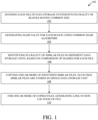
- the present disclosure provides a computer-implemented method (i.e., the method 100) of data management in a data storage system comprising a plurality of data storage units, the method 100 comprising:
- the method 100 improves an unstructured data management of an entire enterprise storage system.
- the method 100 includes collecting information of an unstructured data that may be stored on different sources of the entire enterprise storage, such as a data centre (e.g., network attached server (NAS)), a data object (e.g., Amazon S3), a virtual machine (VM), or a physical machine, etc.
- the information may be collected either periodically or as a "live update”.
- the collected information may be a native meta data with an additional synthetic data, for example, input or output temperature of a file.
- the method 100 comprises dividing each file in the data storage system into a plurality of blocks having a common size. For example, video file or an audio file is divided into the plurality of blocks while saving the video file or the audio file in the data storage system (e.g., a data centre, or a NAS).
- Each of the plurality of blocks is of the common size but has different data.
- the data storage system may have one or more data storage units (or devices), such as physical machines, virtual machines, data centres (or network attached servers), and the like.
- the data storage system represents a storage system of the entire enterprise storage or an organisation.
- the method 100 further comprises generating a hash value for each block using a common hash algorithm.
- the hash value for each block of the plurality of blocks is generated by use of the common hash algorithm.
- a secure hash algorithm 1 SHA-1
- the secure hash algorithm 1 may be defined as a cryptographic hash function which takes an input and generates a hash value of 160 bits in output.
- the method 100 further comprises identifying a plurality of similar files in different data storage units, based on a comparison of the hashes for each file.
- multiple video files or audio files may be stored on different data centres (or network attached servers), or physical machines or virtual machines.
- the hash (or the hash value) associated with each block of the plurality of blocks of each video file or the audio file is compared with each other.
- the plurality of similar files i.e., the files having each block of the plurality of blocks having same hashes or hash values
- the multiple video files or audio files may be identified as the plurality of similar files if 5 highest weak hashes stored per file are found as same.
- the method 100 further comprises copying one or more of the identified similar files, such that similar files are stored in a single data storage unit.
- the one or more of the identified similar files are copied in the single data storage unit (e.g., a centralised network attached server) in order to ease the de-duplication of the one or more of the identified similar files resulting into reduction of primary storage. This further results into an improved detection time of duplicate and similar files stored across the entire enterprise storage.
- the method 100 further comprises for one or more of the copied files, generating a link to a new location of the file.
- the one or more of the identified similar files which are stored (or copied) in the single data storage unit are termed as the one or more copied files.
- the link to the new location i.e., the centralised network attached server
- the link to the new location is provided as a stub in the source file, hence, results into reduction of primary storage as well as secondary storage.
- identifying the plurality of similar files includes collecting one or more hash values from each file in the data storage system and comparing the collected hash values.
- the plurality of similar files is identified by collecting one or more hash values (or the hashes) associated with the plurality of blocks of each file stored in the data storage system.
- the collected one or more hash values (or the hashes) associated with the plurality of blocks of each file that is stored in the data storage system are compared with each other.
- the method 100 further comprises collecting a predefined number of hash values from each file, wherein the collected hash values are the highest for each file. For comparison of the one or more hash values (or the hashes) associated with the plurality of blocks of each file, the predefined number of hash values from each file are collected.
- the collected hash values are the highest hash values stored per file.
- the plurality of similar files may be identified if 5 highest weak hashes (e.g., weak hash - 8bytes) stored per file are collected from one or more data storage systems and found as same on comparison with each other.
- the 5 highest weak hashes stored per file may be collected in various ways, for example, by use of primary storage, such as an application programming interface (API).
- API application programming interface
- identifying the plurality of similar files includes determining a percentage number of blocks in common and comparing the determined percentage to a minimum threshold value.
- the plurality of similar files is identified on the basis of the percentage number of blocks which are common in one or more files. Moreover, the percentage number of blocks common in one or more files are compared to the minimum threshold value. For example, a video file stored in the data storage system is divided into 3 blocks. Another video file stored in the data storage system is divided into 4 blocks. The first two blocks of the video file and the other video file are common in both the files. Therefore, the percentage number of blocks in common among the video file and the other video file may be approximately 57 percent. The percentage number of blocks in common (i.e., the 57%) is further compared with the minimum threshold value.
- copying the identified similar files comprises copying both files to a centralised data storage unit.
- the identified similar files are copied to the centralised data storage unit (e.g., a centralised network attached server) so that the identified similar files are de-duped by the centralised data storage unit with more ease resulting into reduction of primary storage as well as secondary storage.
- the storage (or backup) of similar files that were stored on different data storage units (or secondary storage cluster) can now be stored on the same data storage unit (or cluster) and by leveraging data de-duplication technique, the backup storage space (or the secondary storage space) may be reduced significantly.
- copying the similar files comprises selecting the data storage unit of one file as an optimal storage location, and copying one or more other similar files to the optimal storage location. For example, in case of two identified similar files, the data storage unit of a bigger file among the two identified similar files is considered as the optimal storage location and a smaller file among the two identified similar files is copied to the optimal storage location.
- the optimal storage location is selected to minimise the volume of data to be copied.
- the optimal storage location is selected in order to ease the data de-duplication of the volume of data to be copied to the optimal storage location.
- the centralised network attached server is selected as the optimal storage location in order to minimise the volume of data to be copied by use of the data de-duplication.
- the optimal storage location is selected based on an access speed or reliability of the data storage units. For example, in case of a sensitive or an important data, the selection of the optimal storage location is performed on the basis of the access speed or reliability of the data storage units. In case of the sensitive data, the identified similar files are copied to multiple data storage units rather than one data storage unit. In such a case, the access speed and reliability of the multiple data storage units is of primary concern due to protection level of the sensitive data.
- the data storage system is a network-based system.
- the data storage system is the network-based system, such as the centralised network attached server (NAS), or a cloud network which is linked with a network, for example, an internet.
- NAS centralised network attached server
- cloud network which is linked with a network, for example, an internet.
- the method 100 efficiently reduces the primary storage as well as the secondary storage space.
- the storage (or backup) of duplicate files and similar (i.e., partially the same) files that were stored on different data storage units (or secondary storage cluster) can now be stored on the same data storage unit (or cluster) and by leveraging data de-duplication technique, the backup storage space (or the secondary storage space) may be reduced significantly.
- the method 100 improves detection time of duplicate files and similar (i.e., partially the same) files across the entire enterprise storage.
- the collected information may be a native meta data with an additional synthetic data, for example, input or output temperature of a file may be obtained by calculating number of reads per file in the last 24 hours or any other synthetic information.
- the data management device 202 may be configured to run different type of queries and perform an analysis and supply insights on a customer storage enterprise. For example, the data management device 202 may be configured to find hot and cold data according to a customer policy. Examples of the data management device 202 include, but are not limited to an artificial intelligence (AI) catalog engine, a mainframe computer, and the like. In an example, the data management device 202 may be a single computing device or an electronic device.
- AI artificial intelligence
- the data management device 202 may be a plurality of computing devices, or electronic devices, operating in a parallel or distributed architecture.
- the data management device 202 may be implemented as a computer program that provides various services (such as database management) to other devices, modules or apparatus.
- the memory 206 includes suitable logic, circuitry, interfaces, or code that is configured to store data and the instructions executable by the processor 208. Examples of implementation of the memory 206 may include, but are not limited to, an Electrically Erasable Programmable Read-Only Memory (EEPROM), Random Access Memory (RAM), Read Only Memory (ROM), Hard Disk Drive (HDD), Flash memory, Solid-State Drive (SSD), or CPU cache memory.
- EEPROM Electrically Erasable Programmable Read-Only Memory
- RAM Random Access Memory
- ROM Read Only Memory
- HDD Hard Disk Drive
- Flash memory Solid-State Drive
- SSD Solid-State Drive
- CPU cache memory any suitable logic, circuitry, interfaces, or code that is configured to store data and the instructions executable by the processor 208. Examples of implementation of the memory 206 may include, but are not limited to, an Electrically Erasable Programmable Read-Only Memory (EEPROM), Random Access Memory (RAM), Read Only Memory (ROM), Hard Disk Drive (HDD), Flash memory, Solid
- the processor 208 includes suitable logic, circuitry, interfaces, or code that is configured to execute the instructions stored in the memory 206.
- the processor 208 may be a general-purpose processor.
- Other examples of the processor 208 may include, but is not limited to a microprocessor, a micro-controller, a complex instruction set computing (CISC) processor, an application-specific integrated circuit (ASIC) processor, a reduced instruction set (RISC) processor, a very long instruction word (VLIW) processor, a central processing unit (CPU), a state machine, a data processing unit, and other processors or control circuitry.
- the processor 208 may refer to one or more individual processors, processing devices, a processing unit that is part of a machine, such as the data management device 202.
- the data management device 202 is configured to divide each file in the data storage system into a plurality of blocks having a common size.
- the data management device 202 e.g., AI catalog engine
- divides a data file e.g., video file, audio file, .jpg file, .mpeg file, etc.
- Each of the plurality of blocks is of the common size but has different data.
- the data management device 202 is further configured to generate a hash value for each block using a common hash algorithm.
- the hash value for each block of the plurality of blocks of the data file may be generated by use of the common hash algorithm, for example, a secure hash algorithm 1 (SHA-1).
- SHA-1 secure hash algorithm 1
- the data management device 202 is further configured to identify a plurality of similar files in different data storages, based on a comparison of the hashes for each file.
- multiple data files may be stored on the plurality of data storage units 204 (e.g., collectors) of the data management device 202.
- the plurality of data storage units 204 may be configured to provide information of the unstructured data to the data management device 202, such as a file system (e.g., NAS) native metadata, synthetic metadata properties such as statistics (e.g., average changes per day), collector ID, unique NAS information, etc.
- the plurality of data storage units 204 may be configured to obtain de-duplication information.
- the plurality of data storage units 204 may be configured to obtain for each file 5 highest weak hashes and that may be performed in various ways, such as by use of a primary storage API. Additionally, the plurality of data storage units 204 may be configured to provide the information about the hash algorithm and block size to the data management device 202 in order to process each file and store each file into a backend (i.e., persistent storage, e.g., elastic search). After receiving the information form the plurality of data storage units 204, the data management device 202 is configured to run periodic queries in order to find the plurality of similar files.
- a backend i.e., persistent storage, e.g., elastic search
- data management device 202 is configured to compare the hash (or the hash value) associated with each block of the plurality of blocks of each data file stored on the plurality of data storage units 204. After comparison, data management device 202 identifies the plurality of similar files by finding a similarity greater than equal to a certain threshold value (i.e., x%). The threshold value is obtained by finding same hashes for each block of the plurality of blocks of each file.
- the data management device 202 is further configured to copy one or more of the identified similar files, such that similar files are stored in a single data storage. After identification of the plurality of similar files, the data management device 202 is configured to copy the one or more identified similar files in the single data storage (e.g., a centralised network attached server) in order to ease de-duplication of the one or more of the identified similar files resulting into reduction of primary storage of the data management device 202.
- the single data storage e.g., a centralised network attached server
- the data management device 202 is further configured to for one or more of the copied files, generate a link to a new location of file. After copying the one or more identified similar files, the data management device 202 is further configured to generate the link of the new location for each of the one or more copied files in a source file. This further results into reduction of primary storage as well as secondary storage of the data management device 202.
- the data management device 202 is further configured to collect a predefined number of hash values from each file, wherein the collected hash values are the highest for each file.
- the plurality of similar files may be identified if 5 highest weak hashes (e.g., weak hash - 8bytes) stored per file are collected from the data storage system and found as same on comparison with each other.
- collecting hash values from each file in the data storage system includes filtering the hash values according to a minimum file size, or file type.
- the data management device 202 is further configured to filter the hash values collected from each file on the basis of the minimum file size of the file type, such as.jpg file, or .mpeg file, etc.
- identifying the plurality of similar files includes determining a percentage number of blocks in common and comparing the determined percentage to a minimum threshold value.
- the data management device 202 is configured to identify the plurality of similar files on the basis of the percentage number of blocks which are common in one or more files. Moreover, the percentage number of blocks common in one or more files are compared to the minimum threshold value.
- copying the identified similar files comprises copying both files to a centralised data storage.
- the data management device 202 is configured to copy the identified similar files to the centralised data storage (e.g., a centralised and configurable network attached server) so that the identified similar files are de-duped with more ease resulting into reduction of primary storage as well as secondary storage (i.e., the memory 206) of the data management device 202.
- the centralised data storage e.g., a centralised and configurable network attached server
- copying the similar files comprises selecting the data storage of one file as an optimal storage location, and copying one or more other similar files to the optimal storage location.
- the data management device 202 is configured to select the optimal storage location.
- the data management device 202 may decide for the similar files to which network attached server (NAS) to copy them in order to obtain maximum benefit from de-duplication and replace with the link of the new location for each of the one or more copied files in a source file.
- NAS network attached server
- the optimal storage location is selected to minimise the volume of data to be copied.
- the data management device 202 is configured to select the optimal storage location in order to ease the de-duplication of the one or more copied files resulting into reduction of volume of data to be copied.
- the optimal storage location is selected based on an access speed or reliability of the data storage.
- the data management device 202 is configured to select the optimal storage location on the basis of protection level of the sensitive data.
- the data management device 202 is configured to copy the identified similar files to multiple data storage units rather than one data storage unit.
- the access speed and reliability of the multiple data storage units is of primary concern due to protection level of the sensitive data.
- the data storage system is a network-based system.
- the data storage system is the network-based system, such as the centralised network attached server (NAS), or a cloud network which is linked with a network, for example, an internet.
- NAS centralised network attached server
- cloud network which is linked with a network, for example, an internet.
- a computer-readable medium configured to store instruction which, when executed by the processor 208, cause the processor 208 to perform the method 100 (of FIG. 1 ).
- the processor 208 of the data management device 202 is configured to execute the method 100 (of FIG. 1 ).
- the data storage system 302 includes suitable logic, circuitry, interfaces, or code that is configured to store data.
- the data storage system 302 may have one or more data storage units (or devices), such as physical machines, virtual machines, data centres (or network attached servers), collectors, and the like.
- the data storage system 302 represents a storage system of the entire enterprise storage or a subset of the entire enterprise or an organisation. Examples of the data storage system 302 may include, but are not limited to a data centre, network attached server, and the like.
- the one or more interconnected data storage units 304 corresponds to the plurality of data storage units 204 of the data management device 202 (of FIG. 2 ).
- FIG. 4 is a network environment diagram of communication between the data storage system and the data management device, in accordance with an embodiment of the present disclosure.
- FIG. 4 is described in conjunction with elements from FIGs. 1 , 2, and 3 .
- a network environment 400 that includes a plurality of data storage systems, such as a first data storage system 402A up to a Nth data storage system 402N.
- the first data storage system 402A includes one or more interconnected data storage units, such as a first data storage unit 404A, and a second data storage unit 404B.
- the Nth data storage system 402N includes one or more interconnected data storage units, such as a first data storage unit 406A, a second data storage unit 406B, a third data storage unit 406C and a fourth data storage unit 406D.
- the network environment 400 further includes the data management device 202 and an elastic search 408.
- the data management device 202 further includes an internal collector 202A.
- Each of the first data storage unit 404A, and the second data storage unit 404B of the first data storage system 402A includes a collector 410.
- the first data storage unit 406A of the Nth data storage system 402N includes the collector 410.
- the data management device 202 is configured to receive the data from the plurality of data storage systems, such as the first data storage system 402A up to the Nth data storage system 402N.
- the first data storage system 402A and the Nth data storage system 402N may also be represented as a data centre 1 and a data centre N, respectively.
- the first data storage unit 404A and the second data storage unit 404B of the first data storage system 402A may be represented as a network attached server 1 (NAS1) and a data object (e.g., S3).
- NAS1 network attached server 1
- S3 data object
- first data storage unit 406A, the second data storage unit 406B, the third data storage unit 406C and the fourth data storage unit 406D of the Nth data storage system 402N may be represented as a network attached server 7 (NAS7), production ESX server, production MSSQL and production oracle, respectively.
- NAS7 network attached server 7
- production ESX server production MSSQL
- production oracle production oracle
- the collector 410 associated with the first data storage units 404A, 406A and the second data storage unit 404B may be defined as an agent that run inside or outside the first data storage units 404A, and 406A and the second data storage unit 404B, respectively and collect metadata of various data files.
- the collector 410 may also be referred to as a software implemented on the first data storage units 404A, and 406A and the second data storage unit 404B, and configured to access data files, data objects and the like, and perform various functions associated with the data backup.
- the collector 410 may be configured to detect one or more operations executing one or more changes in the data files.
- the data management device 202 may also be configured to move data (i.e., data files or data objects) between different tiers (e.g., from NAS1 to NAS7) or internally (e.g., from NAS1 to S3).
- the data management device 202 i.e., AI catalog engine
- the data management device 202 is configured to provide the information on a plurality of similar files and copy them to the centralised and configurable data storage system and replace each of the plurality of similar files with the corresponding stub (i.e., the link of the new location) in the source file system. This results into an improved de-duplication of the plurality of similar files copied on the centralised data storage system and hence, into reduction of primary storage and secondary storage of the data management device 202.
- the data management device 202 improves detection time of the plurality of similar files across the plurality of data storage systems, such as the first data storage system 402A up to the Nth data storage system 402N.
- the data management device 202 i.e., AI catalog engine
- the data management device 202 may also be configured to store each processed data file into the elastic search 408 which acts as a backup repository or a persistent storage.
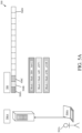
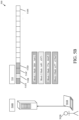
- FIGs. 5A-5D collectively is an illustration of an exemplary scenario of implementation of the data storage system and the data management device, in accordance with an embodiment of the present disclosure.
- FIGs. 5A-5D are described in conjunction with elements from FIGs. 1 , 2 , 3 , and 4 .
- FIGs. 5A-5D there is collectively shown an implementation scenario 500.
- a first user 502A there is shown a first user 502A, a first computing device 504A, and a first network attached server 506A (also represented as NAS 1).
- a first network attached server 506A also represented as NAS 1).
- a second user 502B a second computing device 504B, and a second network attached server 506B (also represented as NAS2).
- a storage representation 510 of the second network attached server 506B i.e., NAS2 that includes N number of blocks namely, a first block 510A, a second block 510B, a third block 510C, a fourth block 510D and up to a Nth block 510N.
- hash values associated with the first block 510A, the second block 510B, the third block 510C, the fourth block 510D and the fifth block 510E are "Block1 Hash: 2fd4... 3eb12", “Block2 Hash: 1e89...d5f73”, “Block3 Hash: 173e...866f5", “Block4 Hash: cc57...e33ba9", and “Block5 Hash: a54b...c41f8", respectively.
- both the files i.e., the movie file "CompanyEvent.mpeg” and the new movie file “CompanyEvent v2.mpeg" were stored on two different network attached servers, 506A and 506B and total number of blocks were 7.
- the data management device 202 may be configured to manage a matrix of communication (upload and download) between various NAS servers and decide for each list of similar files to which NAS to migrate them and to obtain the best communication.
- a matrix of communication upload and download
- one or more files from the list of similar files may stay in its current location and would not need to be replaced by the stub.
- the data management device 202 may locate the files where exist data transport acceleration like NVMe over Fabrics, also known as NVMe-oF or non-volatile memory express over fabrics.
- NVMe-oF may be defined as a protocol which is designed to provide data transfer between a host computer and a storage device or system over a network fabric.
Landscapes
- Engineering & Computer Science (AREA)
- Theoretical Computer Science (AREA)
- Physics & Mathematics (AREA)
- General Engineering & Computer Science (AREA)
- General Physics & Mathematics (AREA)
- Data Mining & Analysis (AREA)
- Databases & Information Systems (AREA)
- Human Computer Interaction (AREA)
- Information Retrieval, Db Structures And Fs Structures Therefor (AREA)
Description
- The present disclosure relates generally to the field of data management; and more specifically, to a method, a data management device and a data storage system for reducing primary and backup storage.
- Typically, data related to an entity, such as an enterprise or an organisation, is stored in terms of multiple data files and data objects which are further stored on various physical machines, virtual machines located on different hosts (e.g., VMware, Hyper-V, etc.) and data centres (e.g., network attached servers (NAS)). In case of storage of data in terms of the multiple data files and data objects, there may be duplicity of data files and similarity (i.e., partially same data) may also exist among the multiple data files, while saving the data related to the entire enterprise or the organisation.
- Currently, certain methods are available in order to reduce storage requirements, such as by use of compression, or by de-duplication of duplicate data files and similar (i.e., partially same) data files. Data de-duplication may be defined as a technique to eliminate duplicate copies of repeating data. Storage reduction methods can be applied to both a primary storage cluster and a secondary (backup) storage cluster. In case of use of the secondary storage cluster, depending on the scalability of the secondary storage cluster and size of the data centre, more than one secondary storage cluster may be needed in order to protect one data centre. In a back-up, different backup layouts may be used to store the backed-up data, such as incremental block level, file level, and data de-duplication. In all these layouts, data to be stored is either compressed and/or encrypted. In this way, the duplicate data files and the similar data files which may be stored on the same data centre, their backup layout is de-duplicated and hence, the de-duped data files may be stored in a backup repository with a partial efficiency. Alternatively stated, the backup layout with de-duplication reduces the backup storage capacity only for a specific data centre or partial of the specific data centre. However, there are limitations associated with the available methods, such as the duplicate data files and the similar data files which may be stored on different data centres are not de-duped efficiently in the backup storage because of the secondary storage protection scope. Therefore, the duplicate data files and the similar data files located on different data centres will continue to occupy more space and would not leverage de-duplication technique of primary storage or secondary storage. Thus, there exists a technical problem of inefficiently and inadequately handling the primary storage as well as the backup storage.
- Therefore, in light of the foregoing discussion, there exists a need to overcome the aforementioned drawbacks associated with the conventional methods of reducing the primary storage as well as the backup storage.
-
US 10 303 797 B1 -
US 2020/233752 A1 relates to a mostly unique file selection method for deduplication backup systems. - The present disclosure provides a method for reducing primary as well as backup storage. The present disclosure further provides a data management device and a data storage system for reducing primary and backup storage. The present disclosure provides a solution to the existing problem of inefficiently and inadequately handling and reducing the primary storage as well as the backup storage. An aim of the present disclosure is to provide a solution that overcomes at least partially the problems encountered in prior art, and provide an improved method, a data management device and a data storage system for reducing primary as well as backup storage. The object of the present disclosure is achieved by the solutions provided in the enclosed independent claims. Advantageous implementations of the present disclosure are further defined in the dependent claims.
- It has to be noted that all devices, elements, circuitry, units and means described in the present application could be implemented in the software or hardware elements or any kind of combination thereof. All steps which are performed by the various entities described in the present application as well as the functionalities described to be performed by the various entities are intended to mean that the respective entity is adapted to or configured to perform the respective steps and functionalities. Even if, in the following description of specific embodiments, a specific functionality or step to be performed by external entities is not reflected in the description of a specific detailed element of that entity which performs that specific step or functionality, it should be clear for a skilled person that these methods and functionalities can be implemented in respective software or hardware elements, or any kind of combination thereof. It will be appreciated that features of the present disclosure are susceptible to being combined in various combinations without departing from the scope of the present disclosure as defined by the appended claims.
- Additional aspects, advantages, features and objects of the present disclosure would be made apparent from the drawings and the detailed description of the illustrative implementations construed in conjunction with the appended claims that follow.
- The summary above, as well as the following detailed description of illustrative embodiments, is better understood when read in conjunction with the appended drawings. For the purpose of illustrating the present disclosure, exemplary constructions of the disclosure are shown in the drawings. However, the present disclosure is not limited to specific methods and instrumentalities disclosed herein. Moreover, those in the art will understand that the drawings are not to scale. Wherever possible, like elements have been indicated by identical numbers.
- Embodiments of the present disclosure will now be described, by way of example only, with reference to the following diagrams wherein:
- FIG. 1
- is a flowchart of a method of data management in a data storage system comprising a plurality of data storage units, in accordance with an embodiment of the present disclosure;
- FIG. 2
- is a block diagram that illustrates various exemplary components of a data management device, in accordance with an embodiment of the present disclosure;
- FIG. 3
- is a block diagram that illustrates various exemplary components of a data storage system, in accordance with an embodiment of the present disclosure;
- FIG. 4
- is a network environment diagram of communication between the data storage system and the data management device, in accordance with an embodiment of the present disclosure; and
- FIGs. 5A-5D
- collectively is an illustration of an exemplary scenario of implementation of the data storage system and the data management device, in accordance with an embodiment of the present disclosure.
- In the accompanying drawings, an underlined number is employed to represent an item over which the underlined number is positioned or an item to which the underlined number is adjacent. A non-underlined number relates to an item identified by a line linking the non-underlined number to the item. When a number is non-underlined and accompanied by an associated arrow, the non-underlined number is used to identify a general item at which the arrow is pointing.
- The following detailed description illustrates embodiments of the present disclosure and ways in which they can be implemented. Although some modes of carrying out the present disclosure have been disclosed, those skilled in the art would recognise that other embodiments for carrying out or practicing the present disclosure are also possible.
-
FIG. 1 is a flowchart of a method of data management in a data storage system comprising a plurality of data storage units, in accordance with an embodiment of the present disclosure. With reference toFIG. 1 , there is shown amethod 100 of data management in a data storage system comprising a plurality of data storage units. Themethod 100 includes steps 102-to-110. Themethod 100 is executed by a data management device and a data storage system, described in detail, for example, inFIGs. 2 and 3 , respectively. - The present disclosure provides a computer-implemented method (i.e., the method 100) of data management in a data storage system comprising a plurality of data storage units, the
method 100 comprising: - dividing each file in the data storage system into a plurality of blocks having a common size;
- generating a hash value for each block using a common hash algorithm;
- identifying a plurality of similar files in different data storage units, based on a comparison of the hashes for each file;
- copying one or more of the identified similar files, such that similar files are stored in a single data storage unit; and
- for one or more of the copied files, generating a link to a new location of the file.
- The
method 100 improves an unstructured data management of an entire enterprise storage system. Themethod 100 includes collecting information of an unstructured data that may be stored on different sources of the entire enterprise storage, such as a data centre (e.g., network attached server (NAS)), a data object (e.g., Amazon S3), a virtual machine (VM), or a physical machine, etc. The information may be collected either periodically or as a "live update". The collected information may be a native meta data with an additional synthetic data, for example, input or output temperature of a file. - At
step 102, themethod 100 comprises dividing each file in the data storage system into a plurality of blocks having a common size. For example, video file or an audio file is divided into the plurality of blocks while saving the video file or the audio file in the data storage system (e.g., a data centre, or a NAS). Each of the plurality of blocks is of the common size but has different data. The data storage system may have one or more data storage units (or devices), such as physical machines, virtual machines, data centres (or network attached servers), and the like. The data storage system represents a storage system of the entire enterprise storage or an organisation. - At
step 104, themethod 100 further comprises generating a hash value for each block using a common hash algorithm. The hash value for each block of the plurality of blocks is generated by use of the common hash algorithm. For example, a secure hash algorithm 1 (SHA-1) may be used to generate the hash for each block of the plurality of blocks. Generally, the secure hash algorithm 1 (SHA-1) may be defined as a cryptographic hash function which takes an input and generates a hash value of 160 bits in output. - At
step 106, themethod 100 further comprises identifying a plurality of similar files in different data storage units, based on a comparison of the hashes for each file. In an example, multiple video files or audio files may be stored on different data centres (or network attached servers), or physical machines or virtual machines. In such a case, the hash (or the hash value) associated with each block of the plurality of blocks of each video file or the audio file is compared with each other. After comparison, the plurality of similar files (i.e., the files having each block of the plurality of blocks having same hashes or hash values) is identified. For example, the multiple video files or audio files may be identified as the plurality of similar files if 5 highest weak hashes stored per file are found as same. - At
step 108, themethod 100 further comprises copying one or more of the identified similar files, such that similar files are stored in a single data storage unit. The one or more of the identified similar files are copied in the single data storage unit (e.g., a centralised network attached server) in order to ease the de-duplication of the one or more of the identified similar files resulting into reduction of primary storage. This further results into an improved detection time of duplicate and similar files stored across the entire enterprise storage. - At
step 110, themethod 100 further comprises for one or more of the copied files, generating a link to a new location of the file. The one or more of the identified similar files which are stored (or copied) in the single data storage unit are termed as the one or more copied files. For each of the one or more copied files, the link to the new location (i.e., the centralised network attached server) is provided as a stub in the source file, hence, results into reduction of primary storage as well as secondary storage. - In accordance with an embodiment, identifying the plurality of similar files includes collecting one or more hash values from each file in the data storage system and comparing the collected hash values. The plurality of similar files is identified by collecting one or more hash values (or the hashes) associated with the plurality of blocks of each file stored in the data storage system. The collected one or more hash values (or the hashes) associated with the plurality of blocks of each file that is stored in the data storage system, are compared with each other.
- In accordance with an embodiment, the
method 100 further comprises collecting a predefined number of hash values from each file, wherein the collected hash values are the highest for each file. For comparison of the one or more hash values (or the hashes) associated with the plurality of blocks of each file, the predefined number of hash values from each file are collected. The collected hash values are the highest hash values stored per file. For example, the plurality of similar files may be identified if 5 highest weak hashes (e.g., weak hash - 8bytes) stored per file are collected from one or more data storage systems and found as same on comparison with each other. The 5 highest weak hashes stored per file may be collected in various ways, for example, by use of primary storage, such as an application programming interface (API). - Collecting hash values from each file in the data storage system includes filtering the hash values according to a minimum file size, or file type. The collection of the hash values of the plurality of blocks of each file in the data storage system depends on filtering the hash values based on the minimum file size or the file type, such as .jpg file, or .mpeg file, etc.
- In accordance with an embodiment, identifying the plurality of similar files includes determining a percentage number of blocks in common and comparing the determined percentage to a minimum threshold value. The plurality of similar files is identified on the basis of the percentage number of blocks which are common in one or more files. Moreover, the percentage number of blocks common in one or more files are compared to the minimum threshold value. For example, a video file stored in the data storage system is divided into 3 blocks. Another video file stored in the data storage system is divided into 4 blocks. The first two blocks of the video file and the other video file are common in both the files. Therefore, the percentage number of blocks in common among the video file and the other video file may be approximately 57 percent. The percentage number of blocks in common (i.e., the 57%) is further compared with the minimum threshold value.
- In accordance with an embodiment, copying the identified similar files comprises copying both files to a centralised data storage unit. The identified similar files are copied to the centralised data storage unit (e.g., a centralised network attached server) so that the identified similar files are de-duped by the centralised data storage unit with more ease resulting into reduction of primary storage as well as secondary storage. The storage (or backup) of similar files that were stored on different data storage units (or secondary storage cluster) can now be stored on the same data storage unit (or cluster) and by leveraging data de-duplication technique, the backup storage space (or the secondary storage space) may be reduced significantly.
- In accordance with an embodiment, copying the similar files comprises selecting the data storage unit of one file as an optimal storage location, and copying one or more other similar files to the optimal storage location. For example, in case of two identified similar files, the data storage unit of a bigger file among the two identified similar files is considered as the optimal storage location and a smaller file among the two identified similar files is copied to the optimal storage location.
- In accordance with an embodiment, the optimal storage location is selected to minimise the volume of data to be copied. The optimal storage location is selected in order to ease the data de-duplication of the volume of data to be copied to the optimal storage location. For example, the centralised network attached server is selected as the optimal storage location in order to minimise the volume of data to be copied by use of the data de-duplication.
- In accordance with an embodiment, the optimal storage location is selected based on an access speed or reliability of the data storage units. For example, in case of a sensitive or an important data, the selection of the optimal storage location is performed on the basis of the access speed or reliability of the data storage units. In case of the sensitive data, the identified similar files are copied to multiple data storage units rather than one data storage unit. In such a case, the access speed and reliability of the multiple data storage units is of primary concern due to protection level of the sensitive data.
- In accordance with an embodiment, the data storage system is a network-based system. The data storage system is the network-based system, such as the centralised network attached server (NAS), or a cloud network which is linked with a network, for example, an internet.
- Thus, the
method 100 efficiently reduces the primary storage as well as the secondary storage space. The storage (or backup) of duplicate files and similar (i.e., partially the same) files that were stored on different data storage units (or secondary storage cluster) can now be stored on the same data storage unit (or cluster) and by leveraging data de-duplication technique, the backup storage space (or the secondary storage space) may be reduced significantly. Moreover, themethod 100 improves detection time of duplicate files and similar (i.e., partially the same) files across the entire enterprise storage. - The
steps 102 to 110 are only illustrative and other alternatives can also be provided where one or more steps are added, one or more steps are removed, or one or more steps are provided in a different sequence without departing from the scope of the claims herein. -
FIG. 2 is a block diagram that illustrates various exemplary components of a data management device, in accordance with an embodiment of the present disclosure.FIG. 2 is described in conjunction with elements fromFIG. 1 . With reference toFIG. 2 , there is shown a block diagram 200 of adata management device 202 for a data storage system that includes a plurality ofdata storage units 204, amemory 206 and aprocessor 208. The plurality ofdata storage units 204 and thememory 206 may be communicatively coupled to theprocessor 208. Theprocessor 208 of thedata management device 202 executes the method 100 (ofFIG. 1 ). The data storage system is described in detail, for example, inFIG. 3 . - The
data management device 202 includes suitable logic, circuitry, interfaces, or code that is configured to collect information of an unstructured data that may be stored on different data storage units of the entire enterprise storage, such as a data centre (e.g., network attached server (NAS)), a data object (e.g., Amazon S3), a virtual machine (VM), or a physical machine, etc. The information may be collected either periodically or as a "live update" by use of the plurality of data storage units 204 (e.g., collector). The plurality of data storage units 204 (e.g., collector) may run in-host or outside of the host. The collected information may be a native meta data with an additional synthetic data, for example, input or output temperature of a file may be obtained by calculating number of reads per file in the last 24 hours or any other synthetic information. Thedata management device 202 may be configured to run different type of queries and perform an analysis and supply insights on a customer storage enterprise. For example, thedata management device 202 may be configured to find hot and cold data according to a customer policy. Examples of thedata management device 202 include, but are not limited to an artificial intelligence (AI) catalog engine, a mainframe computer, and the like. In an example, thedata management device 202 may be a single computing device or an electronic device. In another example, thedata management device 202 may be a plurality of computing devices, or electronic devices, operating in a parallel or distributed architecture. In a yet another example, thedata management device 202 may be implemented as a computer program that provides various services (such as database management) to other devices, modules or apparatus. - The plurality of
data storage units 204 includes suitable logic, circuitry, interfaces, or code that is configured to store data. Examples of the plurality ofdata storage units 204 include, but are not limited to a primary storage (e.g., the memory 206), a secondary storage, such as a memory of a virtual machine, a network attached server (NAS), a collector, and the like. The virtual machine may be located on different hosts or hosts type, such as VMware, Hyper-V, etc. - The
memory 206 includes suitable logic, circuitry, interfaces, or code that is configured to store data and the instructions executable by theprocessor 208. Examples of implementation of thememory 206 may include, but are not limited to, an Electrically Erasable Programmable Read-Only Memory (EEPROM), Random Access Memory (RAM), Read Only Memory (ROM), Hard Disk Drive (HDD), Flash memory, Solid-State Drive (SSD), or CPU cache memory. Thememory 206 may store an operating system or other program products (including one or more operation algorithms) to operate thedata management device 202. - The
processor 208 includes suitable logic, circuitry, interfaces, or code that is configured to execute the instructions stored in thememory 206. In an example, theprocessor 208 may be a general-purpose processor. Other examples of theprocessor 208 may include, but is not limited to a microprocessor, a micro-controller, a complex instruction set computing (CISC) processor, an application-specific integrated circuit (ASIC) processor, a reduced instruction set (RISC) processor, a very long instruction word (VLIW) processor, a central processing unit (CPU), a state machine, a data processing unit, and other processors or control circuitry. Moreover, theprocessor 208 may refer to one or more individual processors, processing devices, a processing unit that is part of a machine, such as thedata management device 202. - In operation, the
data management device 202 is configured to divide each file in the data storage system into a plurality of blocks having a common size. For example, the data management device 202 (e.g., AI catalog engine) divides a data file (e.g., video file, audio file, .jpg file, .mpeg file, etc.) into the plurality of blocks while saving the data file into the data storage system. Each of the plurality of blocks is of the common size but has different data. - The
data management device 202 is further configured to generate a hash value for each block using a common hash algorithm. The hash value for each block of the plurality of blocks of the data file may be generated by use of the common hash algorithm, for example, a secure hash algorithm 1 (SHA-1). - The
data management device 202 is further configured to identify a plurality of similar files in different data storages, based on a comparison of the hashes for each file. In a case, multiple data files may be stored on the plurality of data storage units 204 (e.g., collectors) of thedata management device 202. The plurality ofdata storage units 204 may be configured to provide information of the unstructured data to thedata management device 202, such as a file system (e.g., NAS) native metadata, synthetic metadata properties such as statistics (e.g., average changes per day), collector ID, unique NAS information, etc. The plurality ofdata storage units 204 may be configured to obtain de-duplication information. For example, the plurality ofdata storage units 204 may be configured to obtain for each file 5 highest weak hashes and that may be performed in various ways, such as by use of a primary storage API. Additionally, the plurality ofdata storage units 204 may be configured to provide the information about the hash algorithm and block size to thedata management device 202 in order to process each file and store each file into a backend (i.e., persistent storage, e.g., elastic search). After receiving the information form the plurality ofdata storage units 204, thedata management device 202 is configured to run periodic queries in order to find the plurality of similar files. In such a case,data management device 202 is configured to compare the hash (or the hash value) associated with each block of the plurality of blocks of each data file stored on the plurality ofdata storage units 204. After comparison,data management device 202 identifies the plurality of similar files by finding a similarity greater than equal to a certain threshold value (i.e., x%). The threshold value is obtained by finding same hashes for each block of the plurality of blocks of each file. - The
data management device 202 is further configured to copy one or more of the identified similar files, such that similar files are stored in a single data storage. After identification of the plurality of similar files, thedata management device 202 is configured to copy the one or more identified similar files in the single data storage (e.g., a centralised network attached server) in order to ease de-duplication of the one or more of the identified similar files resulting into reduction of primary storage of thedata management device 202. - The
data management device 202 is further configured to for one or more of the copied files, generate a link to a new location of file. After copying the one or more identified similar files, thedata management device 202 is further configured to generate the link of the new location for each of the one or more copied files in a source file. This further results into reduction of primary storage as well as secondary storage of thedata management device 202. - In accordance with an embodiment, identifying the plurality of similar files includes collecting one or more hash values from each file in the data storage system and comparing the collected hash values. The
data management device 202 is configured to identify the plurality of similar files by collecting and then, comparing one or more hash values (or the hashes) associated with each of the plurality of blocks of each file stored in the data storage system. - In accordance with an embodiment, the
data management device 202 is further configured to collect a predefined number of hash values from each file, wherein the collected hash values are the highest for each file. For example, the plurality of similar files may be identified if 5 highest weak hashes (e.g., weak hash - 8bytes) stored per file are collected from the data storage system and found as same on comparison with each other. - In accordance with an embodiment, collecting hash values from each file in the data storage system includes filtering the hash values according to a minimum file size, or file type. The
data management device 202 is further configured to filter the hash values collected from each file on the basis of the minimum file size of the file type, such as.jpg file, or .mpeg file, etc. - In accordance with an embodiment, identifying the plurality of similar files includes determining a percentage number of blocks in common and comparing the determined percentage to a minimum threshold value. The
data management device 202 is configured to identify the plurality of similar files on the basis of the percentage number of blocks which are common in one or more files. Moreover, the percentage number of blocks common in one or more files are compared to the minimum threshold value. - In accordance with an embodiment, copying the identified similar files comprises copying both files to a centralised data storage. The
data management device 202 is configured to copy the identified similar files to the centralised data storage (e.g., a centralised and configurable network attached server) so that the identified similar files are de-duped with more ease resulting into reduction of primary storage as well as secondary storage (i.e., the memory 206) of thedata management device 202. - In accordance with an embodiment, copying the similar files comprises selecting the data storage of one file as an optimal storage location, and copying one or more other similar files to the optimal storage location. The
data management device 202 is configured to select the optimal storage location. In an example, thedata management device 202 may decide for the similar files to which network attached server (NAS) to copy them in order to obtain maximum benefit from de-duplication and replace with the link of the new location for each of the one or more copied files in a source file. - In accordance with an embodiment, the optimal storage location is selected to minimise the volume of data to be copied. The
data management device 202 is configured to select the optimal storage location in order to ease the de-duplication of the one or more copied files resulting into reduction of volume of data to be copied. - In accordance with an embodiment, the optimal storage location is selected based on an access speed or reliability of the data storage. For example, in case of a sensitive data, the
data management device 202 is configured to select the optimal storage location on the basis of protection level of the sensitive data. In such a case, thedata management device 202 is configured to copy the identified similar files to multiple data storage units rather than one data storage unit. In such a case, the access speed and reliability of the multiple data storage units is of primary concern due to protection level of the sensitive data. - In accordance with an embodiment, the data storage system is a network-based system. The data storage system is the network-based system, such as the centralised network attached server (NAS), or a cloud network which is linked with a network, for example, an internet.
- In accordance with an embodiment, a computer-readable medium configured to store instruction which, when executed by the
processor 208, cause theprocessor 208 to perform the method 100 (ofFIG. 1 ). Theprocessor 208 of thedata management device 202 is configured to execute the method 100 (ofFIG. 1 ). - Thus, the data management device 202 (i.e., the AI catalog engine) efficiently manages the unstructured data that is stored on the entire enterprise storage by collecting the information of the unstructured data using the plurality of
data storage units 204. The data management device 202 (i.e., the AI catalog engine) provides the information of the plurality of similar files and copy them to the centralised and configurable data storage system and replace each of the plurality of similar files with the corresponding stub (i.e., the link of the new location) in the source file system. This results into an improved de-duplication of the plurality of similar files copied on the centralised data storage system and hence, into reduction of primary storage and secondary storage of thedata management device 202. Additionally, thedata management device 202 improves detection time of the plurality of similar files across the entire enterprise storage. -
FIG. 3 is a block diagram that illustrates various exemplary components of a data storage system, in accordance with an embodiment of the present disclosure.FIG. 3 is described in conjunction with elements fromFIGs. 1 , and2 . With reference toFIG. 3 , there is shown a block diagram 300 of adata storage system 302 that includes one or more interconnecteddata storage units 304, amemory 306 and aprocessor 308. The one or more interconnecteddata storage units 304, and thememory 306 may be communicatively coupled to theprocessor 308. Theprocessor 308 of thedata storage system 302 executes the method 100 (ofFIG. 1 ). - The
data storage system 302 includes suitable logic, circuitry, interfaces, or code that is configured to store data. Thedata storage system 302 may have one or more data storage units (or devices), such as physical machines, virtual machines, data centres (or network attached servers), collectors, and the like. Thedata storage system 302 represents a storage system of the entire enterprise storage or a subset of the entire enterprise or an organisation. Examples of thedata storage system 302 may include, but are not limited to a data centre, network attached server, and the like. - The one or more interconnected
data storage units 304 corresponds to the plurality ofdata storage units 204 of the data management device 202 (ofFIG. 2 ). - The
memory 306 includes suitable logic, circuitry, interfaces, or code that is configured to store data and the instructions executable by theprocessor 308. Examples of implementation of thememory 306 may include, but are not limited to, an Electrically Erasable Programmable Read-Only Memory (EEPROM), Random Access Memory (RAM), Read Only Memory (ROM), Hard Disk Drive (HDD), Flash memory, Solid-State Drive (SSD), or CPU cache memory. Thememory 306 may store an operating system or other program products (including one or more operation algorithms) to operate thedata storage system 302. - The
processor 308 includes suitable logic, circuitry, interfaces, or code that is configured to execute the instructions stored in thememory 306. In an example, theprocessor 308 may be a general-purpose processor. Other examples of theprocessor 308 may include, but is not limited to a microprocessor, a micro-controller, a complex instruction set computing (CISC) processor, an application-specific integrated circuit (ASIC) processor, a reduced instruction set (RISC) processor, a very long instruction word (VLIW) processor, a central processing unit (CPU), a state machine, a data processing unit, and other processors or control circuitry. Moreover, theprocessor 308 may refer to one or more individual processors, processing devices, a processing unit that is part of a machine, such as thedata storage system 302. -
FIG. 4 is a network environment diagram of communication between the data storage system and the data management device, in accordance with an embodiment of the present disclosure.FIG. 4 is described in conjunction with elements fromFIGs. 1 ,2, and 3 . With reference toFIG. 4 , there is shown anetwork environment 400 that includes a plurality of data storage systems, such as a firstdata storage system 402A up to a Nthdata storage system 402N. The firstdata storage system 402A includes one or more interconnected data storage units, such as a firstdata storage unit 404A, and a seconddata storage unit 404B. Similarly, the Nthdata storage system 402N includes one or more interconnected data storage units, such as a firstdata storage unit 406A, a seconddata storage unit 406B, a thirddata storage unit 406C and a fourthdata storage unit 406D. Thenetwork environment 400 further includes thedata management device 202 and anelastic search 408. Thedata management device 202 further includes aninternal collector 202A. Each of the firstdata storage unit 404A, and the seconddata storage unit 404B of the firstdata storage system 402A includes acollector 410. Similarly, the firstdata storage unit 406A of the Nthdata storage system 402N includes thecollector 410. - In the
network environment 400, thedata management device 202 is configured to receive the data from the plurality of data storage systems, such as the firstdata storage system 402A up to the Nthdata storage system 402N. In an example, the firstdata storage system 402A and the Nthdata storage system 402N may also be represented as adata centre 1 and a data centre N, respectively. The firstdata storage unit 404A and the seconddata storage unit 404B of the firstdata storage system 402A may be represented as a network attached server 1 (NAS1) and a data object (e.g., S3). Similarly, the firstdata storage unit 406A, the seconddata storage unit 406B, the thirddata storage unit 406C and the fourthdata storage unit 406D of the Nthdata storage system 402N may be represented as a network attached server 7 (NAS7), production ESX server, production MSSQL and production oracle, respectively. - The
collector 410 associated with the firstdata storage units data storage unit 404B may be defined as an agent that run inside or outside the firstdata storage units data storage unit 404B, respectively and collect metadata of various data files. In an implementation, thecollector 410 may also be referred to as a software implemented on the firstdata storage units data storage unit 404B, and configured to access data files, data objects and the like, and perform various functions associated with the data backup. Thecollector 410 may be configured to detect one or more operations executing one or more changes in the data files. - The data management device 202 (i.e., AI catalog engine) is configured to manage the data (i.e., unstructured data) that is stored on the plurality of data storage systems, such as the first
data storage system 402A up to the Nthdata storage system 402N. Moreover, theinternal collector 202A associated with the data management device 202 (i.e., AI catalog engine) may be configured to collect the data from each of the seconddata storage unit 406B (i.e., the production ESX server), the thirddata storage unit 406C (i.e., the production MSSQL) and the fourthdata storage unit 406D (i.e., the production oracle) of the Nthdata storage system 402N. The data management device 202 (i.e., AI catalog engine) may also be configured to move data (i.e., data files or data objects) between different tiers (e.g., from NAS1 to NAS7) or internally (e.g., from NAS1 to S3). The data management device 202 (i.e., AI catalog engine) is configured to provide the information on a plurality of similar files and copy them to the centralised and configurable data storage system and replace each of the plurality of similar files with the corresponding stub (i.e., the link of the new location) in the source file system. This results into an improved de-duplication of the plurality of similar files copied on the centralised data storage system and hence, into reduction of primary storage and secondary storage of thedata management device 202. Additionally, thedata management device 202 improves detection time of the plurality of similar files across the plurality of data storage systems, such as the firstdata storage system 402A up to the Nthdata storage system 402N. Moreover, the data management device 202 (i.e., AI catalog engine) may also be configured to store each processed data file into theelastic search 408 which acts as a backup repository or a persistent storage. -
FIGs. 5A-5D collectively is an illustration of an exemplary scenario of implementation of the data storage system and the data management device, in accordance with an embodiment of the present disclosure.FIGs. 5A-5D are described in conjunction with elements fromFIGs. 1 ,2 ,3 , and4 . With reference toFIGs. 5A-5D , there is collectively shown animplementation scenario 500. With reference toFIG. 5A , there is shown afirst user 502A, afirst computing device 504A, and a first network attachedserver 506A (also represented as NAS 1). There is further shown astorage representation 508 of the first network attachedserver 506A (i.e., NAS1) that includes N number of blocks namely, afirst block 508A, asecond block 508B, athird block 508C and up to aNth block 508N. - With reference to
FIG. 5B , there is shown asecond user 502B, asecond computing device 504B, and a second network attachedserver 506B (also represented as NAS2). There is further shown astorage representation 510 of the second network attachedserver 506B (i.e., NAS2) that includes N number of blocks namely, afirst block 510A, asecond block 510B, athird block 510C, afourth block 510D and up to aNth block 510N. - With reference to the
implementation scenario 500, thefirst user 502A and thesecond user 502B work together in an organisation (e.g., in a company "x") and has its own NAS share to upload their corresponding data files. - Referring back to
FIG. 5A , thefirst user 502A receives a movie file of the company's event on thefirst computing device 504A. The movie file is named as "CompanyEvent.mpeg". Thefirst user 502A copies the movie file from thefirst computing device 504A to the first network attachedserver 506A (i.e., NAS1). The link of the movie file "CompanyEvent.mpeg" on the first network attachedserver 506A (i.e., NAS1) is "\\nas1_IP\user1\MyVideos\CompanyEvent.mpeg". The movie file "CompanyEvent.mpeg" is stored on three blocks of the first network attachedserver 506A (i.e., NAS1), such as thefirst block 508A, thesecond block 508B and thethird block 508C. Each of thefirst block 508A, thesecond block 508B and thethird block 508C has different data and different hash value. For example, the hash value associated with thefirst block 508A, thesecond block 508B and thethird block 508C is "Block1 Hash: 2fd4...3eb12", "Block2 Hash: 1e89...d5f73", and "Block3 Hash: a54b...c41f8", respectively. - Now referring to
FIG. 5B , thesecond user 502B receives the same movie file (i.e., "CompanyEvent.mpeg") of the company's event on thesecond computing device 504B. Thesecond user 502B may be configured to perform some editing to the movie file and concatenate an additional short movie from the company event and created a new movie file which is named as "CompanyEvent v2.mpeg". Thesecond user 502B copies the new movie file from thesecond computing device 504B to the second network attachedserver 506B (i.e., NAS2). The link of the new movie file "CompanyEvent_v2.mpeg" on the second network attachedserver 506B (i.e., NAS2) is "\\nas2_IP\user2\MyDocs\videos\CompanyEvent_v2.mpeg". The new movie file "CompanyEvent_v2.mpeg" is stored on four blocks of the second network attachedserver 506B (i.e., NAS2), such as thefirst block 510A, thesecond block 510B, thethird block 510C, and thefourth block 510D. Each of thefirst block 510A, thesecond block 510B, thethird block 510C and thefourth block 510D has different data and different hash value. For example, hash values associated with thefirst block 510A, thesecond block 510B, thethird block 510C, and thefourth block 510D are "Block1 Hash: 2fd4...3eb12", "Block2 Hash: 1e89...d5f73", "Block3 Hash: 173e... 866f5", and "Block4 Hash: cc57...e33ba9", respectively. - The movie file "CompanyEvent.mpeg" and the new movie file "CompanyEvent v2.mpeg" are approximately similar. The reason is each of the
first blocks second blocks third blocks fourth block 510D exists only for the new movie file "CompanyEvent_v2.mpeg". In such a case, the data management device 202 (i.e., AI catalog engine) is configured to identify a plurality of similar files that is the movie file "CompanyEvent.mpeg" and the new movie file "CompanyEvent _v2.mpeg". The data management device 202 (i.e., AI catalog engine) is further configured to copy the movie file "CompanyEvent.mpeg" of thefirst user 502A to the second network attachedserver 506B (i.e., NAS2) whose link is "\\nas2_IP\similarFiles\fromUser1\MyVideos\CompanyEvent.mpeg" and replace the source on the first network attachedserver 506A (i.e., NAS1) with a stub (i.e., a link to the new location in the second network attachedserver 506B), as shown inFIG. 5C . - Now, referring to
FIG. 5C , at the first network attachedserver 506A (i.e., NAS1), the link of the movie file "CompanyEvent.mpeg" of thefirst user 502A is changed from "\\nas1_IP\user1\MyVideos\CompanyEvent.mpeg" to "\\nas2_IP\similarFiles\fromUser1\MyVideos\CompanyEvent.mpeg" as the movie file "CompanyEvent.mpeg" is replaced with the stub (i.e., the link to the new location in the second network attachedserver 506B). - After copying the movie file "CompanyEvent.mpeg" of the
first user 502A to the second network attachedserver 506B (i.e., NAS2) of thesecond user 502B, both files (i.e., the movie file "CompanyEvent.mpeg" and the new movie file "CompanyEvent v2.mpeg") are located at the same location (or same storage pool) so that the both files are easily de-duped, described in detail, for example, inFIG. 5D . - Referring to
FIG. 5D , after de-duplication, both the files (i.e., the movie file "CompanyEvent.mpeg" and the new movie file "CompanyEvent v2.mpeg") are stored on five blocks of the second network attachedserver 506B (i.e., NAS2). The five blocks are thefirst block 510A, thesecond block 510B, thethird block 510C, thefourth block 510D and thefifth block 510E. Each of thefirst block 510A, thesecond block 510B, thethird block 510C, thefourth block 510D and thefifth block 510E has different data and different hash values. For example, hash values associated with thefirst block 510A, thesecond block 510B, thethird block 510C, thefourth block 510D and thefifth block 510E are "Block1 Hash: 2fd4... 3eb12", "Block2 Hash: 1e89...d5f73", "Block3 Hash: 173e...866f5", "Block4 Hash: cc57...e33ba9", and "Block5 Hash: a54b...c41f8", respectively. Before, de-duplication, both the files (i.e., the movie file "CompanyEvent.mpeg" and the new movie file "CompanyEvent v2.mpeg") were stored on two different network attached servers, 506A and 506B and total number of blocks were 7. - In a case, if the movie file "CompanyEvent.mpeg" and the new movie file "CompanyEvent v2.mpeg" are identical, then, in such a case, the
data management device 202 would not copy the file. In another case, if the movie file "CompanyEvent.mpeg" and the new movie file "CompanyEvent v2.mpeg" are not identical, then, in such a case, thedata management device 202 is configured to copy a smaller file (i.e., the "CompanyEvent.mpeg") from the first network attachedserver 506A (i.e., NAS1) to a bigger file (i.e., the "CompanyEvent_v2.mpeg") stored on the second network attachedserver 506B (i.e., NAS2). In a yet another case, thedata management device 202 may be configured to copy both of the files to a centralised network attached server (e.g., a 3rd NAS) depending on an application scenario. - Optionally, the
data management device 202 may be configured to manage a matrix of communication (upload and download) between various NAS servers and decide for each list of similar files to which NAS to migrate them and to obtain the best communication. In the matrix of communication, one or more files from the list of similar files may stay in its current location and would not need to be replaced by the stub. Using the matrix of communication, thedata management device 202 may locate the files where exist data transport acceleration like NVMe over Fabrics, also known as NVMe-oF or non-volatile memory express over fabrics. NVMe-oF may be defined as a protocol which is designed to provide data transfer between a host computer and a storage device or system over a network fabric. - In this
implementation scenario 500, thefirst user 502A and thesecond user 502B and the two similar files are considered, however, there may be a plurality of users using a plurality of NAS servers and a plurality of similar files. By using thedata management device 202, the storage space (i.e., the storage space related to an enterprise or a subset of the enterprise or an organisation) can be efficiently used. - Modifications to embodiments of the present disclosure described in the foregoing are possible without departing from the scope of the present disclosure as defined by the accompanying claims. Expressions such as "including", "comprising", "incorporating", "have", "is" used to describe and claim the present disclosure are intended to be construed in a non-exclusive manner, namely allowing for items, components or elements not explicitly described also to be present. Reference to the singular is also to be construed to relate to the plural. The word "exemplary" is used herein to mean "serving as an example, instance or illustration". Any embodiment described as "exemplary" is not necessarily to be construed as preferred or advantageous over other embodiments and/or to exclude the incorporation of features from other embodiments. The word "optionally" is used herein to mean "is provided in some embodiments and not provided in other embodiments". It is appreciated that certain features of the present disclosure, which are, for clarity, described in the context of separate embodiments, may also be provided in combination in a single embodiment. Conversely, various features of the present disclosure, which are, for brevity, described in the context of a single embodiment, may also be provided separately or in any suitable combination or as suitable in any other described embodiment of the disclosure.
Claims (18)
- A computer-implemented method (100) of data management in a data storage system (302) comprising a plurality of data storage units (204), the method (100) comprising:dividing each file in the data storage system (302) into a plurality of blocks having a common size;generating a hash value for each block using a common hash algorithm;identifying a plurality of similar files in different data storage units (204), based on a comparison of the hashes for each file;moving one or more of the identified similar files, such that similar files are stored in a single data storage unit; andfor each of said one or more of the moved files, generating a link to the new location of the file; andde-duplicating the files in said single data storage unit based on the hash values,characterized in thatidentifying the plurality of similar files includes collecting a predefined number of hash values from each file having a minimum file size, wherein the collected hash values are the highest of each file.
- The method (100) of claim 1, wherein collecting hash values from each file in the data storage system (302) includes filtering the hash values according to a minimum file size, or file type.
- The method (100) of any preceding claim, wherein identifying the plurality of similar files includes determining a percentage number of blocks in common and comparing the determined percentage to a minimum threshold value.
- The method (100) of any preceding claim, wherein moving the identified similar files comprises moving them to a centralised data storage unit.
- The method (100) of any one of claims 1 to 3, wherein moving the similar files comprises selecting the data storage unit of one file as an optimal storage location, and moving one or more other similar files to the optimal storage location.
- The method (100) of claim 5, wherein the optimal storage location is selected to minimise the volume of data to be moved.
- The method (100) of claim 5, wherein the optimal storage location is selected based on an access speed or reliability of the data storage units (204).
- The method (100) of any preceding claim, wherein the data storage system (302) is a network-based system.
- A computer-readable medium configured to store instruction which, when executed by a processor (208, 308), cause the processor (208, 308) to perform the method (100) of any preceding claim.
- A data management device (202) for a data storage system (302) comprising a plurality of data storage units (204), the data management device (202) configured to:divide each file in the data storage system (302) into a plurality of blocks having a common size;generate a hash value for each block using a common hash algorithm;identify a plurality of similar files in different data storage units, based on a comparison of the hashes for each file;move one or more of the identified similar files, such that similar files are stored in a single data storage unit; andfor each of said one or more of the moved files, generate a link to the new location of the file; andde-duplicate the files in said single data storage unit based on the hash values,characterized in thatidentifying the plurality of similar files includes collecting a predefined number of hash values from each file having a minimum file size, wherein the collected hash values are the highest for each file.
- The device (202) of claim 10, wherein collecting hash values from each file in the data storage system (302) includes filtering the hash values according to a minimum file size, or file type.
- The device (202) of any one of claims 10 or 11, wherein identifying the plurality of similar files includes determining a percentage number of blocks in common and comparing the determined percentage to a minimum threshold value.
- The device (202) of any one of claims 10 to 12, wherein moving the identified similar files comprises moving them to a centralised data storage unit.
- The device (202) of any one of claims 10 to 12, wherein moving the similar files comprises selecting the data storage unit of one file as an optimal storage location, and moving one or more other similar files to the optimal storage location.
- The device (202) of claim 14, wherein the optimal storage location is selected to minimise the volume of data to be moved.
- The device (202) of claim 14, wherein the optimal storage location is selected based on an access speed or reliability of the data storage unit.
- The device (202) of any preceding claim, wherein the data storage system (302) is a network-based system.
- A data storage system (302) comprising:one or more interconnected data storage units (304); andthe data management device (202) of any one of claims 10 to 17.
Applications Claiming Priority (1)
| Application Number | Priority Date | Filing Date | Title |
|---|---|---|---|
| PCT/EP2021/061610 WO2022233393A1 (en) | 2021-05-04 | 2021-05-04 | Method for reducing primary and backup storage |
Publications (2)
| Publication Number | Publication Date |
|---|---|
| EP4208774A1 EP4208774A1 (en) | 2023-07-12 |
| EP4208774B1 true EP4208774B1 (en) | 2025-07-09 |
Family
ID=75825810
Family Applications (1)
| Application Number | Title | Priority Date | Filing Date |
|---|---|---|---|
| EP21723869.0A Active EP4208774B1 (en) | 2021-05-04 | 2021-05-04 | Method for reducing primary and backup storage |
Country Status (4)
| Country | Link |
|---|---|
| US (1) | US12360947B2 (en) |
| EP (1) | EP4208774B1 (en) |
| CN (1) | CN117015758A (en) |
| WO (1) | WO2022233393A1 (en) |
Family Cites Families (43)
| Publication number | Priority date | Publication date | Assignee | Title |
|---|---|---|---|---|
| US6601236B1 (en) * | 1999-03-29 | 2003-07-29 | International Business Machines Corporation | Cross platform program installation on drives using drive object |
| US7769643B2 (en) * | 2001-02-08 | 2010-08-03 | The Boeing Company | Min/max inventory control system and associated method and computer program product |
| AU2002303126A1 (en) * | 2001-03-16 | 2002-10-03 | Novell, Inc. | Client-server model for synchronization of files |
| US7363278B2 (en) * | 2001-04-05 | 2008-04-22 | Audible Magic Corporation | Copyright detection and protection system and method |
| US8041803B2 (en) * | 2001-09-26 | 2011-10-18 | Qurio Holdings, Inc. | Method and system for delivering files in digital file marketplace |
| US7814078B1 (en) * | 2005-06-20 | 2010-10-12 | Hewlett-Packard Development Company, L.P. | Identification of files with similar content |
| US20070139231A1 (en) * | 2005-10-19 | 2007-06-21 | Advanced Digital Forensic Solutions, Inc. | Systems and methods for enterprise-wide data identification, sharing and management in a commercial context |
| US7797332B1 (en) * | 2006-01-17 | 2010-09-14 | Fortinet, Inc. | Computer-implemented method and device for providing security on a computer network |
| US9002744B2 (en) * | 2006-07-28 | 2015-04-07 | Sony Corporation | Methods, systems and computer program products for determining usage rights for digital content based on characterizing information thereof and related devices |
| CN101110759A (en) * | 2006-07-20 | 2008-01-23 | 朗迅科技公司 | Peer-to-Peer File Download System for Internet Protocol Television Networks |
| US8935473B2 (en) * | 2007-01-05 | 2015-01-13 | New Dane | System and method for a portable memory device to access and acquire additional memory from a remote location |
| CN101409614B (en) * | 2007-10-12 | 2011-04-13 | 华为技术有限公司 | Data synchronization method, system and equipment |
| US20090172824A1 (en) * | 2007-12-28 | 2009-07-02 | Marcovision Corporation | Corruption of swarm downloads in a decentralized network employing advanced intelligent corruption handling |
| US8566476B2 (en) * | 2008-02-01 | 2013-10-22 | Mandiant Corporation | Method and system for analyzing data related to an event |
| US8386792B1 (en) * | 2008-06-10 | 2013-02-26 | Trend Micro Incorporated | Asymmetric content fingerprinting with adaptive window sizing |
| US20100037062A1 (en) * | 2008-08-11 | 2010-02-11 | Mark Carney | Signed digital documents |
| US8086799B2 (en) * | 2008-08-12 | 2011-12-27 | Netapp, Inc. | Scalable deduplication of stored data |
| US9275067B2 (en) * | 2009-03-16 | 2016-03-01 | International Busines Machines Corporation | Apparatus and method to sequentially deduplicate data |
| US8200635B2 (en) * | 2009-03-27 | 2012-06-12 | Bank Of America Corporation | Labeling electronic data in an electronic discovery enterprise system |
| US20110055471A1 (en) * | 2009-08-28 | 2011-03-03 | Jonathan Thatcher | Apparatus, system, and method for improved data deduplication |
| US11195057B2 (en) * | 2014-03-18 | 2021-12-07 | Z Advanced Computing, Inc. | System and method for extremely efficient image and pattern recognition and artificial intelligence platform |
| US20130232187A1 (en) * | 2012-03-05 | 2013-09-05 | AppSense, Inc. | Systems and methods for managing data in a networked communication system |
| US8745267B2 (en) * | 2012-08-19 | 2014-06-03 | Box, Inc. | Enhancement of upload and/or download performance based on client and/or server feedback information |
| CN103020174B (en) * | 2012-11-28 | 2016-01-06 | 华为技术有限公司 | Similarity analysis method, Apparatus and system |
| US8954392B2 (en) * | 2012-12-28 | 2015-02-10 | Futurewei Technologies, Inc. | Efficient de-duping using deep packet inspection |
| US9235475B1 (en) * | 2013-03-05 | 2016-01-12 | Emc Corporation | Metadata optimization for network replication using representative of metadata batch |
| US9251160B1 (en) * | 2013-06-27 | 2016-02-02 | Symantec Corporation | Data transfer between dissimilar deduplication systems |
| US9262431B2 (en) * | 2013-08-20 | 2016-02-16 | International Business Machines Corporation | Efficient data deduplication in a data storage network |
| US10162488B1 (en) * | 2013-09-23 | 2018-12-25 | Amazon Technologies, Inc. | Browser-based media scan |
| US9521128B2 (en) * | 2014-11-07 | 2016-12-13 | Qualcomm Incorporated | Using a hash of a filename to control encoding/decoding of a digital file |
| US10303797B1 (en) * | 2015-12-18 | 2019-05-28 | EMC IP Holding Company LLC | Clustering files in deduplication systems |
| US20170230352A1 (en) * | 2016-02-06 | 2017-08-10 | Xiaoqing Chen | Method and System for Securing Data |
| US20180124034A1 (en) * | 2016-10-29 | 2018-05-03 | James Gregory Duvall | Image based method, system and computer program product to authenticate user identity |
| US10795991B1 (en) * | 2016-11-08 | 2020-10-06 | Fireeye, Inc. | Enterprise search |
| GB201709812D0 (en) * | 2017-06-20 | 2017-08-02 | Ibm | Identification of software components based on filtering of corresponding events |
| US11132335B2 (en) * | 2017-12-12 | 2021-09-28 | Interset Software, Inc. | Systems and methods for file fingerprinting |
| US10868853B2 (en) * | 2018-06-08 | 2020-12-15 | Verizon Patent And Licensing Inc. | System and method for image file generation and management |
| US10649807B1 (en) * | 2018-10-24 | 2020-05-12 | EMC IP Holding Company LLC | Method to check file data integrity and report inconsistencies with bulk data movement |
| US11226865B2 (en) * | 2019-01-18 | 2022-01-18 | EMC IP Holding Company LLC | Mostly unique file selection method for deduplication backup systems |
| US12182069B2 (en) * | 2020-05-13 | 2024-12-31 | Magnet Forensics Inc. | System and method for identifying files based on hash values |
| US12524386B2 (en) * | 2021-10-20 | 2026-01-13 | EMC IP Holding Company LLC | Estimating data file union sizes using minhash |
| WO2023130350A1 (en) * | 2022-01-07 | 2023-07-13 | Citrix Systems, Inc. | Optimized on-demand file download |
| US12373605B2 (en) * | 2022-09-30 | 2025-07-29 | Sophos Limited | Secure hashing of large data files to verify file identity |
-
2021
- 2021-05-04 WO PCT/EP2021/061610 patent/WO2022233393A1/en not_active Ceased
- 2021-05-04 CN CN202180095106.2A patent/CN117015758A/en active Pending
- 2021-05-04 EP EP21723869.0A patent/EP4208774B1/en active Active
-
2023
- 2023-09-06 US US18/462,217 patent/US12360947B2/en active Active
Also Published As
| Publication number | Publication date |
|---|---|
| EP4208774A1 (en) | 2023-07-12 |
| US12360947B2 (en) | 2025-07-15 |
| WO2022233393A1 (en) | 2022-11-10 |
| US20230409525A1 (en) | 2023-12-21 |
| CN117015758A (en) | 2023-11-07 |
Similar Documents
| Publication | Publication Date | Title |
|---|---|---|
| US10761758B2 (en) | Data aware deduplication object storage (DADOS) | |
| US10019323B1 (en) | Method and system for container data recovery in a storage system | |
| US8639669B1 (en) | Method and apparatus for determining optimal chunk sizes of a deduplicated storage system | |
| US8712963B1 (en) | Method and apparatus for content-aware resizing of data chunks for replication | |
| US9910736B2 (en) | Virtual full backups | |
| US8631052B1 (en) | Efficient content meta-data collection and trace generation from deduplicated storage | |
| US20200167238A1 (en) | Snapshot format for object-based storage | |
| US8627026B2 (en) | Storage apparatus and additional data writing method | |
| US10303797B1 (en) | Clustering files in deduplication systems | |
| US10135462B1 (en) | Deduplication using sub-chunk fingerprints | |
| US8667032B1 (en) | Efficient content meta-data collection and trace generation from deduplicated storage | |
| US9740422B1 (en) | Version-based deduplication of incremental forever type backup | |
| US10936228B2 (en) | Providing data deduplication in a data storage system with parallelized computation of crypto-digests for blocks of host I/O data | |
| US10776321B1 (en) | Scalable de-duplication (dedupe) file system | |
| US10261946B2 (en) | Rebalancing distributed metadata | |
| US10242021B2 (en) | Storing data deduplication metadata in a grid of processors | |
| US20230394010A1 (en) | File system metadata deduplication | |
| US10747447B1 (en) | Storing de-duplicated data with minimal reference counts | |
| JP6807395B2 (en) | Distributed data deduplication in the processor grid | |
| Yu et al. | Pdfs: Partially dedupped file system for primary workloads | |
| Lei et al. | An improved image file storage method using data deduplication | |
| US12360947B2 (en) | Method for reducing primary and backup storage | |
| JP7647078B2 (en) | Information processing device, duplication removal method, and duplication removal program | |
| WO2022258184A1 (en) | Method, device, and system of data management for peer-to-peer data transfer | |
| US20250390468A1 (en) | Locating a data item in multiple deduplication storage systems |
Legal Events
| Date | Code | Title | Description |
|---|---|---|---|
| STAA | Information on the status of an ep patent application or granted ep patent |
Free format text: STATUS: UNKNOWN |
|
| STAA | Information on the status of an ep patent application or granted ep patent |
Free format text: STATUS: THE INTERNATIONAL PUBLICATION HAS BEEN MADE |
|
| PUAI | Public reference made under article 153(3) epc to a published international application that has entered the european phase |
Free format text: ORIGINAL CODE: 0009012 |
|
| STAA | Information on the status of an ep patent application or granted ep patent |
Free format text: STATUS: REQUEST FOR EXAMINATION WAS MADE |
|
| 17P | Request for examination filed |
Effective date: 20230402 |
|
| AK | Designated contracting states |
Kind code of ref document: A1 Designated state(s): AL AT BE BG CH CY CZ DE DK EE ES FI FR GB GR HR HU IE IS IT LI LT LU LV MC MK MT NL NO PL PT RO RS SE SI SK SM TR |
|
| DAV | Request for validation of the european patent (deleted) | ||
| DAX | Request for extension of the european patent (deleted) | ||
| GRAP | Despatch of communication of intention to grant a patent |
Free format text: ORIGINAL CODE: EPIDOSNIGR1 |
|
| STAA | Information on the status of an ep patent application or granted ep patent |
Free format text: STATUS: GRANT OF PATENT IS INTENDED |
|
| INTG | Intention to grant announced |
Effective date: 20250207 |
|
| GRAS | Grant fee paid |
Free format text: ORIGINAL CODE: EPIDOSNIGR3 |
|
| GRAA | (expected) grant |
Free format text: ORIGINAL CODE: 0009210 |
|
| STAA | Information on the status of an ep patent application or granted ep patent |
Free format text: STATUS: THE PATENT HAS BEEN GRANTED |
|
| AK | Designated contracting states |
Kind code of ref document: B1 Designated state(s): AL AT BE BG CH CY CZ DE DK EE ES FI FR GB GR HR HU IE IS IT LI LT LU LV MC MK MT NL NO PL PT RO RS SE SI SK SM TR |
|
| REG | Reference to a national code |
Ref country code: GB Ref legal event code: FG4D |
|
| REG | Reference to a national code |
Ref country code: CH Ref legal event code: EP |
|
| REG | Reference to a national code |
Ref country code: IE Ref legal event code: FG4D |
|
| REG | Reference to a national code |
Ref country code: DE Ref legal event code: R096 Ref document number: 602021033772 Country of ref document: DE |
|
| REG | Reference to a national code |
Ref country code: NL Ref legal event code: FP |
|
| PG25 | Lapsed in a contracting state [announced via postgrant information from national office to epo] |
Ref country code: PT Free format text: LAPSE BECAUSE OF FAILURE TO SUBMIT A TRANSLATION OF THE DESCRIPTION OR TO PAY THE FEE WITHIN THE PRESCRIBED TIME-LIMIT Effective date: 20251110 |
|
| REG | Reference to a national code |
Ref country code: AT Ref legal event code: MK05 Ref document number: 1812443 Country of ref document: AT Kind code of ref document: T Effective date: 20250709 |
|
| PG25 | Lapsed in a contracting state [announced via postgrant information from national office to epo] |
Ref country code: IS Free format text: LAPSE BECAUSE OF FAILURE TO SUBMIT A TRANSLATION OF THE DESCRIPTION OR TO PAY THE FEE WITHIN THE PRESCRIBED TIME-LIMIT Effective date: 20251109 |
|
| PG25 | Lapsed in a contracting state [announced via postgrant information from national office to epo] |
Ref country code: NO Free format text: LAPSE BECAUSE OF FAILURE TO SUBMIT A TRANSLATION OF THE DESCRIPTION OR TO PAY THE FEE WITHIN THE PRESCRIBED TIME-LIMIT Effective date: 20251009 |
|
| REG | Reference to a national code |
Ref country code: LT Ref legal event code: MG9D |
|
| PG25 | Lapsed in a contracting state [announced via postgrant information from national office to epo] |
Ref country code: AT Free format text: LAPSE BECAUSE OF FAILURE TO SUBMIT A TRANSLATION OF THE DESCRIPTION OR TO PAY THE FEE WITHIN THE PRESCRIBED TIME-LIMIT Effective date: 20250709 |
|
| PG25 | Lapsed in a contracting state [announced via postgrant information from national office to epo] |
Ref country code: FI Free format text: LAPSE BECAUSE OF FAILURE TO SUBMIT A TRANSLATION OF THE DESCRIPTION OR TO PAY THE FEE WITHIN THE PRESCRIBED TIME-LIMIT Effective date: 20250709 |
|
| PG25 | Lapsed in a contracting state [announced via postgrant information from national office to epo] |
Ref country code: HR Free format text: LAPSE BECAUSE OF FAILURE TO SUBMIT A TRANSLATION OF THE DESCRIPTION OR TO PAY THE FEE WITHIN THE PRESCRIBED TIME-LIMIT Effective date: 20250709 |
|
| PG25 | Lapsed in a contracting state [announced via postgrant information from national office to epo] |
Ref country code: GR Free format text: LAPSE BECAUSE OF FAILURE TO SUBMIT A TRANSLATION OF THE DESCRIPTION OR TO PAY THE FEE WITHIN THE PRESCRIBED TIME-LIMIT Effective date: 20251010 |
|
| PG25 | Lapsed in a contracting state [announced via postgrant information from national office to epo] |
Ref country code: SE Free format text: LAPSE BECAUSE OF FAILURE TO SUBMIT A TRANSLATION OF THE DESCRIPTION OR TO PAY THE FEE WITHIN THE PRESCRIBED TIME-LIMIT Effective date: 20250709 |
|
| PG25 | Lapsed in a contracting state [announced via postgrant information from national office to epo] |
Ref country code: LV Free format text: LAPSE BECAUSE OF FAILURE TO SUBMIT A TRANSLATION OF THE DESCRIPTION OR TO PAY THE FEE WITHIN THE PRESCRIBED TIME-LIMIT Effective date: 20250709 |
|
| PG25 | Lapsed in a contracting state [announced via postgrant information from national office to epo] |
Ref country code: BG Free format text: LAPSE BECAUSE OF FAILURE TO SUBMIT A TRANSLATION OF THE DESCRIPTION OR TO PAY THE FEE WITHIN THE PRESCRIBED TIME-LIMIT Effective date: 20250709 Ref country code: PL Free format text: LAPSE BECAUSE OF FAILURE TO SUBMIT A TRANSLATION OF THE DESCRIPTION OR TO PAY THE FEE WITHIN THE PRESCRIBED TIME-LIMIT Effective date: 20250709 |
|
| PG25 | Lapsed in a contracting state [announced via postgrant information from national office to epo] |
Ref country code: RS Free format text: LAPSE BECAUSE OF FAILURE TO SUBMIT A TRANSLATION OF THE DESCRIPTION OR TO PAY THE FEE WITHIN THE PRESCRIBED TIME-LIMIT Effective date: 20251009 |
|
| PG25 | Lapsed in a contracting state [announced via postgrant information from national office to epo] |
Ref country code: ES Free format text: LAPSE BECAUSE OF FAILURE TO SUBMIT A TRANSLATION OF THE DESCRIPTION OR TO PAY THE FEE WITHIN THE PRESCRIBED TIME-LIMIT Effective date: 20250709 |
|
| PG25 | Lapsed in a contracting state [announced via postgrant information from national office to epo] |
Ref country code: SM Free format text: LAPSE BECAUSE OF FAILURE TO SUBMIT A TRANSLATION OF THE DESCRIPTION OR TO PAY THE FEE WITHIN THE PRESCRIBED TIME-LIMIT Effective date: 20250709 |
|
| PGFP | Annual fee paid to national office [announced via postgrant information from national office to epo] |
Ref country code: GB Payment date: 20260325 Year of fee payment: 6 |
|
| PG25 | Lapsed in a contracting state [announced via postgrant information from national office to epo] |
Ref country code: DK Free format text: LAPSE BECAUSE OF FAILURE TO SUBMIT A TRANSLATION OF THE DESCRIPTION OR TO PAY THE FEE WITHIN THE PRESCRIBED TIME-LIMIT Effective date: 20250709 |
|
| PG25 | Lapsed in a contracting state [announced via postgrant information from national office to epo] |
Ref country code: IT Free format text: LAPSE BECAUSE OF FAILURE TO SUBMIT A TRANSLATION OF THE DESCRIPTION OR TO PAY THE FEE WITHIN THE PRESCRIBED TIME-LIMIT Effective date: 20250709 |
|
| PG25 | Lapsed in a contracting state [announced via postgrant information from national office to epo] |
Ref country code: CZ Free format text: LAPSE BECAUSE OF FAILURE TO SUBMIT A TRANSLATION OF THE DESCRIPTION OR TO PAY THE FEE WITHIN THE PRESCRIBED TIME-LIMIT Effective date: 20250709 |
|
| PG25 | Lapsed in a contracting state [announced via postgrant information from national office to epo] |
Ref country code: SK Free format text: LAPSE BECAUSE OF FAILURE TO SUBMIT A TRANSLATION OF THE DESCRIPTION OR TO PAY THE FEE WITHIN THE PRESCRIBED TIME-LIMIT Effective date: 20250709 Ref country code: EE Free format text: LAPSE BECAUSE OF FAILURE TO SUBMIT A TRANSLATION OF THE DESCRIPTION OR TO PAY THE FEE WITHIN THE PRESCRIBED TIME-LIMIT Effective date: 20250709 |
|
| PLBE | No opposition filed within time limit |
Free format text: ORIGINAL CODE: 0009261 |
|
| STAA | Information on the status of an ep patent application or granted ep patent |
Free format text: STATUS: NO OPPOSITION FILED WITHIN TIME LIMIT |