EP4208622B1 - A subsea system comprising a preconditioning unit and pressure boosting device and method of operating the preconditioning unit - Google Patents
A subsea system comprising a preconditioning unit and pressure boosting device and method of operating the preconditioning unit Download PDFInfo
- Publication number
- EP4208622B1 EP4208622B1 EP20781610.9A EP20781610A EP4208622B1 EP 4208622 B1 EP4208622 B1 EP 4208622B1 EP 20781610 A EP20781610 A EP 20781610A EP 4208622 B1 EP4208622 B1 EP 4208622B1
- Authority
- EP
- European Patent Office
- Prior art keywords
- process fluid
- cooler
- boosting device
- pressure boosting
- preconditioning
- Prior art date
- Legal status (The legal status is an assumption and is not a legal conclusion. Google has not performed a legal analysis and makes no representation as to the accuracy of the status listed.)
- Active
Links
Images



Classifications
-
- E—FIXED CONSTRUCTIONS
- E21—EARTH OR ROCK DRILLING; MINING
- E21B—EARTH OR ROCK DRILLING; OBTAINING OIL, GAS, WATER, SOLUBLE OR MELTABLE MATERIALS OR A SLURRY OF MINERALS FROM WELLS
- E21B36/00—Heating, cooling or insulating arrangements for boreholes or wells, e.g. for use in permafrost zones
- E21B36/001—Cooling arrangements
-
- E—FIXED CONSTRUCTIONS
- E21—EARTH OR ROCK DRILLING; MINING
- E21B—EARTH OR ROCK DRILLING; OBTAINING OIL, GAS, WATER, SOLUBLE OR MELTABLE MATERIALS OR A SLURRY OF MINERALS FROM WELLS
- E21B41/00—Equipment or details not covered by groups E21B15/00 - E21B40/00
- E21B41/0007—Equipment or details not covered by groups E21B15/00 - E21B40/00 for underwater installations
-
- E—FIXED CONSTRUCTIONS
- E21—EARTH OR ROCK DRILLING; MINING
- E21B—EARTH OR ROCK DRILLING; OBTAINING OIL, GAS, WATER, SOLUBLE OR MELTABLE MATERIALS OR A SLURRY OF MINERALS FROM WELLS
- E21B43/00—Methods or apparatus for obtaining oil, gas, water, soluble or meltable materials or a slurry of minerals from wells
- E21B43/01—Methods or apparatus for obtaining oil, gas, water, soluble or meltable materials or a slurry of minerals from wells specially adapted for obtaining from underwater installations
-
- E—FIXED CONSTRUCTIONS
- E21—EARTH OR ROCK DRILLING; MINING
- E21B—EARTH OR ROCK DRILLING; OBTAINING OIL, GAS, WATER, SOLUBLE OR MELTABLE MATERIALS OR A SLURRY OF MINERALS FROM WELLS
- E21B43/00—Methods or apparatus for obtaining oil, gas, water, soluble or meltable materials or a slurry of minerals from wells
- E21B43/12—Methods or apparatus for controlling the flow of the obtained fluid to or in wells
Definitions
- the present invention relates to the field of subsea systems, and in particular to subsea systems comprising a preconditioning unit upstream of a pressure boosting device.
- the subsea cooling system for hydrocarbons is an increasingly current demand for various applications in fluid conditioning in order to: meet flexible duct requirements, improve the efficiency of machines and adjust the fluid for the best separation conditions.
- heat exchange subsea is used to adjust the process fluid using the thermal exchange with seawater.
- heat exchange systems are divided into two different types of systems: active and passive.
- the process fluid passes through tubes in which the heat exchange occurs with the seawater, simply using the principle of thermal conduction. In this case, there is no active form of controlling the thermal exchange.
- the principle of thermal convection is also used to improve and/or control the thermal exchange.
- the principle of convection is used by controlling the flow of seawater. This control of marine currents can be carried out by increasing the marine flow in the vicinity of the heat exchanger through systems that increase the marine current. Another strategy used for the system is to reduce the marine current, when necessary, to control the temperature of the heat exchanger.
- WO 2013/174584 A1 relates to a subsea cooler system for active control of passive coolers.
- the subsea cooler system comprising at least a first and a second cooler arranged in a series connection, and a third cooler arranged in parallel with said first and second coolers. At least one of said coolers comprises a recirculation loop.
- WO 2014/049024 A2 relates to a heat exchanger system that includes an inlet and an outlet for a first fluid and a heat exchanger between the inlet and the outlet wherein the first fluid circulates, wherein the heat exchanger comprises at least one deflector to guide the flow of a second fluid.
- a method is also described to exchange heat between a first and a second fluid using free convection velocity field to create forced convection in the heat exchanger of a heat exchanger system.
- a method to exchange heat between a first and a second fluid comprising providing a heat exchanger system between the first and the second fluids, said heat exchanger system comprising a heat exchanger wherein the first fluid circulates and increasing the flow turbulences of a second fluid around the heat exchanger.
- One of the objectives of this invention is thus to provide a subsea system which ensures that the process fluid entering a pump or pressure boosting device has fluid characteristics that will not damage the equipment.
- Using a passive cooler with a secondary line for controlling the temperature of the process fluid renders it possible to control the outlet temperature of the process fluid exiting the cooler in a way that the thermal load at the inlet of the cooler can be varied. This control adjusts the process fluid for the overall cooler system's outlet condition without the need to add new rotary equipment and consequently increasing the number of failure points.
- the process fluid preconditioning system on the suction, i.e. upstream, of the pressure boosting device aims to guarantee the pressure boosting device operation, maintaining the temperature at the discharge, i.e. upstream, of pressure boosting device and any interstage of this device, in accordance with system requirements in terms of at least density and minimum temperature requirements.
- the invention relates to a subsea system connected to a subsea well for boosting a process fluid flowing out of the well, comprising:
- the sensors used for measuring temperature and pressure may be standard temperature and pressure sensors used subsea.
- the sensors may be arranged at the outlet of the cooler(s) or they can be arranged elsewhere in the preconditioning arrangement.
- the composition of the process fluid is known either by taking a sample and or from measurements from e.g. a multiphase meter etc.
- the composition of the process fluid e.g. water-cut etc.
- the means for estimating maximum and minimum allowable density of the process fluid may then be a pre-made diagram for the specific process fluid for this subsea well where density can be read based on the measured temperature and pressure.
- the maximum and minimum allowable density may be decided based on parameters such as, in addition to temperature, pressure and composition of the process fluid, hydrate formation temperature.
- the cooler system provides for thermal exchange between the process fluid and the surrounding seawater and can be of the type described in WO2013/174584 .
- the system can have two or more stages of thermal exchange. Each of these parameters contemplates cooling tubes, where the heat transfer occurs between the process fluid and the seawater. These coolers can be organized in series and/or in parallel allowing different scenarios and modes of operation to be attended.
- the cooler system may comprise one or more coolers.
- Each cooler may be composed of parallel tubes, forming horizontal sections. The number of horizontal sections and the length of each section is determined in accordance with the value of maximum design thermal load at the inlet of the cooler.
- the cooler system/cooling stages can be aligned in series and/or parallel.
- the design of the cooler system can be such that the different cooling stages have different cooling capacity.
- Each or some of the coolers may comprise a bypass line that permits that part of the fluid is diverted from the cooler and allowed to enter the bypass line instead. This deviation is accomplished through the manipulation of the control valve present in this bypass line. The amount of process fluid flowing in the bypass line is determined in order to meet the criteria of specific temperature in the system.
- the flow that was deviated from the cooler through the bypass line is preferably mixed with the flow coming from the cooler downstream of the cooler, in which a thermal equilibrium is obtained at the outlet of the cooler.
- the process fluid is preferably a so-called dense gas, which is a natural gas rich in CO2.
- This gas has a composition similar to the natural gas produced in Brazilian Pre-Salt well fields, with a high-density value as a differential, similar to fluids in the liquid state.
- the process fluid comprises at least 30 volume percentage of CO2 at operational subsea conditions, i.e. at the conditions where the pressure boosting device is arranged. Additionally, typical characteristic parameters for the process fluid is in the range of:
- the density or specific mass of the process fluid varies dependent on the pressure and temperature. Simulations carried out with different temperatures for the process fluid verified that if reducing the temperature, the density of the process fluid increases. Specific mass values lower than 260 kg/m 3 make it impossible to utilize the pressure boosting device, in which fluid preconditioning is necessary, reducing the temperature in a controlled manner, reaching the value of specific mass that permits operation of the pressure boosting device.
- the operational window may have at least maximum and minimum operational parameters of pressure and temperature.
- This system may be arranged downstream a separation device.
- the process fluid flowing through the subsea system may be re-injected into a reservoir. Therefore, another determining factor for the parameters of this system may be the temperature limit in the injection lines used to inject the process fluid discharged from the pressure boosting device.
- the temperature at the discharge of the pressure boosting will change, requiring a fluid preconditioning system at its suction, adjusting the temperature of the discharge.
- the preconditioning arrangement of the subsea system will enable the operation of the pressure boosting device, in addition to keeping the required temperature allowed by the injection line.
- bypass lines containing their respective control valves can be added to allow for an active temperature control at the outlet of each cooler stage of the preconditioning system.
- the proposed active temperature control system besides guaranteeing the specific mass or density required in the system output, also acts in the prevention of hydrate at each cooler.
- the prevention of hydrate formation in the cooler(s) may be achieved using a temperature controller that manipulate the recirculation line of the pressure boosting device.
- the active control described above can be applied in natural and/or forced convection heat transfer process. This control linked to the diverse possibilities of stage arrangements, guaranties the possibility of the preconditioning system attending a large variety of work temperature at any point of the system.
- the system is designed to attend the process fluid's maximum thermal load. In this condition, i.e. at maximum thermal load, 100% of the flow will pass through the coolers by the main line and the control valves of the bypass lines will be closed.
- This invention enables the subsea dense gas pressurization system and the subsequent re-injection of the process fluid into a reservoir.
- the system can be installed at a depth of up to 3,000 meters.
- the main cooler inlet line may be specified in order to attend a uniform distribution between all tubes connected to it. This configuration enables uniform distribution between all the parallel process fluid tubes entering into the cooler, without causing preferential flow.
- the main cooler outlet line may be specified in order to attend a uniform distribution between all tubes connected to it. This configuration enables uniform distribution between all the parallel process fluid tubes that exit the cooler, resulting in a uniform mixture of the process fluid entering the pressure boosting device.
- An additional control valve or restriction orifice may be positioned in the suction, i.e. upstream, or discharge, i.e. downstream, of the cooler, performing the pressure equalization.
- the subsea system may comprise a recirculation loop connected downstream of the pressure boosting device and upstream of the preconditioning arrangement.
- the recirculation loop may comprise a pump recirculation valve which is connected to a temperature transmitter measuring temperature of the process fluid downstream of the first cooler.
- the pump recirculation valve may be controlled by the temperature transmitter downstream of the first cooler. If the temperature of the process fluid downstream of the first cooler is low (e.g. due to reduced flow from the well) with the risk of hydrate formation in the cooler(s), the pump recirculation valve opens thereby recirculating process fluid which has been pressurized by the pressure boosting device into the preconditioning arrangement.
- the risk of hydrate formation resulting from reduced flow, and thereby reduced temperature of the process fluid exiting the first cooler, is reduced.
- the recirculation loop may be necessary if the process fluid has not reached satisfying temperature at the outlet of the first cooler.
- the cooler system comprises a second cooler arranged in series or parallel connection with the first cooler.
- the second cooler may have equal, higher or lower cooling capacity than the first cooler.
- the cooler system comprises a third cooler which is arranged in parallel connection with the first and second cooler. If the first and second coolers are arranged in series, and the third cooler in parallel, there is a total of two cooling branches, whereas if the first, second and third coolers are in parallel connection, there is a total of three cooling branches.
- the different cooling branches preferably have different cooling capacity such that different cooling requirements or cooling demands may be met without modifying the system.
- the cooler system may comprise at least one flow control device, e.g. a valve, for directing flow through at least one of the cooling branches dependent on the cooling requirement.
- a flow control device e.g. a valve
- some or all the coolers may comprise a recirculation loop for recirculating process fluid back into an inlet of the cooler.
- some or all the coolers may comprise a chemical injection line.
- the preconditioning system presents the possibility of inserting a chemical injection point at the inlet of each cooling stage. The point of injection allows for the complete distribution of chemicals added to all the cooler's tubes.
- the chemical injection fluid can be Mono Ethylene Glycol (MEG) and this chemical injection fluid can be injected into the cooler if there is a risk that hydrates may form in the cooler, e.g. in the tubes forming the cooler.
- MEG Mono Ethylene Glycol
- Each of the coolers may have a chemical injection line to prevent the formation of hydrates in operation and for preservation with no flow.
- the subsea system may include an active control system of the temperature, complementary to the arrangement of the cooler stages.
- This control system makes it possible to obtain the specific mass required at the outlet of the preconditioning arrangement in addition to potentially prevent hydrate formation.
- This control system utilizes subsea temperature transmitters for monitoring temperatures in real time.
- the subsea system comprises:
- the operational parameters which is measured and estimated in the method may be density pressure and/or temperature and is dictated by the operational window of the pressure boosting device.
- the system uses an active control of the temperature, complementary to the arrangement of the cooling stages. This control makes it possible to obtain the specific mass required at the outlet of the system, and the prevention of hydrate formation.
- This control system utilizes subsea temperature transmitters for monitoring temperatures in real time.
- the subsea system and method may have at least one of the following advantages:
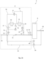
- Fig. 1A is a setup of a subsea system 1 according to the invention.
- the subsea system 1 as disclosed in Fig. 1 comprises a preconditioning arrangement 2 and a pressure boosting device 3.
- the pressure boosting device 3 having an operational window dictating operational parameter in terms of maximum and minimum allowable density of the process fluid entering the pressure boosting device, and wherein the preconditioning arrangement ensures that the process fluid is within the operational window of the pressure boosting device before entering the pressure boosting device 3.
- Other operational parameters such as temperature, pressure and flow of the pressure boosting device may also be limiting factors relevant for the operational window.
- the preconditioning arrangement 2 ensures that the process fluid entering the pressure boosting device 3 is within the operational window for the pressure boosting device 3 such that the pressure boosting device is not damaged by the process fluid.
- process fluid from e.g. a well enters the preconditioning arrangement subsea system 1 via an inlet pipe or process fluid pipe 45.
- the process fluid pipe direct the fluid to the main line 45.
- An on-off valve 51 direct the fluid to the coolers 20, 21 or bypass the coolers 20, 21.
- the branch line 50 comprises a first on-off valve 56 and a second on-off valve 57 arranged in series.
- a first cooler 20 is arranged downstream of the second on-off valve 57 and a second cooler 21 is arranged downstream of the first cooler 20.
- a temperature transmitter 23 control the temperature in the process fluid after exiting the first cooler 20.
- the temperature transmitter 23 is connected to a controller controlling a pump recirculation valve 66 arranged in a recirculation line 65 connected downstream of the pressure boosting device 3 via control lines 69.
- the controller manipulates the pump recirculation valve 66 to guarantee a minimum temperature by opening the pump recirculation valve 66 as will discussed in greater detail below.
- a first bypass line 58 is connected between the first and second on-off valves 56, 57 in one end thereof and between the first and second coolers in the other end thereof, thereby bypassing the first cooler 21.
- the bypass line 58 comprises an operated control valve 22 for guiding the flow in the bypass line 58 to the second cooler 21.
- the control valve 22 uses the temperature transmitter 23 to control the temperature in the process fluid in the pressure boosting device 3.
- An on-off valve 61 is arranged in the outlet line 60 of the second cooler 22.
- the outlet line 60 is connected to the main line 45 downstream of the on-off valve 51 in the main line 45 and upstream of the pressure boosting device 3.
- a recirculation line 65 is connected to the outlet line 64 downstream of the pressure boosting device 3 and the main line 45.
- An operable pump recirculation valve 66 is arranged in the recirculation line 65 to control minimum flow of the boosting device 3 and minimum temperature in the preconditioning arrangement 2.
- the pump recirculation valve 66 is connected to temperature transmitter 23 measuring temperature of the process fluid downstream of the first cooler 20 via control lines 69.
- the pump recirculation valve 66 is controlled by the temperature transmitter 23. If the temperature of the process fluid downstream of the first cooler 20 is low (e.g.
- the pump recirculation valve 66 opens thereby recirculating process fluid which has been pressurized by the pressure boosting device 3 into the preconditioning arrangement 2.
- the risk of hydrate formation resulting from reduced flow, and thereby reduced temperature of the process fluid exiting the first cooler is reduced.
- the recirculation loop 65 may be necessary if the process fluid has not reached satisfying temperature at the outlet of the first cooler 20.
- Fig. 1B is an example of a cooler system 4 forming part of the subsea system.
- the cooler system 4 comprises a connection to a process fluid line 45 or a branch line 50 as disclosed in the subsea system 1 in Fig. 1A .
- a first and second cooler 20, 21 are arranged in series where a passive cooler system is actively controlled by the pneumatically operated valve 22 which can be adjusted in order to adjust the amount of process fluid flowing through the bypass line 58.
- the amount of process fluid is thus dependent on the active control of the operated valve 22 and how much of the process fluid which flows through the bypass line 58.
- a chemical injection line 68 is connected to the process fluid line 45 upstream of the first cooler 20.
- the chemical injection line 68 could be connected downstream of the first cooler 20 but upstream of the second cooler 21.
- Fluid exiting the second cooler 21 is typically directed to or towards the pressure boosting device 3 (as shown in Fig. 1A ).
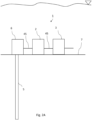
- Fig. 2A is an example of a subsea system 1 connected to a well 5, where the subsea system 1 is arranged on a seabed 7 and comprises a subsea tree 6, a preconditioning arrangement 2 and a pressure boosting device 3.
- the components of the subsea system 1 are fluidly connected to each other via a process fluid line/main line 45.
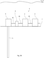
- Fig. 2B is an example of a subsea system 1 connected to a well 5, wherein the subsea system 1 is arranged on a seabed 7 and comprises a subsea tree 6, a separation device 8, a preconditioning arrangement 2 and a pressure boosting device 3.
- the separation device 8 serves to separate the process fluid before entering the preconditioning arrangement 2.
- the components of the subsea system 1 are fluidly connected to each other via a process fluid line/main line 45.
- Fig. 3A shows an example of a single cooler.
- the cooler is arranged in a subsea environment.
- the well flow i.e. process fluid flow, enters the cooler coil 10 in the upper part.
- the inflow direction is shown by arrow A.
- the well flow exits the cooler in a lower part.
- the outflow direction out of the coil 10 in the cooler is shown by arrow B.
- seawater enters from beneath the cooler (shown by arrow C in the figure) and escapes through the upper part of the cooler, shown by arrow D.
- On the upper end of the cooler it is arranged a first perforated plate 11 and second perforated plate 13, with perforations 12.
- the second perforated plate 13 is connected to the walls of the cooler.
- the first perforated plate 11 is movable and arranged in a parallel plane relative the second perforated plate 13.
- the movement of the first perforated plate 11 is for example conducted by means of an actuator 14, which actuator 14 is typically of a mechanical, electrical type etc.
- Fig. 3B shows a top view of an example of the configuration of the first perforated plate 11 being provided with perforations 12.
- Fig. 4 shows an example of a cooling system to be used with the invention, and in particular shows the cooler system as disclosed in Fig. 4 in WO 2013/174584 .
- the well flow enters the cooler system through inlet pipe 45.
- the flow direction is shown by arrow A.
- the flow exits the cooler system through outlet pipe 46.
- the flow direction is shown by arrow B.
- five branches 30, 31, 32, 33, 34 where the branches are all arranged in parallel with each other.
- At the inlet of each of the connection series 30, 31, 32, 33, 34 it is arranged a flow control device 36 controlling the inflow into each branch, and into each cooler.
- the flow control device 36 is typically a three-way valve or other means capable of directing a well flow.
- sensors such as temperature sensor, flow sensors, pressure sensors may be used.
- the sensors can be arranged at different positions in the cooler system, e.g. one at each cooler, between the coolers, at the inlet of a cooler series or branches etc.
- the flow control means 36 arranged at each inlet of a connection series, may direct the flow into one or more of the different series connections.
- series connection 31 is the cooling series that has the largest cooling capacity of the shown series connections, while series connection 33 has the lowest cooling capacity if excluding series connection 34.
- Connection 34 is a bypass line, allowing the flow to flow through the cooler system bypassing all the coolers.
- Fig. 5 shows a cooler system to be used with the subsea system, and particular shows the cooler system as disclosed in Fig. 5 in WO 2013/174584 .
- each cooler it may be arranged a bypass circuit 37, 38 bypassing at least parts of a fluid flow if, for instance, the temperature is above a threshold value.
- the bypass circuit 37, 38 may be by the form of a one-way flow loop as disclosed by reference numeral 37 or a two-way flow loop as shown by reference numeral 38.
- the system may in addition include all the features of the embodiment disclosed in Fig. 4 .
- the cooler system provides large flexibility with regards to the cooling requirement. Being able to provide a cooler system having different cooling capacities dependent on the cooling need, is advantageous bearing in mind that the hydrate formation temperature and/ or flow rates may vary during the lifetime of a field.
Landscapes
- Life Sciences & Earth Sciences (AREA)
- Engineering & Computer Science (AREA)
- Geology (AREA)
- Mining & Mineral Resources (AREA)
- Physics & Mathematics (AREA)
- Environmental & Geological Engineering (AREA)
- Fluid Mechanics (AREA)
- General Life Sciences & Earth Sciences (AREA)
- Geochemistry & Mineralogy (AREA)
- Fluid-Pressure Circuits (AREA)
Description
- The present invention relates to the field of subsea systems, and in particular to subsea systems comprising a preconditioning unit upstream of a pressure boosting device.
- As new oil and gas production wells are discovered and the old ones lower their production curve, or there is an increase in the production of other fluids (such as water or gas), different from oil, new challenges are faced in order to continue producing with high efficiency. Various technologies are under research and can be applied for the improvement of productivity. One of the applied technologies is the monophasic or multiphasic fluid pressure elevation system.
- These systems elevate the pressure of the fluids so that they can be transported to an oil rig, to an onshore location or to offshore production and/or processing units. Another application is to elevate the pressure through the utilization of subsea systems, and subsequently re-injecting them.
- With the use of these pressure elevation systems, challenges arise regarding the different types of fluids that can be used in these systems and the high pressure increases that they can be subjected to. One consequence of the increase in fluid pressure is the increase in temperature.
- This increase in temperature in the fluid is proportional to the increase in pressure. Thus, the greater the pressure gain of the system, the greater its increase in temperature.
- Due to these characteristics, the demand for subsea heat exchangers such as coolers may be required in these pressure elevation systems.
- The subsea cooling system for hydrocarbons is an increasingly current demand for various applications in fluid conditioning in order to: meet flexible duct requirements, improve the efficiency of machines and adjust the fluid for the best separation conditions.
- Currently, many solutions exist in which heat exchange subsea is used to adjust the process fluid using the thermal exchange with seawater. In the current scenario, heat exchange systems are divided into two different types of systems: active and passive.
- In a passive subsea heat exchanger, the process fluid passes through tubes in which the heat exchange occurs with the seawater, simply using the principle of thermal conduction. In this case, there is no active form of controlling the thermal exchange.
- For the active heat exchangers, the principle of thermal convection is also used to improve and/or control the thermal exchange. The principle of convection is used by controlling the flow of seawater. This control of marine currents can be carried out by increasing the marine flow in the vicinity of the heat exchanger through systems that increase the marine current. Another strategy used for the system is to reduce the marine current, when necessary, to control the temperature of the heat exchanger.
-
WO 2013/174584 A1 relates to a subsea cooler system for active control of passive coolers. The subsea cooler system comprising at least a first and a second cooler arranged in a series connection, and a third cooler arranged in parallel with said first and second coolers. At least one of said coolers comprises a recirculation loop. -
WO 2014/049024 A2 relates to a heat exchanger system that includes an inlet and an outlet for a first fluid and a heat exchanger between the inlet and the outlet wherein the first fluid circulates, wherein the heat exchanger comprises at least one deflector to guide the flow of a second fluid. A method is also described to exchange heat between a first and a second fluid using free convection velocity field to create forced convection in the heat exchanger of a heat exchanger system. A method to exchange heat between a first and a second fluid comprising providing a heat exchanger system between the first and the second fluids, said heat exchanger system comprising a heat exchanger wherein the first fluid circulates and increasing the flow turbulences of a second fluid around the heat exchanger. - There are however drawbacks related to the prior art solutions above, because all required parameters of the process fluid exiting the cooler system is not known, resulting in a potential risk of damaging any equipment downstream of the cooler system.
- One of the objectives of this invention is thus to provide a subsea system which ensures that the process fluid entering a pump or pressure boosting device has fluid characteristics that will not damage the equipment.
- The invention is set forth in the independent claims, while the dependent claims describe other characteristics of the invention.
- Using a passive cooler with a secondary line for controlling the temperature of the process fluid, renders it possible to control the outlet temperature of the process fluid exiting the cooler in a way that the thermal load at the inlet of the cooler can be varied. This control adjusts the process fluid for the overall cooler system's outlet condition without the need to add new rotary equipment and consequently increasing the number of failure points.
- The process fluid preconditioning system on the suction, i.e. upstream, of the pressure boosting device aims to guarantee the pressure boosting device operation, maintaining the temperature at the discharge, i.e. upstream, of pressure boosting device and any interstage of this device, in accordance with system requirements in terms of at least density and minimum temperature requirements.
- The invention relates to a subsea system connected to a subsea well for boosting a process fluid flowing out of the well, comprising:
- a preconditioning arrangement connectable to a process fluid line from a well, wherein the preconditioning arrangement comprises:
- o at least one sensor for measuring temperature and one sensor for measuring pressure of the process fluid,
- o means for estimating density of the process fluid based on measured temperature and pressure,
- o a cooler system comprising at least a first cooler for cooling the process fluid, wherein the first cooler comprises a bypass line for guiding a portion of the process fluid therethrough and wherein the bypass line comprises a control valve for varying the amount of process fluid flowing therethrough and a temperature control unit for measuring a temperature in the process fluid in the bypass line,
- a pressure boosting device arranged downstream of the preconditioning arrangement and wherein the pressure boosting device comprises an inlet for receiving a process fluid with at least 30 volume percentage of CO2 at operational subsea conditions and an outlet for discharge of pressurized process fluid, the pressure boosting device having an operational window dictating operational parameter in terms of maximum and minimum allowable density of the process fluid entering the pressure boosting device, and wherein the preconditioning arrangement ensures that the process fluid is within the operational window of the pressure boosting device before entering the pressure boosting device.
- The sensors used for measuring temperature and pressure may be standard temperature and pressure sensors used subsea. The sensors may be arranged at the outlet of the cooler(s) or they can be arranged elsewhere in the preconditioning arrangement.
- Normally, the composition of the process fluid is known either by taking a sample and or from measurements from e.g. a multiphase meter etc. Although the composition of the process fluid, e.g. water-cut etc., varies with time, the changes on a day-to-day or month-to-month basis is normally insignificant. Thus, it is not common practice to perform real tests of the process fluid composition too often. The means for estimating maximum and minimum allowable density of the process fluid may then be a pre-made diagram for the specific process fluid for this subsea well where density can be read based on the measured temperature and pressure. The maximum and minimum allowable density may be decided based on parameters such as, in addition to temperature, pressure and composition of the process fluid, hydrate formation temperature.
- The cooler system provides for thermal exchange between the process fluid and the surrounding seawater and can be of the type described in
WO2013/174584 . - The system can have two or more stages of thermal exchange. Each of these parameters contemplates cooling tubes, where the heat transfer occurs between the process fluid and the seawater. These coolers can be organized in series and/or in parallel allowing different scenarios and modes of operation to be attended.
- The cooler system may comprise one or more coolers. Each cooler may be composed of parallel tubes, forming horizontal sections. The number of horizontal sections and the length of each section is determined in accordance with the value of maximum design thermal load at the inlet of the cooler.
- In the design of the preconditioning system, the cooler system/cooling stages can be aligned in series and/or parallel. The design of the cooler system can be such that the different cooling stages have different cooling capacity.
- Each or some of the coolers may comprise a bypass line that permits that part of the fluid is diverted from the cooler and allowed to enter the bypass line instead. This deviation is accomplished through the manipulation of the control valve present in this bypass line. The amount of process fluid flowing in the bypass line is determined in order to meet the criteria of specific temperature in the system.
- The flow that was deviated from the cooler through the bypass line is preferably mixed with the flow coming from the cooler downstream of the cooler, in which a thermal equilibrium is obtained at the outlet of the cooler. The greater the flow that passes through the bypass line, the higher the equilibrium temperature of the system.
- The process fluid is preferably a so-called dense gas, which is a natural gas rich in CO2. This gas has a composition similar to the natural gas produced in Brazilian Pre-Salt well fields, with a high-density value as a differential, similar to fluids in the liquid state. The process fluid comprises at least 30 volume percentage of CO2 at operational subsea conditions, i.e. at the conditions where the pressure boosting device is arranged. Additionally, typical characteristic parameters for the process fluid is in the range of:
- density 200kg/m3 to 700kg/m3;
- 30% to 90% of CO2 by volume (volume percentage);
- 60bar to 400bar, and
- 0°C to 120°C .
- The density or specific mass of the process fluid varies dependent on the pressure and temperature. Simulations carried out with different temperatures for the process fluid verified that if reducing the temperature, the density of the process fluid increases. Specific mass values lower than 260 kg/m3 make it impossible to utilize the pressure boosting device, in which fluid preconditioning is necessary, reducing the temperature in a controlled manner, reaching the value of specific mass that permits operation of the pressure boosting device.
- In addition to dictating operational parameter in terms of maximum and minimum allowable density, the operational window may have at least maximum and minimum operational parameters of pressure and temperature.
- This system may be arranged downstream a separation device. The process fluid flowing through the subsea system may be re-injected into a reservoir. Therefore, another determining factor for the parameters of this system may be the temperature limit in the injection lines used to inject the process fluid discharged from the pressure boosting device. In certain operating modes, the temperature at the discharge of the pressure boosting will change, requiring a fluid preconditioning system at its suction, adjusting the temperature of the discharge. The preconditioning arrangement of the subsea system will enable the operation of the pressure boosting device, in addition to keeping the required temperature allowed by the injection line.
- The bypass lines containing their respective control valves, can be added to allow for an active temperature control at the outlet of each cooler stage of the preconditioning system.
- When the demand for thermal load required by the process fluid is reduced, it is necessary to manipulate the bypass line control valve. Then a larger portion of the process fluid is guided or deviated through the bypass line resulting in less decrease in temperature (compared to guiding all process fluid through the cooler) and thus less increase in the density of the process fluid (compared to guiding all process fluid through the cooler resulting in an even lower temperature). In this way, if operating on the limit of the minimum acceptable density for the process fluid, the required specific mass value is obtained such that the process fluid can enter the pressure boosting device.
- The proposed active temperature control system, besides guaranteeing the specific mass or density required in the system output, also acts in the prevention of hydrate at each cooler. The prevention of hydrate formation in the cooler(s), may be achieved using a temperature controller that manipulate the recirculation line of the pressure boosting device.
- The active control described above, can be applied in natural and/or forced convection heat transfer process. This control linked to the diverse possibilities of stage arrangements, guaranties the possibility of the preconditioning system attending a large variety of work temperature at any point of the system.
- The system is designed to attend the process fluid's maximum thermal load. In this condition, i.e. at maximum thermal load, 100% of the flow will pass through the coolers by the main line and the control valves of the bypass lines will be closed.
- This invention enables the subsea dense gas pressurization system and the subsequent re-injection of the process fluid into a reservoir.
- The system can be installed at a depth of up to 3,000 meters.
- The main cooler inlet line may be specified in order to attend a uniform distribution between all tubes connected to it. This configuration enables uniform distribution between all the parallel process fluid tubes entering into the cooler, without causing preferential flow.
- The main cooler outlet line may be specified in order to attend a uniform distribution between all tubes connected to it. This configuration enables uniform distribution between all the parallel process fluid tubes that exit the cooler, resulting in a uniform mixture of the process fluid entering the pressure boosting device.
- An additional control valve or restriction orifice may be positioned in the suction, i.e. upstream, or discharge, i.e. downstream, of the cooler, performing the pressure equalization.
- The subsea system may comprise a recirculation loop connected downstream of the pressure boosting device and upstream of the preconditioning arrangement. The recirculation loop may comprise a pump recirculation valve which is connected to a temperature transmitter measuring temperature of the process fluid downstream of the first cooler. The pump recirculation valve may be controlled by the temperature transmitter downstream of the first cooler. If the temperature of the process fluid downstream of the first cooler is low (e.g. due to reduced flow from the well) with the risk of hydrate formation in the cooler(s), the pump recirculation valve opens thereby recirculating process fluid which has been pressurized by the pressure boosting device into the preconditioning arrangement. As such, the risk of hydrate formation resulting from reduced flow, and thereby reduced temperature of the process fluid exiting the first cooler, is reduced. I.e. the recirculation loop may be necessary if the process fluid has not reached satisfying temperature at the outlet of the first cooler.
- In an aspect, the cooler system comprises a second cooler arranged in series or parallel connection with the first cooler. The second cooler may have equal, higher or lower cooling capacity than the first cooler.
- In an aspect, the cooler system comprises a third cooler which is arranged in parallel connection with the first and second cooler. If the first and second coolers are arranged in series, and the third cooler in parallel, there is a total of two cooling branches, whereas if the first, second and third coolers are in parallel connection, there is a total of three cooling branches. The different cooling branches preferably have different cooling capacity such that different cooling requirements or cooling demands may be met without modifying the system.
- The cooler system may comprise at least one flow control device, e.g. a valve, for directing flow through at least one of the cooling branches dependent on the cooling requirement.
- In an aspect, some or all the coolers may comprise a recirculation loop for recirculating process fluid back into an inlet of the cooler.
- In an aspect, some or all the coolers may comprise a chemical injection line. The preconditioning system presents the possibility of inserting a chemical injection point at the inlet of each cooling stage. The point of injection allows for the complete distribution of chemicals added to all the cooler's tubes. The chemical injection fluid can be Mono Ethylene Glycol (MEG) and this chemical injection fluid can be injected into the cooler if there is a risk that hydrates may form in the cooler, e.g. in the tubes forming the cooler. Each of the coolers may have a chemical injection line to prevent the formation of hydrates in operation and for preservation with no flow.
- The subsea system may include an active control system of the temperature, complementary to the arrangement of the cooler stages. This control system makes it possible to obtain the specific mass required at the outlet of the preconditioning arrangement in addition to potentially prevent hydrate formation. This control system utilizes subsea temperature transmitters for monitoring temperatures in real time.
- It is further described a of operating a subsea system, the subsea system comprises:
- a pressure boosting device comprises an inlet for receiving a process fluid with at least 30 volume percentage of CO2 at operational subsea conditions and an outlet for discharge of pressurized process fluid, the pressure boosting device having an operational window dictating operational parameter in terms of maximum and minimum allowable density of the process fluid entering the pressure boosting device;
- a preconditioning arrangement for handling the process fluid, wherein the preconditioning arrangement is arranged upstream of the inlet of the pressure boosting device, and wherein the preconditioning arrangement is connectable to a process fluid line from a well and wherein the preconditioning arrangement comprises:
- one sensor for measuring temperature and one sensor for measuring pressure of the process fluid,
- a cooler system comprising at least a first cooler, and wherein the method comprises the steps of:
- measuring parameters of the process fluid entering the preconditioning arrangement using the sensors;
- determine whether any of the parameters are outside an operational window of the pressure boosting device;
- decide whether any action is required by the preconditioning arrangement in order for the density of the process fluid to be within the operational window of the pressure boosting device, and
- when any required actions are taken in order for the density of the process fluid to be within the operational window of the pressure boosting device, allowing the process fluid to enter the pressure boosting device thereby ensuring that the process fluid is within the operational window of the pressure boosting device before entering the pressure boosting device.
- The operational parameters which is measured and estimated in the method, may be density pressure and/or temperature and is dictated by the operational window of the pressure boosting device.
- The system uses an active control of the temperature, complementary to the arrangement of the cooling stages. This control makes it possible to obtain the specific mass required at the outlet of the system, and the prevention of hydrate formation.
- This control system utilizes subsea temperature transmitters for monitoring temperatures in real time.
- Summarized, the subsea system and method may have at least one of the following advantages:
- New rotary equipment and consequently increasing the number of failure points is avoided.
- The process fluid preconditioning system on the suction of the pressure boosting device aims to guarantee its operation, maintaining the temperature at the discharge of the pressure boosting device adequate to the system requirements,
- Preconditioning the process fluid on the suction of the pressure boosting device enables its operation, in the operational modes where the fluid temperature increases and in normal operation, where the reservoir fluid does not have adequate specific mass for the operation of this pressure boosting device.
- These and other embodiments of the present invention will be apparent from the attached drawings, where:
-
-
Fig. 1A is a setup of a subsea system according to the invention; -
Fig. 1B is an example of a cooler system forming part of the subsea system; -
Fig. 2A is an example of a subsea system connected to a well, wherein the subsea system comprises a subsea tree, a preconditioning arrangement and a pressure boosting device; -
Fig. 2B is an example of a subsea system connected to a well, wherein the subsea system comprises a subsea tree, a separation device, a preconditioning arrangement and a pressure boosting device; -
Fig. 3A shows a side-view of a cooler which can form part of the subsea system; -
Fig 3B shows a top view of a perforated plate of a single cooler; -
Fig. 4 shows a cooler system as illustrated inFig. 4 inWO 2013/174584 comprising five parallel cooler series, where some of the coolers are provided with a recirculation loop; -
Fig. 5 shows a cooler system as illustrated inFig. 5 WO 2013/174584 , where some of the coolers are provided with a recirculation loop and a bypass loop; - In the following, embodiments of the invention will be discussed in more detail with reference to the appended drawings. It should be understood, however, that the drawings are not intended to limit the invention to the subject-matter depicted in the drawings.
-
Fig. 1A is a setup of asubsea system 1 according to the invention. Thesubsea system 1 as disclosed inFig. 1 comprises apreconditioning arrangement 2 and apressure boosting device 3. Thepressure boosting device 3 having an operational window dictating operational parameter in terms of maximum and minimum allowable density of the process fluid entering the pressure boosting device, and wherein the preconditioning arrangement ensures that the process fluid is within the operational window of the pressure boosting device before entering thepressure boosting device 3. Other operational parameters such as temperature, pressure and flow of the pressure boosting device may also be limiting factors relevant for the operational window. Thepreconditioning arrangement 2 ensures that the process fluid entering thepressure boosting device 3 is within the operational window for thepressure boosting device 3 such that the pressure boosting device is not damaged by the process fluid. - In operation, process fluid from e.g. a well (not shown in
Fig. 1A ) enters the preconditioning arrangementsubsea system 1 via an inlet pipe or processfluid pipe 45. In thepreconditioning arrangement 2 the process fluid pipe direct the fluid to themain line 45. An on-offvalve 51, direct the fluid to thecoolers coolers branch line 50 comprises a first on-offvalve 56 and a second on-offvalve 57 arranged in series. Afirst cooler 20 is arranged downstream of the second on-offvalve 57 and asecond cooler 21 is arranged downstream of thefirst cooler 20. Atemperature transmitter 23 control the temperature in the process fluid after exiting thefirst cooler 20. Thetemperature transmitter 23 is connected to a controller controlling apump recirculation valve 66 arranged in arecirculation line 65 connected downstream of thepressure boosting device 3 via control lines 69. In case of risk of hydrate formation, the controller manipulates thepump recirculation valve 66 to guarantee a minimum temperature by opening thepump recirculation valve 66 as will discussed in greater detail below. Afirst bypass line 58 is connected between the first and second on-offvalves first cooler 21. Thebypass line 58 comprises an operatedcontrol valve 22 for guiding the flow in thebypass line 58 to thesecond cooler 21. Thecontrol valve 22 uses thetemperature transmitter 23 to control the temperature in the process fluid in thepressure boosting device 3. An on-offvalve 61 is arranged in theoutlet line 60 of thesecond cooler 22. Theoutlet line 60 is connected to themain line 45 downstream of the on-offvalve 51 in themain line 45 and upstream of thepressure boosting device 3. - A
recirculation line 65 is connected to theoutlet line 64 downstream of thepressure boosting device 3 and themain line 45. An operablepump recirculation valve 66 is arranged in therecirculation line 65 to control minimum flow of the boostingdevice 3 and minimum temperature in thepreconditioning arrangement 2. Thepump recirculation valve 66 is connected totemperature transmitter 23 measuring temperature of the process fluid downstream of thefirst cooler 20 via control lines 69. Thepump recirculation valve 66 is controlled by thetemperature transmitter 23. If the temperature of the process fluid downstream of thefirst cooler 20 is low (e.g. due to reduced flow from the well) with the risk of hydrate formation in the cooler(s) 20, 21, thepump recirculation valve 66 opens thereby recirculating process fluid which has been pressurized by thepressure boosting device 3 into thepreconditioning arrangement 2. As such, the risk of hydrate formation resulting from reduced flow, and thereby reduced temperature of the process fluid exiting the first cooler, is reduced. I.e. therecirculation loop 65 may be necessary if the process fluid has not reached satisfying temperature at the outlet of thefirst cooler 20. -
Fig. 1B is an example of acooler system 4 forming part of the subsea system. thecooler system 4 comprises a connection to aprocess fluid line 45 or abranch line 50 as disclosed in thesubsea system 1 inFig. 1A . In thecooler system 4 ofFig. 1B a first andsecond cooler valve 22 which can be adjusted in order to adjust the amount of process fluid flowing through thebypass line 58. - The operational conditions of the disclosed cooler system in terms of cooling capacity is as follows:
- 1) operated
valve 22 closed: all process fluid flow through first andsecond coolers - 2) operated
valve 22 fully open and on-offvalve 57 closed: all process fluid flows through thebypass line 58 and into thesecond cooler 21 only = minimum cooling capacity, - 3) operated
valve 22 partly open: some process fluid flows through thebypass line 58 = medium cooling capacity. - The amount of process fluid is thus dependent on the active control of the operated
valve 22 and how much of the process fluid which flows through thebypass line 58. - A
chemical injection line 68 is connected to theprocess fluid line 45 upstream of thefirst cooler 20. Alternatively, thechemical injection line 68 could be connected downstream of thefirst cooler 20 but upstream of thesecond cooler 21. - Fluid exiting the
second cooler 21 is typically directed to or towards the pressure boosting device 3 (as shown inFig. 1A ). -
Fig. 2A is an example of asubsea system 1 connected to awell 5, where thesubsea system 1 is arranged on aseabed 7 and comprises asubsea tree 6, apreconditioning arrangement 2 and apressure boosting device 3. The components of thesubsea system 1 are fluidly connected to each other via a process fluid line/main line 45. -
Fig. 2B is an example of asubsea system 1 connected to awell 5, wherein thesubsea system 1 is arranged on aseabed 7 and comprises asubsea tree 6, aseparation device 8, apreconditioning arrangement 2 and apressure boosting device 3. Theseparation device 8 serves to separate the process fluid before entering thepreconditioning arrangement 2. The components of thesubsea system 1 are fluidly connected to each other via a process fluid line/main line 45. -
Fig. 3A shows an example of a single cooler. In the exemplified cooler, the cooler is arranged in a subsea environment. The well flow, i.e. process fluid flow, enters thecooler coil 10 in the upper part. The inflow direction is shown by arrow A. The well flow exits the cooler in a lower part. The outflow direction out of thecoil 10 in the cooler is shown by arrow B. Preferably, seawater enters from beneath the cooler (shown by arrow C in the figure) and escapes through the upper part of the cooler, shown by arrow D. On the upper end of the cooler it is arranged a firstperforated plate 11 and secondperforated plate 13, withperforations 12. The secondperforated plate 13 is connected to the walls of the cooler. The firstperforated plate 11 is movable and arranged in a parallel plane relative the secondperforated plate 13. The movement of the firstperforated plate 11 is for example conducted by means of anactuator 14, which actuator 14 is typically of a mechanical, electrical type etc. By arranging the first perforated 11 plate movable relatively the secondperforated plate 13, it is possible to adjust the flow of seawater through the cooler, as the cooling of the well flow is driven by natural convection. The well flow, having a high temperature, enters thecoil 10 in the cooler at arrow A and is heat-exchanged with seawater that has already been heated by the well flow in the lower part of the cooler. Therefore, the well flow experiences a graduated cooling, i.e. first it is exposed to heated seawater, then it is exposed to cold seawater. The heated seawater will move within the cooler, in this case it arises. Due to the convection, the heated seawater travels to a relatively colder area. -
Fig. 3B shows a top view of an example of the configuration of the firstperforated plate 11 being provided withperforations 12. A movement of the firstperforated plate 11 relative the secondperforated plate 13, controls the flow area through the perforations of the first and second perforated plates, i.e. the convective flow rate, of seawater flowing through the cooler. -
Fig. 4 shows an example of a cooling system to be used with the invention, and in particular shows the cooler system as disclosed inFig. 4 inWO 2013/174584 . The well flow enters the cooler system throughinlet pipe 45. The flow direction is shown by arrow A. The flow exits the cooler system throughoutlet pipe 46. The flow direction is shown by arrow B. In the figure it is shown fivebranches connection series flow control device 36 controlling the inflow into each branch, and into each cooler. Theflow control device 36 is typically a three-way valve or other means capable of directing a well flow. Additionally, sensors such as temperature sensor, flow sensors, pressure sensors may be used. The sensors can be arranged at different positions in the cooler system, e.g. one at each cooler, between the coolers, at the inlet of a cooler series or branches etc. Dependent on required cooling capacity, the flow control means 36, arranged at each inlet of a connection series, may direct the flow into one or more of the different series connections. In the exemplified embodiment,series connection 31 is the cooling series that has the largest cooling capacity of the shown series connections, whileseries connection 33 has the lowest cooling capacity if excludingseries connection 34.Connection 34 is a bypass line, allowing the flow to flow through the cooler system bypassing all the coolers. -
Fig. 5 shows a cooler system to be used with the subsea system, and particular shows the cooler system as disclosed inFig. 5 inWO 2013/174584 . In connection with each cooler, it may be arranged abypass circuit bypass circuit reference numeral 37 or a two-way flow loop as shown byreference numeral 38. The system may in addition include all the features of the embodiment disclosed inFig. 4 . - The cooler system provides large flexibility with regards to the cooling requirement. Being able to provide a cooler system having different cooling capacities dependent on the cooling need, is advantageous bearing in mind that the hydrate formation temperature and/ or flow rates may vary during the lifetime of a field.
- The invention is defined by the features specified in the appended claims.
-
1 Subsea system 45 Inlet pipe/process fluid line/ main line 2 Preconditioning arrangement 46 Outlet pipe 3 Pressure boosting device 50 Branch line 4 Cooler system 51 Pressure control valve (main line) / on-off valve 5 well 53 Pressure transmitter (main line) 6 Subsea tree 54 Temperature transmitter (main line) 7 Seabed 55 Flow transmitter 8 Separation device 56 First pressure control valve (branch line) / on-off valve 10 Cooler coil 57 Second pressure control valve (branch line)/on-off valve 11 First perforated plate 58 First bypass line 12 perforations 59 Second bypass line 13 Second perforated plate 60 Outlet line 14 actuator 61 Pressure control valve (outlet line)/ on-off valve 20 First cooler 63 Check valve 21 Second cooler 64 Outlet line (pressure boosting device) 22 operated valve/on-off valve 65 Recirculation line / recirculation loop 23 Temperature transmitter 66 pump recirculation valve 24 Second bypass line 68 Chemical injection line 30, 31, 32, 33, 34 branches 69 Control lines 36 Flow control device A, B, C, D Direction of flow 37, 38 Bypass circuit
Claims (11)
- Subsea system (1) connected to a subsea well (5) for boosting a process fluid flowing out of the well (5), comprising:- a preconditioning arrangement (2) connectable to a process fluid line (45) from a well (5), wherein the preconditioning arrangement (2) comprises:wherein the subsea system (1) further comprises:o at least one sensor (54) for measuring temperature and one sensor (53) for measuring pressure of the process fluid,o means for estimating density of the process fluid based on measured temperature and pressure,o a cooler system (4) comprising at least a first cooler (20) for cooling the process fluid, wherein the first cooler (20) comprises a bypass line (58) for guiding a portion of the process fluid therethrough and wherein the bypass line (58) comprises a control valve (22) for varying the amount of process fluid flowing therethrough and a temperature control unit (64) for measuring a temperature in the process fluid in the bypass line (58),- a pressure boosting device (3) arranged downstream of the preconditioning arrangement (2) and wherein the pressure boosting device (3) is characterized in that it comprises an inlet (45) for receiving a process fluid with at least 30 volume percentage of CO2 at operational subsea conditions and an outlet (46) for discharge of pressurized process fluid, the pressure boosting device (3) having an operational window dictating operational parameter in terms of maximum and minimum allowable density of the process fluid entering the pressure boosting device (3), and wherein the preconditioning arrangement (2) ensures that the process fluid is within the operational window of the pressure boosting device (3) before entering the pressure boosting device (3).
- The subsea system (1) according to claim 1, wherein the operational window has at least maximum and minimum operational parameters of pressure and temperature.
- The subsea system (1) according to any of the preceding claims, wherein the subsea system (1) further comprises a recirculation loop (65) connected downstream of the pressure boosting device (3) and upstream of the preconditioning arrangement (2).
- The subsea system (1) according to any of the preceding claims, wherein the cooler system (4) comprises a second cooler (21) arranged in series or parallel connection with the first cooler (20).
- The subsea system (1) according to claim 4, wherein the cooler system (4) comprises a third cooler which is arranged in parallel connection with the first and second cooler (20,21).
- The subsea system (1) according to any of the preceding claims, wherein the cooler system (4) comprises at least one flow control device (36) for directing flow through at least one cooler (20, 21).
- The subsea system (1) according to any of the preceding claims, wherein at least one of the coolers (20,21) comprises a recirculation loop (35) for recirculating process fluid back into an inlet of the cooler (20,21).
- The subsea system (1) according to any of claims 4 or 5, or any of claims 6 or 7 when dependent upon claim 4 or 5, wherein at least two of the coolers (20,21) have different cooling capacity.
- The subsea system (1) according to any of the preceding claims, wherein the first cooler (20) comprises a chemical injection line (68).
- The subsea system (1) according to any of the preceding claims, further comprising a recirculation loop (65) connected downstream of the pressure boosting device (3) and upstream of the preconditioning arrangement (2), wherein the recirculation loop (65) comprises a pump recirculation valve (66) which is connected to a temperature transmitter (23) measuring temperature of the process fluid downstream of the first cooler (20), and wherein the pump recirculation valve (66) is controlled by the temperature transmitter (23).
- Method of operating a subsea system (1), the subsea system (1) comprises:- a pressure boosting device (3) comprises an inlet (45) for receiving a process fluid with at least 30 volume percentage of CO2 at operational subsea conditions and an outlet (46) for discharge of pressurized process fluid, the pressure boosting device (3) having an operational window dictating operational parameter in terms of maximum and minimum allowable density of the process fluid entering the pressure boosting device (3);- a preconditioning arrangement (2) for handling the process fluid, characterized in that the preconditioning arrangement (2) is arranged upstream of the inlet (45) of the pressure boosting device (3), and wherein the preconditioning arrangement (2) is connectable to a process fluid line (45) from a well (5) and wherein the preconditioning arrangement (2) comprises:at least one sensor (54) for measuring temperature and one sensor (53) for measuring pressure of the process fluid,a cooler system (4) comprising at least a first cooler (20), and wherein the method comprises the steps of:- measuring parameters of the process fluid entering the preconditioning arrangement (2) using the sensors (54,53);- determine whether any of the parameters are outside an operational window of the pressure boosting device (3);- decide whether any action is required by the preconditioning arrangement (2) in order for the density of the process fluid to be within the operational window of the pressure boosting device (3), and- when any required actions are taken in order for the density of the process fluid to be within the operational window of the pressure boosting device (3), allowing the process fluid to enter the pressure boosting device (3) thereby ensuring that the process fluid is within the operational window of the pressure boosting device (3) before entering the pressure boosting device (3).
Applications Claiming Priority (1)
| Application Number | Priority Date | Filing Date | Title |
|---|---|---|---|
| PCT/IB2020/058152 WO2022049407A1 (en) | 2020-09-02 | 2020-09-02 | A subsea system comprising a preconditioning unit and pressure boosting device and method of operating the preconditioning unit |
Publications (2)
| Publication Number | Publication Date |
|---|---|
| EP4208622A1 EP4208622A1 (en) | 2023-07-12 |
| EP4208622B1 true EP4208622B1 (en) | 2024-07-31 |
Family
ID=72670760
Family Applications (1)
| Application Number | Title | Priority Date | Filing Date |
|---|---|---|---|
| EP20781610.9A Active EP4208622B1 (en) | 2020-09-02 | 2020-09-02 | A subsea system comprising a preconditioning unit and pressure boosting device and method of operating the preconditioning unit |
Country Status (3)
| Country | Link |
|---|---|
| US (1) | US12410684B2 (en) |
| EP (1) | EP4208622B1 (en) |
| WO (1) | WO2022049407A1 (en) |
Families Citing this family (1)
| Publication number | Priority date | Publication date | Assignee | Title |
|---|---|---|---|---|
| CN118434106B (en) * | 2024-07-03 | 2024-09-06 | 西安交通大学 | Self-adaptive phase change cooling system for spacecraft electronic device |
Citations (1)
| Publication number | Priority date | Publication date | Assignee | Title |
|---|---|---|---|---|
| WO2013174584A1 (en) * | 2012-05-24 | 2013-11-28 | Fmc Kongsberg Subsea As | Active control of subsea coolers |
Family Cites Families (8)
| Publication number | Priority date | Publication date | Assignee | Title |
|---|---|---|---|---|
| US8011451B2 (en) * | 2007-10-19 | 2011-09-06 | Shell Oil Company | Ranging methods for developing wellbores in subsurface formations |
| NO339227B1 (en) | 2012-06-26 | 2016-11-21 | Aker Subsea As | Heat recovery from well flow |
| GB2503927B (en) | 2012-07-13 | 2019-02-27 | Framo Eng As | Method and apparatus for removing hydrate plugs in a hydrocarbon production station |
| WO2014049024A2 (en) | 2012-09-25 | 2014-04-03 | Framo Engineering As | Subsea heat exchanger |
| BR112017014040B1 (en) * | 2014-12-29 | 2022-05-03 | Aker Solutions As | Subsea fluid processing system and method of processing a well stream stream |
| US10463990B2 (en) * | 2015-12-14 | 2019-11-05 | General Electric Company | Multiphase pumping system with recuperative cooling |
| US10830016B2 (en) * | 2016-10-19 | 2020-11-10 | Onesubsea Ip Uk Limited | Regulating the temperature of a subsea process flow |
| US11713258B2 (en) * | 2017-08-24 | 2023-08-01 | Katz Water Tech, Llc | Apparatus system and method to extract minerals and metals from water |
-
2020
- 2020-09-02 EP EP20781610.9A patent/EP4208622B1/en active Active
- 2020-09-02 WO PCT/IB2020/058152 patent/WO2022049407A1/en not_active Ceased
- 2020-09-02 US US18/024,243 patent/US12410684B2/en active Active
Patent Citations (1)
| Publication number | Priority date | Publication date | Assignee | Title |
|---|---|---|---|---|
| WO2013174584A1 (en) * | 2012-05-24 | 2013-11-28 | Fmc Kongsberg Subsea As | Active control of subsea coolers |
Also Published As
| Publication number | Publication date |
|---|---|
| BR112023003883A2 (en) | 2023-04-04 |
| WO2022049407A1 (en) | 2022-03-10 |
| US20230287763A1 (en) | 2023-09-14 |
| US12410684B2 (en) | 2025-09-09 |
| EP4208622A1 (en) | 2023-07-12 |
Similar Documents
| Publication | Publication Date | Title |
|---|---|---|
| US10161554B2 (en) | Active control of subsea coolers | |
| KR101456338B1 (en) | Compressor assemblies and methods to minimize venting of a process gas during startup operations | |
| US9769954B2 (en) | Liquid cooling system for a computer cabinet | |
| KR101585948B1 (en) | Air conditioner | |
| JP5156929B2 (en) | Cryogenic fluid heating / vaporizing device and operation method thereof | |
| CN110411738B (en) | A modular valve flow and flow resistance testing system and testing method | |
| CN215492487U (en) | Test platform of supercritical carbon dioxide printed circuit board type heat exchanger | |
| US12410684B2 (en) | Subsea system comprising a preconditioning unit and pressure boosting device and method of operating the preconditioning unit | |
| CN119697958A (en) | Liquid cooling distribution unit, liquid cooling system and adjustment method | |
| CN114375382A (en) | Heat recovery device | |
| CN114501955B (en) | A self-circulating liquid cooling system and control method | |
| JP2013083379A (en) | Water inlet/outlet temperature difference control system, method of inspecting draining path, and method of inspecting water intake path | |
| CN216347146U (en) | Pressure Maintenance Systems for CO2 Refrigeration | |
| BR112023003883B1 (en) | Submarine system comprising a pre-conditioning unit and pressure-boosting device and method of operation of the pre-conditioning unit. | |
| CN115479789B (en) | A performance test platform for supercritical carbon dioxide printed circuit board heat exchangers | |
| CN106885390A (en) | Cryogenic Refrigeration System with Pulse Tube Expander | |
| CN220187532U (en) | Cooling medium circulation's accuse temperature system | |
| CN119738155B (en) | Valve test system and test method | |
| CN117472109A (en) | Interstage temperature control system to prevent liquefaction during high-pressure compression of CO2 mixed gas and its control method | |
| CN224094664U (en) | Gun line condenser pipe protection device based on electronic valve | |
| CN217844438U (en) | External water cooling circulation system | |
| EP4269148A1 (en) | A heat exchange system and a method of operating the same | |
| CN117552956A (en) | A supercritical CO2 compressor interstage temperature control system and method | |
| CN119045572B (en) | Temperature regulation and control system, test equipment and temperature regulation and control method | |
| CN120466571A (en) | Low-temperature gas generation system and method for simulating low-temperature environment experiments |
Legal Events
| Date | Code | Title | Description |
|---|---|---|---|
| STAA | Information on the status of an ep patent application or granted ep patent |
Free format text: STATUS: UNKNOWN |
|
| STAA | Information on the status of an ep patent application or granted ep patent |
Free format text: STATUS: THE INTERNATIONAL PUBLICATION HAS BEEN MADE |
|
| PUAI | Public reference made under article 153(3) epc to a published international application that has entered the european phase |
Free format text: ORIGINAL CODE: 0009012 |
|
| STAA | Information on the status of an ep patent application or granted ep patent |
Free format text: STATUS: REQUEST FOR EXAMINATION WAS MADE |
|
| 17P | Request for examination filed |
Effective date: 20230317 |
|
| AK | Designated contracting states |
Kind code of ref document: A1 Designated state(s): AL AT BE BG CH CY CZ DE DK EE ES FI FR GB GR HR HU IE IS IT LI LT LU LV MC MK MT NL NO PL PT RO RS SE SI SK SM TR |
|
| DAV | Request for validation of the european patent (deleted) | ||
| DAX | Request for extension of the european patent (deleted) | ||
| GRAP | Despatch of communication of intention to grant a patent |
Free format text: ORIGINAL CODE: EPIDOSNIGR1 |
|
| STAA | Information on the status of an ep patent application or granted ep patent |
Free format text: STATUS: GRANT OF PATENT IS INTENDED |
|
| INTG | Intention to grant announced |
Effective date: 20240424 |
|
| GRAS | Grant fee paid |
Free format text: ORIGINAL CODE: EPIDOSNIGR3 |
|
| GRAA | (expected) grant |
Free format text: ORIGINAL CODE: 0009210 |
|
| STAA | Information on the status of an ep patent application or granted ep patent |
Free format text: STATUS: THE PATENT HAS BEEN GRANTED |
|
| AK | Designated contracting states |
Kind code of ref document: B1 Designated state(s): AL AT BE BG CH CY CZ DE DK EE ES FI FR GB GR HR HU IE IS IT LI LT LU LV MC MK MT NL NO PL PT RO RS SE SI SK SM TR |
|
| REG | Reference to a national code |
Ref country code: CH Ref legal event code: EP Ref country code: GB Ref legal event code: FG4D |
|
| REG | Reference to a national code |
Ref country code: DE Ref legal event code: R096 Ref document number: 602020034944 Country of ref document: DE |
|
| P01 | Opt-out of the competence of the unified patent court (upc) registered |
Free format text: CASE NUMBER: APP_42239/2024 Effective date: 20240717 |
|
| REG | Reference to a national code |
Ref country code: IE Ref legal event code: FG4D |
|
| REG | Reference to a national code |
Ref country code: LT Ref legal event code: MG9D |
|
| REG | Reference to a national code |
Ref country code: NL Ref legal event code: MP Effective date: 20240731 |
|
| PG25 | Lapsed in a contracting state [announced via postgrant information from national office to epo] |
Ref country code: PT Free format text: LAPSE BECAUSE OF FAILURE TO SUBMIT A TRANSLATION OF THE DESCRIPTION OR TO PAY THE FEE WITHIN THE PRESCRIBED TIME-LIMIT Effective date: 20241202 |
|
| REG | Reference to a national code |
Ref country code: AT Ref legal event code: MK05 Ref document number: 1708621 Country of ref document: AT Kind code of ref document: T Effective date: 20240731 |
|
| PG25 | Lapsed in a contracting state [announced via postgrant information from national office to epo] |
Ref country code: PT Free format text: LAPSE BECAUSE OF FAILURE TO SUBMIT A TRANSLATION OF THE DESCRIPTION OR TO PAY THE FEE WITHIN THE PRESCRIBED TIME-LIMIT Effective date: 20241202 |
|
| PG25 | Lapsed in a contracting state [announced via postgrant information from national office to epo] |
Ref country code: GR Free format text: LAPSE BECAUSE OF FAILURE TO SUBMIT A TRANSLATION OF THE DESCRIPTION OR TO PAY THE FEE WITHIN THE PRESCRIBED TIME-LIMIT Effective date: 20241101 Ref country code: FI Free format text: LAPSE BECAUSE OF FAILURE TO SUBMIT A TRANSLATION OF THE DESCRIPTION OR TO PAY THE FEE WITHIN THE PRESCRIBED TIME-LIMIT Effective date: 20240731 Ref country code: PL Free format text: LAPSE BECAUSE OF FAILURE TO SUBMIT A TRANSLATION OF THE DESCRIPTION OR TO PAY THE FEE WITHIN THE PRESCRIBED TIME-LIMIT Effective date: 20240731 Ref country code: NL Free format text: LAPSE BECAUSE OF FAILURE TO SUBMIT A TRANSLATION OF THE DESCRIPTION OR TO PAY THE FEE WITHIN THE PRESCRIBED TIME-LIMIT Effective date: 20240731 |
|
| PG25 | Lapsed in a contracting state [announced via postgrant information from national office to epo] |
Ref country code: BG Free format text: LAPSE BECAUSE OF FAILURE TO SUBMIT A TRANSLATION OF THE DESCRIPTION OR TO PAY THE FEE WITHIN THE PRESCRIBED TIME-LIMIT Effective date: 20240731 |
|
| PG25 | Lapsed in a contracting state [announced via postgrant information from national office to epo] |
Ref country code: LV Free format text: LAPSE BECAUSE OF FAILURE TO SUBMIT A TRANSLATION OF THE DESCRIPTION OR TO PAY THE FEE WITHIN THE PRESCRIBED TIME-LIMIT Effective date: 20240731 |
|
| PG25 | Lapsed in a contracting state [announced via postgrant information from national office to epo] |
Ref country code: AT Free format text: LAPSE BECAUSE OF FAILURE TO SUBMIT A TRANSLATION OF THE DESCRIPTION OR TO PAY THE FEE WITHIN THE PRESCRIBED TIME-LIMIT Effective date: 20240731 Ref country code: IS Free format text: LAPSE BECAUSE OF FAILURE TO SUBMIT A TRANSLATION OF THE DESCRIPTION OR TO PAY THE FEE WITHIN THE PRESCRIBED TIME-LIMIT Effective date: 20241130 |
|
| PG25 | Lapsed in a contracting state [announced via postgrant information from national office to epo] |
Ref country code: HR Free format text: LAPSE BECAUSE OF FAILURE TO SUBMIT A TRANSLATION OF THE DESCRIPTION OR TO PAY THE FEE WITHIN THE PRESCRIBED TIME-LIMIT Effective date: 20240731 |
|
| PG25 | Lapsed in a contracting state [announced via postgrant information from national office to epo] |
Ref country code: RS Free format text: LAPSE BECAUSE OF FAILURE TO SUBMIT A TRANSLATION OF THE DESCRIPTION OR TO PAY THE FEE WITHIN THE PRESCRIBED TIME-LIMIT Effective date: 20241031 Ref country code: ES Free format text: LAPSE BECAUSE OF FAILURE TO SUBMIT A TRANSLATION OF THE DESCRIPTION OR TO PAY THE FEE WITHIN THE PRESCRIBED TIME-LIMIT Effective date: 20240731 |
|
| PG25 | Lapsed in a contracting state [announced via postgrant information from national office to epo] |
Ref country code: RS Free format text: LAPSE BECAUSE OF FAILURE TO SUBMIT A TRANSLATION OF THE DESCRIPTION OR TO PAY THE FEE WITHIN THE PRESCRIBED TIME-LIMIT Effective date: 20241031 Ref country code: PL Free format text: LAPSE BECAUSE OF FAILURE TO SUBMIT A TRANSLATION OF THE DESCRIPTION OR TO PAY THE FEE WITHIN THE PRESCRIBED TIME-LIMIT Effective date: 20240731 Ref country code: NL Free format text: LAPSE BECAUSE OF FAILURE TO SUBMIT A TRANSLATION OF THE DESCRIPTION OR TO PAY THE FEE WITHIN THE PRESCRIBED TIME-LIMIT Effective date: 20240731 Ref country code: LV Free format text: LAPSE BECAUSE OF FAILURE TO SUBMIT A TRANSLATION OF THE DESCRIPTION OR TO PAY THE FEE WITHIN THE PRESCRIBED TIME-LIMIT Effective date: 20240731 Ref country code: IS Free format text: LAPSE BECAUSE OF FAILURE TO SUBMIT A TRANSLATION OF THE DESCRIPTION OR TO PAY THE FEE WITHIN THE PRESCRIBED TIME-LIMIT Effective date: 20241130 Ref country code: HR Free format text: LAPSE BECAUSE OF FAILURE TO SUBMIT A TRANSLATION OF THE DESCRIPTION OR TO PAY THE FEE WITHIN THE PRESCRIBED TIME-LIMIT Effective date: 20240731 Ref country code: GR Free format text: LAPSE BECAUSE OF FAILURE TO SUBMIT A TRANSLATION OF THE DESCRIPTION OR TO PAY THE FEE WITHIN THE PRESCRIBED TIME-LIMIT Effective date: 20241101 Ref country code: FI Free format text: LAPSE BECAUSE OF FAILURE TO SUBMIT A TRANSLATION OF THE DESCRIPTION OR TO PAY THE FEE WITHIN THE PRESCRIBED TIME-LIMIT Effective date: 20240731 Ref country code: ES Free format text: LAPSE BECAUSE OF FAILURE TO SUBMIT A TRANSLATION OF THE DESCRIPTION OR TO PAY THE FEE WITHIN THE PRESCRIBED TIME-LIMIT Effective date: 20240731 Ref country code: BG Free format text: LAPSE BECAUSE OF FAILURE TO SUBMIT A TRANSLATION OF THE DESCRIPTION OR TO PAY THE FEE WITHIN THE PRESCRIBED TIME-LIMIT Effective date: 20240731 Ref country code: AT Free format text: LAPSE BECAUSE OF FAILURE TO SUBMIT A TRANSLATION OF THE DESCRIPTION OR TO PAY THE FEE WITHIN THE PRESCRIBED TIME-LIMIT Effective date: 20240731 |
|
| REG | Reference to a national code |
Ref country code: DE Ref legal event code: R119 Ref document number: 602020034944 Country of ref document: DE |
|
| PG25 | Lapsed in a contracting state [announced via postgrant information from national office to epo] |
Ref country code: SM Free format text: LAPSE BECAUSE OF FAILURE TO SUBMIT A TRANSLATION OF THE DESCRIPTION OR TO PAY THE FEE WITHIN THE PRESCRIBED TIME-LIMIT Effective date: 20240731 Ref country code: DK Free format text: LAPSE BECAUSE OF FAILURE TO SUBMIT A TRANSLATION OF THE DESCRIPTION OR TO PAY THE FEE WITHIN THE PRESCRIBED TIME-LIMIT Effective date: 20240731 Ref country code: RO Free format text: LAPSE BECAUSE OF FAILURE TO SUBMIT A TRANSLATION OF THE DESCRIPTION OR TO PAY THE FEE WITHIN THE PRESCRIBED TIME-LIMIT Effective date: 20240731 |
|
| PG25 | Lapsed in a contracting state [announced via postgrant information from national office to epo] |
Ref country code: MC Free format text: LAPSE BECAUSE OF FAILURE TO SUBMIT A TRANSLATION OF THE DESCRIPTION OR TO PAY THE FEE WITHIN THE PRESCRIBED TIME-LIMIT Effective date: 20240731 Ref country code: EE Free format text: LAPSE BECAUSE OF FAILURE TO SUBMIT A TRANSLATION OF THE DESCRIPTION OR TO PAY THE FEE WITHIN THE PRESCRIBED TIME-LIMIT Effective date: 20240731 |
|
| PG25 | Lapsed in a contracting state [announced via postgrant information from national office to epo] |
Ref country code: CZ Free format text: LAPSE BECAUSE OF FAILURE TO SUBMIT A TRANSLATION OF THE DESCRIPTION OR TO PAY THE FEE WITHIN THE PRESCRIBED TIME-LIMIT Effective date: 20240731 |
|
| PG25 | Lapsed in a contracting state [announced via postgrant information from national office to epo] |
Ref country code: SK Free format text: LAPSE BECAUSE OF FAILURE TO SUBMIT A TRANSLATION OF THE DESCRIPTION OR TO PAY THE FEE WITHIN THE PRESCRIBED TIME-LIMIT Effective date: 20240731 |
|
| REG | Reference to a national code |
Ref country code: CH Ref legal event code: PL |
|
| PG25 | Lapsed in a contracting state [announced via postgrant information from national office to epo] |
Ref country code: LU Free format text: LAPSE BECAUSE OF NON-PAYMENT OF DUE FEES Effective date: 20240902 |
|
| PLBE | No opposition filed within time limit |
Free format text: ORIGINAL CODE: 0009261 |
|
| STAA | Information on the status of an ep patent application or granted ep patent |
Free format text: STATUS: NO OPPOSITION FILED WITHIN TIME LIMIT |
|
| 26N | No opposition filed |
Effective date: 20250501 |
|
| PG25 | Lapsed in a contracting state [announced via postgrant information from national office to epo] |
Ref country code: DE Free format text: LAPSE BECAUSE OF NON-PAYMENT OF DUE FEES Effective date: 20250401 |
|
| REG | Reference to a national code |
Ref country code: BE Ref legal event code: MM Effective date: 20240930 |
|
| PG25 | Lapsed in a contracting state [announced via postgrant information from national office to epo] |
Ref country code: BE Free format text: LAPSE BECAUSE OF NON-PAYMENT OF DUE FEES Effective date: 20240930 |
|
| PG25 | Lapsed in a contracting state [announced via postgrant information from national office to epo] |
Ref country code: CH Free format text: LAPSE BECAUSE OF NON-PAYMENT OF DUE FEES Effective date: 20240930 |
|
| PG25 | Lapsed in a contracting state [announced via postgrant information from national office to epo] |
Ref country code: IE Free format text: LAPSE BECAUSE OF NON-PAYMENT OF DUE FEES Effective date: 20240902 |
|
| PG25 | Lapsed in a contracting state [announced via postgrant information from national office to epo] |
Ref country code: SE Free format text: LAPSE BECAUSE OF FAILURE TO SUBMIT A TRANSLATION OF THE DESCRIPTION OR TO PAY THE FEE WITHIN THE PRESCRIBED TIME-LIMIT Effective date: 20240731 |
|
| PGFP | Annual fee paid to national office [announced via postgrant information from national office to epo] |
Ref country code: NO Payment date: 20250909 Year of fee payment: 6 |
|
| PGFP | Annual fee paid to national office [announced via postgrant information from national office to epo] |
Ref country code: IT Payment date: 20250825 Year of fee payment: 6 |
|
| PGFP | Annual fee paid to national office [announced via postgrant information from national office to epo] |
Ref country code: GB Payment date: 20250703 Year of fee payment: 6 |
|
| PGFP | Annual fee paid to national office [announced via postgrant information from national office to epo] |
Ref country code: FR Payment date: 20250703 Year of fee payment: 6 |
|
| PG25 | Lapsed in a contracting state [announced via postgrant information from national office to epo] |
Ref country code: CY Free format text: LAPSE BECAUSE OF FAILURE TO SUBMIT A TRANSLATION OF THE DESCRIPTION OR TO PAY THE FEE WITHIN THE PRESCRIBED TIME-LIMIT; INVALID AB INITIO Effective date: 20200902 |
|
| PG25 | Lapsed in a contracting state [announced via postgrant information from national office to epo] |
Ref country code: HU Free format text: LAPSE BECAUSE OF FAILURE TO SUBMIT A TRANSLATION OF THE DESCRIPTION OR TO PAY THE FEE WITHIN THE PRESCRIBED TIME-LIMIT; INVALID AB INITIO Effective date: 20200902 |