EP4208062B1 - Container - Google Patents
Container Download PDFInfo
- Publication number
- EP4208062B1 EP4208062B1 EP21773003.5A EP21773003A EP4208062B1 EP 4208062 B1 EP4208062 B1 EP 4208062B1 EP 21773003 A EP21773003 A EP 21773003A EP 4208062 B1 EP4208062 B1 EP 4208062B1
- Authority
- EP
- European Patent Office
- Prior art keywords
- plastic
- plastic part
- container
- hybrid
- container according
- Prior art date
- Legal status (The legal status is an assumption and is not a legal conclusion. Google has not performed a legal analysis and makes no representation as to the accuracy of the status listed.)
- Active
Links
Images


Classifications
-
- A—HUMAN NECESSITIES
- A45—HAND OR TRAVELLING ARTICLES
- A45D—HAIRDRESSING OR SHAVING EQUIPMENT; EQUIPMENT FOR COSMETICS OR COSMETIC TREATMENTS, e.g. FOR MANICURING OR PEDICURING
- A45D33/00—Containers or accessories specially adapted for handling powdery toiletry or cosmetic substances
- A45D33/18—Containers or accessories specially adapted for handling powdery toiletry or cosmetic substances with special decorative arrangements or form
-
- A—HUMAN NECESSITIES
- A45—HAND OR TRAVELLING ARTICLES
- A45D—HAIRDRESSING OR SHAVING EQUIPMENT; EQUIPMENT FOR COSMETICS OR COSMETIC TREATMENTS, e.g. FOR MANICURING OR PEDICURING
- A45D40/00—Casings or accessories specially adapted for storing or handling solid or pasty toiletry or cosmetic substances, e.g. shaving soaps or lipsticks
- A45D40/0068—Jars
-
- B—PERFORMING OPERATIONS; TRANSPORTING
- B65—CONVEYING; PACKING; STORING; HANDLING THIN OR FILAMENTARY MATERIAL
- B65D—CONTAINERS FOR STORAGE OR TRANSPORT OF ARTICLES OR MATERIALS, e.g. BAGS, BARRELS, BOTTLES, BOXES, CANS, CARTONS, CRATES, DRUMS, JARS, TANKS, HOPPERS, FORWARDING CONTAINERS; ACCESSORIES, CLOSURES, OR FITTINGS THEREFOR; PACKAGING ELEMENTS; PACKAGES
- B65D25/00—Details of other kinds or types of rigid or semi-rigid containers
- B65D25/20—External fittings
- B65D25/24—External fittings for spacing bases of containers from supporting surfaces, e.g. legs
-
- B—PERFORMING OPERATIONS; TRANSPORTING
- B65—CONVEYING; PACKING; STORING; HANDLING THIN OR FILAMENTARY MATERIAL
- B65D—CONTAINERS FOR STORAGE OR TRANSPORT OF ARTICLES OR MATERIALS, e.g. BAGS, BARRELS, BOTTLES, BOXES, CANS, CARTONS, CRATES, DRUMS, JARS, TANKS, HOPPERS, FORWARDING CONTAINERS; ACCESSORIES, CLOSURES, OR FITTINGS THEREFOR; PACKAGING ELEMENTS; PACKAGES
- B65D43/00—Lids or covers for rigid or semi-rigid containers
- B65D43/02—Removable lids or covers
- B65D43/0202—Removable lids or covers without integral tamper element
- B65D43/0225—Removable lids or covers without integral tamper element secured by rotation
- B65D43/0231—Removable lids or covers without integral tamper element secured by rotation only on the outside, or a part turned to the outside, of the mouth of the container
-
- A—HUMAN NECESSITIES
- A45—HAND OR TRAVELLING ARTICLES
- A45D—HAIRDRESSING OR SHAVING EQUIPMENT; EQUIPMENT FOR COSMETICS OR COSMETIC TREATMENTS, e.g. FOR MANICURING OR PEDICURING
- A45D34/00—Containers or accessories specially adapted for handling liquid toiletry or cosmetic substances, e.g. perfumes
- A45D2034/005—Containers or accessories specially adapted for handling liquid toiletry or cosmetic substances, e.g. perfumes with a cartridge
-
- A—HUMAN NECESSITIES
- A45—HAND OR TRAVELLING ARTICLES
- A45D—HAIRDRESSING OR SHAVING EQUIPMENT; EQUIPMENT FOR COSMETICS OR COSMETIC TREATMENTS, e.g. FOR MANICURING OR PEDICURING
- A45D34/00—Containers or accessories specially adapted for handling liquid toiletry or cosmetic substances, e.g. perfumes
- A45D2034/007—Containers or accessories specially adapted for handling liquid toiletry or cosmetic substances, e.g. perfumes with special decorative arrangements or form
-
- A—HUMAN NECESSITIES
- A45—HAND OR TRAVELLING ARTICLES
- A45D—HAIRDRESSING OR SHAVING EQUIPMENT; EQUIPMENT FOR COSMETICS OR COSMETIC TREATMENTS, e.g. FOR MANICURING OR PEDICURING
- A45D40/00—Casings or accessories specially adapted for storing or handling solid or pasty toiletry or cosmetic substances, e.g. shaving soaps or lipsticks
- A45D2040/0012—Casings or accessories specially adapted for storing or handling solid or pasty toiletry or cosmetic substances, e.g. shaving soaps or lipsticks with special decorative arrangements or form
-
- B—PERFORMING OPERATIONS; TRANSPORTING
- B65—CONVEYING; PACKING; STORING; HANDLING THIN OR FILAMENTARY MATERIAL
- B65D—CONTAINERS FOR STORAGE OR TRANSPORT OF ARTICLES OR MATERIALS, e.g. BAGS, BARRELS, BOTTLES, BOXES, CANS, CARTONS, CRATES, DRUMS, JARS, TANKS, HOPPERS, FORWARDING CONTAINERS; ACCESSORIES, CLOSURES, OR FITTINGS THEREFOR; PACKAGING ELEMENTS; PACKAGES
- B65D2543/00—Lids or covers essentially for box-like containers
- B65D2543/00009—Details of lids or covers for rigid or semi-rigid containers
- B65D2543/00018—Overall construction of the lid
- B65D2543/00064—Shape of the outer periphery
- B65D2543/00074—Shape of the outer periphery curved
- B65D2543/00092—Shape of the outer periphery curved circular
-
- B—PERFORMING OPERATIONS; TRANSPORTING
- B65—CONVEYING; PACKING; STORING; HANDLING THIN OR FILAMENTARY MATERIAL
- B65D—CONTAINERS FOR STORAGE OR TRANSPORT OF ARTICLES OR MATERIALS, e.g. BAGS, BARRELS, BOTTLES, BOXES, CANS, CARTONS, CRATES, DRUMS, JARS, TANKS, HOPPERS, FORWARDING CONTAINERS; ACCESSORIES, CLOSURES, OR FITTINGS THEREFOR; PACKAGING ELEMENTS; PACKAGES
- B65D2543/00—Lids or covers essentially for box-like containers
- B65D2543/00009—Details of lids or covers for rigid or semi-rigid containers
- B65D2543/00435—Lids secured to an intermediate ring or like annular member fixed to the container mouth
Definitions
- the present invention relates generally to a hybrid material container and particularly, although not exclusively, to a wide-mouth hybrid material container such as a jar.
- Thick-walled plastic containers such as jars used for cosmetics creams, contain a relatively large amount of plastic and are not generally recycled.
- An example of a hybrid container is known from US 2020/275759A1 .
- a first aspect of the invention provides a hybrid container according to claim 1 comprising a rigid fibrous outer part and a rigid plastic inner part.
- the inner part is configured to contain a product and is removably attached to the outer part such that at least a portion of the inner part is disposed inside the outer part.
- This aspect therefore allows for the easy recycling of the hybrid container, through separation of the outer fibrous part from the inner plastic part.
- the outer part is exclusively formed from a single fibrous material.
- the inner part may be exclusively formed from a single plastics material.
- the inner part comprises a rigid first plastic part removably connected to a rigid second plastic part.
- the first plastic part is disposed substantially within the second plastic part and is configured to contain the product.
- the second plastic part is removably connected to the fibrous outer part, the fibrous outer part being made of cardboard.
- first plastic part is formed from a first plastics material and the second plastic part is formed from a second, different, plastics material.
- first plastic part is exclusively formed from the first plastics material and the second part is exclusively formed from the second plastics material.
- the first plastics material may be is a food approved plastics material.
- the inner part may comprise a plastics material composed of at least 30% recycled plastics material.
Landscapes
- Engineering & Computer Science (AREA)
- Mechanical Engineering (AREA)
- Packages (AREA)
- Rigid Containers With Two Or More Constituent Elements (AREA)
Description
- The present invention relates generally to a hybrid material container and particularly, although not exclusively, to a wide-mouth hybrid material container such as a jar.
- Thick-walled plastic containers, such as jars used for cosmetics creams, contain a relatively large amount of plastic and are not generally recycled. An example of a hybrid container is known from
US 2020/275759A1 . - A first aspect of the invention provides a hybrid container according to
claim 1 comprising a rigid fibrous outer part and a rigid plastic inner part. The inner part is configured to contain a product and is removably attached to the outer part such that at least a portion of the inner part is disposed inside the outer part. - This aspect therefore allows for the easy recycling of the hybrid container, through separation of the outer fibrous part from the inner plastic part.
- The outer part is exclusively formed from a single fibrous material.
- The inner part may be exclusively formed from a single plastics material.
- The inner part comprises a rigid first plastic part removably connected to a rigid second plastic part. The first plastic part is disposed substantially within the second plastic part and is configured to contain the product. The second plastic part is removably connected to the fibrous outer part, the fibrous outer part being made of cardboard.
- It may be the case that the first plastic part is formed from a first plastics material and the second plastic part is formed from a second, different, plastics material.
- It may be the case that the first plastic part is exclusively formed from the first plastics material and the second part is exclusively formed from the second plastics material.
- The first plastics material may be is a food approved plastics material.
- The hybrid container may exclusively comprise recyclable materials.
- The inner part may comprise a plastics material composed of at least 30% recycled plastics material.
- The outer part may comprise a recycled fibrous material.
- The inner part may be removably connected to the outer part by a mechanical connection.
- The inner part may be removably connected to the outer part by an interference fit.
- The inner part may comprise anti-rotation features configured to prevent circumferential movement of the outer part relative to the inner part.
- The inner part may be configured to removably engage with a lid.
- The inner part may define an opening through which the inside of the container is able to be accessed.
- It may be the case that the container is substantially cylindrical and the opening is circular, and the diameter of the opening is at least 60% of the outer diameter of the container.
- A second aspect not forming part of the invention provides a refill capsule configured to form part of a hybrid container according to at least some examples of the first aspect. The refill capsule comprises the first rigid plastic part, a product contained in the first rigid plastic part, and a removable closure disposed on the first rigid plastic part such that the first rigid plastic part and the removable closure together define a sealed space in which the product is contained.
- A third aspect not according to the invention provides a rigid plastic interface component suitable for use as the second rigid plastic part of a hybrid container according to at least some examples of the first aspect. The interface component comprises at least one first engagement feature and at least one second engagement feature. The at least one first engagement feature is configured to mechanically engage with a fibrous outer part of the hybrid container as to resist relative movement of the interface component and the fibrous outer part. The at least one second engagement feature is configured to mechanically engage with a first plastic part of the hybrid container so as to resist relative movement of the interface component and the first plastic part along at least a selected direction.
- The at least one first engagement feature may comprise a rib on an outer surface of the interface component.
- The the at least one second engagement feature may comprise a circumferential edge of the interface component which is located at the top of the interface component in an in-use orientation of the hybrid container.
-
-
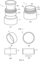
Figure 1 is a schematic representation of an example hybrid jar according to the invention; -
Figure 2 comprises various views of an outer part of the example hybrid jar ofFigure 1 ; -
Figure 3 comprises various views of a second plastic part of the example hybrid jar ofFigure 1 ; -
Figure 4 comprises various views of a first plastic part of the example hybrid jar ofFigure 1 ; -
Figure 5 is a side view of an example refill capsule for the example hybrid jar ofFigure 1 ; and -
Figure 6 is a schematic representation of a further example hybrid jar not according - The present invention will now be more particularly described, by way of example, with reference to the accompanying drawings.
- Example embodiments are shown and described in sufficient detail to enable those of ordinary skill in the art to embody and implement the systems and processes herein described. It is important to understand that embodiments can be provided in many alternate forms and should not be construed as limited to the examples set forth herein, as long as these fall within the scope of the invention as defined by the appended claims.
- Accordingly, while embodiments can be modified in various ways and take on various alternative forms, specific embodiments thereof are shown in the drawings and described in detail below as examples. There is no intent to limit to the particular forms disclosed. On the contrary, all modifications, equivalents, and alternatives falling within the scope of the appended claims should be included. Elements of the example embodiments are consistently denoted by the same reference numerals throughout the drawings and detailed description where 15 appropriate.
- The invention is not limited in the design and shape of the structure shown in the drawings.
- The terminology used herein to describe embodiments is not intended to limit the scope. The articles "a," "an," and "the" are singular in that they have a single referent, however the use of the singular form in the present document should not preclude the presence of more than one referent. In other words, elements referred to in the singular can number one or more, unless the context clearly indicates otherwise. It will be further understood that the terms "comprises," "comprising," "includes," and/or "including," when used herein, specify the presence of stated features, items, steps, operations, elements, and/or components, but do not preclude the presence or addition of one or more other features, items, steps, operations, elements, components, and/or groups thereof.
- Unless otherwise defined, all terms (including technical and scientific terms) used herein are to be interpreted as is customary in the art. It will be further understood that terms in common usage should also be interpreted as is customary in the relevant art and not in an idealized or overly formal sense unless expressly so defined herein.
- In the following description, all orientational terms, such as upper, lower, radially and axially, are used in relation to the drawings and should not be interpreted as limiting on the invention.
- Each example container according to the present invention comprises a rigid fibrous outer part and a rigid plastic inner part. In each example the inner part is configured to contain a product, and is removably attached to the outer part such that at least a portion of the inner part is disposed inside the outer part. The term "rigid" is intended to mean self-supporting, such that a rigid part is able to maintain a desired shape and configuration without support from any other object.
- The term "removably" is intended to mean that the attached parts can be separated by a user without damaging either of the parts, and without the use of any tools.
- A container formed in accordance with the present invention may, for example, be a cup, pot, tub or a jar. Such a container may be configured to contain a liquid or semi-liquid product such as a cream, paste or gel. Such a container may be configured to contain a powder. The product may be a cosmetics product. In some examples the product may be a food product.
- Hybrid containers according to the invention enable advantageously enable a significant reduction in the amount of plastic comprised in the container compared to a thick-walled plastic jar, because the thickness of the wall is mainly provided by the fibrous part. A further advantage is that, because the fibre part is easily and cleanly separable from the plastic part(s), recycling of each part is facilitated. Hybrid containers according to the invention may exclusively comprise recyclable materials.
- Different aspects and embodiments of the invention may be used separately or together.
-
Figure 1 shows a firstexample hybrid container 1 according to the invention. Thehybrid container 1 comprises a rigid fibrousouter part 11 and a rigid plasticinner part outer part 11 such that at least a portion of theinner part outer part 11. - The
inner part opening 129 through which the inside of thecontainer 1 is able to be accessed. In the particular example ofFigure 1 , thecontainer 1 is substantially cylindrical and theopening 129 is circular, with a diameter at least 60% of the outer diameter of thecontainer 1. The diameter of theopening 129 may be at least 75% of the outer diameter of the container. Thecontainer 1 is therefore a "wide-mouth" container. In other examples the diameter of theopening 129 may be less than 60% of the outer diameter of thecontainer 1. - In this example the
hybrid container 1 is refillable. To enable refilling of thehybrid container 1, theinner part plastic part 12a removably connected to a rigid secondplastic part 12b. The manner in which the two-part construction of theinner part container 1 will become clear from the following discussion. - Part (i) of
Figure 1 is an exploded view of thecontainer 1 which shows theouter part 11, the firstplastic part 12a, and the secondplastic part 12b separately, and part (ii) is a perspective view of thecontainer 1 in an intended in-use state. -
Figure 2 shows theouter part 11 in isolation. Part (i) is a perspective view of theouter part 11, part (ii) is an end view; part (iii) is a side view; and part (iv) is a cross-section taken along the line A-A. - The fibrous
outer part 11 is cylindrical. At least in this example, the fibrousouter part 11 does not comprise a base, meaning that at least the firstplastic part 12a of the plasticinner part container 1. The cylindrical wall of theouter part 11 may be relatively thick, in order to provide a desired level of rigidity and to emulate the visual appearance and configuration of a thick-walled plastic or glass container. - The fibrous
outer part 11 is formed exclusively from a single fibrous material. - The fibrous
outer part 11 is formed from cardboard. In other other examples, not being part of the invention, the fibrous outer part may be formed from, for example, paperboard, or fibreboard. - In some examples the fibrous
outer part 11 is formed from a recycled fibrous material. Theouter part 11 may be formed as a continuous cylindrical portion of material with no seams (as opposed to, for example, a rectangular portion with joined ends). Theouter part 11 may be formed by slicing a tube of fibrous material. Such tubes are well-known and widely available, meaning that the fibrousouter part 11 may be very simple and inexpensive to manufacture. Furthermore, this method of manufacturing the fibrousouter part 11 means that the fibrousouter part 11 can be exclusively formed from a single fibrous material, since no bonding agents or the like are required to be used. - The first
plastic part 12a is shown in isolation inFigure 3 , in which part (i) is a side view and part (ii) is a view from below. The firstplastic part 12a is configured to contain a product, which may be any of the types of product listed above. In this particular example, the firstplastic part 12a is configured to contain a cosmetics cream. The firstplastic part 12a has acircumferential sidewall 122 that extends upwardly from the edge of acircular base 123. The firstplastic part 12a defines theopening 129 and bounds a cavity for containing the product. - The first
plastic part 12a is unitary and is formed exclusively from a single plastics material. The firstplastic part 12a may be formed by injection moulding. The firstplastic part 12a may be formed by thermoforming. - The first
plastic part 12a may, in some examples, be formed from a food approved plastics material. This will be the case where thecontainer 2 is intended to contain a cosmetic or food product, since the firstplastic part 12a directly contacts a product contained by thecontainer 2. The firstplastic part 12a may be formed from a recycled plastics material. The firstplastic part 12a may be formed from a blend of a recycled plastics material and a non-recycled plastics material. Such a blend may preferably contain at least 30% recycled plastics material. Such a blend may contain at least 50% recycled plastics material. The firstplastic part 12a may be formed from PET, rPET, or a blend of PET and rPET. The firstplastic part 12a may be formed from a polyolefin polymer such as polypropylene (PP). In the particular example, the firstplastic part 12a is formed from recycled PP (rPP) or from a blend of rPP and PP. Other plastics materials which may be used to form the firstplastic part 12a include nylon, polystyrene, TPE (Thermoplastic Elastomer), TPS (Thermoplastic Starch). - From
Figure 2 it can be seen that, in this particular example, thebase 123 is concave (with respect to the interior of the container 1), and that the circumferential region of the firstplastic part 12a where thebase 123 joins thesidewall 122 is curved. Theconcave base 123 and curved joining region avoids sharp corners from which it is difficult for a user to remove a product contained by thecontainer 1. - It can also be seen that the first
plastic part 12a comprises arim 124. Therim 124 defines a downward-facing U-shaped circumferential recess. An upper circumferential edge of the secondplastic part 12b is received in the recess. Therim 124 therefore provides a mechanical connection between the first and secondplastic parts rim 124 prevents the firstplastic part 12a from moving downwardly relative to the secondplastic part 12b, whilst permitting the firstplastic part 12a to move upwardly relative to the secondplastic part 12b. Therim 124 thereby enables the firstplastic part 12a to be retained on the secondplastic part 12b in a desired position relative to the secondplastic part 12b by gravity, in an in-use orientation of thecontainer 2. - In some examples the circumference of the
rim 124 may be sized relative to the circumference of the secondplastic part 12b such that there is an interference fit therebetween. In some examples therim 124 may comprise one or more retention features, such as one or more inwardly extending protrusions, configured to engage with one or more corresponding retention features (such as one or more outwardly extending protrusions) on the secondplastic part 12b. Such retention features may create a snap-connection between the first and secondplastic parts plastic parts plastic parts plastic parts - The second
plastic part 12b has the form of a ring, which surrounds the side wall of the firstplastic part 12a such that the firstplastic part 12a is disposed substantially within the secondplastic part 12b. The secondplastic part 12b is unitary and is formed exclusively from a single plastics material. The secondplastic part 12b may be formed from a different plastics material to the firstplastic part 12a. The secondplastic part 12b may be formed by injection moulding. The secondplastic part 12b may be formed by thermoforming. - The second
plastic part 12b does not contact a product contained by thecontainer 2, so there is no need for the secondplastic part 12b to be formed from a food approved plastics material. The secondplastic part 12b may be formed from a recycled plastics material. The secondplastic part 12b may be formed from a blend of a recycled plastics material and a non-recycled plastics material. Such a blend may preferably contain at least 30% recycled plastics material. Such a blend may contain at least 50% recycled plastics material. The secondplastic part 12b may be formed from PP, rPP, or a blend of PP and rPP. In the particular example, the secondplastic part 12b is formed from rPET or from a blend of rPET and PET. Other plastics materials which may be used to form the firstplastic part 12a include nylon, polystyrene, TPE, TPS. - The second
plastic part 12b is configured to removably engage with a lid (not illustrated). In the illustrated example, ascrew thread 121 is provided on an upper outer surface of the secondplastic part 12b, thescrew thread 121 being configured to engage with a corresponding screw thread on an inner surface of a lid. Thescrew thread 121 is provided on a portion of the secondplastic part 12b which is not disposed within theouter part 11. In other examples, the secondplastic part 12b may be configured to removably engage with a lid via a different mechanism, such as a snap-fit mechanism or bayonet mechanism. It is advantageous for the secondplastic part 12b to be configured to engage with a lid, because this means that theouter part 11 does not need to engage with the lid. Theouter part 11 may therefore have a very simple construction, which makes it possible to form theouter part 11 from a highly recyclable and inexpensive fibrous material, as described above. -
Figure 4 shows the secondplastic part 12b in isolation. Part (i) is a side view; part (ii) is a view from below; part (iii) is a cross-section; part (iv) is a perspective view; and part (v) is an enlarged view of the region A of part (iv). - The second
plastic part 12b is removably attached to theouter part 11 such that a lower (with respect to an intended in-use orientation of the container 1) portion of the secondplastic part 12b is disposed inside theouter part 11. The removable attachment is configured such that theouter part 11 and the secondplastic part 12b will remain securely attached during normal use of thecontainer 1. The term "normal use" is intended to mean use of the container to store and dispense a product contained therein, and to exclude, for example the manufacturing and disposal stages of the lifecycle of thecontainer 1. - However; the removable attachment is configured such that when it is desired to dispose of the
container 1, theouter part 11 and the secondplastic part 12b may easily be separated by a user. Achieving the separation does not require any special tools or the application of a particularly high level of force. However; the removable attachment may be configured such that certain movements or forces not required and not likely to be applied during normal use of the container are required in order to separate theouter part 11 from the secondplastic part 12b. - The attachment between the second
plastic part 12b and theouter part 11 is configured to prevent relative movement, in any direction, between the secondplastic part 12b and theouter part 11 during normal use of thecontainer 1. - The attachment between the second
plastic part 12b and theouter part 11 is in the form of a mechanical connection, meaning that no bonding agent (such as glue) is used to form the attachment. For example, the secondplastic part 12b may be attached to theouter part 11 by a push-fit connection. In the particular illustrated example the secondplastic part 12b is connected to theouter part 11 by an interference-fit connection, which is achieved through selecting an appropriate inner diameter of a region of theouter part 11 and an appropriate outer diameter of a corresponding region of the secondplastic part 12b. These diameters should be selected to create a desired degree of resistance to relative movement of theouter part 11 and the secondplastic part 12b. In particular, the degree of resistance should be high enough to ensure that relative movement does not take place during normal use of thecontainer 1, but low enough that the vast majority of users are able to separate theouter part 11 and the secondplastic part 12b without undue difficulty when they wish to dispose of thecontainer 1. - The second
plastic part 12b may comprise at least one first engagement feature on an outer surface of the secondplastic part 12b. Such a first engagement feature may, for example, take the form of a circumferential protrusion (not illustrated) configured to facilitate achieving an interference fit with theouter part 11. Such a circumferential protrusion would be provided on a portion of the secondplastic part 12b that is disposed within theouter part 11. Such a circumferential protrusion may be sized such that it presses into the fibrous material of theouter part 11, to better resist relative axial movement of theouter part 11 and the secondplastic part 12b. - In some examples such a circumferential protrusion may be resilient, and sized such that it becomes deformed during a process of attaching the inner and
outer parts 12, 11. In such examples the degree of resistance to relative movement of theouter part 11 and secondplastic part 12b provided by the interference-fit connection will partially depend on the resilience of the circumferential protrusion (a less resilient protrusion will create a stronger resistance to relative movement, and vice versa). The resilience should therefore be selected, in combination with the diameters described above, to create a desired degree of resistance to relative movement. - In some examples, the at least one first engagement feature may comprise one or more anti-rotation features configured to prevent relative circumferential movement therebetween during normal use. In particular, such anti-rotation features may be configured to prevent relative circumferential movement between the second
plastic part 12b and theouter part 11 during the actions of removing and replacing a screw-on lid. - It can be seen from
Figure 4 that the secondplastic part 12b comprises anti-rotation features in the form of multipleaxially extending ribs 126, which protrude from the outer circumferential surface of the portion of the secondplastic part 12b which is disposed inside theouter part 11. Theribs 126 are distributed around the circumference of the secondplastic part 12b. Theribs 126 operate to prevent relative circumferential movement between the secondplastic part 12b and theouter part 11 during normal use of thecontainer 1. - It can also be seen from
Figure 4 that the secondplastic part 12b comprises an outwardly extendingcircumferential protrusion 125. The outer circumference of thisprotrusion 125 is greater than the inner circumference of theouter part 11. Theprotrusion 125 sits against and covers an upper edge of theouter part 11. - The
protrusion 125 thereby protects the upper edge of theouter part 11 and also sets the axial position of the secondplastic part 12b relative to theouter part 11. - The second
plastic part 12b further comprises at least one second engagement feature configured to mechanically engage with the firstplastic part 12a so as to resist relative movement of the first and secondplastic parts plastic part 12b mechanically engages with therim 124 of the firstplastic part 12a, and therefore functions as such a second engagement feature. As explained above, the engagement of the upper circumferential edge of the secondplastic part 12b with therim 124 of the firstplastic part 12a prevents the firstplastic part 12a from moving downwardly (with respect to an in-use orientation of the container 1) relative to the secondplastic part 12b. - In other examples second engagement features may comprise any features configured to resist relative movement of the first and second
plastic parts plastic part 12a in order to resist upward movement of the firstplastic part 12a relative to the secondplastic part 12b. In such examples the second engagement features may be configured to only resist upward movement of the firstplastic part 12a against a relatively low degree of force, such as that experienced when thecontainer 1 is inverted relative to the in-use orientation. The second engagement features may be configured to permit upward movement of the firstplastic part 12a when a relatively higher degree of force is applied to drive the upward movement, such as a force that may easily be applied by a user wishing to remove the firstplastic part 12a from thecontainer 1. - The
example hybrid container 1 is refillable. Thecontainer 1 is configured to be refilled by replacing an empty firstplastic part 12a with a full firstplastic part 12a. The empty firstplastic part 12a may then be recycled. The removable connection between the firstplastic part 12a and the secondplastic part 12b enables the user to easily remove the empty firstplastic part 12a from the container and then insert a different, full, firstplastic part 12a. The secondplastic part 12b and theouter part 11 may be retained by the user and refilled in this manner multiple times (for example until the condition of theouter part 11 and/or the secondplastic part 12b degrades enough to warrant replacement of the entire container 1). -
Figure 5 is a side view of anexample refill capsule 5 suitable for use with thehybrid container 1. Therefill capsule 5 is configured to form part of thehybrid container 1. Thecapsule 5 comprises a first rigidplastic part 12a which is identical to the first rigidplastic part 12a described above. Aremovable closure 51 of any suitable type is disposed on the first rigidplastic part 12a such that the first rigidplastic part 12a and theremovable closure 51 together define a sealed space. A product is contained within the sealed space. Theremovable closure 51 may, for example, comprise a film or membrane attached to the upper circumferential edge of the firstplastic part 12a by any suitable attachment mechanism. -
Figure 6 shows a secondexample hybrid container 2 not according to the invention. - The
hybrid container 2 comprises a rigid fibrousouter part 11 and a rigid plasticinner part 22. Features of the secondexample hybrid container 2 which are substantially identical to equivalent features of the firstexample hybrid container 1 have been denoted using the same reference numbers and will not be further discussed. In particular, theouter part 11 of the secondexample hybrid container 2 is substantially identical to theouter part 11 of the firstexample hybrid container 1. Unlike the firstexample hybrid container 1, thehybrid container 2 is not intended to be refillable by a consumer. Instead it has a construction which enables it to be formed from just two different recyclable materials, which are easily separated by the consumer. The secondexample hybrid container 2 may therefore be completely and easily recycled. - Part (i) is an exploded view of the
container 2 which shows the inner andouter parts container 2 in an intended in-use state. - The
inner part 22 is configured to contain a product, which may be any of the types of product listed above. Theinner part 22 defines anopening 129 through which the inside of thecontainer 2 is able to be accessed. Like thecontainer 1, thecontainer 2 is a wide mouth container, and theopening 129 has a diameter at least 60% of the outer diameter of thecontainer 2. - In this example the plastic
inner part 22 is unitary and is formed exclusively from a single plastics material. The plasticinner part 22 has a circumferential sidewall, which extends upwardly from the edge of a circular base. The plasticinner part 22 directly contacts a product contained in thecontainer 2. The plasticinner part 22 may be formed in substantially the same manner as the firstplastic part 12a or in substantially the same manner as the secondplastic part 12b of the firstexample hybrid container 1. The plasticinner part 22 may be formed from any of the materials described above as being suitable for forming the firstplastic part 12a or any of the materials described above as being suitable for forming the secondplastic part 12b. In examples in which thecontainer 2 is intended to contain a cosmetic or food product, the plasticinner part 22 is formed from a food approved plastics material. In the particular example, the plasticinner part 22 is formed from rPET or from a blend of PET and rPET. - Similar to the second
plastic part 12b of theexample container 1, theinner part 22 is configured to removably engage with a lid by means of ascrew thread 121. Thescrew thread 121 is provided on an upper outer surface of theinner part 22, configured to engage with a corresponding screw thread on an inner surface of a lid. Thescrew thread 121 is provided on a portion of theinner part 22 which is not disposed within theouter part 11. - The
inner part 22 is removably attached to theouter part 11 such that a lower (with respect to an intended in-use orientation of the container 1) portion of theinner part 22 is disposed inside theouter part 11. That is, the lower portion of theinner part 22 is disposed within the space defined by the inner circumferential wall of theouter part 11. The attachment between theinner part 22 and theouter part 11 is substantially the same as the attachment between the secondplastic part 12b and theouter part 11 of the firstexample hybrid container 1.
Claims (15)
- A hybrid container (1) comprising a rigid fibrous outer part (11) and a rigid plasticinner part (12a, 12b); the inner part (12a, 12b) being configured to contain a product; wherein theinner part (12a, 12b) is removably attached to the outer part (11) such that at least a portion ofthe inner part (12a, 12b) is disposed inside the outer part (11), wherein the inner part (12a, 12b) comprisesa rigid first plastic part (12a) removably connected to a rigid second plastic part (12b), thefirst plastic part (12a) being disposed substantially within the second plastic part (12b) andbeing configured to contain the product; and the second plastic part (12b) beingremovably connected to the fibrous outer part (11), and wherein the fibrous outerpart is made of cardboard.
- A hybrid container according to claim 1, wherein the outer part (11) is exclusively formed from a single fibrous material.
- A hybrid container according to claim 1 or claim 2, wherein the inner part (12a, 12b) is exclusively formed from a single plastics material.
- A hybrid container according to claim 1 or claim 2, wherein the first plastic part (12a) is formed from a first plastics material and the second plastic part (12b) is formed from a second, different, plastics material.
- A hybrid container according to claim 4, wherein the first plastic part (12a) isexclusively formed from the first plastics material and the second part (12b) isexclusively formed from the second plastics material.
- A hybrid container according to claim 4 or claim 5, wherein the first plastics material is a food approved plastics material.
- A hybrid container according to any preceding claim, wherein the container (1) exclusively comprises recyclable materials.
- A hybrid container according to any preceding claim, wherein the inner part (12a, 12b) comprises a plastics material composed of at least 30% recycled plastics material.
- A hybrid container according to any preceding claim, wherein the outer part (11) comprises a recycled fibrous material.
- A hybrid container according to any preceding claim, wherein the inner part (12a, 12b) is removably connected to the outer part (11) by a mechanical connection.
- A hybrid container according to any preceding claim, wherein the inner part (12a, 12b) is removably connected to the outer part (11) by an interference fit.
- A hybrid container according to any preceding claim, wherein the inner part (12a, 12b) comprises anti-rotation features configured to prevent circumferential movement of the outer part (11) relative to the inner part.
- A hybrid container according to any preceding claim, wherein the inner part (12a, 12b) is configured to removably engage with a lid.
- A hybrid container according to any preceding claim, wherein the inner part (12a, 12b) defines an opening through which the inside of the container (1) is able to be accessed.
- A hybrid container according to claim 14, wherein the container is substantially cylindrical and the opening is circular, and wherein the diameter of the opening is at least 60% of the outer diameter of the container.
Applications Claiming Priority (2)
| Application Number | Priority Date | Filing Date | Title |
|---|---|---|---|
| GBGB2015817.6A GB202015817D0 (en) | 2020-10-06 | 2020-10-06 | Container |
| PCT/EP2021/074051 WO2022073698A1 (en) | 2020-10-06 | 2021-08-31 | Container |
Publications (2)
| Publication Number | Publication Date |
|---|---|
| EP4208062A1 EP4208062A1 (en) | 2023-07-12 |
| EP4208062B1 true EP4208062B1 (en) | 2025-03-05 |
Family
ID=73223667
Family Applications (1)
| Application Number | Title | Priority Date | Filing Date |
|---|---|---|---|
| EP21773003.5A Active EP4208062B1 (en) | 2020-10-06 | 2021-08-31 | Container |
Country Status (3)
| Country | Link |
|---|---|
| EP (1) | EP4208062B1 (en) |
| GB (1) | GB202015817D0 (en) |
| WO (1) | WO2022073698A1 (en) |
Family Cites Families (4)
| Publication number | Priority date | Publication date | Assignee | Title |
|---|---|---|---|---|
| US2413726A (en) * | 1944-10-23 | 1947-01-07 | F N Burt Company Inc | Cold cream jar |
| US2866569A (en) * | 1954-09-24 | 1958-12-30 | F N Burt Company Inc | Cold cream jars |
| FR3071388B1 (en) * | 2017-09-25 | 2021-07-23 | Lvmh Rech | RECHARGEABLE PACKAGING DEVICE FOR A COSMETIC PRODUCT |
| KR102085110B1 (en) * | 2019-05-01 | 2020-03-05 | (주)연우 | Cosmetic container |
-
2020
- 2020-10-06 GB GBGB2015817.6A patent/GB202015817D0/en not_active Ceased
-
2021
- 2021-08-31 WO PCT/EP2021/074051 patent/WO2022073698A1/en not_active Ceased
- 2021-08-31 EP EP21773003.5A patent/EP4208062B1/en active Active
Also Published As
| Publication number | Publication date |
|---|---|
| WO2022073698A1 (en) | 2022-04-14 |
| EP4208062A1 (en) | 2023-07-12 |
| GB202015817D0 (en) | 2020-11-18 |
Similar Documents
| Publication | Publication Date | Title |
|---|---|---|
| US12075900B2 (en) | Container with internal glass receptacle and method for assembling the container by using a spacing and locking insert | |
| EP3619134B1 (en) | Packaging kit and refill container | |
| US6006937A (en) | Container having a body, cap, and intermediary part | |
| WO2008018908A1 (en) | Plastic container | |
| US11987432B2 (en) | Device for containing a liquid or semi-liquid cosmetic or pharmaceutical product | |
| CN116888055A (en) | Containers and systems for reducing packaging waste | |
| CN115844132B (en) | Cosmetic product dispensing bottle with stacked base, refill and cap | |
| CN116098370A (en) | Refillable case for powder cosmetics | |
| EP3453635A1 (en) | Collapsable receptacle and mould for its manufacturing | |
| JP2003040304A (en) | Changeable vessel | |
| US6279780B1 (en) | Packaging for pasty liquid product with improved degree of emptying | |
| US20040040965A1 (en) | Containment vessel | |
| WO2022073698A1 (en) | Container | |
| WO1994015846A1 (en) | Single fold container with additive compartment | |
| RU2467937C2 (en) | Packing container, primarily, can-type container | |
| US20150238988A1 (en) | Fitment for polymeric bag within fiber shell container | |
| US20080210699A1 (en) | Container Applied In Medical Drugs And Cosmetic Items Packaging | |
| US11530125B2 (en) | Container | |
| JP7598275B2 (en) | Containers and dispensed products | |
| US12077356B2 (en) | Dispensing system | |
| US12329300B2 (en) | Recyclable or reusable straw in container lid assembly | |
| JP7735037B2 (en) | Synthetic resin container, preform, and method for manufacturing synthetic resin container | |
| JP2023150603A (en) | Refill container and double container containing it | |
| WO2025142512A1 (en) | Double container, refill container, and method for manufacturing refill container | |
| WO2024070926A1 (en) | Refill container and replacement container |
Legal Events
| Date | Code | Title | Description |
|---|---|---|---|
| STAA | Information on the status of an ep patent application or granted ep patent |
Free format text: STATUS: UNKNOWN |
|
| STAA | Information on the status of an ep patent application or granted ep patent |
Free format text: STATUS: THE INTERNATIONAL PUBLICATION HAS BEEN MADE |
|
| PUAI | Public reference made under article 153(3) epc to a published international application that has entered the european phase |
Free format text: ORIGINAL CODE: 0009012 |
|
| STAA | Information on the status of an ep patent application or granted ep patent |
Free format text: STATUS: REQUEST FOR EXAMINATION WAS MADE |
|
| 17P | Request for examination filed |
Effective date: 20230403 |
|
| AK | Designated contracting states |
Kind code of ref document: A1 Designated state(s): AL AT BE BG CH CY CZ DE DK EE ES FI FR GB GR HR HU IE IS IT LI LT LU LV MC MK MT NL NO PL PT RO RS SE SI SK SM TR |
|
| P01 | Opt-out of the competence of the unified patent court (upc) registered |
Effective date: 20230803 |
|
| DAV | Request for validation of the european patent (deleted) | ||
| DAX | Request for extension of the european patent (deleted) | ||
| GRAP | Despatch of communication of intention to grant a patent |
Free format text: ORIGINAL CODE: EPIDOSNIGR1 |
|
| STAA | Information on the status of an ep patent application or granted ep patent |
Free format text: STATUS: GRANT OF PATENT IS INTENDED |
|
| INTG | Intention to grant announced |
Effective date: 20241115 |
|
| GRAS | Grant fee paid |
Free format text: ORIGINAL CODE: EPIDOSNIGR3 |
|
| GRAA | (expected) grant |
Free format text: ORIGINAL CODE: 0009210 |
|
| STAA | Information on the status of an ep patent application or granted ep patent |
Free format text: STATUS: THE PATENT HAS BEEN GRANTED |
|
| AK | Designated contracting states |
Kind code of ref document: B1 Designated state(s): AL AT BE BG CH CY CZ DE DK EE ES FI FR GB GR HR HU IE IS IT LI LT LU LV MC MK MT NL NO PL PT RO RS SE SI SK SM TR |
|
| REG | Reference to a national code |
Ref country code: GB Ref legal event code: FG4D |
|
| REG | Reference to a national code |
Ref country code: CH Ref legal event code: EP |
|
| REG | Reference to a national code |
Ref country code: IE Ref legal event code: FG4D |
|
| REG | Reference to a national code |
Ref country code: DE Ref legal event code: R096 Ref document number: 602021027218 Country of ref document: DE |
|
| PG25 | Lapsed in a contracting state [announced via postgrant information from national office to epo] |
Ref country code: RS Free format text: LAPSE BECAUSE OF FAILURE TO SUBMIT A TRANSLATION OF THE DESCRIPTION OR TO PAY THE FEE WITHIN THE PRESCRIBED TIME-LIMIT Effective date: 20250605 |
|
| PG25 | Lapsed in a contracting state [announced via postgrant information from national office to epo] |
Ref country code: FI Free format text: LAPSE BECAUSE OF FAILURE TO SUBMIT A TRANSLATION OF THE DESCRIPTION OR TO PAY THE FEE WITHIN THE PRESCRIBED TIME-LIMIT Effective date: 20250305 |
|
| REG | Reference to a national code |
Ref country code: NL Ref legal event code: MP Effective date: 20250305 |
|
| PG25 | Lapsed in a contracting state [announced via postgrant information from national office to epo] |
Ref country code: ES Free format text: LAPSE BECAUSE OF FAILURE TO SUBMIT A TRANSLATION OF THE DESCRIPTION OR TO PAY THE FEE WITHIN THE PRESCRIBED TIME-LIMIT Effective date: 20250305 |
|
| REG | Reference to a national code |
Ref country code: LT Ref legal event code: MG9D |
|
| PG25 | Lapsed in a contracting state [announced via postgrant information from national office to epo] |
Ref country code: NO Free format text: LAPSE BECAUSE OF FAILURE TO SUBMIT A TRANSLATION OF THE DESCRIPTION OR TO PAY THE FEE WITHIN THE PRESCRIBED TIME-LIMIT Effective date: 20250605 |
|
| PG25 | Lapsed in a contracting state [announced via postgrant information from national office to epo] |
Ref country code: HR Free format text: LAPSE BECAUSE OF FAILURE TO SUBMIT A TRANSLATION OF THE DESCRIPTION OR TO PAY THE FEE WITHIN THE PRESCRIBED TIME-LIMIT Effective date: 20250305 |
|
| PG25 | Lapsed in a contracting state [announced via postgrant information from national office to epo] |
Ref country code: LV Free format text: LAPSE BECAUSE OF FAILURE TO SUBMIT A TRANSLATION OF THE DESCRIPTION OR TO PAY THE FEE WITHIN THE PRESCRIBED TIME-LIMIT Effective date: 20250305 |
|
| PG25 | Lapsed in a contracting state [announced via postgrant information from national office to epo] |
Ref country code: GR Free format text: LAPSE BECAUSE OF FAILURE TO SUBMIT A TRANSLATION OF THE DESCRIPTION OR TO PAY THE FEE WITHIN THE PRESCRIBED TIME-LIMIT Effective date: 20250606 Ref country code: BG Free format text: LAPSE BECAUSE OF FAILURE TO SUBMIT A TRANSLATION OF THE DESCRIPTION OR TO PAY THE FEE WITHIN THE PRESCRIBED TIME-LIMIT Effective date: 20250305 |
|
| REG | Reference to a national code |
Ref country code: AT Ref legal event code: MK05 Ref document number: 1772060 Country of ref document: AT Kind code of ref document: T Effective date: 20250305 |
|
| PG25 | Lapsed in a contracting state [announced via postgrant information from national office to epo] |
Ref country code: NL Free format text: LAPSE BECAUSE OF FAILURE TO SUBMIT A TRANSLATION OF THE DESCRIPTION OR TO PAY THE FEE WITHIN THE PRESCRIBED TIME-LIMIT Effective date: 20250305 |
|
| PG25 | Lapsed in a contracting state [announced via postgrant information from national office to epo] |
Ref country code: SE Free format text: LAPSE BECAUSE OF FAILURE TO SUBMIT A TRANSLATION OF THE DESCRIPTION OR TO PAY THE FEE WITHIN THE PRESCRIBED TIME-LIMIT Effective date: 20250305 |
|
| PG25 | Lapsed in a contracting state [announced via postgrant information from national office to epo] |
Ref country code: SM Free format text: LAPSE BECAUSE OF FAILURE TO SUBMIT A TRANSLATION OF THE DESCRIPTION OR TO PAY THE FEE WITHIN THE PRESCRIBED TIME-LIMIT Effective date: 20250305 |
|
| PG25 | Lapsed in a contracting state [announced via postgrant information from national office to epo] |
Ref country code: PT Free format text: LAPSE BECAUSE OF FAILURE TO SUBMIT A TRANSLATION OF THE DESCRIPTION OR TO PAY THE FEE WITHIN THE PRESCRIBED TIME-LIMIT Effective date: 20250707 |
|
| PGFP | Annual fee paid to national office [announced via postgrant information from national office to epo] |
Ref country code: DE Payment date: 20250827 Year of fee payment: 5 |
|
| PG25 | Lapsed in a contracting state [announced via postgrant information from national office to epo] |
Ref country code: IT Free format text: LAPSE BECAUSE OF FAILURE TO SUBMIT A TRANSLATION OF THE DESCRIPTION OR TO PAY THE FEE WITHIN THE PRESCRIBED TIME-LIMIT Effective date: 20250305 Ref country code: PL Free format text: LAPSE BECAUSE OF FAILURE TO SUBMIT A TRANSLATION OF THE DESCRIPTION OR TO PAY THE FEE WITHIN THE PRESCRIBED TIME-LIMIT Effective date: 20250305 |
|
| PGFP | Annual fee paid to national office [announced via postgrant information from national office to epo] |
Ref country code: GB Payment date: 20250826 Year of fee payment: 5 |
|
| PG25 | Lapsed in a contracting state [announced via postgrant information from national office to epo] |
Ref country code: AT Free format text: LAPSE BECAUSE OF FAILURE TO SUBMIT A TRANSLATION OF THE DESCRIPTION OR TO PAY THE FEE WITHIN THE PRESCRIBED TIME-LIMIT Effective date: 20250305 |
|
| PGFP | Annual fee paid to national office [announced via postgrant information from national office to epo] |
Ref country code: FR Payment date: 20250825 Year of fee payment: 5 |
|
| PG25 | Lapsed in a contracting state [announced via postgrant information from national office to epo] |
Ref country code: CZ Free format text: LAPSE BECAUSE OF FAILURE TO SUBMIT A TRANSLATION OF THE DESCRIPTION OR TO PAY THE FEE WITHIN THE PRESCRIBED TIME-LIMIT Effective date: 20250305 Ref country code: EE Free format text: LAPSE BECAUSE OF FAILURE TO SUBMIT A TRANSLATION OF THE DESCRIPTION OR TO PAY THE FEE WITHIN THE PRESCRIBED TIME-LIMIT Effective date: 20250305 |
|
| PG25 | Lapsed in a contracting state [announced via postgrant information from national office to epo] |
Ref country code: RO Free format text: LAPSE BECAUSE OF FAILURE TO SUBMIT A TRANSLATION OF THE DESCRIPTION OR TO PAY THE FEE WITHIN THE PRESCRIBED TIME-LIMIT Effective date: 20250305 |
|
| PG25 | Lapsed in a contracting state [announced via postgrant information from national office to epo] |
Ref country code: SK Free format text: LAPSE BECAUSE OF FAILURE TO SUBMIT A TRANSLATION OF THE DESCRIPTION OR TO PAY THE FEE WITHIN THE PRESCRIBED TIME-LIMIT Effective date: 20250305 |
|
| PG25 | Lapsed in a contracting state [announced via postgrant information from national office to epo] |
Ref country code: IS Free format text: LAPSE BECAUSE OF FAILURE TO SUBMIT A TRANSLATION OF THE DESCRIPTION OR TO PAY THE FEE WITHIN THE PRESCRIBED TIME-LIMIT Effective date: 20250705 |
|
| REG | Reference to a national code |
Ref country code: DE Ref legal event code: R097 Ref document number: 602021027218 Country of ref document: DE |
|
| PLBE | No opposition filed within time limit |
Free format text: ORIGINAL CODE: 0009261 |
|
| STAA | Information on the status of an ep patent application or granted ep patent |
Free format text: STATUS: NO OPPOSITION FILED WITHIN TIME LIMIT |
|
| PG25 | Lapsed in a contracting state [announced via postgrant information from national office to epo] |
Ref country code: DK Free format text: LAPSE BECAUSE OF FAILURE TO SUBMIT A TRANSLATION OF THE DESCRIPTION OR TO PAY THE FEE WITHIN THE PRESCRIBED TIME-LIMIT Effective date: 20250305 |
|
| REG | Reference to a national code |
Ref country code: CH Ref legal event code: L10 Free format text: ST27 STATUS EVENT CODE: U-0-0-L10-L00 (AS PROVIDED BY THE NATIONAL OFFICE) Effective date: 20260114 |
|
| 26N | No opposition filed |
Effective date: 20251208 |
|
| REG | Reference to a national code |
Ref country code: CH Ref legal event code: H13 Free format text: ST27 STATUS EVENT CODE: U-0-0-H10-H13 (AS PROVIDED BY THE NATIONAL OFFICE) Effective date: 20260324 |
|
| PG25 | Lapsed in a contracting state [announced via postgrant information from national office to epo] |
Ref country code: MC Free format text: LAPSE BECAUSE OF FAILURE TO SUBMIT A TRANSLATION OF THE DESCRIPTION OR TO PAY THE FEE WITHIN THE PRESCRIBED TIME-LIMIT Effective date: 20250305 |
|
| PG25 | Lapsed in a contracting state [announced via postgrant information from national office to epo] |
Ref country code: LU Free format text: LAPSE BECAUSE OF NON-PAYMENT OF DUE FEES Effective date: 20250831 |
|
| PG25 | Lapsed in a contracting state [announced via postgrant information from national office to epo] |
Ref country code: CH Free format text: LAPSE BECAUSE OF NON-PAYMENT OF DUE FEES Effective date: 20250831 |