EP4207946A1 - Heat-generating assembly, cooking appliance and cooking device - Google Patents
Heat-generating assembly, cooking appliance and cooking device Download PDFInfo
- Publication number
- EP4207946A1 EP4207946A1 EP22209473.2A EP22209473A EP4207946A1 EP 4207946 A1 EP4207946 A1 EP 4207946A1 EP 22209473 A EP22209473 A EP 22209473A EP 4207946 A1 EP4207946 A1 EP 4207946A1
- Authority
- EP
- European Patent Office
- Prior art keywords
- heating layer
- heat
- metal plate
- generating assembly
- particle aggregates
- Prior art date
- Legal status (The legal status is an assumption and is not a legal conclusion. Google has not performed a legal analysis and makes no representation as to the accuracy of the status listed.)
- Granted
Links
Images


Classifications
-
- A—HUMAN NECESSITIES
- A47—FURNITURE; DOMESTIC ARTICLES OR APPLIANCES; COFFEE MILLS; SPICE MILLS; SUCTION CLEANERS IN GENERAL
- A47J—KITCHEN EQUIPMENT; COFFEE MILLS; SPICE MILLS; APPARATUS FOR MAKING BEVERAGES
- A47J36/00—Parts, details or accessories of cooking-vessels
- A47J36/02—Selection of specific materials, e.g. heavy bottoms with copper inlay or with insulating inlay
- A47J36/04—Selection of specific materials, e.g. heavy bottoms with copper inlay or with insulating inlay the materials being non-metallic
-
- H—ELECTRICITY
- H05—ELECTRIC TECHNIQUES NOT OTHERWISE PROVIDED FOR
- H05B—ELECTRIC HEATING; ELECTRIC LIGHT SOURCES NOT OTHERWISE PROVIDED FOR; CIRCUIT ARRANGEMENTS FOR ELECTRIC LIGHT SOURCES, IN GENERAL
- H05B6/00—Heating by electric, magnetic or electromagnetic fields
- H05B6/02—Induction heating
- H05B6/10—Induction heating apparatus, other than furnaces, for specific applications
- H05B6/12—Cooking devices
- H05B6/1209—Cooking devices induction cooking plates or the like and devices to be used in combination with them
-
- A—HUMAN NECESSITIES
- A47—FURNITURE; DOMESTIC ARTICLES OR APPLIANCES; COFFEE MILLS; SPICE MILLS; SUCTION CLEANERS IN GENERAL
- A47J—KITCHEN EQUIPMENT; COFFEE MILLS; SPICE MILLS; APPARATUS FOR MAKING BEVERAGES
- A47J27/00—Cooking-vessels
- A47J27/002—Construction of cooking-vessels; Methods or processes of manufacturing specially adapted for cooking-vessels
-
- A—HUMAN NECESSITIES
- A47—FURNITURE; DOMESTIC ARTICLES OR APPLIANCES; COFFEE MILLS; SPICE MILLS; SUCTION CLEANERS IN GENERAL
- A47J—KITCHEN EQUIPMENT; COFFEE MILLS; SPICE MILLS; APPARATUS FOR MAKING BEVERAGES
- A47J36/00—Parts, details or accessories of cooking-vessels
- A47J36/02—Selection of specific materials, e.g. heavy bottoms with copper inlay or with insulating inlay
-
- B—PERFORMING OPERATIONS; TRANSPORTING
- B32—LAYERED PRODUCTS
- B32B—LAYERED PRODUCTS, i.e. PRODUCTS BUILT-UP OF STRATA OF FLAT OR NON-FLAT, e.g. CELLULAR OR HONEYCOMB, FORM
- B32B17/00—Layered products essentially comprising sheet glass, or glass, slag, or like fibres
- B32B17/06—Layered products essentially comprising sheet glass, or glass, slag, or like fibres comprising glass as the main or only constituent of a layer, next to another layer of a specific material
-
- B—PERFORMING OPERATIONS; TRANSPORTING
- B32—LAYERED PRODUCTS
- B32B—LAYERED PRODUCTS, i.e. PRODUCTS BUILT-UP OF STRATA OF FLAT OR NON-FLAT, e.g. CELLULAR OR HONEYCOMB, FORM
- B32B18/00—Layered products essentially comprising ceramics, e.g. refractory products
-
- B—PERFORMING OPERATIONS; TRANSPORTING
- B32—LAYERED PRODUCTS
- B32B—LAYERED PRODUCTS, i.e. PRODUCTS BUILT-UP OF STRATA OF FLAT OR NON-FLAT, e.g. CELLULAR OR HONEYCOMB, FORM
- B32B19/00—Layered products comprising a layer of natural mineral fibres or particles, e.g. asbestos, mica
- B32B19/02—Layered products comprising a layer of natural mineral fibres or particles, e.g. asbestos, mica the layer of fibres or particles being impregnated or embedded in a plastic substance
-
- B—PERFORMING OPERATIONS; TRANSPORTING
- B32—LAYERED PRODUCTS
- B32B—LAYERED PRODUCTS, i.e. PRODUCTS BUILT-UP OF STRATA OF FLAT OR NON-FLAT, e.g. CELLULAR OR HONEYCOMB, FORM
- B32B9/00—Layered products comprising a layer of a particular substance not covered by groups B32B11/00 - B32B29/00
- B32B9/005—Layered products comprising a layer of a particular substance not covered by groups B32B11/00 - B32B29/00 comprising one layer of ceramic material, e.g. porcelain, ceramic tile
-
- H—ELECTRICITY
- H05—ELECTRIC TECHNIQUES NOT OTHERWISE PROVIDED FOR
- H05B—ELECTRIC HEATING; ELECTRIC LIGHT SOURCES NOT OTHERWISE PROVIDED FOR; CIRCUIT ARRANGEMENTS FOR ELECTRIC LIGHT SOURCES, IN GENERAL
- H05B3/00—Ohmic-resistance heating
- H05B3/10—Heating elements characterised by the composition or nature of the materials or by the arrangement of the conductor
- H05B3/18—Heating elements characterised by the composition or nature of the materials or by the arrangement of the conductor the conductor being embedded in an insulating material
-
- B—PERFORMING OPERATIONS; TRANSPORTING
- B32—LAYERED PRODUCTS
- B32B—LAYERED PRODUCTS, i.e. PRODUCTS BUILT-UP OF STRATA OF FLAT OR NON-FLAT, e.g. CELLULAR OR HONEYCOMB, FORM
- B32B2260/00—Layered product comprising an impregnated, embedded, or bonded layer wherein the layer comprises an impregnation, embedding, or binder material
- B32B2260/02—Composition of the impregnated, bonded or embedded layer
- B32B2260/025—Particulate layer
-
- B—PERFORMING OPERATIONS; TRANSPORTING
- B32—LAYERED PRODUCTS
- B32B—LAYERED PRODUCTS, i.e. PRODUCTS BUILT-UP OF STRATA OF FLAT OR NON-FLAT, e.g. CELLULAR OR HONEYCOMB, FORM
- B32B2264/00—Composition or properties of particles which form a particulate layer or are present as additives
- B32B2264/50—Particles characterised by their position or distribution in a layer
- B32B2264/503—Particles characterised by their position or distribution in a layer distributed in a predetermined pattern in a thickness direction
-
- Y—GENERAL TAGGING OF NEW TECHNOLOGICAL DEVELOPMENTS; GENERAL TAGGING OF CROSS-SECTIONAL TECHNOLOGIES SPANNING OVER SEVERAL SECTIONS OF THE IPC; TECHNICAL SUBJECTS COVERED BY FORMER USPC CROSS-REFERENCE ART COLLECTIONS [XRACs] AND DIGESTS
- Y02—TECHNOLOGIES OR APPLICATIONS FOR MITIGATION OR ADAPTATION AGAINST CLIMATE CHANGE
- Y02B—CLIMATE CHANGE MITIGATION TECHNOLOGIES RELATED TO BUILDINGS, e.g. HOUSING, HOUSE APPLIANCES OR RELATED END-USER APPLICATIONS
- Y02B30/00—Energy efficient heating, ventilation or air conditioning [HVAC]
Definitions
- the present disclosure relates to the technical field of household appliances, and more particularly, to a heat-generating assembly, a cooking appliance, and a cooking device.
- a conventional heating method mainly adopts a heat-generating assembly such as a heat-generating tube and a heat-generating plate. Glassware is brought into contact with the heat-generating tube and the heat-generating plate for heat transfer.
- the current heat-generating assembly also needs to be further improved.
- an object of the present disclosure is to provide a heat-generating assembly, a cooking appliance, and a cooking device.
- the heat-generating assembly has advantages such as high heat transfer efficiency, uniform heat transfer, and high heating stability, to remarkably improve cooking effects and service life of the cooking device and the cooking appliance including the heat-generating assembly.
- a heat-generating assembly includes two non-metal plates, a heating layer located between the non-metal plates.
- the heating layer includes an inorganic oxide matrix, and metal powder particles distributed in the inorganic oxide matrix.
- a plurality of particle aggregates is formed by the metal powder particles and arranged in a thickness direction of the heating layer. Therefore, heating efficiency, heating uniformity and heating stability of the heat-generating assembly are improved. Meanwhile, thermal stress generated during the heating is reduced, and risks of cracking and inter-layer peeling of the heating layer are reduced.
- the plurality of particle aggregates is arranged at intervals and/or adjoined to each other in the thickness direction of the heating layer. Therefore, the thermal stress generated during the heating is reduced, and absorption of the inorganic oxide matrix for the thermal stress is facilitated. Thus, stability of resistance of the heat-generating assembly is improved, and appearance effect of the heat-generating assembly is improved.
- the plurality of particle aggregates is arranged at intervals in an extending direction of the non-metal plates.
- the non-metal plates are uniformly heated.
- the plurality of particle aggregates is staggered with each other in the thickness direction of the heating layer. Therefore, the non-metal plates are uniformly heated, and a risk of a fracture of the non-metal plates is reduced.
- the particle aggregates are connected to each other by the inorganic oxide matrix, and the inorganic oxide matrix has pores. Therefore, the thermal stress generated during the heating is reduced, and risks of the cracking and the peeling of the heating layer are reduced.
- a pore is formed at a connection of the particle aggregate and the inorganic oxide matrix.
- the pores in the inorganic oxide matrix each have a smaller size than the pore at the connection between the particle aggregate and the inorganic oxide matrix. Therefore, the size of each pore in the inorganic oxide matrix is small, which can improve stability of the inorganic oxide matrix structure, and reduce the risk of inter-layer peeling of the heating layer.
- the plurality of particle aggregates is arranged in a same direction along the extending direction of the non-metal plates.
- the non-metal plates are uniformly heated.
- the plurality of particle aggregates is arranged parallel to the non-metal plates. Therefore, the non-metal plates are uniformly heated, and the risk of fracture of the non-metal plates is reduced.
- the particle aggregate is of an irregular shape.
- the particle aggregate has a long axis extending in an extending direction of the non-metal plates, and a short axis extending in the thickness direction of the heating layer. Therefore, the heating efficiency is improved, heat transfer is uniform, and risk of cracking and peeling of the heating layer is reduced.
- the plurality of particle aggregates is arranged in layers in the thickness direction of the heating layer.
- the particle aggregates in each of the layers are arranged at intervals and/or adjoined to each other in an extending direction of the non-metal plates. Therefore, the heating efficiency is improved, heat transfer is uniform, and risk of cracking and peeling of the heating layer is reduced.
- two adjacent layers of particle aggregates are connected by the inorganic oxide matrix. Therefore, uniformity of heat transfer is improved, and aggregation of heat in the heating layer is reduced.
- the plurality of particle aggregates is arranged away from the non-metal plates, and spaced apart from the non-metal plates by the inorganic oxide matrix. Therefore, the uniformity of heat transfer is improved, the non-metal plates are prevented from being broken, and noise during the heating is reduced to a certain extent.
- the plurality of particle aggregates in the heating layer is arranged away from a middle region of the heating layer. Therefore, it is avoided that the heat is aggregated in a middle part of the heating layer to cause the heating layer to peeling, and bubbles generated in the heat-generating assembly are avoided to a certain extent.
- the heating layer is embedded into the non-metal plate.
- a contact interface between the heating layer and the non-metal plate is a concave-convex interface.
- uniformity of heat transfer to the non-metal plate is improved.
- the non-metal plates are different in thickness.
- a heat-generating assembly includes two non-metal plates, and a heating layer located between the non-metal plates.
- the heating layer includes metal powder particles and an inorganic oxide matrix.
- the metal powder particles are distributed in the inorganic oxide matrix.
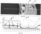
- a content of the metal powder particles follows a changing trend of increasing, then decreasing, and then increasing again. Therefore, the heat is prevented from being aggregated in the middle part of the heating layer, and the uniformity of heat transfer is improved.
- the content of the metal powder particles follows a changing trend of increasing, then decreasing, then increasing again, and then decreasing again. Therefore, the uniformity of heat transfer is improved.
- a content of silicon, oxygen, or aluminum element follows a changing trend of decreasing, then increasing, then decreasing again, and then increasing again.
- the content of the silicon, oxygen, or aluminum element increases in a region where the content of the metal powder particles decreases, and/or in the at least part of the heating layer, along the thickness direction of the heating layer, from one side surface to the other side surface of the heating layer, the content of silicon, oxygen, or the aluminum decreases in a region where the content of the metal powder particles increases.
- the metal powder particles are aggregated to form the particle aggregates in a region where the content of the metal powder particles increases. Therefore, the heating efficiency and the heating uniformity of the heat-generating assembly are improved. Meanwhile, the thermal stress generated during the heating is reduced, and risk of the cracking and the inter-layer peeling of the heating layer is reduced.
- the particle aggregates are arranged in an extending direction of the non-metal plates.
- the heat is facilitated to be transferred to the non-metal plates.
- the inorganic oxide matrix is located in a region where the content of the silicon, oxygen, or aluminum element increases.
- the inorganic oxide matrix is made of a material including at least one of SiO 2 , Bi 2 O 3 , Al 2 O 3 , B 2 O 3 , ZnO, TiO 2 and Na 2 O; and/or the metal powder particle is any one of silver, copper, and aluminum; and/or a content of the metal powder particles accounts for 60% to 90% of the total mass of the heating layer.
- a cooking appliance includes a container body, and the heat-generating assembly as described above.
- the heat-generating assembly is disposed in the container body. Therefore, the cooking appliance has all the features and advantages of the heat-generating assembly described above, and the description thereof in detail will be omitted herein.
- the cooking appliance at least has advantages such as fast and uniform heat transfer, good heating stability, and long service life.
- a thickness of the non-metal plate close to an object to be heated is smaller than a thickness of the non-metal plate away from the object to be heated. Therefore, utilization rate of the heat is increased, and cracking of the second non-metal plate is reduced to a certain extent.
- a cooking device includes a base, and the cooking appliance described above. Therefore, the cooking device has all the features and advantages of the cooking appliance described above, and the description thereof in detail will be omitted herein. In general, the cooking device at least has advantages such as fast and uniform heat transfer, good heating stability, and long service life.
- 100 first non-metal plate; 200: heating layer; 210: particle aggregate; 220: inorganic oxide matrix; 300: second non-metal plate; 1000: cooking appliance; 1100: heat-generating assembly; 1200: container body; 2000: cooking device; 3000: base.
- Embodiments of the present disclosure are described below in detail.
- the embodiments described below are exemplary and merely used to explain the present disclosure, rather than being construed as limitation on the present disclosure.
- the specific techniques or conditions not indicated in the embodiments are implemented based on the techniques or conditions described in the related art or based on product specifications. Adopted reagents or instruments, where a manufacturer is not specified, are all conventional products commercially available.
- a heat-generating assembly includes two non-metal plates, and a heating layer 200 located between the non-metal plates.
- the two non-metal plates are a first non-metal plate 100 and a second non-metal plate 300, respectively.
- the first non-metal plate 100 and the second non-metal plate 300 are arranged opposite to each other at intervals.
- the first non-metal plate 100 and the second non-metal plate 300 are arranged in parallel.
- the heating layer 200 is located in a spacing between the first non-metal plate 100 and the second non-metal plate 300.
- a thickness of the second non-metal plate 300 is not particularly limited, and may be selected by a person skilled in the art as desired.
- a temperature difference inside the second non-metal plate 300 also increases during the heating, and thermal stress increases.
- the thinner the thickness of the second non-metal plate 300 the strength decreases accordingly, and a risk of cracking during the arrangement of the heating layer 200 is also improved accordingly. Therefore, the thickness of the second non-metal plate 300 may be adjusted and selected based on specific needs of the thermal stress, mechanical strength and the like.
- a thickness of the first non-metal plate 100 is not particularly limited, and may be selected by a person skilled in the art as desired. Similarly, as the thickness of the first non-metal plate 100 increases, mechanical strength of the first non-metal plate 100 increases, and a risk of collision may be reduced to some extent during use. On the contrary, when the thickness of the first non-metal plate 100 is too small, the mechanical strength of the first non-metal plate 100 decreases. Therefore, the thickness of the first non-metal plate 100 may be selected by a person skilled in the art as desired.
- the second non-metal plate 300 when the first non-metal plate 100 is a surface in contact with an object to be heated, the second non-metal plate 300 is a surface away from the object to be heated.
- the thickness of the second non-metal plate 300 should be greater than the thickness of the first non-metal plate 100 to shorten a distance by which the heat is transferred to the first non-metal plate 100.
- heat transfer rate is increased, and heat utilization rate is improved.
- the thickness of the first non-metal plate 100 is greater than the thickness of the second non-metal plate 300.
- first non-metal plate 100 and the second non-metal plate 300 may be made of a material selected by a person skilled in the art as desired, as long as the material has high temperature resistance.
- the first non-metal plate 100 and the second non-metal plate 300 each independently are made of one of ceramic, microcrystalline glass, and high borosilicate glass.
- both the first non-metal plate 100 and the second non-metal plate 300 may be made of the ceramic, or both the first non-metal plate 100 and the second non-metal plate 300 may be made of glass, or one of the first non-metal plate 100 and the second non-metal plate 300 is made of the glass, and the other is made of the ceramic.
- the material may be selected by a person skilled in the art based on an overall appearance of a product.
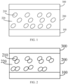
- the heating layer 200 includes metal powder particles and an inorganic oxide matrix 220.
- the metal powder particles are distributed in the inorganic oxide matrix 220.
- the metal powder particles are filled in at least a part of the pores of the inorganic oxide matrix 220.
- a plurality of particle aggregates 210 is formed by the metal powder particles.
- the plurality of particle aggregates 210 are arranged in a thickness direction of the heating layer 200.
- the particle aggregates have a metallic luster, and the remaining gelatinous materials are the inorganic oxide matrix.
- the inventor has found that after the plurality of metal powder particles in the heating layer 200 is aggregated to form the particle aggregates 210, heat in the heating layer 200 may be quickly transferred along the granular aggregates 210 to improve heating efficiency of the heating layer 200. Further, the formed particle aggregates 210 are distributed in the thickness direction of the heating layer 200, enabling heat generated by the heating layer 200 to be uniformly transferred to both sides of the heating layer 200 to improve heating uniformity of the heating layer 200. Thus aggregation of the heat on one side of the heating layer 200 is reduced, and stability of the heat-generating assembly is improved.
- the inorganic oxide matrix 220 may disperse thermal stress generated by the particle aggregated 210 during the heating, to reduce risks of cracking and the inter-layer peeling of the heating layer 200 and prolong service life of the heat-generating assembly.
- particle aggregates in the present disclosure may be understood as aggregates formed by bringing a plurality of metal particles to be in contact with each other.
- a pore (not illustrated in figures) is formed at a connection between the particle aggregate 210 and the inorganic oxide matrix 220.
- the pores in the inorganic oxide matrix 220 each have a smaller size than the pore at the connection between the particle aggregate 210 and the inorganic oxide matrix 220.
- the inventor has found that when the size of each pore in the inorganic oxide matrix 220 is too great, an adhesive strength between the inorganic oxide matrixes 220 is weak, and adhesion is not firm, which may result in a fracture during the heating.
- the pore of small size, of the inorganic oxide matrix 220 can improve stability of the inorganic oxide matrix 220 in structure and the adhesive strength between the inorganic oxide matrixes 220, to reduce the risk of the inter-layer peeling of the heating layer 200 and prolong the service life of the heat-generating assembly.
- the metal powder particles in the above heating layer 200 include a weak magnetic metal material.
- the weak magnetic metal material refers to a metal material having a relative permeability smaller than 1.
- a type of the weak magnetic metal material is not limited, and may be selected by a person skilled in the art as desired.
- the weak magnetic metal material may be silver, aluminum, copper, or the like.
- the inorganic oxide matrix in the above heating layer 200 may be any inorganic oxide having pores.
- the inorganic oxide matrix may include at least one of silicon oxide, bismuth oxide, magnesium oxide, or potassium oxide.
- a content of the inorganic oxide matrix 220 in the heating layer 200 ranges from 10% to 40% (mass percentage), and a content of the weak magnetic metal material ranges from 60% to 90% (mass percentage).
- an area of the heating layer 200 in the heat-generating assembly is not particularly limited.
- an orthographic projection of the heating layer 200 on the first non-metal plate 100 or on the second non-metal plate 300 is smaller than or equal to an area of the first non-metal plate 100 or an area of the second non-metal plate 300. That is, the area of the heating layer 200 is the same as or smaller than the area of the first non-metal plate 100 or the area of the second non-metal plate 300.
- the term "area is the same" in the present disclosure should be understood in a broad sense. That is, the area of the heating layer 200 may not be strictly controlled to be absolutely identical with that of the first non-metal plate 100 or the second non-metal plate 300, and may be approximately the same, for example, as long as no significant area difference is observed by naked eyes.
- a specific forming manner of the heating layer 200 is not specially limited, and may be selected and set by those skilled in the art as desired.
- the heating layer 200 may be formed by adhering a metal film layer on the first non-metal plate 100 and the second non-metal plate 300, or may be formed by performing a water transfer printing processing on the first non-metal plate 100 and the second non-metal plate 300, or may be formed through thermal spraying on the first non-metal plate 100 and the second non-metal plate 300.
- Specific conditions of adhering the metal film layer, the water transfer printing processing, and the thermal spraying are not particularly limited in the present disclosure, as long as a uniform and flat heating layer 200 can be formed.
- the heating layer 200 may be connected to the first non-metal plate 100 and the second non-metal plate 300 by sintering and curing.
- the heating layer 200 may be firmly bonded with the first non-metal plate 100 and the second non-metal plate 300.
- a sintering and curing temperature of the heating layer 200 is smaller than a softening temperature of the first non-metal plate 100 and the second non-metal plate 300.
- the first non-metal plate 100 and/or the second non-metal plate 300 would not be deformed.
- the heating layer 200 when the heating layer 200 is connected to the first non-metal plate 100 and the second non-metal plate 300 by the sintering and curing, the heating layer 200 and the non-metal plate (at least one of the first non-metal plate 100 and the second non-metal plate 300) may be mutually embedded at an interface at which they are in contact with each other, and thus the interface is not a flat interface.
- the heating layer 200 may further be connected to the first non-metal plate 100 and/or the second non-metal plate 300 by heating a hardened adhesive layer.
- the heating layer 200 is connected to the first non-metal plate 100 by the sintering and curing, and is connected to the second non-metal plate 300 through the adhesive layer.
- thermal resistance between the heating layer 200 and the second non-metal plate 300 can be improved, transfer rate of the heat to the second non-metal plate 300 is reduced, and transfer efficiency of the heat to the first non-metal plate 100 is increased, which further increases the utilization rate of the heat.
- the sintering and curing temperature of the heating layer 200 is smaller than the softening temperature of the first non-metal plate 100.
- a heating and hardening temperature of the adhesive layer is smaller than the softening temperature of the second non-metal plate 300. Therefore, the heating layer 200 may be firmly bonded to the first non-metal plate 100 and the second non-metal plate 300. In addition, during connecting, the first non-metal plate 100 and the second non-metal plate 300 are not deformed.
- the heating layer 200 may be connected to the first non-metal plate 100 by the adhesive layer, and may be connected to the second non-metal plate 300 by the sintering and curing. Therefore, thermal resistance between the heating layer 200 and the first non-metal plate 100 can be improved, transfer rate of the heat to the first non-metal plate 100 is reduced, and transfer efficiency of the heat to the second non-metal plate 300 is increased. Thus, the utilization rate of the heat is increased.
- the heating and hardening temperature of the adhesive layer is smaller than the softening temperature of the first non-metal plate 100.
- the sintering and curing temperature of the heating layer 200 is smaller than the softening temperature of the first non-metal plate 100. Therefore, the heating layer 200 may be firmly bonded to the first non-metal plate 100 and the second non-metal plate 300. In addition, during the connecting, the first non-metal plate 100 and the second non-metal plate 300 are not deformed.
- the heating layer 200 is connected to both the first non-metal plate 100 and the second non-metal plate 300 through the adhesive layer. It should be noted herein that the heating and hardening temperature of the adhesive layer is smaller than the softening temperature of each of the first non-metal plate 100 and the second non-metal plate 300. Therefore, the heating layer 200 may be firmly bonded to the first non-metal plate 100 and the second non-metal plate 300. In addition, during the connecting, the first non-metal plate 100 and the second non-metal plate 300 are not deformed.
- the arrangement of the particle aggregates 210 in the heating layer 200 is not particularly limited, and may be designed by a person skilled in the art based on product requirements.
- the plurality of particle aggregates 210 is arranged at intervals in the thickness direction of the heating layer 200.
- the plurality of particle aggregates 210 is arranged to be adjoined to each other in the thickness direction of the heating layer 200. It should be noted herein that the particle aggregates 210 arranged to be adjoined to each other are not limited to two particle aggregates, and may include three or more particle aggregates.
- the particle aggregates 210 arranged to be adjoined to each other or at intervals can disperse the thermal stress generated to facilitate absorption of the inorganic oxide matrix 220 to the thermal stress, which can improve stability of the resistance of the heat-generating assembly.
- a part of the plurality of particle aggregates 210 is arranged at intervals in the thickness direction of the heating layer 200, and the remaining are arranged to be adjoined to each other in the thickness direction of the heating layer 200. That is, the arrangement of the plurality of particle aggregates 210 in the heating layer 200 includes a combination of the arrangement of the particle aggregates 210 at intervals and the arrangement of the particle aggregates 210 adjoined to each other.
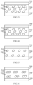
- the plurality of particle aggregates 210 is arranged at intervals in an extending direction of the first non-metal plate 100 and/or the second non-metal plate 300. This arrangement of the particle aggregates 210 is illustrated in a dotted region in FIG. 3 .
- the heat in the heating layer 200 can be quickly transferred along the particle aggregates 210 to improve the heating efficiency of the heating layer 200.
- the plurality of particle aggregates 210 is arranged at intervals in the extending direction of the first non-metal plate 100 and/or the second non-metal plate 300, the heat generated by the heating layer 200 can be uniformly transferred to both sides of the heating layer 200.
- heating uniformity of the heating layer 200 can be improved, and the aggregation of the heat on one side of the heating layer 200 can be reduced, which can improve the stability of the heat-generating assembly.
- the inorganic oxide matrix 220 can disperse the thermal stress generated by the particle aggregates 210 during the heating to reduce the risks of the cracking and the inter-layer peeling of the heating layer 200 and prolong the service life of the heat-generating assembly.
- the plurality of particle aggregates 210 is staggered with each other in the thickness direction of the heating layer 200.
- This arrangement of the particle aggregates 210 is illustrated in a dotted region in FIG. 4 .
- the heat in the heating layer 200 can be quickly transferred along the particle aggregates 210 to improve the heating efficiency of the heating layer 200.
- the formed particle aggregates 210 are staggered with each other in the thickness direction of the heating layer 200, the heat generated by the heating layer 200 can be uniformly transferred to both sides of the heating layer 200.
- the heating uniformity of the heating layer 200 can be improved, and the aggregation of the heat on one side of the heating layer 200 can be reduced, which can improve the stability of the heat-generating assembly.
- the inorganic oxide matrix 220 can disperse the thermal stress generated by the particle aggregate 210 during the heating to reduce the risks of the cracking and the inter-layer peeling of the heating layer 200 and prolong the service life of the heat-generating assembly.
- the plurality of particle aggregates 210 is arranged in a same direction along the extending direction of the first non-metal plate 100 and/or the second non-metal plate 300. That is, the particle aggregates 210 indicated in the dotted region in FIG. 3 are arranged in the same direction along the extending direction of the first non-metal plate 100 and/or the second non-metal plate 300. In some embodiments, the particle aggregates 210 may be arranged parallel to the first non-metal plate 100 and the second non-metal plate 300.
- the parallel arrangement herein is not an absolute parallel arrangement, and should mean that an entirety of the particle aggregates 210 is substantially parallel to the first non-metal plate 100 and the second non-metal plate 300.
- the inventor has found that when the particle aggregates 210 are arranged in the extending direction of the first non-metal plate 100 and the second non-metal plate 300, the heat in the heating layer 200 can be quickly transferred along the particle aggregates 210. Thus, the heating efficiency of the heating layer 200 can be improved.
- the heating uniformity of the heating layer 200 can be improved, and the aggregation of the heat on one side of the heating layer 200 can be reduce, which can improve the stability of the heat-generating assembly.
- the inorganic oxide matrix 220 may disperse the thermal stress generated by the particle aggregate 210 during the heating to reduce the risks of the cracking and the inter-layer peeling of the heating layer 200 and prolong the service life of the heat-generating assembly.
- the particle aggregates 210 formed by aggregating different metal powders in the heating layer 200 are necessarily not exactly the same as each other in size and shape.
- the particle aggregates 210 may be of an irregular shape.
- the particle aggregate 210 has a long axis extending in the extending direction of the first non-metal plate 100 and/or the second non-metal plate 300, and a short axis extending in the thickness direction of the heating layer 200.
- the particle aggregates 210 are each shaped to allow the long axis thereof to be close to the first non-metal plate 100 and the second non-metal plate 300 as much as possible to increase a heat transfer area between the particle aggregate 210 and the first non-metal plate 100 and the second non-metal plate 300, thereby increasing the utilization rate of the heat of the heating layer 200. Meanwhile, the particle aggregates 210 are arranged in the same direction as a whole. Thus, it is possible to improve the uniformity of the transferred heat, and reduce the aggregation of the heat on the heating layer 200 and the thermal stress generated in the heating layer 200 during the heating. Thus, the risks of the cracking and the inter-layer peeling of the heating layer 200 can be reduced.
- the long axis refers to a longest line segment formed by connecting two points on the particle aggregate 210, and the long axis direction is an extending direction along the longest line segment.
- a short axis refers to a shortest line segment formed by connecting two points on the particle aggregate 210, and the short axis direction is an extending direction along the line shortest segment.
- the plurality of particle aggregates 210 is arranged in layers in the thickness direction of the heating layer 200.
- the thickness direction of the heating layer 200 in each of the layers may include the plurality of particle aggregates 210.
- the particle aggregates in each of the layers are arranged at intervals in the extending direction of the first non-metal plate 100 and/or the second non-metal plate 300.
- the particle aggregates in each of the layers are arranged to be adjoined to each other in the extending direction of the first non-metal plate 100 and/or the second non-metal plate 300.
- the heat in the heating layer 200 may be quickly transferred along the particle aggregates 210 to improve the heating efficiency of the heating layer 200. Further, since the particle aggregates in each of the layers are arranged at intervals and/or adjoined to each other in the extending direction of the first non-metal plate 100 and/or the second non-metal plate 300, the heating uniformity of the heating layer 200 can be improved, and the aggregation of heat on one side of the heating layer 200 can be reduced, which can improve the stability of the heat-generating assembly.
- the inorganic oxide matrix 220 can disperse the thermal stress generated by the particle aggregate 210 during the heating to reduce the risks of the cracking and the inter-layer peeling of the heating layer 200 and prolong the service life of the heat-generating assembly.
- two adjacent layers of the particle aggregates 210 are connected by the inorganic oxide matrix 220.
- the inorganic oxide matrix 220 has the pores, the heat in the heating layer 200 can be quickly transferred along the particle aggregates 210 to improve the heating efficiency of the heating layer 200 and the heating uniformity of the heating layer 200 and reduce the aggregation of the heat on one side of the heating layer 200, which can improve the stability of the heat-generating assembly.
- the inorganic oxide matrix 220 can disperse the thermal stress generated by the particle aggregate 210 during the heating to reduce the risks of the cracking and the inter-layer peeling of the heating layer 200 and prolong the service life of the heat-generating assembly.
- the plurality of particle aggregates 210 is arranged away from the first non-metal plate 100 and/or the second non-metal plate 300. That is, there is a predetermined distance between the particle aggregate 210 and the first non-metal plate 100 and the second non-metal plate 300.
- the particle aggregates 210 may be spaced apart from the first non-metal plate 100 and/or the second non-metal plate 300 by the inorganic oxide matrix 220.
- the inorganic oxide matrix 220 it is possible to improve the uniformity of heat transfer to the non-metal plate, reduce a risk of excessive noise due to too high heating power, and reduce possibility of cracking of the non-metal plates.
- the plurality of particle aggregates 210 in the heating layer 200 is arranged away from a middle region of the heating layer 200. That is, the middle region of the heating layer 200 is not a region where the particle aggregates 210 are distributed by a greatest density. Therefore, the particle aggregates 210 are distributed in the middle region of the heating layer 200 by a relatively small density. Thus, it is possible to avoid the heat from being accumulated in the middle part of the heating layer 200 during the heating, which may result in the inter-layer peeling of the heating layer 200.
- the heating layer 200 it is possible to avoid the peeling of the heating layer 200 from occurring in a region where the particle aggregates 210 are distributed at a relatively greater density and a region where the inorganic oxide matrixes 220 are distributed by a relatively greater density. Meanwhile, bubbles generated during the heating can be reduced. Further, it is possible to prevent an air layer from being formed in the middle region of the heating layer 200. The inventor has found that when the air layer is formed in the middle region of the heating layer 200, electrical parameters and inductive resistance of the heating layer 200 may be affected, and thus the heating effect would be affected.
- the heating layer 200 is embedded into the first non-metal plate 100 and/or the second non-metal plate 300, and thus a contact interface between the heating layer 200 and the first non-metal plate 100 and/or the second non-metal plate 300 is a concave-convex interface. Therefore, when a contact point on the heating layer 200 with the first non-metal plate 100 and the second non-metal plate 300 is a convex point, contact points on the first non-metal plate 100 and the second non-metal plate 300 with the heating layer 200 are correspondingly concave points.
- the contact point on the heating layer 200 with the first non-metal plate 100 and the second non-metal plate 300 is a concave point
- the contact points on the first non-metal plate 100 and the second non-metal plate 300 with the heating layer 200 are convex points. Therefore, adhesion between the heating layer 200 and the first non-metal plate 100 and the second non-metal plate 300 is better to increase the heat utilization rate.
- a heat-generating assembly in another aspect of the present disclosure, includes two non-metal plates, and a heating layer 200 located between the non-metal plates.
- the non-metal plates include a first non-metal plate 100 and a second non-metal plate 300.
- the first non-metal plate 100 and the second non-metal plate 300 are arranged in parallel.
- the heating layer 200 includes metal powder particles and an inorganic oxide matrix 220.
- the metal powder particles in the heating layer 200 are distributed in the inorganic oxide matrix 220.
- a plurality of particle aggregates 210 is formed by the metal powder particles.
- the plurality of particle aggregates 210 are arranged at intervals and/or adjoined to each other in a thickness direction of the heating layer 200.
- a content of the metal powder particles follows a changing trending of increasing, then decreasing, and then increasing again.
- the middle region is not a heat concentration region. Thu, it is possible to prevent the inter-layer peeling of the heating layer due to the heating to improve the service life of the heat-generating assembly and the uniformity of heat transfer.
- the content of the metal powder particles follows a changing trend of increasing, then decreasing, and then increasing again, and then decreasing again.
- a content of silicon, oxygen, or aluminum element follows a changing trending of decreasing, then increasing, then decreasing again, and then increasing again. It should be noted herein that in the region where the content of the metal powder particles decreases, the content of the silicon, oxygen, or aluminum element increases correspondingly.
- the inorganic oxide matrix is located in a region where the content of the silicon, oxygen, or aluminum element increases.
- the material of the inorganic oxide matrix 220 is not particularly limited.
- the inorganic oxide matrix 220 may be selected from at least one of SiO 2 , Bi 2 O 3 , Al 2 O 3 , B 2 O 3 , ZnO, TiO 2 and Na 2 O.
- the metal powder may be a weak magnetic metal material. It should be noted herein that the weak magnetic metal material refers to a metal material having a relative permeability smaller than 1.
- a type of the weak magnetic metal material is not limited, and may be selected by a person skilled in the art as desired.
- the weak magnetic metal material may be silver, aluminum, copper, or the like.
- the content of the metal powder particles accounts for 60% to 90% of the total mass of the heating layer.
- the metal powder particles are aggregated to form the particle aggregates.
- the heating efficiency and the heating uniformity of the heat-generating assembly can be improved.
- a pore is formed between the particle aggregates, and thus it is possible to reduce the thermal stress generated during the heating and the risk of the cracking and the inter-layer peeling of the heating layer 200.
- the particle aggregates 210 are arranged in the extending direction of the first non-metal plate 100 and/or the second non-metal plate 300.
- a cooking appliance in yet another aspect of the present disclosure, includes a container body 1200 and the heat-generating assembly as described above.
- the heat-generating assembly 1100 is disposed in the container body 1200.
- the first non-metal plate is arranged towards an upper end of the container body 1200 on the heat-generating assembly 1100. Therefore, the cooking appliance has all the features and advantages of the heat-generating assembly 1100 as described above, and the description thereof in detail will be omitted herein. In general, the advantages such as fast heat transfer, good heat transfer stability, and long service life can be at least provided.
- the heat-generating assembly 1100 is formed as a bottom of the container body 1200.
- the heat-generating assembly 1100 is detachably connected to side walls of the container body 1200. In some embodiments, this connection may be done through welding or in other manners, and may be implemented by a person skilled in the art as desired, as long as good assembly can be realized.
- the second non-metal plate 300 when the first non-metal plate 100 is the surface in contact with an object to be heated and the second non-metal plate 300 is the surface away from the object to be heated, the second non-metal plate 300 has a greater thickness than the first non-metal plate 100. Thus, it is possible to shorten the distance by which the heat is transferred to the first non-metal plate 100, which can improve the heat transfer rate and the heat utilization rate.
- a speed at which the heat generated by the heated the heating layer 200 is transferred to the first non-metal plate 100 is set greater than a speed at which the generated heat is transferred to the second non-metal plate 300.
- the materials of the first non-metal plate 100 and the second non-metal plate 300 are not particularly limited, and may be selected by those skilled in the art as desired.
- the first non-metal plate 100 and the second non-metal plate 300 may each independently include one of ceramic, microcrystalline glass, and high borosilicate glass.
- the microcrystalline glass transparent microcrystalline glass, microcrystalline glass with an expansion coefficient of zero, surface-reinforced microcrystalline glass, different-color or machinable microcrystalline glass may be obtained by controlling a type, the number, a size and the like of crystallites.
- the microcrystalline glass has dual characteristics of the glass and the ceramic.
- the microcrystalline glass consists of crystals. That is, atomic arrangement of the microcrystalline glass is regular. Therefore, the microcrystalline glass has a higher brightness than the ceramic, and a stronger toughness than the glass. Thus, it is possible to satisfy higher requirements of the consumer.
- the high borosilicate glass has low coefficient of thermal expansion, high physical strength, and stronger crash resistance. Thus, the service life of the heat-generating assembly can be prolonged.
- both the first non-metal plate 100 and the second non-metal plate 300 may be made of the ceramic.
- the ceramic has an appearance effect such as jade, and superior heat dissipation effect in the inorganic material. Therefore, on the one hand, when applied to a health-preserving kettle, the first non-metal plate 100 and the second non-metal plate 300 made of the ceramic can form a consistent visual effect with side walls of the ceramic appearance of the health-preserving kettle, which can improve user experience. On the other hand, heat dissipation is facilitated.
- both the first non-metal plate 100 and the second non-metal plate 300 may be made of glass. Therefore, a glass kettle in which a bottom and side walls thereof are integrated may be formed, and an inorganic layer on an inner side may be thinner, which can significantly reduce the overall thickness of the heat-generating assembly 1100.
- an inner glass may also be made of the microcrystalline glass or high borosilicate glass.
- the glass of the first non-metal plate 100 and the second non-metal plate 300 close to water or food to be heated may be a glass material with higher thermal conductivity coefficient, and an outer side may be made of a material with lower thermal conductivity coefficient.
- the heat of the heating layer 200 can be quickly and more preferably transferred to the water or food to be heated.
- the heating efficiency can be improved.
- overheating of the heat-generating assembly can be avoided.
- the bottom and the side walls are made of an integrated glass, and thus a process is relatively simple during the manufacturing of the product.
- one side of each of the first non-metal plate 100 and the second non-metal plate 300 is made of the glass, and the other side is made of the ceramic.
- the non-metal plate located at the side of the heating surface of the heat-generating assembly 1100 is made of the ceramic, and the other non-metal plate is made of the glass. Since the ceramic has advantages such as high density, water-proof, and quick heat dissipation, when heating the heat-generating assembly 1100, the heat can be quickly transferred to the water or food to be heated via the ceramic material.
- the non-metal plate located at the side of the heating surface of the heat-generating assembly 1100 is made of the glass, and the other non-metal plate is made of the ceramic. In this case, since a mechanical strength of the ceramic material is better than that of the glass material, an outer side of the heat-generating assembly 1100 can be protected to a certain extent.
- a cooking device in still yet another aspect of the present disclosure, includes a base 3000, and the cooking appliance 1000 as described above. Therefore, the cooking device 2000 has all the features and advantages of the cooking appliance 1000 as described above, and the description thereof in detail will be omitted herein. In general, the advantages such as fast heat transfer, uniform heat transfer, and long service life can be at least provided.
- first and second are only used for descriptive purposes, and cannot be understood as indicating or implying relative importance or implicitly indicating the number of indicated technical features. Therefore, the features associated with “first” and “second” may explicitly or implicitly include at least one of the features.
- “plurality” means at least two, such as two, three, etc., unless otherwise preferably defined.
- the first feature "on” or “under” the second feature may mean that the first feature is in direct contact with the second feature, or the first and second features are in indirect contact through an intermediate.
- the first feature "above” the second feature may mean that the first feature is directly above or obliquely above the second feature, or simply mean that the level of the first feature is higher than that of the second feature.
- the first feature "below” the second feature may mean that the first feature is directly below or obliquely below the second feature, or simply mean that the level of the first feature is smaller than that of the second feature.
Landscapes
- Engineering & Computer Science (AREA)
- Food Science & Technology (AREA)
- Chemical & Material Sciences (AREA)
- Ceramic Engineering (AREA)
- Manufacturing & Machinery (AREA)
- Physics & Mathematics (AREA)
- Electromagnetism (AREA)
- Surface Heating Bodies (AREA)
- Resistance Heating (AREA)
Abstract
Description
- The present disclosure relates to the technical field of household appliances, and more particularly, to a heat-generating assembly, a cooking appliance, and a cooking device.
- Existing cooking appliances have used many inorganic materials such as ceramic and glass. For example, an electric stewpot has a ceramic liner, a glass health kettle has a liner made of glass material, and a microcrystal pot, a ceramic pot or the like are usable with an induction cooker or the like. These inorganic materials have very good chemical stability, and are healthy and environmentally friendly. However, these inorganic materials may have many defects, such as low heat transfer efficiency, poor toughness, being fragile, and the like. A conventional heating method mainly adopts a heat-generating assembly such as a heat-generating tube and a heat-generating plate. Glassware is brought into contact with the heat-generating tube and the heat-generating plate for heat transfer. In such a heating method, although an overall assembly is simple, there are significant problems. For example, a contact area is too small to realize close contact, which may result in low heat transfer efficiency. Thus, a time required for heating water of 1 liter by a kettle by this method would exceed 15 min. This method is improved for thermal efficiency by related manufacturers. However, less effect is obtained. Further, some manufacturers adopt a thick film heating or the like to print a thick film circuit on a glass plate for heating. This solution has high thermal efficiency and uniform heating with high requirement for the glass. For example, quartz glass or the like of temperature-resistant should be employed. In addition, a safety problem also exists. In a case where the glass is broken, great current may generate a great hidden danger to the safety of a consumer. Similar solutions may adopt printing of tin oxide, thermal spraying of heat-generating wires, and the like.
- Therefore, the current heat-generating assembly also needs to be further improved.
- The present disclosure aims to solve at least one of the technical problems in the related art to some extent. To this end, an object of the present disclosure is to provide a heat-generating assembly, a cooking appliance, and a cooking device. The heat-generating assembly has advantages such as high heat transfer efficiency, uniform heat transfer, and high heating stability, to remarkably improve cooking effects and service life of the cooking device and the cooking appliance including the heat-generating assembly.
- According to an aspect of the present disclosure, a heat-generating assembly is provided. The heat-generating assembly includes two non-metal plates, a heating layer located between the non-metal plates. The heating layer includes an inorganic oxide matrix, and metal powder particles distributed in the inorganic oxide matrix. In at least part of the heating layer, a plurality of particle aggregates is formed by the metal powder particles and arranged in a thickness direction of the heating layer. Therefore, heating efficiency, heating uniformity and heating stability of the heat-generating assembly are improved. Meanwhile, thermal stress generated during the heating is reduced, and risks of cracking and inter-layer peeling of the heating layer are reduced.
- According to some embodiments of the present disclosure, in the at least part of the heating layer, the plurality of particle aggregates is arranged at intervals and/or adjoined to each other in the thickness direction of the heating layer. Therefore, the thermal stress generated during the heating is reduced, and absorption of the inorganic oxide matrix for the thermal stress is facilitated. Thus, stability of resistance of the heat-generating assembly is improved, and appearance effect of the heat-generating assembly is improved.
- According to some embodiments of the present disclosure, in the at least part of the heating layer, the plurality of particle aggregates is arranged at intervals in an extending direction of the non-metal plates. Thus, the non-metal plates are uniformly heated.
- According to some embodiments of the present disclosure, in the at least part of the heating layer, the plurality of particle aggregates is staggered with each other in the thickness direction of the heating layer. Therefore, the non-metal plates are uniformly heated, and a risk of a fracture of the non-metal plates is reduced.
- According to some embodiments of the present disclosure, in the at least part of the heating layer, the particle aggregates are connected to each other by the inorganic oxide matrix, and the inorganic oxide matrix has pores. Therefore, the thermal stress generated during the heating is reduced, and risks of the cracking and the peeling of the heating layer are reduced.
- According to some embodiments of the present disclosure, a pore is formed at a connection of the particle aggregate and the inorganic oxide matrix. The pores in the inorganic oxide matrix each have a smaller size than the pore at the connection between the particle aggregate and the inorganic oxide matrix. Therefore, the size of each pore in the inorganic oxide matrix is small, which can improve stability of the inorganic oxide matrix structure, and reduce the risk of inter-layer peeling of the heating layer.
- According to some embodiments of the present disclosure, the plurality of particle aggregates is arranged in a same direction along the extending direction of the non-metal plates. Thus, the non-metal plates are uniformly heated.
- According to some embodiments of the present disclosure, the plurality of particle aggregates is arranged parallel to the non-metal plates. Therefore, the non-metal plates are uniformly heated, and the risk of fracture of the non-metal plates is reduced.
- According to some embodiments of the present disclosure, the particle aggregate is of an irregular shape. The particle aggregate has a long axis extending in an extending direction of the non-metal plates, and a short axis extending in the thickness direction of the heating layer. Therefore, the heating efficiency is improved, heat transfer is uniform, and risk of cracking and peeling of the heating layer is reduced.
- According to some embodiments of the present disclosure, in the at least part of the heating layer, the plurality of particle aggregates is arranged in layers in the thickness direction of the heating layer. The particle aggregates in each of the layers are arranged at intervals and/or adjoined to each other in an extending direction of the non-metal plates. Therefore, the heating efficiency is improved, heat transfer is uniform, and risk of cracking and peeling of the heating layer is reduced.
- According to some embodiments of the present disclosure, in the at least part of the heating layer, two adjacent layers of particle aggregates are connected by the inorganic oxide matrix. Therefore, uniformity of heat transfer is improved, and aggregation of heat in the heating layer is reduced.
- According to some embodiments of the present disclosure, in the at least part of the heating layer, the plurality of particle aggregates is arranged away from the non-metal plates, and spaced apart from the non-metal plates by the inorganic oxide matrix. Therefore, the uniformity of heat transfer is improved, the non-metal plates are prevented from being broken, and noise during the heating is reduced to a certain extent.
- According to some embodiments of the present disclosure, in the at least part of the heating layer, the plurality of particle aggregates in the heating layer is arranged away from a middle region of the heating layer. Therefore, it is avoided that the heat is aggregated in a middle part of the heating layer to cause the heating layer to peeling, and bubbles generated in the heat-generating assembly are avoided to a certain extent.
- According to some embodiments of the present disclosure, the heating layer is embedded into the non-metal plate. A contact interface between the heating layer and the non-metal plate is a concave-convex interface. Thus, uniformity of heat transfer to the non-metal plate is improved.
- According to some embodiments of the present disclosure, the non-metal plates are different in thickness.
- According to another aspect of the present disclosure, a heat-generating assembly is provided. The heat-generating assembly includes two non-metal plates, and a heating layer located between the non-metal plates. The heating layer includes metal powder particles and an inorganic oxide matrix. The metal powder particles are distributed in the inorganic oxide matrix. In at least part of the heating layer, along a thickness direction of the heating layer, a content of the metal powder particles follows a changing trend of increasing, then decreasing, and then increasing again. Therefore, the heat is prevented from being aggregated in the middle part of the heating layer, and the uniformity of heat transfer is improved.
- According to some embodiments of the present disclosure, in the at least part of the heating layer, along the thickness direction of the heating layer, from one side surface to the other side surface of the heating layer, the content of the metal powder particles follows a changing trend of increasing, then decreasing, then increasing again, and then decreasing again. Therefore, the uniformity of heat transfer is improved.
- According to some embodiments of the present disclosure, in the at least part of the heating layer, along the thickness direction of the heating layer, from one side surface to the other side surface of the heating layer, a content of silicon, oxygen, or aluminum element follows a changing trend of decreasing, then increasing, then decreasing again, and then increasing again.
- According to some embodiments of the present disclosure, in the at least part of the heating layer, along the thickness direction of the heating layer, from one side surface to the other side surface of the heating layer, the content of the silicon, oxygen, or aluminum element increases in a region where the content of the metal powder particles decreases, and/or in the at least part of the heating layer, along the thickness direction of the heating layer, from one side surface to the other side surface of the heating layer, the content of silicon, oxygen, or the aluminum decreases in a region where the content of the metal powder particles increases.
- According to some embodiments of the present disclosure, in the at least part of the heating layer, along the thickness direction of the heating layer, from one side surface to the other side surface of the heating layer, the metal powder particles are aggregated to form the particle aggregates in a region where the content of the metal powder particles increases. Therefore, the heating efficiency and the heating uniformity of the heat-generating assembly are improved. Meanwhile, the thermal stress generated during the heating is reduced, and risk of the cracking and the inter-layer peeling of the heating layer is reduced.
- According to some embodiments of the present disclosure, the particle aggregates are arranged in an extending direction of the non-metal plates. Thus, the heat is facilitated to be transferred to the non-metal plates.
- According to some embodiments of the present disclosure, the inorganic oxide matrix is located in a region where the content of the silicon, oxygen, or aluminum element increases.
- According to some embodiments of the present disclosure, the inorganic oxide matrix is made of a material including at least one of SiO2, Bi2O3, Al2O3, B2O3, ZnO, TiO2 and Na2O; and/or the metal powder particle is any one of silver, copper, and aluminum; and/or a content of the metal powder particles accounts for 60% to 90% of the total mass of the heating layer.
- According to yet another aspect of the present disclosure, a cooking appliance is provided. The cooking appliance includes a container body, and the heat-generating assembly as described above. The heat-generating assembly is disposed in the container body. Therefore, the cooking appliance has all the features and advantages of the heat-generating assembly described above, and the description thereof in detail will be omitted herein. In general, the cooking appliance at least has advantages such as fast and uniform heat transfer, good heating stability, and long service life.
- According to some embodiments of the present disclosure, a thickness of the non-metal plate close to an object to be heated is smaller than a thickness of the non-metal plate away from the object to be heated. Therefore, utilization rate of the heat is increased, and cracking of the second non-metal plate is reduced to a certain extent.
- According to still yet another aspect of the present disclosure, a cooking device is provided. The cooking device includes a base, and the cooking appliance described above. Therefore, the cooking device has all the features and advantages of the cooking appliance described above, and the description thereof in detail will be omitted herein. In general, the cooking device at least has advantages such as fast and uniform heat transfer, good heating stability, and long service life.
- The above and/or additional aspects and advantages of the present disclosure will become more apparent and more understandable from the description of embodiments taken in conjunction with the accompanying drawings, in which:
-
FIG. 1 is a schematic structural view showing a heat-generating assembly according to an embodiment of the present disclosure. -
FIG. 2 is a schematic structural view showing a heat-generating assembly according to another embodiment of the present disclosure. -
FIG. 3 is a schematic structural view showing a heat-generating assembly according to another embodiment of the present disclosure. -
FIG. 4 is a schematic structural view showing a heat-generating assembly according to another embodiment of the present disclosure. -
FIG. 5 is a schematic structural view showing a heat-generating assembly according to another embodiment of the present disclosure. -
FIG. 6 is a schematic structural view showing a heat-generating assembly according to another embodiment of the present disclosure -
FIG. 7 is a schematic structural view showing a heat-generating assembly according to another embodiment of the present disclosure. -
FIG. 8 is a schematic structural view showing a heat-generating assembly according to another embodiment of the present disclosure. -
FIG. 9 is a schematic structural view showing a heat-generating assembly according to another embodiment of the present disclosure. -
FIG. 10 is an element content distribution view showing a heat-generating assembly according to another embodiment of the present disclosure. -
FIG. 11 is a schematic structural view showing a cooking appliance according to an embodiment of the present disclosure. -
FIG. 12 is a schematic structural view showing a cooking device according to an embodiment of the present disclosure. - 100: first non-metal plate; 200: heating layer; 210: particle aggregate; 220: inorganic oxide matrix; 300: second non-metal plate; 1000: cooking appliance; 1100: heat-generating assembly; 1200: container body; 2000: cooking device; 3000: base.
- Embodiments of the present disclosure are described below in detail. The embodiments described below are exemplary and merely used to explain the present disclosure, rather than being construed as limitation on the present disclosure. The specific techniques or conditions not indicated in the embodiments are implemented based on the techniques or conditions described in the related art or based on product specifications. Adopted reagents or instruments, where a manufacturer is not specified, are all conventional products commercially available.
- In an aspect of the present disclosure, a heat-generating assembly is provided. Referring to
FIG. 1 andFIG. 7 , the heat-generating assembly includes two non-metal plates, and aheating layer 200 located between the non-metal plates. The two non-metal plates are a firstnon-metal plate 100 and a secondnon-metal plate 300, respectively. In some embodiments, the firstnon-metal plate 100 and the secondnon-metal plate 300 are arranged opposite to each other at intervals. In some embodiments, the firstnon-metal plate 100 and the secondnon-metal plate 300 are arranged in parallel. Theheating layer 200 is located in a spacing between the firstnon-metal plate 100 and the secondnon-metal plate 300. According to some embodiments of the present disclosure, a thickness of the secondnon-metal plate 300 is not particularly limited, and may be selected by a person skilled in the art as desired. In some embodiments, as the thickness of the secondnon-metal plate 300 increases, a temperature difference inside the secondnon-metal plate 300 also increases during the heating, and thermal stress increases. On the contrary, the smaller the thickness of the secondnon-metal plate 300, the strength decreases accordingly, and a risk of cracking during the arrangement of theheating layer 200 is also improved accordingly. Therefore, the thickness of the secondnon-metal plate 300 may be adjusted and selected based on specific needs of the thermal stress, mechanical strength and the like. - According to some embodiments of the present disclosure, a thickness of the first
non-metal plate 100 is not particularly limited, and may be selected by a person skilled in the art as desired. Similarly, as the thickness of the firstnon-metal plate 100 increases, mechanical strength of the firstnon-metal plate 100 increases, and a risk of collision may be reduced to some extent during use. On the contrary, when the thickness of the firstnon-metal plate 100 is too small, the mechanical strength of the firstnon-metal plate 100 decreases. Therefore, the thickness of the firstnon-metal plate 100 may be selected by a person skilled in the art as desired. Meanwhile, during use of the heat-generating assembly, when the firstnon-metal plate 100 is a surface in contact with an object to be heated, the secondnon-metal plate 300 is a surface away from the object to be heated. In this case, the thickness of the secondnon-metal plate 300 should be greater than the thickness of the firstnon-metal plate 100 to shorten a distance by which the heat is transferred to the firstnon-metal plate 100. Thus, heat transfer rate is increased, and heat utilization rate is improved. Otherwise, the thickness of the firstnon-metal plate 100 is greater than the thickness of the secondnon-metal plate 300. In addition, the firstnon-metal plate 100 and the secondnon-metal plate 300 may be made of a material selected by a person skilled in the art as desired, as long as the material has high temperature resistance. For example, the firstnon-metal plate 100 and the secondnon-metal plate 300 each independently are made of one of ceramic, microcrystalline glass, and high borosilicate glass. In some embodiments, both the firstnon-metal plate 100 and the secondnon-metal plate 300 may be made of the ceramic, or both the firstnon-metal plate 100 and the secondnon-metal plate 300 may be made of glass, or one of the firstnon-metal plate 100 and the secondnon-metal plate 300 is made of the glass, and the other is made of the ceramic. The material may be selected by a person skilled in the art based on an overall appearance of a product. - According to embodiments of the present disclosure, referring to
FIG. 2 andFIG. 8 , theheating layer 200 includes metal powder particles and aninorganic oxide matrix 220. The metal powder particles are distributed in theinorganic oxide matrix 220. For example, the metal powder particles are filled in at least a part of the pores of theinorganic oxide matrix 220. In at least a part of theheating layer 200, a plurality of particle aggregates 210 is formed by the metal powder particles. The plurality of particle aggregates 210 are arranged in a thickness direction of theheating layer 200. InFIG. 8 , the particle aggregates have a metallic luster, and the remaining gelatinous materials are the inorganic oxide matrix. The inventor has found that after the plurality of metal powder particles in theheating layer 200 is aggregated to form the particle aggregates 210, heat in theheating layer 200 may be quickly transferred along thegranular aggregates 210 to improve heating efficiency of theheating layer 200. Further, the formed particle aggregates 210 are distributed in the thickness direction of theheating layer 200, enabling heat generated by theheating layer 200 to be uniformly transferred to both sides of theheating layer 200 to improve heating uniformity of theheating layer 200. Thus aggregation of the heat on one side of theheating layer 200 is reduced, and stability of the heat-generating assembly is improved. In addition, due to an existence of theinorganic oxide matrix 220 between the plurality of particle aggregates 210, theinorganic oxide matrix 220 may disperse thermal stress generated by the particle aggregated 210 during the heating, to reduce risks of cracking and the inter-layer peeling of theheating layer 200 and prolong service life of the heat-generating assembly. - It should be noted that, unless otherwise specified, the "particle aggregates" in the present disclosure may be understood as aggregates formed by bringing a plurality of metal particles to be in contact with each other.
- According to the embodiments of the present disclosure, a pore (not illustrated in figures) is formed at a connection between the
particle aggregate 210 and theinorganic oxide matrix 220. The pores in theinorganic oxide matrix 220 each have a smaller size than the pore at the connection between theparticle aggregate 210 and theinorganic oxide matrix 220. The inventor has found that when the size of each pore in theinorganic oxide matrix 220 is too great, an adhesive strength between theinorganic oxide matrixes 220 is weak, and adhesion is not firm, which may result in a fracture during the heating. That is, the pore of small size, of theinorganic oxide matrix 220 can improve stability of theinorganic oxide matrix 220 in structure and the adhesive strength between theinorganic oxide matrixes 220, to reduce the risk of the inter-layer peeling of theheating layer 200 and prolong the service life of the heat-generating assembly. - According to some embodiments of the present disclosure, the metal powder particles in the
above heating layer 200 include a weak magnetic metal material. It should be noted herein that the weak magnetic metal material refers to a metal material having a relative permeability smaller than 1. According to some embodiments of the present disclosure, a type of the weak magnetic metal material is not limited, and may be selected by a person skilled in the art as desired. For example, the weak magnetic metal material may be silver, aluminum, copper, or the like. According to some other embodiments of the present disclosure, the inorganic oxide matrix in theabove heating layer 200 may be any inorganic oxide having pores. For example, the inorganic oxide matrix may include at least one of silicon oxide, bismuth oxide, magnesium oxide, or potassium oxide. In addition, in order to improve heating effect of the heat-generating assembly, a content of theinorganic oxide matrix 220 in theheating layer 200 ranges from 10% to 40% (mass percentage), and a content of the weak magnetic metal material ranges from 60% to 90% (mass percentage). - According to some embodiments of the present disclosure, an area of the
heating layer 200 in the heat-generating assembly is not particularly limited. In some embodiments, in order to improve utilization rate of the heat generated by theheating layer 200, an orthographic projection of theheating layer 200 on the firstnon-metal plate 100 or on the secondnon-metal plate 300 is smaller than or equal to an area of the firstnon-metal plate 100 or an area of the secondnon-metal plate 300. That is, the area of theheating layer 200 is the same as or smaller than the area of the firstnon-metal plate 100 or the area of the secondnon-metal plate 300. - Therefore, when the heat-generating assembly and a cooking appliance are assembled by welding, after the first
non-metal plate 100 and the secondnon-metal plate 300 are heated to be softened, adverse effects may not be caused to theheating layer 200, which would not in turn affect use of a final product. Those skilled in the art should understand that regardless of a manner in which the heat-generating assembly is assembled with the cooking appliance, after the assembling, a closed space is formed between the heat-generating assembly and the cooking appliance, and may also be other situations. The assembling manner may be selected by a person skilled in the art as desired, as long as the closed space can be formed. - It should be noted here that the term "area is the same" in the present disclosure should be understood in a broad sense. That is, the area of the
heating layer 200 may not be strictly controlled to be absolutely identical with that of the firstnon-metal plate 100 or the secondnon-metal plate 300, and may be approximately the same, for example, as long as no significant area difference is observed by naked eyes. - According to some embodiments of the present disclosure, a specific forming manner of the
heating layer 200 is not specially limited, and may be selected and set by those skilled in the art as desired. For example, theheating layer 200 may be formed by adhering a metal film layer on the firstnon-metal plate 100 and the secondnon-metal plate 300, or may be formed by performing a water transfer printing processing on the firstnon-metal plate 100 and the secondnon-metal plate 300, or may be formed through thermal spraying on the firstnon-metal plate 100 and the secondnon-metal plate 300. Specific conditions of adhering the metal film layer, the water transfer printing processing, and the thermal spraying are not particularly limited in the present disclosure, as long as a uniform andflat heating layer 200 can be formed. - According to some embodiments of the present disclosure, the
heating layer 200 may be connected to the firstnon-metal plate 100 and the secondnon-metal plate 300 by sintering and curing. Thus, theheating layer 200 may be firmly bonded with the firstnon-metal plate 100 and the secondnon-metal plate 300. When theheating layer 200 is connected to the firstnon-metal plate 100 and the secondnon-metal plate 300 by the sintering and curing, a sintering and curing temperature of theheating layer 200 is smaller than a softening temperature of the firstnon-metal plate 100 and the secondnon-metal plate 300. Thus, when connected by the sintering and curing, the firstnon-metal plate 100 and/or the secondnon-metal plate 300 would not be deformed. - It should be noted herein that when the
heating layer 200 is connected to the firstnon-metal plate 100 and the secondnon-metal plate 300 by the sintering and curing, theheating layer 200 and the non-metal plate (at least one of the firstnon-metal plate 100 and the second non-metal plate 300) may be mutually embedded at an interface at which they are in contact with each other, and thus the interface is not a flat interface. - According to some embodiments of the present disclosure, the
heating layer 200 may further be connected to the firstnon-metal plate 100 and/or the secondnon-metal plate 300 by heating a hardened adhesive layer. For example, during use of the heat-generating assembly, when the firstnon-metal plate 100 is the surface in contact with the object to be heated, the secondnon-metal plate 300 is the surface away from the object to be heated. In this case, theheating layer 200 is connected to the firstnon-metal plate 100 by the sintering and curing, and is connected to the secondnon-metal plate 300 through the adhesive layer. Therefore, thermal resistance between theheating layer 200 and the secondnon-metal plate 300 can be improved, transfer rate of the heat to the secondnon-metal plate 300 is reduced, and transfer efficiency of the heat to the firstnon-metal plate 100 is increased, which further increases the utilization rate of the heat. It should be noted herein that the sintering and curing temperature of theheating layer 200 is smaller than the softening temperature of the firstnon-metal plate 100. A heating and hardening temperature of the adhesive layer is smaller than the softening temperature of the secondnon-metal plate 300. Therefore, theheating layer 200 may be firmly bonded to the firstnon-metal plate 100 and the secondnon-metal plate 300. In addition, during connecting, the firstnon-metal plate 100 and the secondnon-metal plate 300 are not deformed. - According to some embodiments of the present disclosure, during the using of the heat-generating assembly, when the second
non-metal plate 300 is the surface in contact with the object to be heated, the firstnon-metal plate 100 is the surface away from the object to be heated. In this case, theheating layer 200 may be connected to the firstnon-metal plate 100 by the adhesive layer, and may be connected to the secondnon-metal plate 300 by the sintering and curing. Therefore, thermal resistance between theheating layer 200 and the firstnon-metal plate 100 can be improved, transfer rate of the heat to the firstnon-metal plate 100 is reduced, and transfer efficiency of the heat to the secondnon-metal plate 300 is increased. Thus, the utilization rate of the heat is increased. It should be noted herein that the heating and hardening temperature of the adhesive layer is smaller than the softening temperature of the firstnon-metal plate 100. The sintering and curing temperature of theheating layer 200 is smaller than the softening temperature of the firstnon-metal plate 100. Therefore, theheating layer 200 may be firmly bonded to the firstnon-metal plate 100 and the secondnon-metal plate 300. In addition, during the connecting, the firstnon-metal plate 100 and the secondnon-metal plate 300 are not deformed. - According to some embodiments of the present disclosure, the
heating layer 200 is connected to both the firstnon-metal plate 100 and the secondnon-metal plate 300 through the adhesive layer. It should be noted herein that the heating and hardening temperature of the adhesive layer is smaller than the softening temperature of each of the firstnon-metal plate 100 and the secondnon-metal plate 300. Therefore, theheating layer 200 may be firmly bonded to the firstnon-metal plate 100 and the secondnon-metal plate 300. In addition, during the connecting, the firstnon-metal plate 100 and the secondnon-metal plate 300 are not deformed. It should be noted that specific conditions for the heating and hardening of the adhesive layer and the sintering and curing may be selected by a person skilled in the art as desired, as long as theheating layer 200 can be firmly bonded to the firstnon-metal plate 100 and/or the secondnon-metal plate 300, and the description thereof in detail will be omitted herein. - It should be noted that the arrangement of the particle aggregates 210 in the
heating layer 200 is not particularly limited, and may be designed by a person skilled in the art based on product requirements. - For example, referring to
FIG. 1 , in the at least part of theheating layer 200, the plurality of particle aggregates 210 is arranged at intervals in the thickness direction of theheating layer 200. Referring toFIG. 2 , in the at least part of theheating layer 200, the plurality of particle aggregates 210 is arranged to be adjoined to each other in the thickness direction of theheating layer 200. It should be noted herein that the particle aggregates 210 arranged to be adjoined to each other are not limited to two particle aggregates, and may include three or more particle aggregates. During heating, the particle aggregates 210 arranged to be adjoined to each other or at intervals can disperse the thermal stress generated to facilitate absorption of theinorganic oxide matrix 220 to the thermal stress, which can improve stability of the resistance of the heat-generating assembly. It should be noted that in the at least part of theheating layer 200, a part of the plurality of particle aggregates 210 is arranged at intervals in the thickness direction of theheating layer 200, and the remaining are arranged to be adjoined to each other in the thickness direction of theheating layer 200. That is, the arrangement of the plurality of particle aggregates 210 in theheating layer 200 includes a combination of the arrangement of the particle aggregates 210 at intervals and the arrangement of the particle aggregates 210 adjoined to each other. - According to some other embodiments of the present disclosure, referring to
FIG. 3 , in at least part of theheating layer 200, the plurality of particle aggregates 210 is arranged at intervals in an extending direction of the firstnon-metal plate 100 and/or the secondnon-metal plate 300. This arrangement of the particle aggregates 210 is illustrated in a dotted region inFIG. 3 . Thus, the heat in theheating layer 200 can be quickly transferred along the particle aggregates 210 to improve the heating efficiency of theheating layer 200. In addition, since the plurality of particle aggregates 210 is arranged at intervals in the extending direction of the firstnon-metal plate 100 and/or the secondnon-metal plate 300, the heat generated by theheating layer 200 can be uniformly transferred to both sides of theheating layer 200. Thus, heating uniformity of theheating layer 200 can be improved, and the aggregation of the heat on one side of theheating layer 200 can be reduced, which can improve the stability of the heat-generating assembly. In addition, due to the existence of theinorganic oxide matrix 220 between the plurality of particle aggregates 210, theinorganic oxide matrix 220 can disperse the thermal stress generated by the particle aggregates 210 during the heating to reduce the risks of the cracking and the inter-layer peeling of theheating layer 200 and prolong the service life of the heat-generating assembly. - According to some embodiments of the present disclosure, referring to
FIG. 4 , in at least part of theheating layer 200, the plurality of particle aggregates 210 is staggered with each other in the thickness direction of theheating layer 200. This arrangement of the particle aggregates 210 is illustrated in a dotted region inFIG. 4 . Thus, the heat in theheating layer 200 can be quickly transferred along the particle aggregates 210 to improve the heating efficiency of theheating layer 200. In addition, since the formed particle aggregates 210 are staggered with each other in the thickness direction of theheating layer 200, the heat generated by theheating layer 200 can be uniformly transferred to both sides of theheating layer 200. Thus, the heating uniformity of theheating layer 200 can be improved, and the aggregation of the heat on one side of theheating layer 200 can be reduced, which can improve the stability of the heat-generating assembly. In addition, due to the existence of theinorganic oxide matrix 220 between the plurality of particle aggregates 210, theinorganic oxide matrix 220 can disperse the thermal stress generated by theparticle aggregate 210 during the heating to reduce the risks of the cracking and the inter-layer peeling of theheating layer 200 and prolong the service life of the heat-generating assembly. - According to some embodiments of the present disclosure, referring to
FIG. 3 , in at least part of theheating layer 200, the plurality of particle aggregates 210 is arranged in a same direction along the extending direction of the firstnon-metal plate 100 and/or the secondnon-metal plate 300. That is, the particle aggregates 210 indicated in the dotted region inFIG. 3 are arranged in the same direction along the extending direction of the firstnon-metal plate 100 and/or the secondnon-metal plate 300. In some embodiments, the particle aggregates 210 may be arranged parallel to the firstnon-metal plate 100 and the secondnon-metal plate 300. It should be noted herein that the parallel arrangement herein is not an absolute parallel arrangement, and should mean that an entirety of the particle aggregates 210 is substantially parallel to the firstnon-metal plate 100 and the secondnon-metal plate 300. The inventor has found that when the particle aggregates 210 are arranged in the extending direction of the firstnon-metal plate 100 and the secondnon-metal plate 300, the heat in theheating layer 200 can be quickly transferred along the particle aggregates 210. Thus, the heating efficiency of theheating layer 200 can be improved. Further, since the particle aggregates are arranged parallel to the firstnon-metal plate 100 and the secondnon-metal plate 300, the heating uniformity of theheating layer 200 can be improved, and the aggregation of the heat on one side of theheating layer 200 can be reduce, which can improve the stability of the heat-generating assembly. In addition, due to the existence of theinorganic oxide matrix 220 between the plurality of particle aggregates 210, theinorganic oxide matrix 220 may disperse the thermal stress generated by theparticle aggregate 210 during the heating to reduce the risks of the cracking and the inter-layer peeling of theheating layer 200 and prolong the service life of the heat-generating assembly. - It should be understood by those skilled in the art that the particle aggregates 210 formed by aggregating different metal powders in the
heating layer 200 are necessarily not exactly the same as each other in size and shape. For example, the particle aggregates 210 may be of an irregular shape. Referring toFIGS. 1 to 4 , theparticle aggregate 210 has a long axis extending in the extending direction of the firstnon-metal plate 100 and/or the secondnon-metal plate 300, and a short axis extending in the thickness direction of theheating layer 200. Therefore, the particle aggregates 210 are each shaped to allow the long axis thereof to be close to the firstnon-metal plate 100 and the secondnon-metal plate 300 as much as possible to increase a heat transfer area between theparticle aggregate 210 and the firstnon-metal plate 100 and the secondnon-metal plate 300, thereby increasing the utilization rate of the heat of theheating layer 200. Meanwhile, the particle aggregates 210 are arranged in the same direction as a whole. Thus, it is possible to improve the uniformity of the transferred heat, and reduce the aggregation of the heat on theheating layer 200 and the thermal stress generated in theheating layer 200 during the heating. Thus, the risks of the cracking and the inter-layer peeling of theheating layer 200 can be reduced. - It should be noted herein that the long axis refers to a longest line segment formed by connecting two points on the
particle aggregate 210, and the long axis direction is an extending direction along the longest line segment. A short axis refers to a shortest line segment formed by connecting two points on theparticle aggregate 210, and the short axis direction is an extending direction along the line shortest segment. - According to some embodiments of the present disclosure, referring to
FIG. 5 and FIG. 6 , in the at least part of theheating layer 200, the plurality of particle aggregates 210 is arranged in layers in the thickness direction of theheating layer 200. It should be noted that the thickness direction of theheating layer 200 in each of the layers may include the plurality of particle aggregates 210. Referring toFIG. 5 , the particle aggregates in each of the layers are arranged at intervals in the extending direction of the firstnon-metal plate 100 and/or the secondnon-metal plate 300. Referring toFIG. 6 , the particle aggregates in each of the layers are arranged to be adjoined to each other in the extending direction of the firstnon-metal plate 100 and/or the secondnon-metal plate 300. Therefore, the heat in theheating layer 200 may be quickly transferred along the particle aggregates 210 to improve the heating efficiency of theheating layer 200. Further, since the particle aggregates in each of the layers are arranged at intervals and/or adjoined to each other in the extending direction of the firstnon-metal plate 100 and/or the secondnon-metal plate 300, the heating uniformity of theheating layer 200 can be improved, and the aggregation of heat on one side of theheating layer 200 can be reduced, which can improve the stability of the heat-generating assembly. In addition, due to the existence of theinorganic oxide matrix 220 between the plurality of particle aggregates 210, theinorganic oxide matrix 220 can disperse the thermal stress generated by theparticle aggregate 210 during the heating to reduce the risks of the cracking and the inter-layer peeling of theheating layer 200 and prolong the service life of the heat-generating assembly. - According to some specific embodiments of the present disclosure, two adjacent layers of the particle aggregates 210 are connected by the
inorganic oxide matrix 220. Compared with the arrangement in which the particle aggregates 210 are directly connected to each other, a small-range aggregation of the heat in theheating layer 200 can be reduced to facilitate the uniformity of the transferred heat. Meanwhile, since theinorganic oxide matrix 220 has the pores, the heat in theheating layer 200 can be quickly transferred along the particle aggregates 210 to improve the heating efficiency of theheating layer 200 and the heating uniformity of theheating layer 200 and reduce the aggregation of the heat on one side of theheating layer 200, which can improve the stability of the heat-generating assembly. In addition, due to the existence of theinorganic oxide matrix 220 between the plurality of particle aggregates 210, theinorganic oxide matrix 220 can disperse the thermal stress generated by theparticle aggregate 210 during the heating to reduce the risks of the cracking and the inter-layer peeling of theheating layer 200 and prolong the service life of the heat-generating assembly. - According to some embodiments of the present disclosure, the plurality of particle aggregates 210 is arranged away from the first
non-metal plate 100 and/or the secondnon-metal plate 300. That is, there is a predetermined distance between theparticle aggregate 210 and the firstnon-metal plate 100 and the secondnon-metal plate 300. Thus, it is possible to prevent the particle aggregates 210 from being in direct contact with the firstnon-metal plate 100 and the secondnon-metal plate 300, which may further reduce the risk of the cracking of the firstnon-metal plate 100 and the secondnon-metal plate 300 during the heating. According to some embodiments of the present disclosure, the particle aggregates 210 may be spaced apart from the firstnon-metal plate 100 and/or the secondnon-metal plate 300 by theinorganic oxide matrix 220. Thus, it is possible to improve the uniformity of heat transfer to the non-metal plate, reduce a risk of excessive noise due to too high heating power, and reduce possibility of cracking of the non-metal plates. - According to some embodiments of the present disclosure, the plurality of particle aggregates 210 in the
heating layer 200 is arranged away from a middle region of theheating layer 200. That is, the middle region of theheating layer 200 is not a region where the particle aggregates 210 are distributed by a greatest density. Therefore, the particle aggregates 210 are distributed in the middle region of theheating layer 200 by a relatively small density. Thus, it is possible to avoid the heat from being accumulated in the middle part of theheating layer 200 during the heating, which may result in the inter-layer peeling of theheating layer 200. For example, it is possible to avoid the peeling of theheating layer 200 from occurring in a region where the particle aggregates 210 are distributed at a relatively greater density and a region where theinorganic oxide matrixes 220 are distributed by a relatively greater density. Meanwhile, bubbles generated during the heating can be reduced. Further, it is possible to prevent an air layer from being formed in the middle region of theheating layer 200. The inventor has found that when the air layer is formed in the middle region of theheating layer 200, electrical parameters and inductive resistance of theheating layer 200 may be affected, and thus the heating effect would be affected. - According to some embodiments of the present disclosure, the
heating layer 200 is embedded into the firstnon-metal plate 100 and/or the secondnon-metal plate 300, and thus a contact interface between theheating layer 200 and the firstnon-metal plate 100 and/or the secondnon-metal plate 300 is a concave-convex interface. Therefore, when a contact point on theheating layer 200 with the firstnon-metal plate 100 and the secondnon-metal plate 300 is a convex point, contact points on the firstnon-metal plate 100 and the secondnon-metal plate 300 with theheating layer 200 are correspondingly concave points. When the contact point on theheating layer 200 with the firstnon-metal plate 100 and the secondnon-metal plate 300 is a concave point, the contact points on the firstnon-metal plate 100 and the secondnon-metal plate 300 with theheating layer 200 are convex points. Therefore, adhesion between theheating layer 200 and the firstnon-metal plate 100 and the secondnon-metal plate 300 is better to increase the heat utilization rate. - In another aspect of the present disclosure, a heat-generating assembly is provided. Referring to
FIG. 1 , the heat-generating assembly includes two non-metal plates, and aheating layer 200 located between the non-metal plates. The non-metal plates include a firstnon-metal plate 100 and a secondnon-metal plate 300. In some embodiments, the firstnon-metal plate 100 and the secondnon-metal plate 300 are arranged in parallel. Theheating layer 200 includes metal powder particles and aninorganic oxide matrix 220. The metal powder particles in theheating layer 200 are distributed in theinorganic oxide matrix 220. In the at least part of the heating layer, a plurality of particle aggregates 210 is formed by the metal powder particles. The plurality of particle aggregates 210 are arranged at intervals and/or adjoined to each other in a thickness direction of theheating layer 200. Along the thickness direction of theheating layer 200, a content of the metal powder particles follows a changing trending of increasing, then decreasing, and then increasing again. Compared with a distribution in which the content of the metal powder particles follows a changing trend of increasing, and then decreasing, in this arrangement manner, the middle region is not a heat concentration region. Thu, it is possible to prevent the inter-layer peeling of the heating layer due to the heating to improve the service life of the heat-generating assembly and the uniformity of heat transfer. - According to some embodiments of the present disclosure, referring to
FIG. 9 andFIG. 10 , in at least part of theheating layer 200, along the thickness direction of theheating layer 200, from one side surface to the other side surface of theheating layer 200, the content of the metal powder particles follows a changing trend of increasing, then decreasing, and then increasing again, and then decreasing again. Correspondingly, from one side surface to the other side surface of theheating layer 200, a content of silicon, oxygen, or aluminum element follows a changing trending of decreasing, then increasing, then decreasing again, and then increasing again. It should be noted herein that in the region where the content of the metal powder particles decreases, the content of the silicon, oxygen, or aluminum element increases correspondingly. In the region where the content of the metal powder particles increases, the content of the silicon, oxygen, or aluminum element decreases correspondingly. The inorganic oxide matrix is located in a region where the content of the silicon, oxygen, or aluminum element increases. According to some embodiments of the present disclosure, the material of theinorganic oxide matrix 220 is not particularly limited. For example, theinorganic oxide matrix 220 may be selected from at least one of SiO2, Bi2O3, Al2O3, B2O3, ZnO, TiO2 and Na2O. According to some embodiments of the present disclosure, the metal powder may be a weak magnetic metal material. It should be noted herein that the weak magnetic metal material refers to a metal material having a relative permeability smaller than 1. According to some embodiments of the present disclosure, a type of the weak magnetic metal material is not limited, and may be selected by a person skilled in the art as desired. For example, the weak magnetic metal material may be silver, aluminum, copper, or the like. The content of the metal powder particles accounts for 60% to 90% of the total mass of the heating layer. - According to some embodiments of the present disclosure, in a region where the content of the metal powder particles increases, i.e., a region with a relatively great content of the metal powder particles, the metal powder particles are aggregated to form the particle aggregates. Thus, the heating efficiency and the heating uniformity of the heat-generating assembly can be improved. Meanwhile, a pore is formed between the particle aggregates, and thus it is possible to reduce the thermal stress generated during the heating and the risk of the cracking and the inter-layer peeling of the
heating layer 200. According to some embodiments of the present disclosure, the particle aggregates 210 are arranged in the extending direction of the firstnon-metal plate 100 and/or the secondnon-metal plate 300. - It should be noted that in the heat-generating assembly described herein, descriptions of a material and thickness of the non-metal plate, a material and thickness of the heating layer, a connection manner between the non-metal plate and the heating layer, a distribution manner of the particle aggregates in the heating layer, a distribution manner of the particle aggregates and the inorganic oxide matrix, and the like may refer to the description of the heat-generating assembly according to the embodiments in the first aspect of the present disclosure.
- In yet another aspect of the present disclosure, a cooking appliance is provided. Referring to
FIG. 11 , thecooking appliance 1000 includes a container body 1200 and the heat-generating assembly as described above. The heat-generating assembly 1100 is disposed in the container body 1200. The first non-metal plate is arranged towards an upper end of the container body 1200 on the heat-generating assembly 1100. Therefore, the cooking appliance has all the features and advantages of the heat-generating assembly 1100 as described above, and the description thereof in detail will be omitted herein. In general, the advantages such as fast heat transfer, good heat transfer stability, and long service life can be at least provided. - According to some embodiments of the present disclosure, the heat-generating assembly 1100 is formed as a bottom of the container body 1200. The heat-generating assembly 1100 is detachably connected to side walls of the container body 1200. In some embodiments, this connection may be done through welding or in other manners, and may be implemented by a person skilled in the art as desired, as long as good assembly can be realized.
- According to some embodiments of the present disclosure, when the first
non-metal plate 100 is the surface in contact with an object to be heated and the secondnon-metal plate 300 is the surface away from the object to be heated, the secondnon-metal plate 300 has a greater thickness than the firstnon-metal plate 100. Thus, it is possible to shorten the distance by which the heat is transferred to the firstnon-metal plate 100, which can improve the heat transfer rate and the heat utilization rate. In some embodiments, by adjusting the thickness of the firstnon-metal plate 100 and the secondnon-metal plate 300, or by, including but not limited, adjusting the materials of the firstnon-metal plate 100 and the secondnon-metal plate 300, by additionally providing a thermal insulation layer on one side away from the heating surface, or by other manners, a speed at which the heat generated by the heated theheating layer 200 is transferred to the firstnon-metal plate 100 is set greater than a speed at which the generated heat is transferred to the secondnon-metal plate 300. - According to some embodiments of the present disclosure, the materials of the first
non-metal plate 100 and the secondnon-metal plate 300 are not particularly limited, and may be selected by those skilled in the art as desired. For example, the firstnon-metal plate 100 and the secondnon-metal plate 300 may each independently include one of ceramic, microcrystalline glass, and high borosilicate glass. For the microcrystalline glass, transparent microcrystalline glass, microcrystalline glass with an expansion coefficient of zero, surface-reinforced microcrystalline glass, different-color or machinable microcrystalline glass may be obtained by controlling a type, the number, a size and the like of crystallites. Thus, an appearance of the product can be improved to meet selection requirements of consumers with different preferences. In addition, the microcrystalline glass has dual characteristics of the glass and the ceramic. Like the ceramic, the microcrystalline glass consists of crystals. That is, atomic arrangement of the microcrystalline glass is regular. Therefore, the microcrystalline glass has a higher brightness than the ceramic, and a stronger toughness than the glass. Thus, it is possible to satisfy higher requirements of the consumer. In addition, the high borosilicate glass has low coefficient of thermal expansion, high physical strength, and stronger crash resistance. Thus, the service life of the heat-generating assembly can be prolonged. - For example, both the first
non-metal plate 100 and the secondnon-metal plate 300 may be made of the ceramic. The ceramic has an appearance effect such as jade, and superior heat dissipation effect in the inorganic material. Therefore, on the one hand, when applied to a health-preserving kettle, the firstnon-metal plate 100 and the secondnon-metal plate 300 made of the ceramic can form a consistent visual effect with side walls of the ceramic appearance of the health-preserving kettle, which can improve user experience. On the other hand, heat dissipation is facilitated. - For example, both the first
non-metal plate 100 and the secondnon-metal plate 300 may be made of glass. Therefore, a glass kettle in which a bottom and side walls thereof are integrated may be formed, and an inorganic layer on an inner side may be thinner, which can significantly reduce the overall thickness of the heat-generating assembly 1100. When both the firstnon-metal plate 100 and the secondnon-metal plate 300 are made of the glass, an inner glass may also be made of the microcrystalline glass or high borosilicate glass. In some embodiments, the glass of the firstnon-metal plate 100 and the secondnon-metal plate 300 close to water or food to be heated may be a glass material with higher thermal conductivity coefficient, and an outer side may be made of a material with lower thermal conductivity coefficient. Therefore, the heat of theheating layer 200 can be quickly and more preferably transferred to the water or food to be heated. On the one hand, the heating efficiency can be improved. On the other hand, overheating of the heat-generating assembly can be avoided. In addition, the bottom and the side walls are made of an integrated glass, and thus a process is relatively simple during the manufacturing of the product. - In some embodiments, one side of each of the first
non-metal plate 100 and the secondnon-metal plate 300 is made of the glass, and the other side is made of the ceramic. In some embodiments, the non-metal plate located at the side of the heating surface of the heat-generating assembly 1100 is made of the ceramic, and the other non-metal plate is made of the glass. Since the ceramic has advantages such as high density, water-proof, and quick heat dissipation, when heating the heat-generating assembly 1100, the heat can be quickly transferred to the water or food to be heated via the ceramic material. Or, the non-metal plate located at the side of the heating surface of the heat-generating assembly 1100 is made of the glass, and the other non-metal plate is made of the ceramic. In this case, since a mechanical strength of the ceramic material is better than that of the glass material, an outer side of the heat-generating assembly 1100 can be protected to a certain extent. - In still yet another aspect of the present disclosure, a cooking device is provided. The
cooking device 2000 includes abase 3000, and thecooking appliance 1000 as described above. Therefore, thecooking device 2000 has all the features and advantages of thecooking appliance 1000 as described above, and the description thereof in detail will be omitted herein. In general, the advantages such as fast heat transfer, uniform heat transfer, and long service life can be at least provided. - In the description of the present disclosure, it should be understood that, the orientation or position relationship indicated by the terms such as "center", "longitudinal", "transverse", "length", "width", "thickness", "upper", "lower", "front", "rear", "left", "right", "vertical", "horizontal", "top", "bottom", "inner", "outer", "clockwise", "counterclockwise", "axial", "radial", "circumferential", etc., is based on the orientation or position relationship shown in the accompanying drawings, and is merely for the convenience of describing the present disclosure and simplifying the description, rather than indicating or implying that the associated device or element must have a specific orientation, or be constructed and operated in a specific orientation, and therefore cannot be understood as a limitation to the present disclosure.
- In addition, the terms "first" and "second" are only used for descriptive purposes, and cannot be understood as indicating or implying relative importance or implicitly indicating the number of indicated technical features. Therefore, the features associated with "first" and "second" may explicitly or implicitly include at least one of the features. In the description of the present disclosure, "plurality" means at least two, such as two, three, etc., unless otherwise preferably defined.
- In the present disclosure, unless expressly stipulated and defined otherwise, the first feature "on" or "under" the second feature may mean that the first feature is in direct contact with the second feature, or the first and second features are in indirect contact through an intermediate. Moreover, the first feature "above" the second feature may mean that the first feature is directly above or obliquely above the second feature, or simply mean that the level of the first feature is higher than that of the second feature. The first feature "below" the second feature may mean that the first feature is directly below or obliquely below the second feature, or simply mean that the level of the first feature is smaller than that of the second feature.
- In the description of this specification, descriptions with reference to the terms "an embodiment", "some embodiments", "examples", "specific examples", or "some examples" etc., mean that specific features, structure, materials or characteristics described in conjunction with the embodiment or example are included in at least one embodiment or example of the present disclosure. In this specification, the schematic representations of the above terms do not necessarily refer to the same embodiment or example. Moreover, the described specific features, structures, materials or characteristics may be combined in any one or more embodiments or examples in a suitable manner. In addition, those skilled in the art can combine the different embodiments or examples and the features of the different embodiments or examples described in this specification without contradicting each other.
Claims (15)
- A heat-generating assembly (1100), comprising:two non-metal plates; anda heating layer (200) located between the non-metal plates, the heating layer (200) comprising:an inorganic oxide matrix (220); andmetal powder particles distributed in the inorganic oxide matrix (220),wherein in at least part of the heating layer (200), a plurality of particle aggregates (210) is formed by the metal powder particles and arranged in a thickness direction of the heating layer (200).
- The heat-generating assembly (1100) according to claim 1, wherein in the at least part of the heating layer (200), the plurality of particle aggregates (210) is arranged at intervals and/or adjoined to each other in the thickness direction of the heating layer (200).
- The heat-generating assembly (1100) according to claim 1, wherein in the at least part of the heating layer (200), the plurality of particle aggregates (210) is arranged at intervals in an extending direction of the non-metal plates.
- The heat-generating assembly according to claim 1, wherein in the at least part of the heating layer (200), the plurality of particle aggregates (210) is staggered with each other in the thickness direction of the heating layer (200).
- The heat-generating assembly (1100) according to any one of claims 1 to 4, wherein:in the at least part of the heating layer (200), the particle aggregates (210) are connected to each other by the inorganic oxide matrix (220); andthe inorganic oxide matrix (220) has pores.
- The heat-generating assembly according to claim 5, wherein:a pore is formed at a connection between the particle aggregate (210) and the inorganic oxide matrix (220); andthe pores in the inorganic oxide matrix (220) have each a smaller size than the pore at the connection between the particle aggregate (210) and the inorganic oxide matrix (220).
- The heat-generating assembly (1100) according to claim 3, wherein the plurality of particle aggregates (210) is arranged in a same direction along the extending direction of the non-metal plates.
- The heat-generating assembly according to claim 7, wherein the plurality of particle aggregates (210) is arranged parallel to the non-metal plates.
- The heat-generating assembly (1100) according to any one of claims 6 to 8, wherein:the particle aggregate (210) is of an irregular shape; andthe particle aggregate (210) has a long axis extending in an extending direction of the non-metal plates, and a short axis extending in the thickness direction of the heating layer (200).
- The heat-generating assembly (1100) according to claim 2, wherein:in the at least part of the heating layer (200), the plurality of particle aggregates (210) is arranged in layers in the thickness direction of the heating layer (200); andthe particle aggregates (210) in each of the layers are arranged at intervals and/or adjoined to each other in an extending direction of the non-metal plates, optionally, wherein in the at least part of the heating layer (200), two adjacent layers of particle aggregates (210) are connected by the inorganic oxide matrix (220).
- The heat-generating assembly (1100) according to claim 1, wherein in the at least part of the heating layer (200), the plurality of particle aggregates (210) is arranged away from the non-metal plates, and spaced apart from the non-metal plates by the inorganic oxide matrix (220).
- The heat-generating assembly (1100) according to claim 1, wherein in the at least part of the heating layer (200), the plurality of particle aggregates (210) in the heating layer (200) is arranged away from a middle region of the heating layer (200).
- The heat-generating assembly (1100) according to claim 1, wherein:the heating layer (200) is embedded into the non-metal plate; anda contact interface between the heating layer (200) and the non-metal plate is a concave-convex interface.
- The heat-generating assembly (1100) according to claim 1, wherein:the inorganic oxide matrix (220) is made of a material comprising at least one of SiO2, Bi2O3, Al2O3, B2O3, ZnO, TiO2 and Na2O; and/orthe metal powder particle is any one of silver, copper, and aluminum; and/ora content of the metal powder particles accounts for 60% to 90% of total mass of the heating layer (200).
- A cooking appliance (1000), comprising:a container body (1200); andthe heat-generating assembly (1100) according to any one of claims 1 to 14, the heat-generating assembly (1100) being disposed in the container body (1200), optionally, wherein a thickness of the non-metal plate close to an object to be heated is smaller than a thickness of the non-metal plate away from the object to be heated, optionally, comprising:
a base (3000).
Applications Claiming Priority (1)
| Application Number | Priority Date | Filing Date | Title |
|---|---|---|---|
| CN202111673875.4A CN116406950B (en) | 2021-12-31 | 2021-12-31 | Heating assembly, cooking utensil and cooking equipment |
Publications (2)
| Publication Number | Publication Date |
|---|---|
| EP4207946A1 true EP4207946A1 (en) | 2023-07-05 |
| EP4207946B1 EP4207946B1 (en) | 2024-07-10 |
Family
ID=84361352
Family Applications (1)
| Application Number | Title | Priority Date | Filing Date |
|---|---|---|---|
| EP22209473.2A Active EP4207946B1 (en) | 2021-12-31 | 2022-11-24 | Heat-generating assembly, cooking appliance and cooking device |
Country Status (3)
| Country | Link |
|---|---|
| EP (1) | EP4207946B1 (en) |
| KR (1) | KR102817050B1 (en) |
| CN (1) | CN116406950B (en) |
Cited By (1)
| Publication number | Priority date | Publication date | Assignee | Title |
|---|---|---|---|---|
| US20250334910A1 (en) * | 2024-04-24 | 2025-10-30 | Canon Kabushiki Kaisha | Fixing rotating member, fixing device, and electrophotographic image forming apparatus |
Citations (3)
| Publication number | Priority date | Publication date | Assignee | Title |
|---|---|---|---|---|
| DE10127051A1 (en) * | 2001-06-02 | 2002-12-12 | Schott Glas | Cooker hob has inductor supplied with HF alternating current, receiver for inductively generated heating energy in form of electrically conductive receptor forming heating surface |
| EP1196070B1 (en) * | 1999-07-07 | 2003-07-09 | Les Fonderies Franco-Belges | Induction heated cooking vessel |
| KR101896870B1 (en) * | 2018-03-23 | 2018-09-10 | (주)세라켐 | Cooking vessel for induction range |
Family Cites Families (6)
| Publication number | Priority date | Publication date | Assignee | Title |
|---|---|---|---|---|
| JP2912509B2 (en) * | 1992-11-13 | 1999-06-28 | シャープ株式会社 | Cooking surface structure of high-temperature heating cooking appliance and method of manufacturing the same |
| JP2004179082A (en) * | 2002-11-28 | 2004-06-24 | Misato Kk | Auxiliary heat-transfer tool for induction heating cooker |
| JP5879755B2 (en) * | 2011-06-06 | 2016-03-08 | 東芝ホームテクノ株式会社 | Heating cooker, method for producing the same, and method for producing cooking utensils |
| JP6081858B2 (en) * | 2013-04-26 | 2017-02-15 | 京セラ株式会社 | heater |
| WO2017131041A1 (en) * | 2016-01-29 | 2017-08-03 | 株式会社美鈴工業 | Heater and fixing device equipped with same, image forming device, and heating device |
| US20220070978A1 (en) * | 2018-12-26 | 2022-03-03 | Kyocera Corporation | Heater |
-
2021
- 2021-12-31 CN CN202111673875.4A patent/CN116406950B/en active Active
-
2022
- 2022-11-24 EP EP22209473.2A patent/EP4207946B1/en active Active
- 2022-12-28 KR KR1020220187499A patent/KR102817050B1/en active Active
Patent Citations (3)
| Publication number | Priority date | Publication date | Assignee | Title |
|---|---|---|---|---|
| EP1196070B1 (en) * | 1999-07-07 | 2003-07-09 | Les Fonderies Franco-Belges | Induction heated cooking vessel |
| DE10127051A1 (en) * | 2001-06-02 | 2002-12-12 | Schott Glas | Cooker hob has inductor supplied with HF alternating current, receiver for inductively generated heating energy in form of electrically conductive receptor forming heating surface |
| KR101896870B1 (en) * | 2018-03-23 | 2018-09-10 | (주)세라켐 | Cooking vessel for induction range |
Cited By (1)
| Publication number | Priority date | Publication date | Assignee | Title |
|---|---|---|---|---|
| US20250334910A1 (en) * | 2024-04-24 | 2025-10-30 | Canon Kabushiki Kaisha | Fixing rotating member, fixing device, and electrophotographic image forming apparatus |
Also Published As
| Publication number | Publication date |
|---|---|
| KR20230104018A (en) | 2023-07-07 |
| EP4207946B1 (en) | 2024-07-10 |
| CN116406950A (en) | 2023-07-11 |
| CN116406950B (en) | 2026-02-24 |
| KR102817050B1 (en) | 2025-06-05 |
Similar Documents
| Publication | Publication Date | Title |
|---|---|---|
| CN102293049B (en) | Heating element and a manufacturing method thereof | |
| EP4207946B1 (en) | Heat-generating assembly, cooking appliance and cooking device | |
| CN108236351A (en) | For the cooking ware of electric multipurpose machine for kitchen, electric multipurpose machine for kitchen and heating element manufacturing method | |
| CN202143231U (en) | Metal substrate electric heating sheet | |
| CN206775761U (en) | Layer structure electric heater | |
| CN205994250U (en) | Pan and culinary art assembly | |
| US20070108189A1 (en) | Electric heating structure | |
| CN212305683U (en) | Metal heating body and metal heating device | |
| CN206433210U (en) | A ceramic heating element for water heating with high heat dissipation | |
| CN204427773U (en) | The heating container of kitchen electric heating appliance and be provided with the food processor of this heating container | |
| CN102885583A (en) | Electric heating chassis and electric kettle | |
| CN207519999U (en) | For the cookware of electromagnetic oven | |
| CN115670214B (en) | Heating assembly, nonmetallic container and cooking utensil | |
| EP4207942B1 (en) | Heat-generating assembly, cooking appliance, and cooking device | |
| CN115886570B (en) | Heating component and manufacturing method thereof, cooking utensil and cooking equipment | |
| CN2838195Y (en) | Electric heating structure | |
| CN214101830U (en) | Graphite alkene porcelain that generates heat | |
| CN108937608B (en) | Processing technology of glass magnetic conduction heating disc | |
| CN115886540B (en) | Heating components, cooking utensils and cooking equipment | |
| CN207444783U (en) | Pot and cooking apparatus in ceramic inserts metal | |
| CN115886539B (en) | Heating element assembly, preparation method and application thereof | |
| CN109724252A (en) | Liner component and liquid heater | |
| CN101772225B (en) | Novel heating element | |
| CN215127171U (en) | A container with aluminum spray layer that can be used for household induction cooker | |
| CN115670216B (en) | Glass containers and cooking utensils |
Legal Events
| Date | Code | Title | Description |
|---|---|---|---|
| PUAI | Public reference made under article 153(3) epc to a published international application that has entered the european phase |
Free format text: ORIGINAL CODE: 0009012 |
|
| STAA | Information on the status of an ep patent application or granted ep patent |
Free format text: STATUS: REQUEST FOR EXAMINATION WAS MADE |
|
| 17P | Request for examination filed |
Effective date: 20221124 |
|
| AK | Designated contracting states |
Kind code of ref document: A1 Designated state(s): AL AT BE BG CH CY CZ DE DK EE ES FI FR GB GR HR HU IE IS IT LI LT LU LV MC ME MK MT NL NO PL PT RO RS SE SI SK SM TR |
|
| GRAP | Despatch of communication of intention to grant a patent |
Free format text: ORIGINAL CODE: EPIDOSNIGR1 |
|
| STAA | Information on the status of an ep patent application or granted ep patent |
Free format text: STATUS: GRANT OF PATENT IS INTENDED |
|
| INTG | Intention to grant announced |
Effective date: 20240404 |
|
| GRAS | Grant fee paid |
Free format text: ORIGINAL CODE: EPIDOSNIGR3 |
|
| GRAA | (expected) grant |
Free format text: ORIGINAL CODE: 0009210 |
|
| STAA | Information on the status of an ep patent application or granted ep patent |
Free format text: STATUS: THE PATENT HAS BEEN GRANTED |
|
| AK | Designated contracting states |
Kind code of ref document: B1 Designated state(s): AL AT BE BG CH CY CZ DE DK EE ES FI FR GB GR HR HU IE IS IT LI LT LU LV MC ME MK MT NL NO PL PT RO RS SE SI SK SM TR |
|
| REG | Reference to a national code |
Ref country code: CH Ref legal event code: EP |
|
| REG | Reference to a national code |
Ref country code: DE Ref legal event code: R096 Ref document number: 602022004476 Country of ref document: DE |
|
| REG | Reference to a national code |
Ref country code: LT Ref legal event code: MG9D |
|
| REG | Reference to a national code |
Ref country code: NL Ref legal event code: MP Effective date: 20240710 |
|
| PG25 | Lapsed in a contracting state [announced via postgrant information from national office to epo] |
Ref country code: PT Free format text: LAPSE BECAUSE OF FAILURE TO SUBMIT A TRANSLATION OF THE DESCRIPTION OR TO PAY THE FEE WITHIN THE PRESCRIBED TIME-LIMIT Effective date: 20241111 |
|
| REG | Reference to a national code |
Ref country code: AT Ref legal event code: MK05 Ref document number: 1703172 Country of ref document: AT Kind code of ref document: T Effective date: 20240710 |
|
| PG25 | Lapsed in a contracting state [announced via postgrant information from national office to epo] |
Ref country code: NL Free format text: LAPSE BECAUSE OF FAILURE TO SUBMIT A TRANSLATION OF THE DESCRIPTION OR TO PAY THE FEE WITHIN THE PRESCRIBED TIME-LIMIT Effective date: 20240710 |
|
| PG25 | Lapsed in a contracting state [announced via postgrant information from national office to epo] |
Ref country code: PT Free format text: LAPSE BECAUSE OF FAILURE TO SUBMIT A TRANSLATION OF THE DESCRIPTION OR TO PAY THE FEE WITHIN THE PRESCRIBED TIME-LIMIT Effective date: 20241111 Ref country code: NL Free format text: LAPSE BECAUSE OF FAILURE TO SUBMIT A TRANSLATION OF THE DESCRIPTION OR TO PAY THE FEE WITHIN THE PRESCRIBED TIME-LIMIT Effective date: 20240710 |
|
| PGFP | Annual fee paid to national office [announced via postgrant information from national office to epo] |
Ref country code: DE Payment date: 20241122 Year of fee payment: 3 |
|
| PG25 | Lapsed in a contracting state [announced via postgrant information from national office to epo] |
Ref country code: NO Free format text: LAPSE BECAUSE OF FAILURE TO SUBMIT A TRANSLATION OF THE DESCRIPTION OR TO PAY THE FEE WITHIN THE PRESCRIBED TIME-LIMIT Effective date: 20241010 |
|
| PG25 | Lapsed in a contracting state [announced via postgrant information from national office to epo] |
Ref country code: GR Free format text: LAPSE BECAUSE OF FAILURE TO SUBMIT A TRANSLATION OF THE DESCRIPTION OR TO PAY THE FEE WITHIN THE PRESCRIBED TIME-LIMIT Effective date: 20241011 Ref country code: FI Free format text: LAPSE BECAUSE OF FAILURE TO SUBMIT A TRANSLATION OF THE DESCRIPTION OR TO PAY THE FEE WITHIN THE PRESCRIBED TIME-LIMIT Effective date: 20240710 Ref country code: PL Free format text: LAPSE BECAUSE OF FAILURE TO SUBMIT A TRANSLATION OF THE DESCRIPTION OR TO PAY THE FEE WITHIN THE PRESCRIBED TIME-LIMIT Effective date: 20240710 |
|
| PG25 | Lapsed in a contracting state [announced via postgrant information from national office to epo] |
Ref country code: BG Free format text: LAPSE BECAUSE OF FAILURE TO SUBMIT A TRANSLATION OF THE DESCRIPTION OR TO PAY THE FEE WITHIN THE PRESCRIBED TIME-LIMIT Effective date: 20240710 |
|
| PGFP | Annual fee paid to national office [announced via postgrant information from national office to epo] |
Ref country code: FR Payment date: 20241122 Year of fee payment: 3 |
|
| PG25 | Lapsed in a contracting state [announced via postgrant information from national office to epo] |
Ref country code: LV Free format text: LAPSE BECAUSE OF FAILURE TO SUBMIT A TRANSLATION OF THE DESCRIPTION OR TO PAY THE FEE WITHIN THE PRESCRIBED TIME-LIMIT Effective date: 20240710 |
|
| PG25 | Lapsed in a contracting state [announced via postgrant information from national office to epo] |
Ref country code: IS Free format text: LAPSE BECAUSE OF FAILURE TO SUBMIT A TRANSLATION OF THE DESCRIPTION OR TO PAY THE FEE WITHIN THE PRESCRIBED TIME-LIMIT Effective date: 20241110 Ref country code: AT Free format text: LAPSE BECAUSE OF FAILURE TO SUBMIT A TRANSLATION OF THE DESCRIPTION OR TO PAY THE FEE WITHIN THE PRESCRIBED TIME-LIMIT Effective date: 20240710 |
|
| PG25 | Lapsed in a contracting state [announced via postgrant information from national office to epo] |
Ref country code: HR Free format text: LAPSE BECAUSE OF FAILURE TO SUBMIT A TRANSLATION OF THE DESCRIPTION OR TO PAY THE FEE WITHIN THE PRESCRIBED TIME-LIMIT Effective date: 20240710 |
|
| PG25 | Lapsed in a contracting state [announced via postgrant information from national office to epo] |
Ref country code: ES Free format text: LAPSE BECAUSE OF FAILURE TO SUBMIT A TRANSLATION OF THE DESCRIPTION OR TO PAY THE FEE WITHIN THE PRESCRIBED TIME-LIMIT Effective date: 20240710 Ref country code: RS Free format text: LAPSE BECAUSE OF FAILURE TO SUBMIT A TRANSLATION OF THE DESCRIPTION OR TO PAY THE FEE WITHIN THE PRESCRIBED TIME-LIMIT Effective date: 20241010 |
|
| PG25 | Lapsed in a contracting state [announced via postgrant information from national office to epo] |
Ref country code: RS Free format text: LAPSE BECAUSE OF FAILURE TO SUBMIT A TRANSLATION OF THE DESCRIPTION OR TO PAY THE FEE WITHIN THE PRESCRIBED TIME-LIMIT Effective date: 20241010 Ref country code: PL Free format text: LAPSE BECAUSE OF FAILURE TO SUBMIT A TRANSLATION OF THE DESCRIPTION OR TO PAY THE FEE WITHIN THE PRESCRIBED TIME-LIMIT Effective date: 20240710 Ref country code: NO Free format text: LAPSE BECAUSE OF FAILURE TO SUBMIT A TRANSLATION OF THE DESCRIPTION OR TO PAY THE FEE WITHIN THE PRESCRIBED TIME-LIMIT Effective date: 20241010 Ref country code: LV Free format text: LAPSE BECAUSE OF FAILURE TO SUBMIT A TRANSLATION OF THE DESCRIPTION OR TO PAY THE FEE WITHIN THE PRESCRIBED TIME-LIMIT Effective date: 20240710 Ref country code: IS Free format text: LAPSE BECAUSE OF FAILURE TO SUBMIT A TRANSLATION OF THE DESCRIPTION OR TO PAY THE FEE WITHIN THE PRESCRIBED TIME-LIMIT Effective date: 20241110 Ref country code: HR Free format text: LAPSE BECAUSE OF FAILURE TO SUBMIT A TRANSLATION OF THE DESCRIPTION OR TO PAY THE FEE WITHIN THE PRESCRIBED TIME-LIMIT Effective date: 20240710 Ref country code: GR Free format text: LAPSE BECAUSE OF FAILURE TO SUBMIT A TRANSLATION OF THE DESCRIPTION OR TO PAY THE FEE WITHIN THE PRESCRIBED TIME-LIMIT Effective date: 20241011 Ref country code: FI Free format text: LAPSE BECAUSE OF FAILURE TO SUBMIT A TRANSLATION OF THE DESCRIPTION OR TO PAY THE FEE WITHIN THE PRESCRIBED TIME-LIMIT Effective date: 20240710 Ref country code: ES Free format text: LAPSE BECAUSE OF FAILURE TO SUBMIT A TRANSLATION OF THE DESCRIPTION OR TO PAY THE FEE WITHIN THE PRESCRIBED TIME-LIMIT Effective date: 20240710 Ref country code: BG Free format text: LAPSE BECAUSE OF FAILURE TO SUBMIT A TRANSLATION OF THE DESCRIPTION OR TO PAY THE FEE WITHIN THE PRESCRIBED TIME-LIMIT Effective date: 20240710 Ref country code: AT Free format text: LAPSE BECAUSE OF FAILURE TO SUBMIT A TRANSLATION OF THE DESCRIPTION OR TO PAY THE FEE WITHIN THE PRESCRIBED TIME-LIMIT Effective date: 20240710 |
|
| REG | Reference to a national code |
Ref country code: DE Ref legal event code: R097 Ref document number: 602022004476 Country of ref document: DE |
|
| PG25 | Lapsed in a contracting state [announced via postgrant information from national office to epo] |
Ref country code: SM Free format text: LAPSE BECAUSE OF FAILURE TO SUBMIT A TRANSLATION OF THE DESCRIPTION OR TO PAY THE FEE WITHIN THE PRESCRIBED TIME-LIMIT Effective date: 20240710 Ref country code: DK Free format text: LAPSE BECAUSE OF FAILURE TO SUBMIT A TRANSLATION OF THE DESCRIPTION OR TO PAY THE FEE WITHIN THE PRESCRIBED TIME-LIMIT Effective date: 20240710 Ref country code: RO Free format text: LAPSE BECAUSE OF FAILURE TO SUBMIT A TRANSLATION OF THE DESCRIPTION OR TO PAY THE FEE WITHIN THE PRESCRIBED TIME-LIMIT Effective date: 20240710 |
|
| PG25 | Lapsed in a contracting state [announced via postgrant information from national office to epo] |
Ref country code: EE Free format text: LAPSE BECAUSE OF FAILURE TO SUBMIT A TRANSLATION OF THE DESCRIPTION OR TO PAY THE FEE WITHIN THE PRESCRIBED TIME-LIMIT Effective date: 20240710 |
|
| PG25 | Lapsed in a contracting state [announced via postgrant information from national office to epo] |
Ref country code: CZ Free format text: LAPSE BECAUSE OF FAILURE TO SUBMIT A TRANSLATION OF THE DESCRIPTION OR TO PAY THE FEE WITHIN THE PRESCRIBED TIME-LIMIT Effective date: 20240710 |
|
| PG25 | Lapsed in a contracting state [announced via postgrant information from national office to epo] |
Ref country code: IT Free format text: LAPSE BECAUSE OF FAILURE TO SUBMIT A TRANSLATION OF THE DESCRIPTION OR TO PAY THE FEE WITHIN THE PRESCRIBED TIME-LIMIT Effective date: 20240710 Ref country code: SK Free format text: LAPSE BECAUSE OF FAILURE TO SUBMIT A TRANSLATION OF THE DESCRIPTION OR TO PAY THE FEE WITHIN THE PRESCRIBED TIME-LIMIT Effective date: 20240710 |
|
| PLBE | No opposition filed within time limit |
Free format text: ORIGINAL CODE: 0009261 |
|
| STAA | Information on the status of an ep patent application or granted ep patent |
Free format text: STATUS: NO OPPOSITION FILED WITHIN TIME LIMIT |
|
| 26N | No opposition filed |
Effective date: 20250411 |
|
| PG25 | Lapsed in a contracting state [announced via postgrant information from national office to epo] |
Ref country code: MC Free format text: LAPSE BECAUSE OF FAILURE TO SUBMIT A TRANSLATION OF THE DESCRIPTION OR TO PAY THE FEE WITHIN THE PRESCRIBED TIME-LIMIT Effective date: 20240710 |
|
| PG25 | Lapsed in a contracting state [announced via postgrant information from national office to epo] |
Ref country code: LU Free format text: LAPSE BECAUSE OF NON-PAYMENT OF DUE FEES Effective date: 20241124 |
|
| REG | Reference to a national code |
Ref country code: BE Ref legal event code: MM Effective date: 20241130 |
|
| PG25 | Lapsed in a contracting state [announced via postgrant information from national office to epo] |
Ref country code: SE Free format text: LAPSE BECAUSE OF FAILURE TO SUBMIT A TRANSLATION OF THE DESCRIPTION OR TO PAY THE FEE WITHIN THE PRESCRIBED TIME-LIMIT Effective date: 20240710 |
|
| PG25 | Lapsed in a contracting state [announced via postgrant information from national office to epo] |
Ref country code: BE Free format text: LAPSE BECAUSE OF NON-PAYMENT OF DUE FEES Effective date: 20241130 |
|
| PG25 | Lapsed in a contracting state [announced via postgrant information from national office to epo] |
Ref country code: IE Free format text: LAPSE BECAUSE OF NON-PAYMENT OF DUE FEES Effective date: 20241124 |
|
| PG25 | Lapsed in a contracting state [announced via postgrant information from national office to epo] |
Ref country code: HU Free format text: LAPSE BECAUSE OF FAILURE TO SUBMIT A TRANSLATION OF THE DESCRIPTION OR TO PAY THE FEE WITHIN THE PRESCRIBED TIME-LIMIT; INVALID AB INITIO Effective date: 20221124 |
|
| PG25 | Lapsed in a contracting state [announced via postgrant information from national office to epo] |
Ref country code: CY Free format text: LAPSE BECAUSE OF FAILURE TO SUBMIT A TRANSLATION OF THE DESCRIPTION OR TO PAY THE FEE WITHIN THE PRESCRIBED TIME-LIMIT; INVALID AB INITIO Effective date: 20221124 |