EP4207538A1 - Charging control method and apparatus for hybrid electric vehicle, and vehicle - Google Patents
Charging control method and apparatus for hybrid electric vehicle, and vehicle Download PDFInfo
- Publication number
- EP4207538A1 EP4207538A1 EP21874254.2A EP21874254A EP4207538A1 EP 4207538 A1 EP4207538 A1 EP 4207538A1 EP 21874254 A EP21874254 A EP 21874254A EP 4207538 A1 EP4207538 A1 EP 4207538A1
- Authority
- EP
- European Patent Office
- Prior art keywords
- module
- charging
- voltage
- obc
- power battery
- Prior art date
- Legal status (The legal status is an assumption and is not a legal conclusion. Google has not performed a legal analysis and makes no representation as to the accuracy of the status listed.)
- Pending
Links
Images
Classifications
-
- B—PERFORMING OPERATIONS; TRANSPORTING
- B60—VEHICLES IN GENERAL
- B60L—PROPULSION OF ELECTRICALLY-PROPELLED VEHICLES; SUPPLYING ELECTRIC POWER FOR AUXILIARY EQUIPMENT OF ELECTRICALLY-PROPELLED VEHICLES; ELECTRODYNAMIC BRAKE SYSTEMS FOR VEHICLES IN GENERAL; MAGNETIC SUSPENSION OR LEVITATION FOR VEHICLES; MONITORING OPERATING VARIABLES OF ELECTRICALLY-PROPELLED VEHICLES; ELECTRIC SAFETY DEVICES FOR ELECTRICALLY-PROPELLED VEHICLES
- B60L53/00—Methods of charging batteries, specially adapted for electric vehicles; Charging stations or on-board charging equipment therefor; Exchange of energy storage elements in electric vehicles
- B60L53/10—Methods of charging batteries, specially adapted for electric vehicles; Charging stations or on-board charging equipment therefor; Exchange of energy storage elements in electric vehicles characterised by the energy transfer between the charging station and the vehicle
- B60L53/14—Conductive energy transfer
- B60L53/18—Cables specially adapted for charging electric vehicles
-
- H—ELECTRICITY
- H02—GENERATION; CONVERSION OR DISTRIBUTION OF ELECTRIC POWER
- H02J—ELECTRIC POWER NETWORKS; CIRCUIT ARRANGEMENTS OR SYSTEMS FOR SUPPLYING OR DISTRIBUTING ELECTRIC POWER; SYSTEMS FOR STORING ELECTRIC ENERGY
- H02J7/00—Circuit arrangements for charging or discharging batteries or for supplying loads from batteries
- H02J7/34—Parallel operation in networks using both storage and other DC sources, e.g. providing buffering
- H02J7/345—Parallel operation in networks using both storage and other DC sources, e.g. providing buffering using capacitors as storage or buffering devices
-
- B—PERFORMING OPERATIONS; TRANSPORTING
- B60—VEHICLES IN GENERAL
- B60L—PROPULSION OF ELECTRICALLY-PROPELLED VEHICLES; SUPPLYING ELECTRIC POWER FOR AUXILIARY EQUIPMENT OF ELECTRICALLY-PROPELLED VEHICLES; ELECTRODYNAMIC BRAKE SYSTEMS FOR VEHICLES IN GENERAL; MAGNETIC SUSPENSION OR LEVITATION FOR VEHICLES; MONITORING OPERATING VARIABLES OF ELECTRICALLY-PROPELLED VEHICLES; ELECTRIC SAFETY DEVICES FOR ELECTRICALLY-PROPELLED VEHICLES
- B60L53/00—Methods of charging batteries, specially adapted for electric vehicles; Charging stations or on-board charging equipment therefor; Exchange of energy storage elements in electric vehicles
- B60L53/20—Methods of charging batteries, specially adapted for electric vehicles; Charging stations or on-board charging equipment therefor; Exchange of energy storage elements in electric vehicles characterised by converters located in the vehicle
-
- B—PERFORMING OPERATIONS; TRANSPORTING
- B60—VEHICLES IN GENERAL
- B60L—PROPULSION OF ELECTRICALLY-PROPELLED VEHICLES; SUPPLYING ELECTRIC POWER FOR AUXILIARY EQUIPMENT OF ELECTRICALLY-PROPELLED VEHICLES; ELECTRODYNAMIC BRAKE SYSTEMS FOR VEHICLES IN GENERAL; MAGNETIC SUSPENSION OR LEVITATION FOR VEHICLES; MONITORING OPERATING VARIABLES OF ELECTRICALLY-PROPELLED VEHICLES; ELECTRIC SAFETY DEVICES FOR ELECTRICALLY-PROPELLED VEHICLES
- B60L58/00—Methods or circuit arrangements for monitoring or controlling batteries or fuel cells, specially adapted for electric vehicles
- B60L58/10—Methods or circuit arrangements for monitoring or controlling batteries or fuel cells, specially adapted for electric vehicles for monitoring or controlling batteries
- B60L58/18—Methods or circuit arrangements for monitoring or controlling batteries or fuel cells, specially adapted for electric vehicles for monitoring or controlling batteries of two or more battery modules
-
- B—PERFORMING OPERATIONS; TRANSPORTING
- B60—VEHICLES IN GENERAL
- B60L—PROPULSION OF ELECTRICALLY-PROPELLED VEHICLES; SUPPLYING ELECTRIC POWER FOR AUXILIARY EQUIPMENT OF ELECTRICALLY-PROPELLED VEHICLES; ELECTRODYNAMIC BRAKE SYSTEMS FOR VEHICLES IN GENERAL; MAGNETIC SUSPENSION OR LEVITATION FOR VEHICLES; MONITORING OPERATING VARIABLES OF ELECTRICALLY-PROPELLED VEHICLES; ELECTRIC SAFETY DEVICES FOR ELECTRICALLY-PROPELLED VEHICLES
- B60L58/00—Methods or circuit arrangements for monitoring or controlling batteries or fuel cells, specially adapted for electric vehicles
- B60L58/10—Methods or circuit arrangements for monitoring or controlling batteries or fuel cells, specially adapted for electric vehicles for monitoring or controlling batteries
- B60L58/18—Methods or circuit arrangements for monitoring or controlling batteries or fuel cells, specially adapted for electric vehicles for monitoring or controlling batteries of two or more battery modules
- B60L58/20—Methods or circuit arrangements for monitoring or controlling batteries or fuel cells, specially adapted for electric vehicles for monitoring or controlling batteries of two or more battery modules having different nominal voltages
-
- H—ELECTRICITY
- H02—GENERATION; CONVERSION OR DISTRIBUTION OF ELECTRIC POWER
- H02J—ELECTRIC POWER NETWORKS; CIRCUIT ARRANGEMENTS OR SYSTEMS FOR SUPPLYING OR DISTRIBUTING ELECTRIC POWER; SYSTEMS FOR STORING ELECTRIC ENERGY
- H02J7/00—Circuit arrangements for charging or discharging batteries or for supplying loads from batteries
- H02J7/50—Circuit arrangements for charging or discharging batteries or for supplying loads from batteries acting upon multiple batteries simultaneously or sequentially
- H02J7/575—Parallel/serial switching of connection of batteries to charge or load circuit
-
- H—ELECTRICITY
- H02—GENERATION; CONVERSION OR DISTRIBUTION OF ELECTRIC POWER
- H02J—ELECTRIC POWER NETWORKS; CIRCUIT ARRANGEMENTS OR SYSTEMS FOR SUPPLYING OR DISTRIBUTING ELECTRIC POWER; SYSTEMS FOR STORING ELECTRIC ENERGY
- H02J7/00—Circuit arrangements for charging or discharging batteries or for supplying loads from batteries
- H02J7/80—Circuit arrangements for charging or discharging batteries or for supplying loads from batteries including monitoring or indicating arrangements
- H02J7/82—Control of state of charge [SOC]
-
- B—PERFORMING OPERATIONS; TRANSPORTING
- B60—VEHICLES IN GENERAL
- B60L—PROPULSION OF ELECTRICALLY-PROPELLED VEHICLES; SUPPLYING ELECTRIC POWER FOR AUXILIARY EQUIPMENT OF ELECTRICALLY-PROPELLED VEHICLES; ELECTRODYNAMIC BRAKE SYSTEMS FOR VEHICLES IN GENERAL; MAGNETIC SUSPENSION OR LEVITATION FOR VEHICLES; MONITORING OPERATING VARIABLES OF ELECTRICALLY-PROPELLED VEHICLES; ELECTRIC SAFETY DEVICES FOR ELECTRICALLY-PROPELLED VEHICLES
- B60L2210/00—Converter types
- B60L2210/10—DC to DC converters
-
- B—PERFORMING OPERATIONS; TRANSPORTING
- B60—VEHICLES IN GENERAL
- B60L—PROPULSION OF ELECTRICALLY-PROPELLED VEHICLES; SUPPLYING ELECTRIC POWER FOR AUXILIARY EQUIPMENT OF ELECTRICALLY-PROPELLED VEHICLES; ELECTRODYNAMIC BRAKE SYSTEMS FOR VEHICLES IN GENERAL; MAGNETIC SUSPENSION OR LEVITATION FOR VEHICLES; MONITORING OPERATING VARIABLES OF ELECTRICALLY-PROPELLED VEHICLES; ELECTRIC SAFETY DEVICES FOR ELECTRICALLY-PROPELLED VEHICLES
- B60L2240/00—Control parameters of input or output; Target parameters
- B60L2240/40—Drive Train control parameters
- B60L2240/54—Drive Train control parameters related to batteries
- B60L2240/547—Voltage
-
- B—PERFORMING OPERATIONS; TRANSPORTING
- B60—VEHICLES IN GENERAL
- B60L—PROPULSION OF ELECTRICALLY-PROPELLED VEHICLES; SUPPLYING ELECTRIC POWER FOR AUXILIARY EQUIPMENT OF ELECTRICALLY-PROPELLED VEHICLES; ELECTRODYNAMIC BRAKE SYSTEMS FOR VEHICLES IN GENERAL; MAGNETIC SUSPENSION OR LEVITATION FOR VEHICLES; MONITORING OPERATING VARIABLES OF ELECTRICALLY-PROPELLED VEHICLES; ELECTRIC SAFETY DEVICES FOR ELECTRICALLY-PROPELLED VEHICLES
- B60L2240/00—Control parameters of input or output; Target parameters
- B60L2240/40—Drive Train control parameters
- B60L2240/54—Drive Train control parameters related to batteries
- B60L2240/549—Current
-
- B—PERFORMING OPERATIONS; TRANSPORTING
- B60—VEHICLES IN GENERAL
- B60L—PROPULSION OF ELECTRICALLY-PROPELLED VEHICLES; SUPPLYING ELECTRIC POWER FOR AUXILIARY EQUIPMENT OF ELECTRICALLY-PROPELLED VEHICLES; ELECTRODYNAMIC BRAKE SYSTEMS FOR VEHICLES IN GENERAL; MAGNETIC SUSPENSION OR LEVITATION FOR VEHICLES; MONITORING OPERATING VARIABLES OF ELECTRICALLY-PROPELLED VEHICLES; ELECTRIC SAFETY DEVICES FOR ELECTRICALLY-PROPELLED VEHICLES
- B60L2240/00—Control parameters of input or output; Target parameters
- B60L2240/80—Time limits
-
- H—ELECTRICITY
- H02—GENERATION; CONVERSION OR DISTRIBUTION OF ELECTRIC POWER
- H02J—ELECTRIC POWER NETWORKS; CIRCUIT ARRANGEMENTS OR SYSTEMS FOR SUPPLYING OR DISTRIBUTING ELECTRIC POWER; SYSTEMS FOR STORING ELECTRIC ENERGY
- H02J2105/00—Networks for supplying or distributing electric power characterised by their spatial reach or by the load
- H02J2105/30—Networks for supplying or distributing electric power characterised by their spatial reach or by the load the load networks being external to vehicles, i.e. exchanging power with vehicles
- H02J2105/33—Networks for supplying or distributing electric power characterised by their spatial reach or by the load the load networks being external to vehicles, i.e. exchanging power with vehicles exchanging power with road vehicles
- H02J2105/37—Networks for supplying or distributing electric power characterised by their spatial reach or by the load the load networks being external to vehicles, i.e. exchanging power with vehicles exchanging power with road vehicles exchanging power with electric vehicles [EV] or with hybrid electric vehicles [HEV]
-
- H—ELECTRICITY
- H02—GENERATION; CONVERSION OR DISTRIBUTION OF ELECTRIC POWER
- H02J—ELECTRIC POWER NETWORKS; CIRCUIT ARRANGEMENTS OR SYSTEMS FOR SUPPLYING OR DISTRIBUTING ELECTRIC POWER; SYSTEMS FOR STORING ELECTRIC ENERGY
- H02J2207/00—Details of circuit arrangements for charging or discharging batteries or supplying loads from batteries
- H02J2207/20—Charging or discharging characterised by the power electronics converter
-
- Y—GENERAL TAGGING OF NEW TECHNOLOGICAL DEVELOPMENTS; GENERAL TAGGING OF CROSS-SECTIONAL TECHNOLOGIES SPANNING OVER SEVERAL SECTIONS OF THE IPC; TECHNICAL SUBJECTS COVERED BY FORMER USPC CROSS-REFERENCE ART COLLECTIONS [XRACs] AND DIGESTS
- Y02—TECHNOLOGIES OR APPLICATIONS FOR MITIGATION OR ADAPTATION AGAINST CLIMATE CHANGE
- Y02T—CLIMATE CHANGE MITIGATION TECHNOLOGIES RELATED TO TRANSPORTATION
- Y02T10/00—Road transport of goods or passengers
- Y02T10/60—Other road transportation technologies with climate change mitigation effect
- Y02T10/70—Energy storage systems for electromobility, e.g. batteries
-
- Y—GENERAL TAGGING OF NEW TECHNOLOGICAL DEVELOPMENTS; GENERAL TAGGING OF CROSS-SECTIONAL TECHNOLOGIES SPANNING OVER SEVERAL SECTIONS OF THE IPC; TECHNICAL SUBJECTS COVERED BY FORMER USPC CROSS-REFERENCE ART COLLECTIONS [XRACs] AND DIGESTS
- Y02—TECHNOLOGIES OR APPLICATIONS FOR MITIGATION OR ADAPTATION AGAINST CLIMATE CHANGE
- Y02T—CLIMATE CHANGE MITIGATION TECHNOLOGIES RELATED TO TRANSPORTATION
- Y02T10/00—Road transport of goods or passengers
- Y02T10/60—Other road transportation technologies with climate change mitigation effect
- Y02T10/7072—Electromobility specific charging systems or methods for batteries, ultracapacitors, supercapacitors or double-layer capacitors
-
- Y—GENERAL TAGGING OF NEW TECHNOLOGICAL DEVELOPMENTS; GENERAL TAGGING OF CROSS-SECTIONAL TECHNOLOGIES SPANNING OVER SEVERAL SECTIONS OF THE IPC; TECHNICAL SUBJECTS COVERED BY FORMER USPC CROSS-REFERENCE ART COLLECTIONS [XRACs] AND DIGESTS
- Y02—TECHNOLOGIES OR APPLICATIONS FOR MITIGATION OR ADAPTATION AGAINST CLIMATE CHANGE
- Y02T—CLIMATE CHANGE MITIGATION TECHNOLOGIES RELATED TO TRANSPORTATION
- Y02T90/00—Enabling technologies or technologies with a potential or indirect contribution to GHG emissions mitigation
- Y02T90/10—Technologies relating to charging of electric vehicles
- Y02T90/14—Plug-in electric vehicles
Definitions
- the present disclosure belongs to the field of electronic technologies, and more specifically, to a charging control method and device for a hybrid electric vehicle and a vehicle.
- the storage battery may not satisfy power demands of most low-voltage loads, which may lead to the failure of some functions of the vehicle, and may even cause the vehicle to break down.
- a first object of the present disclosure is to provide a charging control method for a hybrid electric vehicle.
- the method is first charging a storage battery for a preset duration, and then charging a power battery to avoid the failure of a vehicle function and even avoid breakdown of the vehicle.
- a second object of the present disclosure is to provide a charging control device for a hybrid electric vehicle.
- a third object of the present disclosure is to provide a vehicle.
- the hybrid electric vehicle includes a charging port, an OBC module, a power battery, a DC module, and a storage battery.
- One end of the OBC module is connected with the charging port.
- An other end of the OBC module is respectively connected with one end of the power battery and one end of the DC module.
- An other end of the DC module is connected with the storage battery.
- the charging control method includes:
- the charging control device for a hybrid electric vehicle provided in an embodiment of a second aspect of the present disclosure includes:
- a vehicle provided in an embodiment of a third aspect of the present disclosure includes the charging control device for a hybrid electric vehicle described above.
- the storage battery when the voltages of the power battery and the storage battery are both low, the storage battery is first charged for a preset duration, and then the power battery is charged. Therefore, the storage battery can quickly reach a rated voltage, so as to quickly respond to the power demands of all low-voltage loads, which avoids a failure of some functions of the vehicle or even break-down of the vehicle as a result of a start failure caused by the low-voltage loads due to the insufficient power supply voltage of the storage battery, thereby improving the functional safety of the vehicle control.
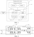
- the charging control system 1 includes a charging control device 10 and a charging device 11.
- the charging control device 10 is connected with the charging device 11.
- the charge control device 10 includes a processor and a memory that are connected with each other.
- the charging device 11 includes an OBC module 110, a DC module 112, a power battery 111, and a storage battery 113.
- One end of the OBC module 110 is externally connected with a charging port, an other end of the OBC module 110 is respectively connected with one end of the power battery 111 and one end of the DC module 112, and an other end of the DC module 112 is connected with the storage battery 113.
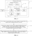
- the OBC module 110 includes a PFC unit 1100, a first capacitor C1, an LLC unit 1101, and a second capacitor C2 connected in sequence.
- the PFC unit 1100 is connected with the charging port, and the second capacitor C2 is respectively connected with a precharge module 120 and the DC module 112.
- the charging control device 10 is a core processing device of the charging control system 1, which is configured to receive parameter information collected by a related component in the charging device 11, perform analysis according to the parameter information, and control switch transistors in the OBC module 110 and the DC module 112 according to an analysis result, so as to realize charging control of the power battery 111 and the storage battery 113. It should be noted that the charging control device 10 in this embodiment may be a controller or a control chip.
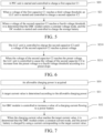
- the charging control system 1 further includes a precharge module 120.
- One end of the precharge module 120 is connected with the power battery 111, and an other end of the precharge module 120 is respectively connected with the OBC module 110 and the DC module 112.
- the precharge module 120 is configured to realize connection/disconnection between the OBC module 110 and the power battery 111, and realize precharging of the power battery 111.
- the precharge module 120 includes a first switch, a second switch, and a precharge resistor.
- the second switch and the precharge resistor are connected in series, and the second switch and the precharge resistor connected in series are connected in parallel with the first switch.
- the above is a hardware environment for implementation of the charging control method of the present disclosure.
- the above hardware environment is not the only way to perform the technical solution of the present disclosure, which may be dynamically adjusted according to a hardware resource and a charging requirement.
- the processor and the memory are integrated into one control chip or one controller to improve the integration level.
- the charging control method of the present disclosure may be implemented based on the above hardware environment.
- the charging control method, the charging control device, and the vehicle provided in the present disclosure are described below with reference to the accompanying drawings.
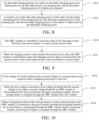
- FIG. 4 is a schematic flowchart of a charging control method according to an embodiment of the present disclosure. As shown in FIG. 4 , the charging control method includes the following steps.
- S1 A first voltage of a power battery and a second voltage of a storage battery are acquired when a charging instruction is received.
- the charging instruction is received.
- a switch module may be arranged between the OBC module and the power battery to realize the disconnection and connection between the OBC module and the power battery.
- the step of charging the storage battery through the OBC module and the DC module in the above embodiment includes: controlling the OBC module to enter a constant voltage mode, and controlling the DC module to charge the storage battery in the constant voltage mode.
- the PFC unit in a process of starting and controlling the PFC unit to charge the first capacitor C1, in order to avoid causing an excessively large instantaneous current flowing through the first capacitor C1 and causing damage to the first capacitor C1 as a result of a charging voltage of the first capacitor C1 increasing too fast, the PFC unit is controlled in the present disclosure, to cause the charging voltage of the first capacitor C1 to increase from a preset voltage to a third voltage threshold according to a preset slope, which avoids a phenomenon of the excessively large instantaneous current, thereby further improving the charging safety.
- the preset voltage in this embodiment may even be 0.
- the step of controlling the LLC unit to charge the second capacitor C2 in the above embodiment includes the following steps.
- S210 The LLC unit is controlled to charge the second capacitor C2 until a voltage of the second capacitor C2 reaches the preset voltage.
- the LLC unit is first controlled to charge the second capacitor C2, to cause the voltage of the second capacitor C2 to quickly reach the preset voltage, thereby improving the charging efficiency.
- a charging voltage of the second capacitor C2 increases from the preset voltage to the fourth voltage threshold according to the preset slope, which avoids the occurrence of the excessively large instantaneous current, thereby further improving the charging safety.
- the LLC unit when the voltage of the first capacitor C1 is stable, the LLC unit is started and controlled to charge the second capacitor C2.
- the DC module is started and controlled to charge the battery. In this way, an excessively high charging voltage of the storage battery is avoided, thereby improving the charging safety of the storage battery.
- the storage battery when the voltages of the power battery and the storage battery are both low, the storage battery is first charged for a preset duration, and then the power battery is charged. Therefore, the storage battery can quickly reach a rated voltage, so as to quickly respond to the power demands of all low-voltage loads, which avoids a failure of some functions of the vehicle or even break-down of the vehicle as a result of a start failure caused by the low-voltage loads due to the insufficient power supply voltage of the storage battery, thereby improving the functional safety of the vehicle control.
- the step of charging the power battery through the OBC module in the above embodiment includes: controlling the OBC module to enter a constant current mode and charging the power battery in the constant current mode.
- the power battery when the power battery is charged, the power battery is charged by using a large current. Therefore, the charging duration is shortened, which not only improves the charging rate, but also satisfies the charging demands of the vehicle owners for fast charging.
- steps of controlling the OBC module to enter a constant current mode and charging the power battery in the constant current mode in the above embodiment are given and include the following step.
- the charging power of the power battery is not only limited by the power battery, but also limited by the charging device, even limited by the charging pile, and the like, which requires comprehensive consideration. Therefore, based on this embodiment, in other embodiments, as shown in FIG. 8 , the step of acquiring the allowable charging power in the above embodiment includes the following steps.
- S301 An allowable charging power of a cable, an allowable charging power of a charging device, an allowable power of a charging pile, and an allowable charging power of a battery are acquired.
- the allowable charging power of the cable is acquired by acquiring a resistance of an AC charging device (for example, a charging gun), and obtaining an allowable current value according to the resistance and a table of preset standards, for example, a table of preset standards specifying that 100 S2 corresponds to 63 A, 220 S2 corresponds to 32 A, 680 S2 corresponds to 16 A, and 1.5 KS2 corresponds to 10 A, and then calculating the allowable charging power Pcc of the cable according to the mains supply voltage and the allowable current value.
- a table of preset standards for example, a table of preset standards specifying that 100 S2 corresponds to 63 A, 220 S2 corresponds to 32 A, 680 S2 corresponds to 16 A, and 1.5 KS2 corresponds to 10 A
- the acquisition of the allowable charging power of the charging device is acquired by acquiring a charging control signal PWM according to requirements of GBT 18487.1-2015, and obtaining a duty cycle D by analyzing the PWM.
- An allowable current is obtained according to the duty cycle and by presetting the standard meter.
- the allowable charging power of the battery is acquired by receiving a BMS message to acquire an allowable charging power Pbms of a battery pack of the vehicle.
- S302 A smallest one of the allowable charging power of the cable, the allowable charging power of the charging device, the allowable power of the charging pile, and the allowable charging power of the battery is determined as the allowable charging power.
- the smallest one of the allowable charging power of the cable, the allowable charging power of the charging device, the allowable charging power of the charging pile, and the allowable charging power of the battery is selected as the allowable charging power, which does not exceed the maximum output power of all devices, thereby further improving the charging safety.
- a target current value is determined according to the allowable charging power.
- the OBC module is controlled to increase a value of a charging current flowing to the power battery.
- the step of controlling the OBC module to increase the value of the charging current flowing to the power battery in the above embodiment includes the following steps.
- S320 The OBC module is controlled to cause the value of the charging current flowing to the power battery to reach a preset current value.
- the OBC module is first controlled to cause the charging current flowing to the power battery quickly to reach the preset current value, thereby improving the charging efficiency.
- the charging current flowing to the power battery increases from the preset current value to the target current value according to the preset slope, which avoids the phenomenon of the excessively large instantaneous current, thereby further improving the charging safety.
- the OBC module is controlled to enter the constant current mode, which not only increases the charging rate of the power battery, but also avoids damage to the power battery and the related charging device due to the excessive increase of the charging current, thereby further improving the charging safety.
- FIG. 10 is a schematic flowchart of a charging control method according to another embodiment of the present disclosure. As shown in FIG. 10 , the charging control method includes the following steps.
- S100 A first voltage of a power battery and a second voltage of a storage battery are acquired when a charging instruction is received.
- Step S100 of this embodiment is the same as step S1 of the above embodiment, and the details are not described herein again.
- the OBC module is disconnected from or connected to the power battery by reusing the existing precharge module, which not only improves the integration level of the charging device, but also reduces the cost without adding a switch module.
- the step of disconnecting the OBC module from the power battery through the precharge module in the above embodiment specifically includes: controlling a first switch and a second switch to be opened to disconnect the OBC module from the power battery.
- the OBC module and the power battery are connected by reusing the precharge module, thereby improving the integration level and reducing the cost.
- the power battery is precharged through the precharge module, to charge the power battery by using a large current when the voltage of the power battery matches the voltage of the second capacitor C2, thereby further improving the charging safety of the power battery.
- the step of connecting the OBC module to the power battery through the precharge module, and precharging the power battery through the OBC module and the precharge module in the above embodiment specifically includes: controlling the second switch to be closed and keeping the first switch opened, to connect the OBC module to the power battery, and precharging the power battery through the OBC module and the precharge resistor.
- the storage battery when the voltages of the power battery and the storage battery are both low, the storage battery is first charged for a preset duration, and then the power battery is charged. Therefore, the storage battery can quickly reach a rated voltage, so as to quickly respond to the power demands of all low-voltage loads, which avoids a failure of some functions of the vehicle or even break-down of the vehicle as a result of a start failure caused by the low-voltage loads due to the insufficient power supply voltage of the storage battery, thereby improving the functional safety of the vehicle control.
- the precharge module is reused to realize the connection or disconnection between the OBC module and the power battery, thereby improving the integration level.
- a second aspect of the present disclosure provides a charging control device for a hybrid electric vehicle, including a processor and a memory.
- the processor is connected with the memory, the memory is configured to store a computer program, and the computer program is adapted to be loaded and executed by the processor to:
- the hybrid electric vehicle further includes a precharge module.
- One end of the precharge module is respectively connected with the OBC module and the DC module, and an other end of the precharge module is connected with the power battery.
- the processor is further configured to disconnect the OBC module from the power battery through the precharge module.
- the processor is further configured to connect the OBC module to the power battery through the precharge module, and precharge the power battery through the OBC module and the precharge module.
- the precharge module includes a first switch, a second switch, and a precharge resistor.
- the second switch and the precharge resistor are connected in series, and the second switch and the precharge resistor connected in series are connected in parallel with the first switch.
- the processor is further configured to control a first switch and a second switch to be opened to disconnect the OBC module from the power battery.
- the processor is further configured to control the second switch to be closed and keep the first switch opened, to connect the OBC module to the power battery, and precharge the power battery through the OBC module and the precharge resistor.
- the processor is further configured to control the OBC module to enter a constant voltage mode, and control the DC module to charge the storage battery in the constant voltage mode.
- the OBC module includes a PFC unit, a first capacitor, an LLC unit, and a second capacitor connected in sequence.
- the PFC unit is connected with the charging port, and the second capacitor is respectively connected with the precharge module and the DC module.
- the processor is further configured to:
- the processor is further configured to: control the LLC unit to charge the second capacitor until the voltage of the second capacitor reaches a preset voltage; and control the LLC unit when the voltage of the second capacitor reaches the preset voltage, to cause the voltage of the second capacitor to increase from the preset voltage to the fourth voltage threshold according to a preset slope.
- the processor is further configured to: control the OBC module to enter a constant current mode and charge the power battery in the constant current mode.
- the processor is further configured to:
- the processor is further configured to:
- the processor is further configured to:
- a third aspect of the present disclosure provides a vehicle, including a charging control device for a hybrid electric vehicle described in the above embodiments.
- orientation or position relationships indicated by the terms such as “center”, “longitudinal”, “transverse”, “length”, “width”, “thickness”, “on”, “below”, “front”, “back”, “left”, “right”, “vertical”, “horizontal”, “top”, “bottom”, “inside”, “outside”, “axial direction”, “radial direction”, and “circumferential direction” are based on orientation or position relationships shown in the accompanying drawings, and are used only for ease and brevity of illustration and description, rather than indicating or implying that the mentioned apparatus or component must have a particular orientation or must be constructed and operated in a particular orientation. Therefore, such terms should not be construed as a limitation on the present disclosure.
- connection may be a fixed connection, a detachable connection, or an integral connection; or the connection may be a direct connection, an indirect connection through an intermediary, or internal communication between two components.
Landscapes
- Engineering & Computer Science (AREA)
- Power Engineering (AREA)
- Transportation (AREA)
- Mechanical Engineering (AREA)
- Life Sciences & Earth Sciences (AREA)
- Sustainable Development (AREA)
- Sustainable Energy (AREA)
- Charge And Discharge Circuits For Batteries Or The Like (AREA)
- Electric Propulsion And Braking For Vehicles (AREA)
- Hybrid Electric Vehicles (AREA)
Abstract
Description
- The present disclosure claims priority to
Chinese Patent Application No. 202011056385.5, filed on September 29, 2020 - The present disclosure belongs to the field of electronic technologies, and more specifically, to a charging control method and device for a hybrid electric vehicle and a vehicle.
- Currently, when a hybrid electric vehicle is charged, it means directly charging a power battery and supplying power to a storage battery by the power battery.
- However, when voltages of the power battery and the storage battery are both low, based on a protection principle that the power battery cannot discharge excessively, a DC module of the hybrid electric vehicle is not started, and the power battery does not supply power to the storage battery. Therefore, the storage battery may not satisfy power demands of most low-voltage loads, which may lead to the failure of some functions of the vehicle, and may even cause the vehicle to break down.
- The present disclosure is intended to resolve at least one of technical problems existing in the related art. A first object of the present disclosure is to provide a charging control method for a hybrid electric vehicle. The method is first charging a storage battery for a preset duration, and then charging a power battery to avoid the failure of a vehicle function and even avoid breakdown of the vehicle.
- A second object of the present disclosure is to provide a charging control device for a hybrid electric vehicle.
- A third object of the present disclosure is to provide a vehicle.
- In order to resolve the above problem, according to the charging control method for a hybrid electric vehicle provided in an embodiment of a first aspect of the present disclosure, the hybrid electric vehicle includes a charging port, an OBC module, a power battery, a DC module, and a storage battery. One end of the OBC module is connected with the charging port. An other end of the OBC module is respectively connected with one end of the power battery and one end of the DC module. An other end of the DC module is connected with the storage battery. The charging control method includes:
- acquiring a first voltage of the power battery and a second voltage of the storage battery when receiving a charging instruction;
- disconnecting the OBC module from the power battery and charging the storage battery through the OBC module and the DC module when the first voltage is less than a first voltage threshold and the second voltage is less than a second voltage threshold; and
- connecting the OBC module to the power battery and charging the power battery through the OBC module when a charging duration of the storage battery reaches a preset duration.
- In order to resolve the above problem, the charging control device for a hybrid electric vehicle provided in an embodiment of a second aspect of the present disclosure includes:
- a processor; and
- a memory, connected with the processor, where the memory is configured to store a computer program; and the computer program is adapted to be loaded and executed by the processor to:
- acquire a first voltage of the power battery and a second voltage of the storage battery when receiving a charging instruction;
- disconnect the OBC module from the power battery and charge the storage battery through the OBC module and the DC module when the first voltage is less than a first voltage threshold and the second voltage is less than a second voltage threshold; and
- connect the OBC module to the power battery and charge the power battery through the OBC module when a charging duration of the storage battery reaches a preset duration.
- In order to resolve the above problem, a vehicle provided in an embodiment of a third aspect of the present disclosure includes the charging control device for a hybrid electric vehicle described above.
- Compared with the related art, according to the present disclosure, when the voltages of the power battery and the storage battery are both low, the storage battery is first charged for a preset duration, and then the power battery is charged. Therefore, the storage battery can quickly reach a rated voltage, so as to quickly respond to the power demands of all low-voltage loads, which avoids a failure of some functions of the vehicle or even break-down of the vehicle as a result of a start failure caused by the low-voltage loads due to the insufficient power supply voltage of the storage battery, thereby improving the functional safety of the vehicle control.
- Additional aspects and advantages of the present disclosure are to be partially given in the following description, and some will become apparent in the following description, or may be learned by practice of the present disclosure.
- The foregoing and/or additional aspects and advantages of the present disclosure will become apparent and easy to understand in the description of the embodiments made with reference to the following accompanying drawings.
-
FIG. 1 is a schematic diagram of a frame structure of a charging control method according to an embodiment of the present disclosure. -
FIG. 2 is a schematic diagram of a topology structure of an OBC module according to an embodiment of the present disclosure. -
FIG. 3 is a schematic diagram of a frame structure of a charging control method according to another embodiment of the present disclosure. -
FIG. 4 is a schematic flowchart of a charging control method according to an embodiment of the present disclosure. -
FIG. 5 is a schematic flowchart of charging in a constant voltage mode in a charging control method according to an embodiment of the present disclosure. -
FIG. 6 is a schematic flowchart of regular boosting in the constant voltage mode inFIG. 5 . -
FIG. 7 is a schematic flowchart of charging in a constant current mode in a charging control method according to an embodiment of the present disclosure. -
FIG. 8 is a schematic flowchart of acquisition of an allowable charging power during charging in the constant current mode inFIG. 7 . -
FIG. 9 is a schematic flowchart of regularly increasing a current during charging in the constant current mode inFIG. 7 . -
FIG. 10 is a schematic flowchart of a charging control method according to another embodiment of the present disclosure. - The embodiments of the present disclosure are described in detail below, and the embodiments described with reference to accompanying drawings are exemplary.
- When a charging control method provided in the present disclosure is applied to charging control of a hybrid electric vehicle, the charging control method provided in the present disclosure may be implemented in a
charging control system 1 shown inFIG. 1 . Thecharging control system 1 includes acharging control device 10 and acharging device 11. Thecharging control device 10 is connected with thecharging device 11. Thecharge control device 10 includes a processor and a memory that are connected with each other. Thecharging device 11 includes an OBCmodule 110, aDC module 112, apower battery 111, and astorage battery 113. One end of the OBCmodule 110 is externally connected with a charging port, an other end of the OBCmodule 110 is respectively connected with one end of thepower battery 111 and one end of theDC module 112, and an other end of theDC module 112 is connected with thestorage battery 113. - Based on this embodiment, in other embodiments, as shown in
FIG. 2 , the OBCmodule 110 includes aPFC unit 1100, a first capacitor C1, anLLC unit 1101, and a second capacitor C2 connected in sequence. ThePFC unit 1100 is connected with the charging port, and the second capacitor C2 is respectively connected with aprecharge module 120 and theDC module 112. - The
charging control device 10 is a core processing device of thecharging control system 1, which is configured to receive parameter information collected by a related component in thecharging device 11, perform analysis according to the parameter information, and control switch transistors in theOBC module 110 and theDC module 112 according to an analysis result, so as to realize charging control of thepower battery 111 and thestorage battery 113. It should be noted that thecharging control device 10 in this embodiment may be a controller or a control chip. - In other embodiments, based on the above embodiments, as shown in
FIG. 3 , thecharging control system 1 further includes aprecharge module 120. One end of theprecharge module 120 is connected with thepower battery 111, and an other end of theprecharge module 120 is respectively connected with the OBCmodule 110 and theDC module 112. Theprecharge module 120 is configured to realize connection/disconnection between the OBCmodule 110 and thepower battery 111, and realize precharging of thepower battery 111. - Based on this embodiment, in other embodiments, the
precharge module 120 includes a first switch, a second switch, and a precharge resistor. The second switch and the precharge resistor are connected in series, and the second switch and the precharge resistor connected in series are connected in parallel with the first switch. - The above is a hardware environment for implementation of the charging control method of the present disclosure. However, it should be noted that the above hardware environment is not the only way to perform the technical solution of the present disclosure, which may be dynamically adjusted according to a hardware resource and a charging requirement. For example, the processor and the memory are integrated into one control chip or one controller to improve the integration level.
- That is to say, the charging control method of the present disclosure may be implemented based on the above hardware environment. The charging control method, the charging control device, and the vehicle provided in the present disclosure are described below with reference to the accompanying drawings.
-
FIG. 4 is a schematic flowchart of a charging control method according to an embodiment of the present disclosure. As shown inFIG. 4 , the charging control method includes the following steps. - S1: A first voltage of a power battery and a second voltage of a storage battery are acquired when a charging instruction is received.
- In this embodiment, when it is detected that a charging gun on a charging pile is inserted into a charging port of a vehicle, the charging instruction is received.
- S2: When the first voltage is less than a first voltage threshold and the second voltage is less than a second voltage threshold, an OBC module is disconnected from the power battery, and the storage battery is charged through the OBC module and a DC module.
- In this embodiment, in a case that the power battery of a hybrid electric vehicle is in a low state of charge, a condition in which voltages of the power battery and the storage battery are both low occurs when the hybrid electric vehicle is parked in a parking lot and is not used for a long time.
- In this embodiment, according to the present disclosure, a switch module may be arranged between the OBC module and the power battery to realize the disconnection and connection between the OBC module and the power battery.
- An electric capacity of the storage battery is much less than an electric capacity of the power battery. Therefore, if a fast charging strategy of the power battery is used for charging the storage battery, the storage battery may be damaged and even the whole charging device may fail because a charging voltage and/or a charging current is excessively large. Therefore, in order to ensure the charging safety of the storage battery, based on the above embodiments, in other embodiments, the step of charging the storage battery through the OBC module and the DC module in the above embodiment includes:
controlling the OBC module to enter a constant voltage mode, and controlling the DC module to charge the storage battery in the constant voltage mode. - Based on the above embodiment, in other embodiments, as shown in
FIG. 5 , specific steps of controlling the OBC module to enter the constant voltage mode and controlling the DC module to charge the storage battery in the constant voltage mode in the above embodiment are given and include the following steps. - S20: The PFC unit is started and controlled to charge the first capacitor C1.
- In this embodiment, in a process of starting and controlling the PFC unit to charge the first capacitor C1, in order to avoid causing an excessively large instantaneous current flowing through the first capacitor C1 and causing damage to the first capacitor C1 as a result of a charging voltage of the first capacitor C1 increasing too fast, the PFC unit is controlled in the present disclosure, to cause the charging voltage of the first capacitor C1 to increase from a preset voltage to a third voltage threshold according to a preset slope, which avoids a phenomenon of the excessively large instantaneous current, thereby further improving the charging safety.
- It should be noted that the preset voltage in this embodiment may even be 0.
- S21: When a voltage of the first capacitor C1 reaches a third voltage threshold, the LLC unit is started and controlled to charge the second capacitor C2.
- In this embodiment, in a process of starting and controlling the LLC unit to charge the second capacitor C2, in order to avoid causing an excessively large instantaneous current flowing through the second capacitor C2 and causing damage to the second capacitor C2 as a result of a charging voltage of the second capacitor C2 increasing excessively fast, based on this embodiment, in other embodiments, as shown in
FIG. 6 , the step of controlling the LLC unit to charge the second capacitor C2 in the above embodiment includes the following steps. - S210: The LLC unit is controlled to charge the second capacitor C2 until a voltage of the second capacitor C2 reaches the preset voltage.
- In this embodiment, the LLC unit is first controlled to charge the second capacitor C2, to cause the voltage of the second capacitor C2 to quickly reach the preset voltage, thereby improving the charging efficiency.
- S211: When the voltage of the second capacitor C2 reaches the preset voltage, the LLC unit is controlled to cause the voltage of the second capacitor C2 to increase from the preset voltage to a fourth voltage threshold according to the preset slope.
- In this embodiment, a charging voltage of the second capacitor C2 increases from the preset voltage to the fourth voltage threshold according to the preset slope, which avoids the occurrence of the excessively large instantaneous current, thereby further improving the charging safety.
- S22: When the voltage of the second capacitor C2 reaches the fourth voltage threshold, it is determined that the OBC module enters the constant voltage mode, and the DC module is started and controlled to charge the storage battery.
- In this embodiment, when the voltage of the first capacitor C1 is stable, the LLC unit is started and controlled to charge the second capacitor C2. When the voltage of the second capacitor C2 is stable, the DC module is started and controlled to charge the battery. In this way, an excessively high charging voltage of the storage battery is avoided, thereby improving the charging safety of the storage battery.
- S3: When a charging duration of the storage battery reaches a preset duration, the OBC module is connected to the power battery, and the power battery is charged through the OBC module.
- In the present disclosure, when the voltages of the power battery and the storage battery are both low, the storage battery is first charged for a preset duration, and then the power battery is charged. Therefore, the storage battery can quickly reach a rated voltage, so as to quickly respond to the power demands of all low-voltage loads, which avoids a failure of some functions of the vehicle or even break-down of the vehicle as a result of a start failure caused by the low-voltage loads due to the insufficient power supply voltage of the storage battery, thereby improving the functional safety of the vehicle control.
- Due to the excessively large electric capacity of the power battery, in order to meet the requirements of most vehicle owners, the charging duration of the power battery needs to be shortened. Therefore, in order to improve the charging rate of the power battery, based on this embodiment, in other embodiments, the step of charging the power battery through the OBC module in the above embodiment includes:
controlling the OBC module to enter a constant current mode and charging the power battery in the constant current mode. - In this embodiment, when the power battery is charged, the power battery is charged by using a large current. Therefore, the charging duration is shortened, which not only improves the charging rate, but also satisfies the charging demands of the vehicle owners for fast charging.
- Based on this embodiment, in other embodiments, as shown in
FIG. 7 , specific steps of controlling the OBC module to enter a constant current mode and charging the power battery in the constant current mode in the above embodiment are given and include the following step. - S30: An allowable charging power is acquired.
- The charging power of the power battery is not only limited by the power battery, but also limited by the charging device, even limited by the charging pile, and the like, which requires comprehensive consideration. Therefore, based on this embodiment, in other embodiments, as shown in
FIG. 8 , the step of acquiring the allowable charging power in the above embodiment includes the following steps. - S301: An allowable charging power of a cable, an allowable charging power of a charging device, an allowable power of a charging pile, and an allowable charging power of a battery are acquired.
- In this implementation, the allowable charging power of the cable is acquired by acquiring a resistance of an AC charging device (for example, a charging gun), and obtaining an allowable current value according to the resistance and a table of preset standards, for example, a table of preset standards specifying that 100 S2 corresponds to 63 A, 220 S2 corresponds to 32 A, 680 S2 corresponds to 16 A, and 1.5 KS2 corresponds to 10 A, and then calculating the allowable charging power Pcc of the cable according to the mains supply voltage and the allowable current value.
- In this implementation, the acquisition of the allowable charging power of the charging device is acquired by acquiring a charging control signal PWM according to requirements of GBT 18487.1-2015, and obtaining a duty cycle D by analyzing the PWM. An allowable current is obtained according to the duty cycle and by presetting the standard meter. For example, charging is not allowed when D < 8%, the allowable current Imax = 6 when 8% ≤ D < 10%, the allowable current Imax = D*100*0.6 when 10% ≤ D < 85%, the allowable current Imax = (D∗100-64)∗2.5 when 85% ≤ D < 90%, and the charging is not allowed when Imax ≤ 63 and 90% ≤ D, and then the Pcp is calculated according to the mains voltage and the allowable current.
- In this implementation, the allowable charging power of the charging pile is acquired by acquiring an AC side grid voltage and an AC side current, that is, a grid current, and calculating a current charging power Pn according to the power P = U*I.
- In this implementation, the allowable charging power of the battery is acquired by receiving a BMS message to acquire an allowable charging power Pbms of a battery pack of the vehicle.
- S302: A smallest one of the allowable charging power of the cable, the allowable charging power of the charging device, the allowable power of the charging pile, and the allowable charging power of the battery is determined as the allowable charging power.
- In this embodiment, the smallest one of the allowable charging power of the cable, the allowable charging power of the charging device, the allowable charging power of the charging pile, and the allowable charging power of the battery is selected as the allowable charging power, which does not exceed the maximum output power of all devices, thereby further improving the charging safety.
- S31: A target current value is determined according to the allowable charging power.
- S32: The OBC module is controlled to increase a value of a charging current flowing to the power battery.
- In this embodiment, in a process of controlling the OBC module to charge the power battery, in order to avoid causing damage to the power battery or even causing damage to the related device due to the charging current of the power battery increasing excessively fast, therefore, based on this embodiment, in other embodiments, as shown in
FIG. 9 , the step of controlling the OBC module to increase the value of the charging current flowing to the power battery in the above embodiment includes the following steps. - S320: The OBC module is controlled to cause the value of the charging current flowing to the power battery to reach a preset current value.
- In this embodiment, the OBC module is first controlled to cause the charging current flowing to the power battery quickly to reach the preset current value, thereby improving the charging efficiency.
- S321: When the charging current value reaches the preset current value, the OBC module is controlled to cause the charging current value to increase from the preset current value to the target current value according to a preset slope.
- In this embodiment, the charging current flowing to the power battery increases from the preset current value to the target current value according to the preset slope, which avoids the phenomenon of the excessively large instantaneous current, thereby further improving the charging safety.
- S33: When the charging current value reaches the target current value, it is determined that the OBC module enters the constant current mode, and the power battery is charged by using a current corresponding to the target current value.
- In this embodiment, the OBC module is controlled to enter the constant current mode, which not only increases the charging rate of the power battery, but also avoids damage to the power battery and the related charging device due to the excessive increase of the charging current, thereby further improving the charging safety.
-
FIG. 10 is a schematic flowchart of a charging control method according to another embodiment of the present disclosure. As shown inFIG. 10 , the charging control method includes the following steps. - S100: A first voltage of a power battery and a second voltage of a storage battery are acquired when a charging instruction is received.
- Step S100 of this embodiment is the same as step S1 of the above embodiment, and the details are not described herein again.
- S101: When the first voltage is less than a first voltage threshold and the second voltage is less than a second voltage threshold, an OBC module is disconnected from the power battery through a precharge module, and the storage battery is charged through the OBC module and a DC module.
- In this embodiment, the OBC module is disconnected from or connected to the power battery by reusing the existing precharge module, which not only improves the integration level of the charging device, but also reduces the cost without adding a switch module.
- Based on the above embodiments, in other embodiments, the step of disconnecting the OBC module from the power battery through the precharge module in the above embodiment specifically includes:
controlling a first switch and a second switch to be opened to disconnect the OBC module from the power battery. - S102: When a charging duration of the storage battery reaches a preset duration, the OBC module is connected to the power battery through the precharge module, the power battery is precharged through the OBC module and the precharge module, and the power battery is charged through the OBC module.
- In this embodiment, the OBC module and the power battery are connected by reusing the precharge module, thereby improving the integration level and reducing the cost. In addition, before the power battery is charged, the power battery is precharged through the precharge module, to charge the power battery by using a large current when the voltage of the power battery matches the voltage of the second capacitor C2, thereby further improving the charging safety of the power battery.
- Based on the above embodiments, in other embodiments, the step of connecting the OBC module to the power battery through the precharge module, and precharging the power battery through the OBC module and the precharge module in the above embodiment specifically includes:
controlling the second switch to be closed and keeping the first switch opened, to connect the OBC module to the power battery, and precharging the power battery through the OBC module and the precharge resistor. - In the present disclosure, when the voltages of the power battery and the storage battery are both low, the storage battery is first charged for a preset duration, and then the power battery is charged. Therefore, the storage battery can quickly reach a rated voltage, so as to quickly respond to the power demands of all low-voltage loads, which avoids a failure of some functions of the vehicle or even break-down of the vehicle as a result of a start failure caused by the low-voltage loads due to the insufficient power supply voltage of the storage battery, thereby improving the functional safety of the vehicle control. In addition, in this embodiment, the precharge module is reused to realize the connection or disconnection between the OBC module and the power battery, thereby improving the integration level.
- A second aspect of the present disclosure provides a charging control device for a hybrid electric vehicle, including a processor and a memory. The processor is connected with the memory, the memory is configured to store a computer program, and the computer program is adapted to be loaded and executed by the processor to:
- acquire a first voltage of a power battery and a second voltage of a storage battery when receiving a charging instruction;
- disconnect an OBC module from the power battery and charge the storage battery through the OBC module and a DC module when the first voltage is less than a first voltage threshold and the second voltage is less than a second voltage threshold; and
- connect the OBC module to the power battery and charge the power battery through the OBC module when a charging duration of the storage battery reaches a preset duration.
- Optionally, the hybrid electric vehicle further includes a precharge module. One end of the precharge module is respectively connected with the OBC module and the DC module, and an other end of the precharge module is connected with the power battery.
- The processor is further configured to disconnect the OBC module from the power battery through the precharge module.
- The processor is further configured to connect the OBC module to the power battery through the precharge module, and precharge the power battery through the OBC module and the precharge module.
- Optionally, the precharge module includes a first switch, a second switch, and a precharge resistor. The second switch and the precharge resistor are connected in series, and the second switch and the precharge resistor connected in series are connected in parallel with the first switch.
- The processor is further configured to control a first switch and a second switch to be opened to disconnect the OBC module from the power battery.
- The processor is further configured to control the second switch to be closed and keep the first switch opened, to connect the OBC module to the power battery, and precharge the power battery through the OBC module and the precharge resistor.
- Optionally, the processor is further configured to control the OBC module to enter a constant voltage mode, and control the DC module to charge the storage battery in the constant voltage mode.
- Optionally, the OBC module includes a PFC unit, a first capacitor, an LLC unit, and a second capacitor connected in sequence. The PFC unit is connected with the charging port, and the second capacitor is respectively connected with the precharge module and the DC module.
- The processor is further configured to:
- start and control the PFC unit to charge the first capacitor;
- start and control the LLC unit when a voltage of the first capacitor reaches a third voltage threshold, to charge the second capacitor; and
- determine that the OBC module enters the constant voltage mode, and start and control the DC module to charge the storage battery when a voltage of the second capacitor reaches a fourth voltage threshold.
- Optionally, the processor is further configured to: control the LLC unit to charge the second capacitor until the voltage of the second capacitor reaches a preset voltage; and
control the LLC unit when the voltage of the second capacitor reaches the preset voltage, to cause the voltage of the second capacitor to increase from the preset voltage to the fourth voltage threshold according to a preset slope. - Optionally, the processor is further configured to:
control the OBC module to enter a constant current mode and charge the power battery in the constant current mode. - Optionally, the processor is further configured to:
- acquire an allowable charging power;
- determine a target current value according to the allowable charging power;
- control the OBC module to increase a value of a charging current flowing to the power battery; and
- determine that the OBC module enters the constant current mode and charge the power battery by using a current corresponding to the target current value when the charging current value reaches the target current value.
- Optionally, the processor is further configured to:
- acquire an allowable charging power of a cable, an allowable charging power of a charging device, an allowable power of a charging pile, and an allowable charging power of a battery; and
- determine a smallest one of the allowable charging power of the cable, the allowable charging power of the charging device, the allowable power of the charging pile, and the allowable charging power of the battery as the allowable charging power.
- Optionally, the processor is further configured to:
- control the OBC module, to cause the value of the charging current flowing to the power battery to reach a preset current value; and
- control the OBC module when the charging current value reaches the preset current value, to cause the charging current value to increase from the preset current value to the target current value according to a preset slope.
- The specific principles and implementations of the charging control device provided in the embodiment of the present disclosure are similar to those in the above embodiments, and the details are not described herein again.
- A third aspect of the present disclosure provides a vehicle, including a charging control device for a hybrid electric vehicle described in the above embodiments.
- The specific principles and implementations of the charging control device provided in the embodiment of the present disclosure are similar to those in the above embodiments, and the details are not described herein again.
- In the description of the present disclosure, it should be understood that orientation or position relationships indicated by the terms such as "center", "longitudinal", "transverse", "length", "width", "thickness", "on", "below", "front", "back", "left", "right", "vertical", "horizontal", "top", "bottom", "inside", "outside", "axial direction", "radial direction", and "circumferential direction" are based on orientation or position relationships shown in the accompanying drawings, and are used only for ease and brevity of illustration and description, rather than indicating or implying that the mentioned apparatus or component must have a particular orientation or must be constructed and operated in a particular orientation. Therefore, such terms should not be construed as a limitation on the present disclosure.
- In the description of the present disclosure, it should be noted that, unless otherwise explicitly specified or defined, the terms such as "mount", "connect", and "connection" should be understood in a broad sense. For example, the connection may be a fixed connection, a detachable connection, or an integral connection; or the connection may be a direct connection, an indirect connection through an intermediary, or internal communication between two components. A person of ordinary skill in the art may understand the specific meanings of the foregoing terms in the present disclosure according to specific situations.
- In the descriptions of this specification, the description of reference terms such as "one embodiment", "some embodiments", "an exemplary embodiment", "an example", "a specific example", or "some examples" means that specific features, structures, materials, or characteristics described in combination with the embodiment or examples are included in at least one embodiment or example of the present disclosure. In this specification, schematic descriptions of the foregoing terms do not necessarily mean the same embodiment or example.
- Although the embodiments of the present disclosure have been shown and described, a person of ordinary skill in the art should understand that various changes, modifications, replacements, and variations may be made to the embodiments without departing from the principle and spirit of the present disclosure, and the scope of the present disclosure is defined by the claims and their equivalents.
Claims (12)
- A charging control method for a hybrid electric vehicle, wherein the hybrid electric vehicle comprises a charging port, an OBC module, a power battery, a DC module, and a storage battery; one end of the OBC module is connected with the charging port; an other end of the OBC module is respectively connected with one end of the power battery and one end of the DC module; an other end of the DC module is connected with the storage battery; and the charging control method comprises:acquiring a first voltage of the power battery and a second voltage of the storage battery when receiving a charging instruction;disconnecting the OBC module from the power battery and charging the storage battery through the OBC module and the DC module when the first voltage is less than a first voltage threshold and the second voltage is less than a second voltage threshold; andconnecting the OBC module to the power battery and charging the power battery through the OBC module when a charging duration of the storage battery reaches a preset duration.
- The charging control method for a hybrid electric vehicle according to claim 1, wherein the hybrid electric vehicle further comprises a precharge module; one end of the precharge module is respectively connected with the OBC module and the DC module; an other end of the precharge module is connected with the power battery;
the step of the disconnecting the OBC module from the power battery comprises:disconnecting the OBC module from the power battery through the precharge module; andthe step of connecting the OBC module to the power battery comprises:
connecting the OBC module to the power battery through the precharge module, and precharging the power battery through the OBC module and the precharge module. - The charging control method for a hybrid electric vehicle according to claim 2, wherein the precharge module comprises a first switch, a second switch, and a precharge resistor; the second switch and the precharge resistor are connected in series; the second switch and the precharge resistor connected in series are connected in parallel with the first switch;
the step of disconnecting the OBC module from the power battery through the precharge module comprises:controlling the first switch and the second switch to be opened, to disconnect the OBC module from the power battery; andthe step of connecting the OBC module to the power battery through the precharge module, and precharging the power battery through the OBC module and the precharge module comprises:
controlling the second switch to be closed and keeping the first switch opened, to connect the OBC module to the power battery, and precharging the power battery through the OBC module and the precharge resistor. - The charging control method for a hybrid electric vehicle according to claim 2, wherein the step of charging the storage battery through the OBC module and the DC module comprises:
controlling the OBC module to enter a constant voltage mode, and controlling the DC module to charge the storage battery in the constant voltage mode. - The charging control method for a hybrid electric vehicle according to claim 4, wherein the OBC module comprises a PFC unit, a first capacitor, an LLC unit, and a second capacitor connected in sequence; the PFC unit is connected with the charging port; the second capacitor is respectively connected with the precharge module and the DC module; and
the step of controlling the OBC module to enter the constant voltage mode, and controlling the DC module to charge the storage battery in the constant voltage mode comprises:starting and controlling the PFC unit to charge the first capacitor;starting and controlling the LLC unit when a voltage of the first capacitor reaches a third voltage threshold, to charge the second capacitor; anddetermining that the OBC module enters the constant voltage mode and starting and controlling the DC module to charge the storage battery when a voltage of the second capacitor reaches a fourth voltage threshold. - The charging control method for a hybrid electric vehicle according to claim 5, wherein the step of controlling the LLC unit to charge the second capacitor comprises:controlling the LLC unit to charge the second capacitor until the voltage of the second capacitor reaches a preset voltage; andcontrolling the LLC unit when the voltage of the second capacitor reaches the preset voltage, to cause the voltage of the second capacitor to increase from the preset voltage to the fourth voltage threshold according to a preset slope.
- The charging control method for a hybrid electric vehicle according to claim 1, wherein the step of charging the power battery through the OBC module comprises:
controlling the OBC module to enter a constant current mode and charging the power battery in the constant current mode. - The charging control method for a hybrid electric vehicle according to claim 7, wherein
the step of controlling the OBC module to enter the constant current mode and charging the power battery in the constant current mode comprises:acquiring an allowable charging power;determining a target current value according to the allowable charging power;controlling the OBC module to increase a value of a charging current flowing to the power battery; anddetermining that the OBC module enters the constant current mode and charging the power battery by using a current corresponding to the target current value when the charging current value reaches the target current value. - The charging control method for a hybrid electric vehicle according to claim 8, wherein the step of acquiring the allowable charging power comprises:acquiring an allowable charging power of a cable, an allowable charging power of a charging device, an allowable power of a charging pile, and an allowable charging power of a battery; anddetermining a smallest one of the allowable charging power of the cable, the allowable charging power of the charging device, the allowable power of the charging pile, and the allowable charging power of the battery as the allowable charging power.
- The charging control method for a hybrid electric vehicle according to claim 8, wherein the step of controlling the OBC module to increase the value of the charging current flowing to the power battery comprises:controlling the OBC module, to cause the value of the charging current flowing to the power battery to reach a preset current value; andcontrolling the OBC module when the charging current value reaches the preset current value, to cause the charging current value to increase from the preset current value to the target current value according to a preset slope.
- A charging control device for a hybrid electric vehicle, comprising:a processor; anda memory, connected with the processor, wherein the memory is configured to store a computer program; and the computer program is adapted to be loaded and executed by the processor to:acquire a first voltage of a power battery and a second voltage of a storage battery when receiving a charging instruction;disconnect an OBC module from the power battery and charge the storage battery through the OBC module and a DC module when the first voltage is less than a first voltage threshold and the second voltage is less than a second voltage threshold; andconnect the OBC module to the power battery and charge the power battery through the OBC module when a charging duration of the storage battery reaches a preset duration.
- A vehicle, comprising the charging control device for a hybrid electric vehicle according to claim 10.
Applications Claiming Priority (2)
| Application Number | Priority Date | Filing Date | Title |
|---|---|---|---|
| CN202011056385.5A CN114336801A (en) | 2020-09-29 | 2020-09-29 | Charging control method and device for hybrid electric vehicle and vehicle |
| PCT/CN2021/118564 WO2022068593A1 (en) | 2020-09-29 | 2021-09-15 | Charging control method and apparatus for hybrid electric vehicle, and vehicle |
Publications (2)
| Publication Number | Publication Date |
|---|---|
| EP4207538A1 true EP4207538A1 (en) | 2023-07-05 |
| EP4207538A4 EP4207538A4 (en) | 2024-04-10 |
Family
ID=80949574
Family Applications (1)
| Application Number | Title | Priority Date | Filing Date |
|---|---|---|---|
| EP21874254.2A Pending EP4207538A4 (en) | 2020-09-29 | 2021-09-15 | CHARGING CONTROL METHOD AND APPARATUS FOR A HYBRID ELECTRIC VEHICLE AND VEHICLE |
Country Status (5)
| Country | Link |
|---|---|
| US (1) | US20230226933A1 (en) |
| EP (1) | EP4207538A4 (en) |
| JP (1) | JP7469563B2 (en) |
| CN (1) | CN114336801A (en) |
| WO (1) | WO2022068593A1 (en) |
Families Citing this family (9)
| Publication number | Priority date | Publication date | Assignee | Title |
|---|---|---|---|---|
| CN115771415B (en) * | 2021-09-07 | 2025-06-20 | 通用汽车环球科技运作有限责任公司 | Controlling DC-DC converter for DC charging |
| US20250364824A1 (en) * | 2022-06-01 | 2025-11-27 | Milwaukee Electric Tool Corporation | Hybrid supercapacitors in power tool devices |
| CN114851912A (en) * | 2022-06-02 | 2022-08-05 | 广汽埃安新能源汽车有限公司 | Control method and device for charging current of automobile battery and electronic equipment |
| CN115285048B (en) * | 2022-09-13 | 2023-09-05 | 中通客车股份有限公司 | Control system and control method for charging storage battery and unmanned vehicle |
| CN116394797A (en) * | 2023-04-06 | 2023-07-07 | 岚图汽车科技有限公司 | An electric vehicle high-voltage platform charging system and method |
| US20250010738A1 (en) * | 2023-07-04 | 2025-01-09 | Morgan D. Rosenberg | Electric vehicle with fast charging system |
| CN117104076A (en) * | 2023-07-26 | 2023-11-24 | 珠海格力电器股份有限公司 | Control method, device, pure electric bus and storage medium for pure electric bus |
| DE102024203072B3 (en) * | 2024-04-03 | 2025-07-24 | Volkswagen Aktiengesellschaft | motor vehicle |
| CN118322940B (en) * | 2024-05-16 | 2025-01-21 | 陕西融和绿动汽车科技有限公司 | A new energy vehicle battery charging method and system |
Family Cites Families (16)
| Publication number | Priority date | Publication date | Assignee | Title |
|---|---|---|---|---|
| JP2010213499A (en) * | 2009-03-11 | 2010-09-24 | Omron Corp | Charge controller and method, charger, and program |
| JP2010263683A (en) * | 2009-05-01 | 2010-11-18 | Panasonic Corp | Charger |
| JP5402457B2 (en) * | 2009-09-24 | 2014-01-29 | トヨタ自動車株式会社 | Vehicle power system |
| JP5293841B2 (en) * | 2010-02-09 | 2013-09-18 | トヨタ自動車株式会社 | Electric vehicle power supply system and control method thereof |
| KR101305605B1 (en) * | 2011-11-25 | 2013-09-09 | 엘에스산전 주식회사 | Electric Vehicle Power Supply System |
| JP5901383B2 (en) * | 2012-03-27 | 2016-04-06 | 本田技研工業株式会社 | In-vehicle charging system |
| JP6185246B2 (en) * | 2013-01-10 | 2017-08-23 | 新電元工業株式会社 | Switching power supply |
| CN104852418B (en) * | 2014-12-19 | 2017-12-08 | 北汽福田汽车股份有限公司 | It is a kind of to prevent from crossing the method and system put when battery charges |
| CN106340916A (en) * | 2016-09-05 | 2017-01-18 | 北京新能源汽车股份有限公司 | Automobile charging method, charging device, charging system and automobile |
| US10457155B2 (en) * | 2016-09-09 | 2019-10-29 | Ford Global Technologies, Llc | System and method for charging electrified vehicle low-voltage battery |
| CN107089166A (en) * | 2017-05-19 | 2017-08-25 | 北京新能源汽车股份有限公司 | Charging method and system for electric vehicle |
| CN107994631A (en) * | 2017-11-30 | 2018-05-04 | 北京新能源汽车股份有限公司 | Emergency power-on circuit and method and automobile |
| US10351004B1 (en) * | 2018-01-03 | 2019-07-16 | Lear Corporation | Pre-charging DC link capacitor of on-board charger (OBC) using traction battery |
| CN111371160B (en) * | 2018-12-25 | 2022-05-13 | 比亚迪股份有限公司 | Electric vehicle, in-vehicle integrated device, and control method of in-vehicle integrated device |
| CN111376757B (en) * | 2018-12-29 | 2022-05-13 | 比亚迪股份有限公司 | Vehicle, vehicle-mounted charger and control method thereof |
| JP7120072B2 (en) * | 2019-02-22 | 2022-08-17 | 株式会社デンソー | Precharge controller |
-
2020
- 2020-09-29 CN CN202011056385.5A patent/CN114336801A/en active Pending
-
2021
- 2021-09-15 JP JP2023519631A patent/JP7469563B2/en active Active
- 2021-09-15 EP EP21874254.2A patent/EP4207538A4/en active Pending
- 2021-09-15 WO PCT/CN2021/118564 patent/WO2022068593A1/en not_active Ceased
-
2023
- 2023-03-15 US US18/121,943 patent/US20230226933A1/en active Pending
Also Published As
| Publication number | Publication date |
|---|---|
| JP2023543076A (en) | 2023-10-12 |
| JP7469563B2 (en) | 2024-04-16 |
| EP4207538A4 (en) | 2024-04-10 |
| CN114336801A (en) | 2022-04-12 |
| US20230226933A1 (en) | 2023-07-20 |
| WO2022068593A1 (en) | 2022-04-07 |
Similar Documents
| Publication | Publication Date | Title |
|---|---|---|
| US20230226933A1 (en) | Charging control method and device for hybrid electric vehicle and vehicle | |
| CN113581006B (en) | Boost charging method and device and electric automobile | |
| EP2994989B1 (en) | Pre-charging and voltage supply system for a dc-ac inverter | |
| CN114889473A (en) | Electric automobile direct-current boost charging control system, control method and vehicle | |
| US8738954B2 (en) | Power source circuit and control method thereof | |
| US20240116387A1 (en) | Vehicle and charging method therefor and storage medium | |
| CN107894567A (en) | The detecting system and detection method of battery bag and battery bag Interface status | |
| CN112165156A (en) | Charging/discharging device, battery system, charging/discharging control method, and storage medium | |
| CN110661309A (en) | External charging method and device for vehicle | |
| CN116923122B (en) | Charging control methods, devices, equipment and storage media | |
| EP4297232A1 (en) | Energy system, and charging and discharging control method | |
| CN116008749A (en) | Vehicle and its insulation fault position detection method, device, storage medium and system | |
| WO2024077422A1 (en) | Charging control method and apparatus, device, computer-readable storage medium, and program | |
| CN114649859B (en) | Expandable energy storage system and expansion method thereof | |
| CN209955776U (en) | Battery charging device | |
| KR101794101B1 (en) | Apparatus for controlling charging and method thereof | |
| EP4545338A1 (en) | A method for interfacing an auxiliary electrical system with an electrical power network of a vehicle | |
| CN118528846A (en) | A discharge and pre-charging device and control method for a low-power DC charger | |
| EP3258567A1 (en) | Self-loop detection method and apparatus for charging device | |
| CN116846016A (en) | Overvoltage protection methods, energy storage equipment and battery packs | |
| CN103532212A (en) | Charging management circuit and movable power supply | |
| CN209795211U (en) | charger control system | |
| CN116569440A (en) | Battery management method and device, storage medium, electronic equipment, and vehicle | |
| CN111384736B (en) | Charging/discharging device, control method and device, battery device, and storage medium | |
| KR20220020739A (en) | Apparatus for controlling charging of electric vehicle and method thereof |
Legal Events
| Date | Code | Title | Description |
|---|---|---|---|
| STAA | Information on the status of an ep patent application or granted ep patent |
Free format text: STATUS: THE INTERNATIONAL PUBLICATION HAS BEEN MADE |
|
| PUAI | Public reference made under article 153(3) epc to a published international application that has entered the european phase |
Free format text: ORIGINAL CODE: 0009012 |
|
| STAA | Information on the status of an ep patent application or granted ep patent |
Free format text: STATUS: REQUEST FOR EXAMINATION WAS MADE |
|
| 17P | Request for examination filed |
Effective date: 20230329 |
|
| AK | Designated contracting states |
Kind code of ref document: A1 Designated state(s): AL AT BE BG CH CY CZ DE DK EE ES FI FR GB GR HR HU IE IS IT LI LT LU LV MC MK MT NL NO PL PT RO RS SE SI SK SM TR |
|
| DAV | Request for validation of the european patent (deleted) | ||
| DAX | Request for extension of the european patent (deleted) | ||
| A4 | Supplementary search report drawn up and despatched |
Effective date: 20240314 |
|
| RIC1 | Information provided on ipc code assigned before grant |
Ipc: B60L 58/20 20190101ALI20240307BHEP Ipc: B60L 53/20 20190101ALI20240307BHEP Ipc: H02J 7/00 20060101AFI20240307BHEP |