EP4207475A1 - Battery module, battery pack, and electronic device - Google Patents
Battery module, battery pack, and electronic device Download PDFInfo
- Publication number
- EP4207475A1 EP4207475A1 EP20955718.0A EP20955718A EP4207475A1 EP 4207475 A1 EP4207475 A1 EP 4207475A1 EP 20955718 A EP20955718 A EP 20955718A EP 4207475 A1 EP4207475 A1 EP 4207475A1
- Authority
- EP
- European Patent Office
- Prior art keywords
- battery
- battery cell
- circuit board
- tab
- disposed
- Prior art date
- Legal status (The legal status is an assumption and is not a legal conclusion. Google has not performed a legal analysis and makes no representation as to the accuracy of the status listed.)
- Granted
Links
Images




Classifications
-
- H—ELECTRICITY
- H01—ELECTRIC ELEMENTS
- H01M—PROCESSES OR MEANS, e.g. BATTERIES, FOR THE DIRECT CONVERSION OF CHEMICAL ENERGY INTO ELECTRICAL ENERGY
- H01M50/00—Constructional details or processes of manufacture of the non-active parts of electrochemical cells other than fuel cells, e.g. hybrid cells
- H01M50/50—Current conducting connections for cells or batteries
- H01M50/502—Interconnectors for connecting terminals of adjacent batteries; Interconnectors for connecting cells outside a battery casing
- H01M50/519—Interconnectors for connecting terminals of adjacent batteries; Interconnectors for connecting cells outside a battery casing comprising printed circuit boards [PCB]
-
- H—ELECTRICITY
- H01—ELECTRIC ELEMENTS
- H01M—PROCESSES OR MEANS, e.g. BATTERIES, FOR THE DIRECT CONVERSION OF CHEMICAL ENERGY INTO ELECTRICAL ENERGY
- H01M10/00—Secondary cells; Manufacture thereof
- H01M10/42—Methods or arrangements for servicing or maintenance of secondary cells or secondary half-cells
-
- H—ELECTRICITY
- H01—ELECTRIC ELEMENTS
- H01M—PROCESSES OR MEANS, e.g. BATTERIES, FOR THE DIRECT CONVERSION OF CHEMICAL ENERGY INTO ELECTRICAL ENERGY
- H01M10/00—Secondary cells; Manufacture thereof
- H01M10/42—Methods or arrangements for servicing or maintenance of secondary cells or secondary half-cells
- H01M10/425—Structural combination with electronic components, e.g. electronic circuits integrated to the outside of the casing
-
- H—ELECTRICITY
- H01—ELECTRIC ELEMENTS
- H01M—PROCESSES OR MEANS, e.g. BATTERIES, FOR THE DIRECT CONVERSION OF CHEMICAL ENERGY INTO ELECTRICAL ENERGY
- H01M50/00—Constructional details or processes of manufacture of the non-active parts of electrochemical cells other than fuel cells, e.g. hybrid cells
- H01M50/10—Primary casings; Jackets or wrappings
- H01M50/102—Primary casings; Jackets or wrappings characterised by their shape or physical structure
- H01M50/103—Primary casings; Jackets or wrappings characterised by their shape or physical structure prismatic or rectangular
-
- H—ELECTRICITY
- H01—ELECTRIC ELEMENTS
- H01M—PROCESSES OR MEANS, e.g. BATTERIES, FOR THE DIRECT CONVERSION OF CHEMICAL ENERGY INTO ELECTRICAL ENERGY
- H01M50/00—Constructional details or processes of manufacture of the non-active parts of electrochemical cells other than fuel cells, e.g. hybrid cells
- H01M50/20—Mountings; Secondary casings or frames; Racks, modules or packs; Suspension devices; Shock absorbers; Transport or carrying devices; Holders
- H01M50/204—Racks, modules or packs for multiple batteries or multiple cells
- H01M50/207—Racks, modules or packs for multiple batteries or multiple cells characterised by their shape
- H01M50/209—Racks, modules or packs for multiple batteries or multiple cells characterised by their shape adapted for prismatic or rectangular cells
-
- H—ELECTRICITY
- H01—ELECTRIC ELEMENTS
- H01M—PROCESSES OR MEANS, e.g. BATTERIES, FOR THE DIRECT CONVERSION OF CHEMICAL ENERGY INTO ELECTRICAL ENERGY
- H01M50/00—Constructional details or processes of manufacture of the non-active parts of electrochemical cells other than fuel cells, e.g. hybrid cells
- H01M50/20—Mountings; Secondary casings or frames; Racks, modules or packs; Suspension devices; Shock absorbers; Transport or carrying devices; Holders
- H01M50/204—Racks, modules or packs for multiple batteries or multiple cells
- H01M50/207—Racks, modules or packs for multiple batteries or multiple cells characterised by their shape
- H01M50/211—Racks, modules or packs for multiple batteries or multiple cells characterised by their shape adapted for pouch cells
-
- H—ELECTRICITY
- H01—ELECTRIC ELEMENTS
- H01M—PROCESSES OR MEANS, e.g. BATTERIES, FOR THE DIRECT CONVERSION OF CHEMICAL ENERGY INTO ELECTRICAL ENERGY
- H01M50/00—Constructional details or processes of manufacture of the non-active parts of electrochemical cells other than fuel cells, e.g. hybrid cells
- H01M50/20—Mountings; Secondary casings or frames; Racks, modules or packs; Suspension devices; Shock absorbers; Transport or carrying devices; Holders
- H01M50/271—Lids or covers for the racks or secondary casings
-
- H—ELECTRICITY
- H01—ELECTRIC ELEMENTS
- H01M—PROCESSES OR MEANS, e.g. BATTERIES, FOR THE DIRECT CONVERSION OF CHEMICAL ENERGY INTO ELECTRICAL ENERGY
- H01M50/00—Constructional details or processes of manufacture of the non-active parts of electrochemical cells other than fuel cells, e.g. hybrid cells
- H01M50/20—Mountings; Secondary casings or frames; Racks, modules or packs; Suspension devices; Shock absorbers; Transport or carrying devices; Holders
- H01M50/284—Mountings; Secondary casings or frames; Racks, modules or packs; Suspension devices; Shock absorbers; Transport or carrying devices; Holders with incorporated circuit boards, e.g. printed circuit boards [PCB]
-
- H—ELECTRICITY
- H01—ELECTRIC ELEMENTS
- H01M—PROCESSES OR MEANS, e.g. BATTERIES, FOR THE DIRECT CONVERSION OF CHEMICAL ENERGY INTO ELECTRICAL ENERGY
- H01M50/00—Constructional details or processes of manufacture of the non-active parts of electrochemical cells other than fuel cells, e.g. hybrid cells
- H01M50/50—Current conducting connections for cells or batteries
-
- H—ELECTRICITY
- H01—ELECTRIC ELEMENTS
- H01M—PROCESSES OR MEANS, e.g. BATTERIES, FOR THE DIRECT CONVERSION OF CHEMICAL ENERGY INTO ELECTRICAL ENERGY
- H01M50/00—Constructional details or processes of manufacture of the non-active parts of electrochemical cells other than fuel cells, e.g. hybrid cells
- H01M50/50—Current conducting connections for cells or batteries
- H01M50/502—Interconnectors for connecting terminals of adjacent batteries; Interconnectors for connecting cells outside a battery casing
- H01M50/514—Methods for interconnecting adjacent batteries or cells
- H01M50/516—Methods for interconnecting adjacent batteries or cells by welding, soldering or brazing
-
- H—ELECTRICITY
- H01—ELECTRIC ELEMENTS
- H01M—PROCESSES OR MEANS, e.g. BATTERIES, FOR THE DIRECT CONVERSION OF CHEMICAL ENERGY INTO ELECTRICAL ENERGY
- H01M50/00—Constructional details or processes of manufacture of the non-active parts of electrochemical cells other than fuel cells, e.g. hybrid cells
- H01M50/50—Current conducting connections for cells or batteries
- H01M50/531—Electrode connections inside a battery casing
- H01M50/533—Electrode connections inside a battery casing characterised by the shape of the leads or tabs
-
- H—ELECTRICITY
- H01—ELECTRIC ELEMENTS
- H01M—PROCESSES OR MEANS, e.g. BATTERIES, FOR THE DIRECT CONVERSION OF CHEMICAL ENERGY INTO ELECTRICAL ENERGY
- H01M2220/00—Batteries for particular applications
- H01M2220/20—Batteries in motive systems, e.g. vehicle, ship, plane
-
- H—ELECTRICITY
- H01—ELECTRIC ELEMENTS
- H01M—PROCESSES OR MEANS, e.g. BATTERIES, FOR THE DIRECT CONVERSION OF CHEMICAL ENERGY INTO ELECTRICAL ENERGY
- H01M2220/00—Batteries for particular applications
- H01M2220/30—Batteries in portable systems, e.g. mobile phone, laptop
-
- Y—GENERAL TAGGING OF NEW TECHNOLOGICAL DEVELOPMENTS; GENERAL TAGGING OF CROSS-SECTIONAL TECHNOLOGIES SPANNING OVER SEVERAL SECTIONS OF THE IPC; TECHNICAL SUBJECTS COVERED BY FORMER USPC CROSS-REFERENCE ART COLLECTIONS [XRACs] AND DIGESTS
- Y02—TECHNOLOGIES OR APPLICATIONS FOR MITIGATION OR ADAPTATION AGAINST CLIMATE CHANGE
- Y02E—REDUCTION OF GREENHOUSE GAS [GHG] EMISSIONS, RELATED TO ENERGY GENERATION, TRANSMISSION OR DISTRIBUTION
- Y02E60/00—Enabling technologies; Technologies with a potential or indirect contribution to GHG emissions mitigation
- Y02E60/10—Energy storage using batteries
Definitions
- This application relates to the field of batteries, and in particular, to a battery module, a battery pack containing the battery module, and an electronic device.
- this application provides a battery module and a battery containing the battery module.
- the first battery cell tilts against the second battery cell.
- the first circuit board is disposed between the first battery cell and the second battery cell.
- the first circuit board is inclined with respect to the first battery cell, and the first circuit board is inclined with respect to the second battery cell.
- the space inside a battery is sufficiently utilized by disposing the first circuit board in the space between the first battery cell and the second battery cell, thereby effectively improving an energy density.
- the battery module includes a cell assembly and a first circuit board.
- the cell assembly includes a plurality of battery cells.
- the plurality of battery cells are connected to the first circuit board.
- the plurality of battery cells include a first battery cell and a second battery cell, and the first battery cell is inclined with respect to the second battery cell.
- the first circuit board is disposed between the first battery cell and the second battery cell, the first circuit board is inclined with respect to the first battery cell, and the first circuit board is inclined with respect to the second battery cell.
- each battery cell includes a housing and an electrode assembly accommodated in the housing, and the electrode assembly includes a tab.
- the housing includes a first main plane and a second main plane disposed opposite to each other along a thickness direction of the battery cell.
- a seal edge is disposed at one end of the housing along a length direction of the battery cell.
- the tab extends out of the housing from the seal edge.
- the first battery cell includes a first tab.
- the second battery cell includes a second tab.
- the first tab is opposite to the second tab.
- the housing further includes a first surface connects the seal edge and the first main plane.
- a second surface connects the seal edge and the second main plane.
- a width of the first surface is greater than a width of the second surface along the thickness direction.
- One end of the first circuit board tilts closer to the first surface of the first battery cell, and an opposite end of the first circuit board tilts closer to the first surface of the second battery cell.
- the first circuit board is disposed between the first tab and the second tab.
- the first tab includes a first soldering portion
- the second tab includes a second soldering portion.
- the battery module includes a first connecting strip and a second connecting strip.
- the first connecting strip includes a first fixing portion and a first connecting portion.
- the first fixing portion is soldered to the first circuit board.
- the first connecting portion is welded to the first soldering portion.
- the first soldering portion is disposed between the first fixing portion and the first connecting portion.
- the second connecting strip includes a second fixing portion and a second connecting portion.
- the second fixing portion is soldered to the first circuit board.
- the second connecting portion is welded to the second soldering portion.
- the second soldering portion is disposed between the second fixing portion and the second connecting portion.
- the first fixing portion and the first connecting portion clamp the first soldering portion.
- One surface of the first soldering portion is in contact with the first connecting portion, and an opposite surface of the first soldering portion is in contact with the first fixing portion.
- the second fixing portion and the second connecting portion clamp the second soldering portion.
- One surface of the second soldering portion is in contact with the second connecting portion, and an opposite surface of the second soldering portion is in contact with the second fixing portion.
- the first soldering portion is disposed between the first surface of the first battery cell and the first circuit board.
- the second soldering portion is disposed between the second surface of the second battery cell and the first circuit board.
- the first circuit board includes a first side and a second side that are disposed opposite to each other.
- the first tab is disposed on the first side
- the second tab is disposed on the second side.
- the first circuit board is at an acute angle to the seal edge of the first battery cell, and the acute angle ranges from 30° to 60°.
- the battery module further includes a first insulation piece and a second insulation piece.
- the first insulation piece wraps at least a part of the seal edge of the first battery cell.
- the second insulation piece wraps at least a part of the seal edge of the second battery cell.
- a first opening is provided on the first insulation piece.
- the first tab protrudes from the first opening.
- a second opening is provided on the second insulation piece. The second tab protrudes from the second opening.
- An embodiment of this application further provides a battery pack.
- the battery pack includes a shell and the battery module according to any one of the foregoing some embodiments.
- the battery module is accommodated in the shell.
- the battery pack further includes a second circuit board.
- One end of the second circuit board is connected to the first circuit board of the battery module. Another end of the second circuit board protrudes out of the shell.
- the shell includes an arc bottom plate.
- a first groove and a second groove are provided on an inner sidewall of the arc bottom plate.
- the battery pack further includes a first spacer and a second spacer. The first spacer is disposed between the first battery cell of the battery module and the first groove. The second spacer is disposed between the second battery cell of the battery module and the second groove.
- the first spacer covers the first groove
- the second spacer covers the second groove
- an arc radius of the arc bottom plate is 85 to 110 mm.
- the shell further includes a side plate and an arc cover plate.
- the side plate is disposed around the arc bottom plate.
- the arc cover plate is fixedly connected to the side plate.
- An arc radius of the arc cover plate is 80 to 100 mm.
- the battery pack further includes a fastener.
- the fastener includes a first bracket, a second bracket, and a connecting portion.
- the first bracket and the second bracket are disposed on two opposite sides of the connecting portion respectively.
- the first battery cell of the battery module is held by the first bracket, the second battery cell is held by the second bracket, and the first circuit board is attached to the connecting portion.
- resin is disposed in the shell and is configured to fill a clearance between the shell and the cell assembly of the battery module.
- an injection hole is provided on the shell.
- the resin fills the shell by low-pressure injection molding.
- An embodiment of this application further provides an electronic device.
- the electronic device includes an electrical component and the battery pack according to any one of some embodiments described above.
- the electrical component is electrically connected to the battery pack.
- the battery cell is a pouch-type cell
- the tab is made of a material that is a conductive metal or alloy, such as copper, aluminum, nickel, nickel-clad copper, nickel-clad aluminum, or the like.
- An embodiment of this application further provides an electronic device.
- the electronic device includes an electrical component and the battery pack according to any one of some embodiments described above.
- the electrical component is electrically connected to the battery pack.
- the first battery cell of the battery module is inclined with respect to the second battery cell.
- the first circuit board is disposed between the first battery cell and the second battery cell.
- the first circuit board is inclined with respect to the first battery cell, and the first circuit board is inclined with respect to the second battery cell.
- the space inside a battery is sufficiently utilized by disposing the first circuit board in the space between the first battery cell and the second battery cell, thereby effectively improving an energy density.
- the battery cell is a pouch-type cell.
- the tab of the pouch-type cell are highly bendable. The tab may be bent at a tilt angle of the battery cell to the circuit board, thereby further improving space efficiency.
- Battery module 100 Battery cell 10 Housing 101 First main plane 1011 Second main plane 1012 Seal edge 1013 First surface 1014 Second surface 1015 Electrode assembly 102 Tab 103 First battery cell 11 First tab 113 First soldering portion 1131 Second battery cell 12 Second tab 123 Second soldering portion 1231 Spacer 14 First circuit board 20 First side 21 Second side 22 First connecting strip 30 First fixing portion 31 First connecting portion 32 Second connecting strip 40 Second fixing portion 41 Second connecting portion 42 Insulation piece 50 First insulation piece 51 First opening 511 Second insulation piece 52 Second opening 521 Second circuit board 60 Shell 70 Arc bottom plate 71 First groove 711 Second groove 712 Side plate 72 Injection hole 721 Arc cover plate 73 First spacer 81 Second spacer 82 Fastener 90 First bracket 91 Second bracket 92 Connecting portion 93 Through-hole 931 Battery pack 200 Electronic device 300 Electrical component 301
- a component referred to as being “fixed to” another component may be directly fixed onto the other component or may be fixed onto the other component through an intermediate component.
- a component considered to be “connected to” another component may be directly connected to the other component or may be connected to the other component through an intermediate component.
- a component considered to be “disposed on” another component may be directly disposed on the other component or may be disposed on the other component through an intermediate component.
- the terms “vertical”, “horizontal”, “left”, “right” and similar expressions used herein are merely for ease of description.
- the battery module includes a cell assembly and a first circuit board.
- the cell assembly includes a plurality of battery cells.
- the plurality of battery cells are connected to the first circuit board.
- the plurality of battery cells include a first battery cell and a second battery cell, and the first battery cell is inclined with respect to the second battery cell.
- the first circuit board is disposed between the first battery cell and the second battery cell, the first circuit board is inclined with respect to the first battery cell, and the first circuit board is inclined with respect to the second battery cell.
- the space inside a battery is sufficiently utilized by disposing the first circuit board in the space between the first battery cell and the second battery cell, thereby effectively improving an energy density.
- the battery pack 200 includes a battery module 100 and a shell 70.
- the battery module 100 is accommodated in the shell 70.
- the battery module 100 includes a cell assembly and a first circuit board 20.
- the cell assembly includes a plurality of battery cells 10.
- the battery cells 10 are connected to the first circuit board 20.
- the plurality of battery cells 10 are pouch-type cells.
- Each battery cell 10 includes a housing 101 and an electrode assembly 102 accommodated in the housing 101.
- the electrode assembly 102 includes a tab 103.
- the tab 103 extends out of the housing 101.
- the housing 101 includes a first main plane 1011 and a second main plane 1012 that are disposed opposite to each other.
- a seal edge 1013 is disposed at one end of the housing 101 along a length direction of the battery cell 10, that is, a direction indicated by the arrow B in FIG. 4 .
- the tab 103 extends out of the housing 101 from the seal edge 1013.
- the housing 101 further includes a first surface 1014 and a second surface 1015.
- the first surface 1014 connects the seal edge 1013 and the first main plane 1011.
- the second surface 1015 connects the seal edge 1013 and the second main plane 1012.
- the width of the first surface 1014 is greater than the width of the second surface 1015.
- the plurality of battery cells 10 include a first battery cell 11 and a second battery cell 12.
- the first battery cell 11 is inclined with respect to the second battery cell 12.
- the structure of the first battery cell 11 is approximately identical to the structure of the second battery cell 12.
- the plurality of battery cells 10 may further include a third battery cell, a fourth battery cell, and the like, without being limited in this application.
- the first circuit board 20 is disposed between the first battery cell 11 and the second battery cell 12.
- the first circuit board 20 is inclined with respect to the first battery cell 11, and the first circuit board 20 is inclined with respect to the second battery cell 12.
- the first circuit board 20 is disposed in the space vacated by tilting between the first battery cell 11 and the second battery cell 12, thereby sufficiently utilizing the space inside the battery and effectively increasing the energy density.
- the first circuit board 20 tilts closer to the first surface 1014 of the first battery cell 11, and an opposite end of the first circuit board 20 tilts closer to the first surface 1014 of the second battery cell 12. Because the width of the first surface 1014 is greater than the width of the second surface 1015, the first circuit board 20 can be disposed more efficiently by use of the relatively large width of the first surface 1014 when both opposite ends of the first circuit board 20 tilt toward the first surface 1014.
- the first circuit board 20 is at an acute angle a to the seal edge 1013 of the first battery cell 11.
- the range of the acute angle a may be adjusted according to the tilt angle of the battery cell 10 and the tilt angle of the first circuit board 20.
- a preferred acute angle range is 30° to 60°.
- the first surface 1014 of the first battery cell 11 is opposite to the second surface 1015 of the second battery cell 12.
- the second surface 1015 of the first battery cell 11 is opposite to the first surface 1014 of the second battery cell 12.
- the first battery cell 11 includes a first tab 113.
- the second battery cell 12 includes a second tab 123.
- the first tab 113 is opposite to the second tab 123.
- the first circuit board 20 is disposed between the first tab 113 and the second tab 123.
- the first tab 113 tilts closer to the first surface 1014 of the first battery cell 11, and the second tab 123 tilts closer to the second surface 1015 of the second battery cell 12.
- the first circuit board 20 includes a first side 21 and a second side 22 that are disposed opposite to each other.
- the first tab 113 is disposed on the first side 21.
- the second tab 123 is disposed on the second side 22.
- the first tab 113 and the second tab 123 may be directly soldered to the first circuit board 20, for example, by SMT or DIP, or may be connected to the first circuit board 20 by other connecting strips.
- the first tab 113 and the second tab 123 are made of a conductive metal or alloy, such as copper, aluminum, nickel, nickel-clad copper, nickel-clad aluminum, and the like.
- the first tab 113 and the second tab 123 is highly bendable, and can be bent by different angles as required by the battery module 100, thereby occupying a smaller space.
- the battery module 100 further includes a first connecting strip 30 and a second connecting strip 40.
- the first connecting strip 30 is configured to connect the first tab 113 and the first circuit board 20.
- the second connecting strip 40 is configured to connect the second tab 123 and the first circuit board 20.
- the first tab 113 includes a first soldering portion 1131
- the second tab 123 includes a second soldering portion 1231.
- the first connecting strip 30 includes a first fixing portion 31 and a first connecting portion 32.
- the first fixing portion 31 is soldered to the first circuit board 20.
- the first connecting portion 32 is welded to the first soldering portion 1131.
- the first soldering portion 1131 is disposed between the first fixing portion 31 and the first connecting portion 32.
- the second connecting strip 40 includes a second fixing portion 41 and a second connecting portion 42.
- the second fixing portion 41 is soldered to the first circuit board 20.
- the second connecting portion 42 is welded to the second soldering portion 1231.
- the second soldering portion 1231 is disposed between the second fixing portion 41 and the second connecting portion 42.
- the first connecting strip 30 and the second connecting strip 40 are of an L-shaped structure.
- the first fixing portion 31 is approximately perpendicular to the first connecting portion 32.
- the second fixing portion 41 is approximately perpendicular to the second connecting portion 42.
- the first soldering portion 1131 is welded to the first connecting portion 32, the second soldering portion 1231 is welded to the second connecting portion 42.
- the first fixing portion 31 is soldered to the first circuit board 20, the second fixing portion 41 is soldered to the first circuit board 20.
- the first battery cell 11 and the second battery cell 12 are perpendicular to the first circuit board 20.
- the first tab 113 and the second tab 123 are bent so that the first soldering portion 1131 is sandwiched between the first fixing portion 31 and the first connecting portion 32.
- the second soldering portion 1231 is sandwiched between the second fixing portion 41 and the second connecting portion 42.
- the second battery cell 12 is inclined with respect to the first battery cell 11.
- the first circuit board 20 is inclined with respect to the first battery cell 11, the first circuit board 20 is inclined with respect to the second battery cell 12.
- the first connecting strip 30 and the second connecting strip 40 the space of the first circuit board 20 can be utilized more efficiently.
- the first fixing portion 31 and the second fixing portion 41 may be soldered onto different positions of the circuit board according to the design of the first circuit board 20.
- the connecting strips facilitate control of the bending angle.
- the first fixing portion 31 and the first connecting portion 32 may be bent to form different angles as required.
- the first fixing portion 31 and the first connecting portion 32 clamp the first soldering portion 1131.
- One surface of the first soldering portion 1131 is in contact with the first connecting portion 32, and an opposite surface of the first soldering portion 1131 is in contact with the first fixing portion 31.
- the second fixing portion 41 and the second connecting portion 42 clamp the second soldering portion 1231.
- One surface of the second soldering portion 1231 is in contact with the second connecting portion 42, and an opposite surface of the second soldering portion 1231 is in contact with the second fixing portion 41.
- the first connecting strip 30 can be fixed to the first soldering portion 1131 more stably, thereby preventing the first connecting strip 30 from detaching from the first soldering portion 1131 in the case of dropping or in other cases.
- the opposite surface of the first soldering portion 1131 may be fixedly connected to the first fixing portion 31 in other ways such as gluing.
- the battery module 100 further includes an insulation piece 50.
- the insulation piece 50 wraps at least a part of a seal edge 1013 of the battery cell 10.
- the insulation piece 50 includes a first insulation piece 51 and a second insulation piece 52.
- the first insulation piece 51 wraps at least a part of the seal edge 1013 of the first battery cell 11.
- the second insulation piece 52 wraps at least a part of the seal edge 1013 of the second battery cell 12.
- a first opening 511 is provided on the first insulation piece 51.
- the first tab 113 protrudes from the first opening 511.
- a second opening 521 is provided on the second insulation piece 52.
- the second tab 123 protrudes from the second opening 521.
- the insulation piece 50 can support the seal edge 1013 on the one hand to prevent deformation, and can isolate the tab 103 on the other hand to reduce the probability of short circuits.
- the battery pack 200 further includes a second circuit board 60.
- One end of the second circuit board 60 is connected to the first circuit board 20.
- Another end of the second circuit board 60 protrudes out of the shell 70.
- the second circuit board 60 is a flexible circuit board.
- the second circuit board 60 protrudes from one side of the shell 70.
- the battery pack 200 further includes a spacer 14.
- the spacer 14 is disposed on the first main plane 1011 and the second main plane 1012 of the battery cell 10 along the thickness direction of the battery cell 10.
- the spacer 14 is made of a material including but not limited to foam, and is configured to absorb an expansion volume of the battery cell 10.
- the shell includes an arc bottom plate 71, side plates 72 disposed around the arc bottom plate 71, and an arc cover plate 73.
- the side plates 72 and the arc bottom plate 71 are formed in one piece. Lateral edges of the arc cover plate 73 are fixedly connected to the side plates 72 by, but without being limited to, snapping, riveting, welding, gluing, or the like.
- the second circuit board 60 protrudes from between the arc cover plate 73 and one of the side plates 72. Referring to FIG. 11 , an arc radius R1 of the arc bottom plate 71 is 85 to 110 mm, and an arc radius R2 of the arc cover plate 73 is 80 to 100 mm.
- the arc bottom plate 71 is a plastic part formed in one piece, and the arc cover plate 73 is a steel sheet.
- the steel sheet improves the resistance-to-impact of the battery pack 200 impacted by an external force.
- the integrally formed steel sheet avoids harm to the user during failure of the battery.
- the battery pack 200 is applicable to headsets.
- the arc cover plate 73 is close to the user's head.
- the steel sheet is stronger than a plastic piece.
- a first groove 711 and a second groove 712 are disposed in the inner sidewall of the arc bottom plate 71, and are configured to provide an expansion space for the first battery cell 11 and the second battery cell 12 respectively.
- the battery pack 200 further includes a first spacer 81 and a second spacer 82.
- the first spacer 81 is disposed between the first battery cell 11 and the first groove 711.
- the second spacer 82 is disposed between the second battery cell 12 and the second groove 712.
- the first spacer 81 covers the first groove 711, and the second spacer 82 covers the second groove 712.
- the first spacer 81 and the second spacer 82 are configured to support the first battery cell 11 and the second battery cell 12.
- the structure of the battery pack 200 is approximately identical to that in the preceding embodiment except that the battery pack 200 further includes a fastener 90 configured to fix the cell assembly.
- the fastener 90 is accommodated in a space between the shell 70 and the cell assembly.
- the fastener 90 includes a first bracket 91, a second bracket 92, and a connecting portion 93.
- the first bracket 91 and the second bracket 92 are disposed on two opposite sides of the connecting portion 93 respectively.
- the first bracket 91 is inclined with respect to the connecting portion 93
- the second bracket 92 is inclined with respect to the connecting portion 93.
- the first battery cell 11 is held by the first bracket 91
- the second battery cell 12 is held by the second bracket 92.
- the first circuit board 20 is attached obliquely to the connecting portion 93.
- the fastener 90 is resin that fills the space between the shell 70 and the cell assembly.
- the resin fills a clearance between the shell 70 and the cell assembly to fix the cell assembly.
- the resin may be plastic.
- An injection hole 721 is provided on the side plate 72 of the shell 70. The resin is injected to fill in the shell 70 through the injection hole 721 by low-pressure injection molding.
- the resin can flow from a through-hole 931 into the clearance between the first battery cell 11, the second battery cell 12, and the first circuit board 20, so as to ensure that the clearance can be filled.
- the battery pack 200 filled with the resin is waterproof.
- the resin exerts a protective effect on the battery cell 10 to some extent to prevent damage to the battery cell 10 that is dropped accidentally or in other circumstances.
- the resin is a potting glue.
- the potting glue is injected to fill in the shell 70 through the injection hole 721.
- the fastener 90 may include a fixing bracket and resin concurrently to implement securer fixing.
- an embodiment of this application further provides an electronic device 300.
- the electronic device 300 includes an electrical component 301 and the battery pack 200 according to any one or any combination of some embodiments described above.
- the electrical component 301 is electrically connected to the battery pack 200.
Landscapes
- Chemical & Material Sciences (AREA)
- Chemical Kinetics & Catalysis (AREA)
- Electrochemistry (AREA)
- General Chemical & Material Sciences (AREA)
- Engineering & Computer Science (AREA)
- Manufacturing & Machinery (AREA)
- Microelectronics & Electronic Packaging (AREA)
- Battery Mounting, Suspending (AREA)
Abstract
Description
- This application relates to the field of batteries, and in particular, to a battery module, a battery pack containing the battery module, and an electronic device.
- With the miniaturization of wearable electronic devices, electronic devices have imposed higher requirements on batteries, and space available for a battery in an electronic device is smaller. In addition, the shape of a battery compartment in the electronic device is mostly irregular. How to rationally utilize internal space of the battery and increase an energy density of the battery has become a problem to be solved.
- In view of the fact above, this application provides a battery module and a battery containing the battery module. The first battery cell tilts against the second battery cell. The first circuit board is disposed between the first battery cell and the second battery cell. The first circuit board is inclined with respect to the first battery cell, and the first circuit board is inclined with respect to the second battery cell. The space inside a battery is sufficiently utilized by disposing the first circuit board in the space between the first battery cell and the second battery cell, thereby effectively improving an energy density.
- An embodiment of this application provides a battery module. The battery module includes a cell assembly and a first circuit board. The cell assembly includes a plurality of battery cells. The plurality of battery cells are connected to the first circuit board. The plurality of battery cells include a first battery cell and a second battery cell, and the first battery cell is inclined with respect to the second battery cell. The first circuit board is disposed between the first battery cell and the second battery cell, the first circuit board is inclined with respect to the first battery cell, and the first circuit board is inclined with respect to the second battery cell.
- In some embodiments, each battery cell includes a housing and an electrode assembly accommodated in the housing, and the electrode assembly includes a tab. The housing includes a first main plane and a second main plane disposed opposite to each other along a thickness direction of the battery cell. A seal edge is disposed at one end of the housing along a length direction of the battery cell. The tab extends out of the housing from the seal edge. The first battery cell includes a first tab. The second battery cell includes a second tab. The first tab is opposite to the second tab. The housing further includes a first surface connects the seal edge and the first main plane. A second surface connects the seal edge and the second main plane. A width of the first surface is greater than a width of the second surface along the thickness direction. One end of the first circuit board tilts closer to the first surface of the first battery cell, and an opposite end of the first circuit board tilts closer to the first surface of the second battery cell.
- In some embodiments, the first circuit board is disposed between the first tab and the second tab.
- In some embodiments, the first tab includes a first soldering portion, and the second tab includes a second soldering portion. The battery module includes a first connecting strip and a second connecting strip. The first connecting strip includes a first fixing portion and a first connecting portion. The first fixing portion is soldered to the first circuit board. The first connecting portion is welded to the first soldering portion. The first soldering portion is disposed between the first fixing portion and the first connecting portion. The second connecting strip includes a second fixing portion and a second connecting portion. The second fixing portion is soldered to the first circuit board. The second connecting portion is welded to the second soldering portion. The second soldering portion is disposed between the second fixing portion and the second connecting portion.
- In some embodiments, the first fixing portion and the first connecting portion clamp the first soldering portion. One surface of the first soldering portion is in contact with the first connecting portion, and an opposite surface of the first soldering portion is in contact with the first fixing portion. The second fixing portion and the second connecting portion clamp the second soldering portion. One surface of the second soldering portion is in contact with the second connecting portion, and an opposite surface of the second soldering portion is in contact with the second fixing portion.
- In some embodiments, the first soldering portion is disposed between the first surface of the first battery cell and the first circuit board. The second soldering portion is disposed between the second surface of the second battery cell and the first circuit board.
- In some embodiments, the first circuit board includes a first side and a second side that are disposed opposite to each other. The first tab is disposed on the first side, and the second tab is disposed on the second side.
- In some embodiments, the first circuit board is at an acute angle to the seal edge of the first battery cell, and the acute angle ranges from 30° to 60°.
- In some embodiments, the battery module further includes a first insulation piece and a second insulation piece. The first insulation piece wraps at least a part of the seal edge of the first battery cell. The second insulation piece wraps at least a part of the seal edge of the second battery cell.
- In some embodiments, a first opening is provided on the first insulation piece. The first tab protrudes from the first opening. A second opening is provided on the second insulation piece. The second tab protrudes from the second opening.
- An embodiment of this application further provides a battery pack. The battery pack includes a shell and the battery module according to any one of the foregoing some embodiments. The battery module is accommodated in the shell.
- In some embodiments, the battery pack further includes a second circuit board. One end of the second circuit board is connected to the first circuit board of the battery module. Another end of the second circuit board protrudes out of the shell.
- In some embodiments, the shell includes an arc bottom plate. A first groove and a second groove are provided on an inner sidewall of the arc bottom plate. The battery pack further includes a first spacer and a second spacer. The first spacer is disposed between the first battery cell of the battery module and the first groove. The second spacer is disposed between the second battery cell of the battery module and the second groove.
- In some embodiments, the first spacer covers the first groove, and the second spacer covers the second groove.
- In some embodiments, an arc radius of the arc bottom plate is 85 to 110 mm.
- In some embodiments, the shell further includes a side plate and an arc cover plate. The side plate is disposed around the arc bottom plate. The arc cover plate is fixedly connected to the side plate. An arc radius of the arc cover plate is 80 to 100 mm.
- In some embodiments, the battery pack further includes a fastener. The fastener includes a first bracket, a second bracket, and a connecting portion. The first bracket and the second bracket are disposed on two opposite sides of the connecting portion respectively. The first battery cell of the battery module is held by the first bracket, the second battery cell is held by the second bracket, and the first circuit board is attached to the connecting portion.
- In some embodiments, resin is disposed in the shell and is configured to fill a clearance between the shell and the cell assembly of the battery module.
- In some embodiments, an injection hole is provided on the shell. The resin fills the shell by low-pressure injection molding.
- An embodiment of this application further provides an electronic device. The electronic device includes an electrical component and the battery pack according to any one of some embodiments described above. The electrical component is electrically connected to the battery pack.
- In some embodiments, the battery cell is a pouch-type cell, and the tab is made of a material that is a conductive metal or alloy, such as copper, aluminum, nickel, nickel-clad copper, nickel-clad aluminum, or the like.
- An embodiment of this application further provides an electronic device. The electronic device includes an electrical component and the battery pack according to any one of some embodiments described above. The electrical component is electrically connected to the battery pack.
- The first battery cell of the battery module is inclined with respect to the second battery cell. The first circuit board is disposed between the first battery cell and the second battery cell. The first circuit board is inclined with respect to the first battery cell, and the first circuit board is inclined with respect to the second battery cell. The space inside a battery is sufficiently utilized by disposing the first circuit board in the space between the first battery cell and the second battery cell, thereby effectively improving an energy density. Further, the battery cell is a pouch-type cell. The tab of the pouch-type cell are highly bendable. The tab may be bent at a tilt angle of the battery cell to the circuit board, thereby further improving space efficiency.
-
-
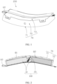
FIG. 1 is a three-dimensional schematic structural diagram of a battery pack according to an embodiment; -
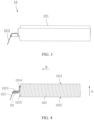
FIG. 2 is a schematic sectional view of a structure of the battery pack shown inFIG. 1 ; -
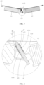
FIG. 3 is a side view of a battery cell in the battery pack shown inFIG. 1 ; -
FIG. 4 is a schematic sectional view of a structure of the battery cell shown inFIG. 3 ; -
FIG. 5 is a schematic structural diagram of a battery module of the battery pack shown inFIG. 2 ; -
FIG. 6 is a close-up view of a local structure of the battery module shown inFIG. 5 ; -
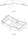
FIG. 7 is a schematic sectional view of a structure of the battery module shown inFIG. 5 ; -
FIG. 8 is a close-up view of a local structure of the battery module shown inFIG. 7 ; -
FIG. 9 is a schematic structural diagram of a first battery cell in the battery module shown inFIG. 5 ; -
FIG. 10 is a schematic structural diagram of a second battery cell in the battery module shown inFIG. 5 ; -
FIG. 11 is a side view of the battery pack shown inFIG. 1 ; -
FIG. 12 is a schematic structural diagram of a part of a shell of the battery pack shown inFIG. 1 ; -
FIG. 13 is a schematic structural exploded view of a battery pack according to an embodiment; and -
FIG. 14 is a brief structural diagram of an electronic device according to an embodiment. -
Battery module 100 Battery cell 10 Housing 101 First main plane 1011 Second main plane 1012 Seal edge 1013 First surface 1014 Second surface 1015 Electrode assembly 102 Tab 103 First battery cell 11 First tab 113 First soldering portion 1131 Second battery cell 12 Second tab 123 Second soldering portion 1231 Spacer 14 First circuit board 20 First side 21 Second side 22 First connecting strip 30 First fixing portion 31 First connecting portion 32 Second connecting strip 40 Second fixing portion 41 Second connecting portion 42 Insulation piece 50 First insulation piece 51 First opening 511 Second insulation piece 52 Second opening 521 Second circuit board 60 Shell 70 Arc bottom plate 71 First groove 711 Second groove 712 Side plate 72 Injection hole 721 Arc cover plate 73 First spacer 81 Second spacer 82 Fastener 90 First bracket 91 Second bracket 92 Connecting portion 93 Through-hole 931 Battery pack 200 Electronic device 300 Electrical component 301 - The following clearly and thoroughly describes the technical solutions in some embodiments of this application with reference to the drawings hereto. Evidently, the described some embodiments are merely a part of but not all of some embodiments of this application.
- It is hereby noted that a component referred to as being "fixed to" another component may be directly fixed onto the other component or may be fixed onto the other component through an intermediate component. A component considered to be "connected to" another component may be directly connected to the other component or may be connected to the other component through an intermediate component. A component considered to be "disposed on" another component may be directly disposed on the other component or may be disposed on the other component through an intermediate component. The terms "vertical", "horizontal", "left", "right" and similar expressions used herein are merely for ease of description.
- Unless otherwise defined, all technical and scientific terms used herein bear the same meanings as what is normally understood by a person skilled in the technical field of this application. The terms used in the specification of this application are merely intended to describe specific some embodiments but not to limit this application. The term "and/or" used herein is intended to include any and all combinations of one or more relevant items recited.
- An embodiment of this application provides a battery module. The battery module includes a cell assembly and a first circuit board. The cell assembly includes a plurality of battery cells. The plurality of battery cells are connected to the first circuit board. The plurality of battery cells include a first battery cell and a second battery cell, and the first battery cell is inclined with respect to the second battery cell. The first circuit board is disposed between the first battery cell and the second battery cell, the first circuit board is inclined with respect to the first battery cell, and the first circuit board is inclined with respect to the second battery cell.
- In the battery module, the space inside a battery is sufficiently utilized by disposing the first circuit board in the space between the first battery cell and the second battery cell, thereby effectively improving an energy density.
- The following describes some embodiments of this application in detail. To the extent that no conflict occurs, the following some embodiments and the features in some embodiments may be combined with each other.
- Referring to
FIG. 1 and FIG. 2 , in an embodiment, thebattery pack 200 includes abattery module 100 and ashell 70. Thebattery module 100 is accommodated in theshell 70. Thebattery module 100 includes a cell assembly and afirst circuit board 20. The cell assembly includes a plurality ofbattery cells 10. Thebattery cells 10 are connected to thefirst circuit board 20. - Still referring to
FIG. 3 and FIG. 4 , in an embodiment of this application, the plurality ofbattery cells 10 are pouch-type cells. Eachbattery cell 10 includes ahousing 101 and anelectrode assembly 102 accommodated in thehousing 101. Theelectrode assembly 102 includes atab 103. Thetab 103 extends out of thehousing 101. Along a thickness direction of thebattery cell 10, that is, a direction indicated by the arrow A inFIG. 4 , thehousing 101 includes a firstmain plane 1011 and a secondmain plane 1012 that are disposed opposite to each other. Further, aseal edge 1013 is disposed at one end of thehousing 101 along a length direction of thebattery cell 10, that is, a direction indicated by the arrow B inFIG. 4 . Thetab 103 extends out of thehousing 101 from theseal edge 1013. Thehousing 101 further includes afirst surface 1014 and asecond surface 1015. Thefirst surface 1014 connects theseal edge 1013 and the firstmain plane 1011. Thesecond surface 1015 connects theseal edge 1013 and the secondmain plane 1012. Along the thickness direction, the width of thefirst surface 1014 is greater than the width of thesecond surface 1015. - Referring to
FIG. 5 and FIG. 6 , in an embodiment of this application, the plurality ofbattery cells 10 include afirst battery cell 11 and asecond battery cell 12. Thefirst battery cell 11 is inclined with respect to thesecond battery cell 12. The structure of thefirst battery cell 11 is approximately identical to the structure of thesecond battery cell 12. In some embodiments, the plurality ofbattery cells 10 may further include a third battery cell, a fourth battery cell, and the like, without being limited in this application. Thefirst circuit board 20 is disposed between thefirst battery cell 11 and thesecond battery cell 12. Thefirst circuit board 20 is inclined with respect to thefirst battery cell 11, and thefirst circuit board 20 is inclined with respect to thesecond battery cell 12. In thebattery module 100, thefirst circuit board 20 is disposed in the space vacated by tilting between thefirst battery cell 11 and thesecond battery cell 12, thereby sufficiently utilizing the space inside the battery and effectively increasing the energy density. - One end of the
first circuit board 20 tilts closer to thefirst surface 1014 of thefirst battery cell 11, and an opposite end of thefirst circuit board 20 tilts closer to thefirst surface 1014 of thesecond battery cell 12. Because the width of thefirst surface 1014 is greater than the width of thesecond surface 1015, thefirst circuit board 20 can be disposed more efficiently by use of the relatively large width of thefirst surface 1014 when both opposite ends of thefirst circuit board 20 tilt toward thefirst surface 1014. Thefirst circuit board 20 is at an acute angle a to theseal edge 1013 of thefirst battery cell 11. The range of the acute angle a may be adjusted according to the tilt angle of thebattery cell 10 and the tilt angle of thefirst circuit board 20. A preferred acute angle range is 30° to 60°. - The
first surface 1014 of thefirst battery cell 11 is opposite to thesecond surface 1015 of thesecond battery cell 12. Thesecond surface 1015 of thefirst battery cell 11 is opposite to thefirst surface 1014 of thesecond battery cell 12. - Still referring to
FIG. 7 and FIG. 8 , thefirst battery cell 11 includes afirst tab 113. Thesecond battery cell 12 includes asecond tab 123. Thefirst tab 113 is opposite to thesecond tab 123. Thefirst circuit board 20 is disposed between thefirst tab 113 and thesecond tab 123. Thefirst tab 113 tilts closer to thefirst surface 1014 of thefirst battery cell 11, and thesecond tab 123 tilts closer to thesecond surface 1015 of thesecond battery cell 12. Thefirst circuit board 20 includes afirst side 21 and asecond side 22 that are disposed opposite to each other. Thefirst tab 113 is disposed on thefirst side 21. Thesecond tab 123 is disposed on thesecond side 22. Thefirst tab 113 and thesecond tab 123 may be directly soldered to thefirst circuit board 20, for example, by SMT or DIP, or may be connected to thefirst circuit board 20 by other connecting strips. Thefirst tab 113 and thesecond tab 123 are made of a conductive metal or alloy, such as copper, aluminum, nickel, nickel-clad copper, nickel-clad aluminum, and the like. Thefirst tab 113 and thesecond tab 123 is highly bendable, and can be bent by different angles as required by thebattery module 100, thereby occupying a smaller space. - Still referring to
FIG. 7 and FIG. 8 , in this embodiment, thebattery module 100 further includes a first connectingstrip 30 and a second connectingstrip 40. The first connectingstrip 30 is configured to connect thefirst tab 113 and thefirst circuit board 20. The second connectingstrip 40 is configured to connect thesecond tab 123 and thefirst circuit board 20. Thefirst tab 113 includes afirst soldering portion 1131, and thesecond tab 123 includes asecond soldering portion 1231. The first connectingstrip 30 includes a first fixingportion 31 and a first connectingportion 32. Thefirst fixing portion 31 is soldered to thefirst circuit board 20. The first connectingportion 32 is welded to thefirst soldering portion 1131. Thefirst soldering portion 1131 is disposed between the first fixingportion 31 and the first connectingportion 32. The second connectingstrip 40 includes asecond fixing portion 41 and a second connectingportion 42. Thesecond fixing portion 41 is soldered to thefirst circuit board 20. The second connectingportion 42 is welded to thesecond soldering portion 1231. Thesecond soldering portion 1231 is disposed between the second fixingportion 41 and the second connectingportion 42. - To facilitate the manufacture of the
battery module 100, before thebattery cell 10 is connected to thefirst circuit board 20, the first connectingstrip 30 and the second connectingstrip 40 are of an L-shaped structure. Thefirst fixing portion 31 is approximately perpendicular to the first connectingportion 32. Thesecond fixing portion 41 is approximately perpendicular to the second connectingportion 42. Thefirst soldering portion 1131 is welded to the first connectingportion 32, thesecond soldering portion 1231 is welded to the second connectingportion 42. Thefirst fixing portion 31 is soldered to thefirst circuit board 20, the second fixingportion 41 is soldered to thefirst circuit board 20. Thefirst battery cell 11 and thesecond battery cell 12 are perpendicular to thefirst circuit board 20. Subsequently, thefirst tab 113 and thesecond tab 123 are bent so that thefirst soldering portion 1131 is sandwiched between the first fixingportion 31 and the first connectingportion 32. Thesecond soldering portion 1231 is sandwiched between the second fixingportion 41 and the second connectingportion 42. In addition, thesecond battery cell 12 is inclined with respect to thefirst battery cell 11. Thefirst circuit board 20 is inclined with respect to thefirst battery cell 11, thefirst circuit board 20 is inclined with respect to thesecond battery cell 12. By disposing the first connectingstrip 30 and the second connectingstrip 40, the space of thefirst circuit board 20 can be utilized more efficiently. For example, the first fixingportion 31 and the second fixingportion 41 may be soldered onto different positions of the circuit board according to the design of thefirst circuit board 20. In addition, the connecting strips facilitate control of the bending angle. For example, the first fixingportion 31 and the first connectingportion 32 may be bent to form different angles as required. - In this embodiment, the first fixing
portion 31 and the first connectingportion 32 clamp thefirst soldering portion 1131. One surface of thefirst soldering portion 1131 is in contact with the first connectingportion 32, and an opposite surface of thefirst soldering portion 1131 is in contact with the first fixingportion 31. Thesecond fixing portion 41 and the second connectingportion 42 clamp thesecond soldering portion 1231. One surface of thesecond soldering portion 1231 is in contact with the second connectingportion 42, and an opposite surface of thesecond soldering portion 1231 is in contact with the second fixingportion 41. Through contact and clamping, the first connectingstrip 30 can be fixed to thefirst soldering portion 1131 more stably, thereby preventing the first connectingstrip 30 from detaching from thefirst soldering portion 1131 in the case of dropping or in other cases. In other examples, the opposite surface of thefirst soldering portion 1131 may be fixedly connected to the first fixingportion 31 in other ways such as gluing. - Referring to
FIG. 4 ,FIG. 9, and FIG. 10 , thebattery module 100 further includes aninsulation piece 50. Theinsulation piece 50 wraps at least a part of aseal edge 1013 of thebattery cell 10. Theinsulation piece 50 includes afirst insulation piece 51 and asecond insulation piece 52. Thefirst insulation piece 51 wraps at least a part of theseal edge 1013 of thefirst battery cell 11. Thesecond insulation piece 52 wraps at least a part of theseal edge 1013 of thesecond battery cell 12. Afirst opening 511 is provided on thefirst insulation piece 51. Thefirst tab 113 protrudes from thefirst opening 511. Asecond opening 521 is provided on thesecond insulation piece 52. Thesecond tab 123 protrudes from thesecond opening 521. Theinsulation piece 50 can support theseal edge 1013 on the one hand to prevent deformation, and can isolate thetab 103 on the other hand to reduce the probability of short circuits. - Still referring to
FIG. 1 and FIG. 2 , thebattery pack 200 further includes asecond circuit board 60. One end of thesecond circuit board 60 is connected to thefirst circuit board 20. Another end of thesecond circuit board 60 protrudes out of theshell 70. In an embodiment of this application, thesecond circuit board 60 is a flexible circuit board. Along the length direction of the cell assembly, thesecond circuit board 60 protrudes from one side of theshell 70. - The
battery pack 200 further includes aspacer 14. Thespacer 14 is disposed on the firstmain plane 1011 and the secondmain plane 1012 of thebattery cell 10 along the thickness direction of thebattery cell 10. Thespacer 14 is made of a material including but not limited to foam, and is configured to absorb an expansion volume of thebattery cell 10. - The shell includes an
arc bottom plate 71,side plates 72 disposed around thearc bottom plate 71, and anarc cover plate 73. Theside plates 72 and thearc bottom plate 71 are formed in one piece. Lateral edges of thearc cover plate 73 are fixedly connected to theside plates 72 by, but without being limited to, snapping, riveting, welding, gluing, or the like. To reduce damage to theshell 70, thesecond circuit board 60 protrudes from between thearc cover plate 73 and one of theside plates 72. Referring toFIG. 11 , an arc radius R1 of thearc bottom plate 71 is 85 to 110 mm, and an arc radius R2 of thearc cover plate 73 is 80 to 100 mm. In this embodiment, thearc bottom plate 71 is a plastic part formed in one piece, and thearc cover plate 73 is a steel sheet. The steel sheet improves the resistance-to-impact of thebattery pack 200 impacted by an external force. The integrally formed steel sheet avoids harm to the user during failure of the battery. In an embodiment, thebattery pack 200 is applicable to headsets. Thearc cover plate 73 is close to the user's head. The steel sheet is stronger than a plastic piece. When the battery fails, thearc bottom plate 71 is damaged first, thereby protecting the head. - Referring to
FIG. 2 andFIG. 12 , afirst groove 711 and asecond groove 712 are disposed in the inner sidewall of thearc bottom plate 71, and are configured to provide an expansion space for thefirst battery cell 11 and thesecond battery cell 12 respectively. Thebattery pack 200 further includes afirst spacer 81 and asecond spacer 82. Thefirst spacer 81 is disposed between thefirst battery cell 11 and thefirst groove 711. Thesecond spacer 82 is disposed between thesecond battery cell 12 and thesecond groove 712. Thefirst spacer 81 covers thefirst groove 711, and thesecond spacer 82 covers thesecond groove 712. Thefirst spacer 81 and thesecond spacer 82 are configured to support thefirst battery cell 11 and thesecond battery cell 12. - Referring to
FIG. 13 , in another embodiment, the structure of thebattery pack 200 is approximately identical to that in the preceding embodiment except that thebattery pack 200 further includes afastener 90 configured to fix the cell assembly. Thefastener 90 is accommodated in a space between theshell 70 and the cell assembly. Thefastener 90 includes afirst bracket 91, asecond bracket 92, and a connectingportion 93. Thefirst bracket 91 and thesecond bracket 92 are disposed on two opposite sides of the connectingportion 93 respectively. Thefirst bracket 91 is inclined with respect to the connectingportion 93, and thesecond bracket 92 is inclined with respect to the connectingportion 93. Thefirst battery cell 11 is held by thefirst bracket 91, and thesecond battery cell 12 is held by thesecond bracket 92. Thefirst circuit board 20 is attached obliquely to the connectingportion 93. In other embodiments, thefastener 90 is resin that fills the space between theshell 70 and the cell assembly. The resin fills a clearance between theshell 70 and the cell assembly to fix the cell assembly. The resin may be plastic. Aninjection hole 721 is provided on theside plate 72 of theshell 70. The resin is injected to fill in theshell 70 through theinjection hole 721 by low-pressure injection molding. The resin can flow from a through-hole 931 into the clearance between thefirst battery cell 11, thesecond battery cell 12, and thefirst circuit board 20, so as to ensure that the clearance can be filled. Thebattery pack 200 filled with the resin is waterproof. In addition, the resin exerts a protective effect on thebattery cell 10 to some extent to prevent damage to thebattery cell 10 that is dropped accidentally or in other circumstances. In other embodiments, the resin is a potting glue. The potting glue is injected to fill in theshell 70 through theinjection hole 721. In other embodiments, thefastener 90 may include a fixing bracket and resin concurrently to implement securer fixing. - Referring to
FIG. 14 , an embodiment of this application further provides anelectronic device 300. Theelectronic device 300 includes anelectrical component 301 and thebattery pack 200 according to any one or any combination of some embodiments described above. Theelectrical component 301 is electrically connected to thebattery pack 200. - The foregoing some embodiments are merely intended for describing the technical solutions of this application but not intended as a limitation. Although this application is described in detail with reference to the foregoing exemplary someembodiments, a person of ordinary skill in the art understands that modifications or equivalent substitutions may be made to the technical solutions of this application without departing from the spirit and scope of the technical solutions of this application.
Claims (20)
- A battery module, comprising:a cell assembly comprising a plurality of battery cells; anda first circuit board, the plurality of battery cells are connected to the first circuit board;wherein the plurality of battery cells comprise a first battery cell and a second battery cell, and the first battery cell is inclined with respect to the second battery cell; andthe first circuit board is disposed between the first battery cell and the second battery cell, the first circuit board is inclined with respect to the first battery cell, and the first circuit board is inclined with respect to the second battery cell.
- The battery module according to claim 1, wherein each battery cell comprises a housing and an electrode assembly accommodated in the housing, and the electrode assembly comprises a tab;the housing comprises a first main plane and a second main plane disposed opposite to each other along a thickness direction of the battery cell, a seal edge is disposed at one end of the housing along a length direction of the battery cell, and the tab extends out of the housing from the seal edge;the first battery cell comprises a first tab, the second battery cell comprises a second tab, and the first tab is opposite to the second tab;the housing further comprises a first surfaceand a second surface, the first surface connects the seal edge and the first main plane, the second surface connects the seal edge and the second main plane, and a width of the first surface is greater than a width of the second surface along the thickness direction;one end of the first circuit board tilts closer to the first surface of the first battery cell, and an opposite end of the first circuit board tilts closer to the first surface of the second battery cell.
- The battery module according to claim 2, wherein the first circuit board is disposed between the first tab and the second tab.
- The battery module according to claim 2 or 3, wherein the first tab comprises a first soldering portion, and the second tab comprises a second soldering portion;the battery module comprises a first connecting stripand a second connecting strip ;the first connecting strip comprises a first fixing portion and a first connecting portion, the first fixing portion is soldered to the first circuit board, the first connecting portion is welded to the first soldering portion, and the first soldering portion is disposed between the first fixing portion and the first connecting portion; andthe second connecting strip comprises a second fixing portion and a second connecting portion, the second fixing portion is soldered to the first circuit board, the second connecting portion is welded to the second soldering portion, and the second soldering portion is disposed between the second fixing portion and the second connecting portion.
- The battery module according to claim 4, wherein the first fixing portion and the first connecting portion clamp the first soldering portion, one surface of the first soldering portion is in contact with the first connecting portion, and an opposite surface of the first soldering portion is in contact with the first fixing portion; and
the second fixing portion and the second connecting portion clamp the second soldering portion, one surface of the second soldering portion is in contact with the second connecting portion, and an opposite surface of the second soldering portion is in contact with the second fixing portion. - The battery module according to claim 4, wherein the first soldering portion is disposed between the first surface of the first battery cell and the first circuit board, and the second soldering portion is disposed between the second surface of the second battery cell and the first circuit board.
- The battery module according to claim 4, wherein the first circuit board comprises a first side and a second side disposed opposite to each other, the first tab is disposed on the first side, and the second tab is disposed on the second side.
- The battery module according to claim 2, wherein the first circuit board is at an acute angle to the seal edge of the first battery cell, and the acute angle ranges from 30° to 60°.
- The battery module according to claim 2, wherein the battery module further comprises a first insulation piece and a second insulation piece, the first insulation piece wraps at least a part of the seal edge of the first battery cell, and the second insulation piece wraps at least a part of the seal edge of the second battery cell.
- The battery module according to claim 9, wherein a first opening is provided on the first insulation piece, the first tab protrudes from the first opening, a second opening is provided on the second insulation piece, and the second tab protrudes from the second opening.
- A battery pack, wherein the battery pack comprises a shell and the battery module according to any one of claims 1 to 10, and the battery module is accommodated in the shell.
- The battery pack according to claim 11, wherein the battery pack further comprises a second circuit board, one end of the second circuit board is connected to the first circuit board of the battery module, and another end of the second circuit board protrudes out of the shell.
- The battery pack according to claim 12, wherein the shell comprises an arc bottom plate, a first groove and a second groove are provided on an inner sidewall of the arc bottom plate; the battery pack further comprises a first spacer and a second spacer, the first spacer is disposed between the first battery cell of the battery module and the first groove, and the second spacer is disposed between the second battery cell of the battery module and the second groove.
- The battery pack according to claim 13, wherein the first spacer covers the first groove, and the second spacer covers the second groove.
- The battery pack according to claim 13, wherein an arc radius of the arc bottom plate is 85 to 110 mm.
- The battery pack according to claim 13, wherein the shell further comprises a side plate and an arc cover plate, the side plate is disposed around the arc bottom plate, the arc cover plate is fixedly connected to the side plate, and an arc radius of the arc cover plate is 80 to 100 mm.
- The battery pack according to claim 11, wherein the battery pack further comprises a fastener, the fastener comprises a first bracket, a second bracket, and a connecting portion; the first bracket and the second bracket are disposed on two opposite sides of the connecting portion respectively; and the first battery cell of the battery module is held by the first bracket, the second battery cell is held by the second bracket, and the first circuit board is attached to the connecting portion.
- The battery pack according to claim 11, wherein resin is disposed in the shell and is configured to fill a clearance between the shell and the cell assembly of the battery module.
- The battery pack according to claim 18, wherein an injection hole is provided on the shell, and the resin fills the shell by low-pressure injection molding.
- An electronic device, wherein the electronic device comprises an electrical component and the battery pack according to any one of claims 11 to 19, and the electrical component is electrically connected to the battery pack.
Applications Claiming Priority (1)
| Application Number | Priority Date | Filing Date | Title |
|---|---|---|---|
| PCT/CN2020/119462 WO2022067693A1 (en) | 2020-09-30 | 2020-09-30 | Battery module, battery pack, and electronic device |
Publications (3)
| Publication Number | Publication Date |
|---|---|
| EP4207475A1 true EP4207475A1 (en) | 2023-07-05 |
| EP4207475A4 EP4207475A4 (en) | 2024-07-31 |
| EP4207475B1 EP4207475B1 (en) | 2026-02-18 |
Family
ID=80949296
Family Applications (1)
| Application Number | Title | Priority Date | Filing Date |
|---|---|---|---|
| EP20955718.0A Active EP4207475B1 (en) | 2020-09-30 | 2020-09-30 | Battery module, battery pack, and electronic device |
Country Status (4)
| Country | Link |
|---|---|
| US (1) | US20230238662A1 (en) |
| EP (1) | EP4207475B1 (en) |
| CN (1) | CN116325337A (en) |
| WO (1) | WO2022067693A1 (en) |
Families Citing this family (3)
| Publication number | Priority date | Publication date | Assignee | Title |
|---|---|---|---|---|
| CN115117564B (en) * | 2022-07-07 | 2023-07-07 | 天津市捷威动力工业有限公司 | Connection structure and connection method of battery components, battery unit, module and system |
| CN115498368B (en) * | 2022-09-20 | 2023-07-07 | 天津市捷威动力工业有限公司 | Battery cell connection structure, connection method thereof, battery cell unit and battery module |
| CN116073043B (en) * | 2023-03-07 | 2023-06-20 | 星恒电源股份有限公司 | Positive electrode cover plate, battery cell and assembly method |
Family Cites Families (8)
| Publication number | Priority date | Publication date | Assignee | Title |
|---|---|---|---|---|
| CN201781031U (en) * | 2010-04-29 | 2011-03-30 | 上海比亚迪有限公司 | Flexible packaging battery pack |
| US9578146B2 (en) * | 2014-07-08 | 2017-02-21 | Htc Corporation | Electronic assembly and electronic apparatus |
| KR102256293B1 (en) * | 2014-07-28 | 2021-05-26 | 삼성에스디아이 주식회사 | Battery pack |
| US20160301044A1 (en) * | 2015-04-10 | 2016-10-13 | Zhen Huang | Flexible Battery System for Portable Device |
| CN205488322U (en) * | 2016-03-30 | 2016-08-17 | 珠海科斯特电源有限公司 | Novel built -in battery tab and protection shield connection structure |
| US11670805B2 (en) * | 2017-10-31 | 2023-06-06 | Snap Inc. | Nested PCM battery pack |
| CN111435724B (en) * | 2019-01-11 | 2024-09-06 | 孚能科技(赣州)股份有限公司 | Battery module, battery system and electric vehicle having the same |
| CN209963125U (en) * | 2019-07-22 | 2020-01-17 | 深圳市创联智控新能源有限公司 | Flexible battery pack |
-
2020
- 2020-09-30 EP EP20955718.0A patent/EP4207475B1/en active Active
- 2020-09-30 WO PCT/CN2020/119462 patent/WO2022067693A1/en not_active Ceased
- 2020-09-30 CN CN202080105753.2A patent/CN116325337A/en active Pending
-
2023
- 2023-03-28 US US18/191,228 patent/US20230238662A1/en active Pending
Also Published As
| Publication number | Publication date |
|---|---|
| WO2022067693A1 (en) | 2022-04-07 |
| EP4207475A4 (en) | 2024-07-31 |
| EP4207475B1 (en) | 2026-02-18 |
| US20230238662A1 (en) | 2023-07-27 |
| CN116325337A (en) | 2023-06-23 |
Similar Documents
| Publication | Publication Date | Title |
|---|---|---|
| US20230238662A1 (en) | Battery module, battery pack, and electronic device | |
| CN106876621B (en) | Rechargeable Battery Module | |
| KR101311252B1 (en) | Secondary Battery Pack | |
| KR101293591B1 (en) | Secondary Battery Pack | |
| KR101227870B1 (en) | Secondary battery pack having pcm case | |
| EP2731175B1 (en) | Secondary battery pack | |
| KR101237756B1 (en) | Secondary Battery Pack Having PCM Case | |
| US8658294B2 (en) | Protective circuit module and secondary battery having the same | |
| US20240055690A1 (en) | Battery pack and method of manufacturing the same | |
| US9941494B2 (en) | Battery pack | |
| US11380957B2 (en) | Battery package housing and battery pack | |
| KR101430619B1 (en) | Battery Pack | |
| KR20170117756A (en) | Battery pack | |
| US8685551B2 (en) | Battery pack | |
| JP4488730B2 (en) | Thin battery pack | |
| CN210668435U (en) | Batteries and Electronic Equipment | |
| US20130115481A1 (en) | Battery pack | |
| CN213459997U (en) | Battery modules, battery packs and electronic devices | |
| US8652662B2 (en) | Battery pack and method of fabricating the same | |
| EP4593188A1 (en) | Battery module and battery pack including same | |
| US20220294031A1 (en) | Metal-shell battery and electronic device | |
| KR101502899B1 (en) | Battery Pack | |
| CN217641647U (en) | Protection board subassembly, battery and electronic equipment of battery | |
| KR20240130250A (en) | A Battery Pack Having Excellent Impact Resistance | |
| JP4961669B2 (en) | Battery pack structure |
Legal Events
| Date | Code | Title | Description |
|---|---|---|---|
| STAA | Information on the status of an ep patent application or granted ep patent |
Free format text: STATUS: THE INTERNATIONAL PUBLICATION HAS BEEN MADE |
|
| PUAI | Public reference made under article 153(3) epc to a published international application that has entered the european phase |
Free format text: ORIGINAL CODE: 0009012 |
|
| STAA | Information on the status of an ep patent application or granted ep patent |
Free format text: STATUS: REQUEST FOR EXAMINATION WAS MADE |
|
| 17P | Request for examination filed |
Effective date: 20230327 |
|
| AK | Designated contracting states |
Kind code of ref document: A1 Designated state(s): AL AT BE BG CH CY CZ DE DK EE ES FI FR GB GR HR HU IE IS IT LI LT LU LV MC MK MT NL NO PL PT RO RS SE SI SK SM TR |
|
| DAV | Request for validation of the european patent (deleted) | ||
| DAX | Request for extension of the european patent (deleted) | ||
| A4 | Supplementary search report drawn up and despatched |
Effective date: 20240702 |
|
| RIC1 | Information provided on ipc code assigned before grant |
Ipc: H01M 50/516 20210101ALI20240627BHEP Ipc: H01M 50/519 20210101AFI20240627BHEP |
|
| GRAP | Despatch of communication of intention to grant a patent |
Free format text: ORIGINAL CODE: EPIDOSNIGR1 |
|
| STAA | Information on the status of an ep patent application or granted ep patent |
Free format text: STATUS: GRANT OF PATENT IS INTENDED |
|
| RAP1 | Party data changed (applicant data changed or rights of an application transferred) |
Owner name: NINGDE AMPEREX TECHNOLOGY LIMITED |
|
| INTG | Intention to grant announced |
Effective date: 20250912 |
|
| GRAS | Grant fee paid |
Free format text: ORIGINAL CODE: EPIDOSNIGR3 |
|
| GRAA | (expected) grant |
Free format text: ORIGINAL CODE: 0009210 |
|
| STAA | Information on the status of an ep patent application or granted ep patent |
Free format text: STATUS: THE PATENT HAS BEEN GRANTED |
|
| AK | Designated contracting states |
Kind code of ref document: B1 Designated state(s): AL AT BE BG CH CY CZ DE DK EE ES FI FR GB GR HR HU IE IS IT LI LT LU LV MC MK MT NL NO PL PT RO RS SE SI SK SM TR |
|
| REG | Reference to a national code |
Ref country code: CH Ref legal event code: F10 Free format text: ST27 STATUS EVENT CODE: U-0-0-F10-F00 (AS PROVIDED BY THE NATIONAL OFFICE) Effective date: 20260218 Ref country code: GB Ref legal event code: FG4D |
|
| REG | Reference to a national code |
Ref country code: DE Ref legal event code: R096 Ref document number: 602020067332 Country of ref document: DE |
|
| REG | Reference to a national code |
Ref country code: IE Ref legal event code: FG4D |
|
| P01 | Opt-out of the competence of the unified patent court (upc) registered |
Free format text: CASE NUMBER: UPC_APP_0005718_4207475/2026 Effective date: 20260217 |
|
| REG | Reference to a national code |
Ref country code: NL Ref legal event code: FP |