EP4207471A1 - High-voltage box, battery and electrical device - Google Patents
High-voltage box, battery and electrical device Download PDFInfo
- Publication number
- EP4207471A1 EP4207471A1 EP22754755.1A EP22754755A EP4207471A1 EP 4207471 A1 EP4207471 A1 EP 4207471A1 EP 22754755 A EP22754755 A EP 22754755A EP 4207471 A1 EP4207471 A1 EP 4207471A1
- Authority
- EP
- European Patent Office
- Prior art keywords
- high voltage
- voltage box
- lower housing
- battery
- relay
- Prior art date
- Legal status (The legal status is an assumption and is not a legal conclusion. Google has not performed a legal analysis and makes no representation as to the accuracy of the status listed.)
- Pending
Links
Images



Classifications
-
- H—ELECTRICITY
- H01—ELECTRIC ELEMENTS
- H01M—PROCESSES OR MEANS, e.g. BATTERIES, FOR THE DIRECT CONVERSION OF CHEMICAL ENERGY INTO ELECTRICAL ENERGY
- H01M10/00—Secondary cells; Manufacture thereof
- H01M10/60—Heating or cooling; Temperature control
- H01M10/61—Types of temperature control
- H01M10/613—Cooling or keeping cold
-
- B—PERFORMING OPERATIONS; TRANSPORTING
- B60—VEHICLES IN GENERAL
- B60R—VEHICLES, VEHICLE FITTINGS, OR VEHICLE PARTS, NOT OTHERWISE PROVIDED FOR
- B60R16/00—Electric or fluid circuits specially adapted for vehicles and not otherwise provided for; Arrangement of elements of electric or fluid circuits specially adapted for vehicles and not otherwise provided for
- B60R16/02—Electric or fluid circuits specially adapted for vehicles and not otherwise provided for; Arrangement of elements of electric or fluid circuits specially adapted for vehicles and not otherwise provided for electric constitutive elements
- B60R16/023—Electric or fluid circuits specially adapted for vehicles and not otherwise provided for; Arrangement of elements of electric or fluid circuits specially adapted for vehicles and not otherwise provided for electric constitutive elements for transmission of signals between vehicle parts or subsystems
- B60R16/0239—Electronic boxes
-
- H—ELECTRICITY
- H01—ELECTRIC ELEMENTS
- H01M—PROCESSES OR MEANS, e.g. BATTERIES, FOR THE DIRECT CONVERSION OF CHEMICAL ENERGY INTO ELECTRICAL ENERGY
- H01M10/00—Secondary cells; Manufacture thereof
- H01M10/60—Heating or cooling; Temperature control
- H01M10/65—Means for temperature control structurally associated with the cells
- H01M10/653—Means for temperature control structurally associated with the cells characterised by electrically insulating or thermally conductive materials
-
- B—PERFORMING OPERATIONS; TRANSPORTING
- B60—VEHICLES IN GENERAL
- B60K—ARRANGEMENT OR MOUNTING OF PROPULSION UNITS OR OF TRANSMISSIONS IN VEHICLES; ARRANGEMENT OR MOUNTING OF PLURAL DIVERSE PRIME-MOVERS IN VEHICLES; AUXILIARY DRIVES FOR VEHICLES; INSTRUMENTATION OR DASHBOARDS FOR VEHICLES; ARRANGEMENTS IN CONNECTION WITH COOLING, AIR INTAKE, GAS EXHAUST OR FUEL SUPPLY OF PROPULSION UNITS IN VEHICLES
- B60K1/00—Arrangement or mounting of electrical propulsion units
-
- B—PERFORMING OPERATIONS; TRANSPORTING
- B60—VEHICLES IN GENERAL
- B60K—ARRANGEMENT OR MOUNTING OF PROPULSION UNITS OR OF TRANSMISSIONS IN VEHICLES; ARRANGEMENT OR MOUNTING OF PLURAL DIVERSE PRIME-MOVERS IN VEHICLES; AUXILIARY DRIVES FOR VEHICLES; INSTRUMENTATION OR DASHBOARDS FOR VEHICLES; ARRANGEMENTS IN CONNECTION WITH COOLING, AIR INTAKE, GAS EXHAUST OR FUEL SUPPLY OF PROPULSION UNITS IN VEHICLES
- B60K1/00—Arrangement or mounting of electrical propulsion units
- B60K1/04—Arrangement or mounting of electrical propulsion units of the electric storage means for propulsion
-
- H—ELECTRICITY
- H01—ELECTRIC ELEMENTS
- H01M—PROCESSES OR MEANS, e.g. BATTERIES, FOR THE DIRECT CONVERSION OF CHEMICAL ENERGY INTO ELECTRICAL ENERGY
- H01M10/00—Secondary cells; Manufacture thereof
- H01M10/60—Heating or cooling; Temperature control
- H01M10/62—Heating or cooling; Temperature control specially adapted for specific applications
- H01M10/625—Vehicles
-
- H—ELECTRICITY
- H01—ELECTRIC ELEMENTS
- H01M—PROCESSES OR MEANS, e.g. BATTERIES, FOR THE DIRECT CONVERSION OF CHEMICAL ENERGY INTO ELECTRICAL ENERGY
- H01M10/00—Secondary cells; Manufacture thereof
- H01M10/60—Heating or cooling; Temperature control
- H01M10/64—Heating or cooling; Temperature control characterised by the shape of the cells
- H01M10/643—Cylindrical cells
-
- H—ELECTRICITY
- H01—ELECTRIC ELEMENTS
- H01M—PROCESSES OR MEANS, e.g. BATTERIES, FOR THE DIRECT CONVERSION OF CHEMICAL ENERGY INTO ELECTRICAL ENERGY
- H01M10/00—Secondary cells; Manufacture thereof
- H01M10/60—Heating or cooling; Temperature control
- H01M10/65—Means for temperature control structurally associated with the cells
- H01M10/655—Solid structures for heat exchange or heat conduction
- H01M10/6554—Rods or plates
-
- H—ELECTRICITY
- H01—ELECTRIC ELEMENTS
- H01M—PROCESSES OR MEANS, e.g. BATTERIES, FOR THE DIRECT CONVERSION OF CHEMICAL ENERGY INTO ELECTRICAL ENERGY
- H01M10/00—Secondary cells; Manufacture thereof
- H01M10/60—Heating or cooling; Temperature control
- H01M10/65—Means for temperature control structurally associated with the cells
- H01M10/655—Solid structures for heat exchange or heat conduction
- H01M10/6556—Solid parts with flow channel passages or pipes for heat exchange
-
- H—ELECTRICITY
- H01—ELECTRIC ELEMENTS
- H01M—PROCESSES OR MEANS, e.g. BATTERIES, FOR THE DIRECT CONVERSION OF CHEMICAL ENERGY INTO ELECTRICAL ENERGY
- H01M10/00—Secondary cells; Manufacture thereof
- H01M10/60—Heating or cooling; Temperature control
- H01M10/65—Means for temperature control structurally associated with the cells
- H01M10/656—Means for temperature control structurally associated with the cells characterised by the type of heat-exchange fluid
- H01M10/6567—Liquids
- H01M10/6568—Liquids characterised by flow circuits, e.g. loops, located externally to the cells or cell casings
-
- H—ELECTRICITY
- H01—ELECTRIC ELEMENTS
- H01M—PROCESSES OR MEANS, e.g. BATTERIES, FOR THE DIRECT CONVERSION OF CHEMICAL ENERGY INTO ELECTRICAL ENERGY
- H01M10/00—Secondary cells; Manufacture thereof
- H01M10/60—Heating or cooling; Temperature control
- H01M10/65—Means for temperature control structurally associated with the cells
- H01M10/658—Means for temperature control structurally associated with the cells by thermal insulation or shielding
-
- H—ELECTRICITY
- H01—ELECTRIC ELEMENTS
- H01M—PROCESSES OR MEANS, e.g. BATTERIES, FOR THE DIRECT CONVERSION OF CHEMICAL ENERGY INTO ELECTRICAL ENERGY
- H01M10/00—Secondary cells; Manufacture thereof
- H01M10/60—Heating or cooling; Temperature control
- H01M10/66—Heat-exchange relationships between the cells and other systems, e.g. central heating systems or fuel cells
- H01M10/667—Heat-exchange relationships between the cells and other systems, e.g. central heating systems or fuel cells the system being an electronic component, e.g. a CPU, an inverter or a capacitor
-
- H—ELECTRICITY
- H01—ELECTRIC ELEMENTS
- H01M—PROCESSES OR MEANS, e.g. BATTERIES, FOR THE DIRECT CONVERSION OF CHEMICAL ENERGY INTO ELECTRICAL ENERGY
- H01M50/00—Constructional details or processes of manufacture of the non-active parts of electrochemical cells other than fuel cells, e.g. hybrid cells
- H01M50/20—Mountings; Secondary casings or frames; Racks, modules or packs; Suspension devices; Shock absorbers; Transport or carrying devices; Holders
- H01M50/204—Racks, modules or packs for multiple batteries or multiple cells
- H01M50/207—Racks, modules or packs for multiple batteries or multiple cells characterised by their shape
- H01M50/209—Racks, modules or packs for multiple batteries or multiple cells characterised by their shape adapted for prismatic or rectangular cells
-
- H—ELECTRICITY
- H01—ELECTRIC ELEMENTS
- H01M—PROCESSES OR MEANS, e.g. BATTERIES, FOR THE DIRECT CONVERSION OF CHEMICAL ENERGY INTO ELECTRICAL ENERGY
- H01M50/00—Constructional details or processes of manufacture of the non-active parts of electrochemical cells other than fuel cells, e.g. hybrid cells
- H01M50/20—Mountings; Secondary casings or frames; Racks, modules or packs; Suspension devices; Shock absorbers; Transport or carrying devices; Holders
- H01M50/218—Mountings; Secondary casings or frames; Racks, modules or packs; Suspension devices; Shock absorbers; Transport or carrying devices; Holders characterised by the material
- H01M50/22—Mountings; Secondary casings or frames; Racks, modules or packs; Suspension devices; Shock absorbers; Transport or carrying devices; Holders characterised by the material of the casings or racks
- H01M50/222—Inorganic material
- H01M50/224—Metals
-
- H—ELECTRICITY
- H01—ELECTRIC ELEMENTS
- H01M—PROCESSES OR MEANS, e.g. BATTERIES, FOR THE DIRECT CONVERSION OF CHEMICAL ENERGY INTO ELECTRICAL ENERGY
- H01M50/00—Constructional details or processes of manufacture of the non-active parts of electrochemical cells other than fuel cells, e.g. hybrid cells
- H01M50/20—Mountings; Secondary casings or frames; Racks, modules or packs; Suspension devices; Shock absorbers; Transport or carrying devices; Holders
- H01M50/249—Mountings; Secondary casings or frames; Racks, modules or packs; Suspension devices; Shock absorbers; Transport or carrying devices; Holders specially adapted for aircraft or vehicles, e.g. cars or trains
-
- H—ELECTRICITY
- H01—ELECTRIC ELEMENTS
- H01M—PROCESSES OR MEANS, e.g. BATTERIES, FOR THE DIRECT CONVERSION OF CHEMICAL ENERGY INTO ELECTRICAL ENERGY
- H01M50/00—Constructional details or processes of manufacture of the non-active parts of electrochemical cells other than fuel cells, e.g. hybrid cells
- H01M50/50—Current conducting connections for cells or batteries
- H01M50/502—Interconnectors for connecting terminals of adjacent batteries; Interconnectors for connecting cells outside a battery casing
- H01M50/503—Interconnectors for connecting terminals of adjacent batteries; Interconnectors for connecting cells outside a battery casing characterised by the shape of the interconnectors
-
- H—ELECTRICITY
- H01—ELECTRIC ELEMENTS
- H01M—PROCESSES OR MEANS, e.g. BATTERIES, FOR THE DIRECT CONVERSION OF CHEMICAL ENERGY INTO ELECTRICAL ENERGY
- H01M50/00—Constructional details or processes of manufacture of the non-active parts of electrochemical cells other than fuel cells, e.g. hybrid cells
- H01M50/50—Current conducting connections for cells or batteries
- H01M50/572—Means for preventing undesired use or discharge
- H01M50/574—Devices or arrangements for the interruption of current
-
- H—ELECTRICITY
- H05—ELECTRIC TECHNIQUES NOT OTHERWISE PROVIDED FOR
- H05K—PRINTED CIRCUITS; CASINGS OR CONSTRUCTIONAL DETAILS OF ELECTRIC APPARATUS; MANUFACTURE OF ASSEMBLAGES OF ELECTRICAL COMPONENTS
- H05K7/00—Constructional details common to different types of electric apparatus
- H05K7/20—Modifications to facilitate cooling, ventilating, or heating
- H05K7/20845—Modifications to facilitate cooling, ventilating, or heating for automotive electronic casings
-
- B—PERFORMING OPERATIONS; TRANSPORTING
- B60—VEHICLES IN GENERAL
- B60K—ARRANGEMENT OR MOUNTING OF PROPULSION UNITS OR OF TRANSMISSIONS IN VEHICLES; ARRANGEMENT OR MOUNTING OF PLURAL DIVERSE PRIME-MOVERS IN VEHICLES; AUXILIARY DRIVES FOR VEHICLES; INSTRUMENTATION OR DASHBOARDS FOR VEHICLES; ARRANGEMENTS IN CONNECTION WITH COOLING, AIR INTAKE, GAS EXHAUST OR FUEL SUPPLY OF PROPULSION UNITS IN VEHICLES
- B60K1/00—Arrangement or mounting of electrical propulsion units
- B60K2001/003—Arrangement or mounting of electrical propulsion units with means for cooling the electrical propulsion units
-
- B—PERFORMING OPERATIONS; TRANSPORTING
- B60—VEHICLES IN GENERAL
- B60K—ARRANGEMENT OR MOUNTING OF PROPULSION UNITS OR OF TRANSMISSIONS IN VEHICLES; ARRANGEMENT OR MOUNTING OF PLURAL DIVERSE PRIME-MOVERS IN VEHICLES; AUXILIARY DRIVES FOR VEHICLES; INSTRUMENTATION OR DASHBOARDS FOR VEHICLES; ARRANGEMENTS IN CONNECTION WITH COOLING, AIR INTAKE, GAS EXHAUST OR FUEL SUPPLY OF PROPULSION UNITS IN VEHICLES
- B60K1/00—Arrangement or mounting of electrical propulsion units
- B60K1/04—Arrangement or mounting of electrical propulsion units of the electric storage means for propulsion
- B60K2001/0405—Arrangement or mounting of electrical propulsion units of the electric storage means for propulsion characterised by their position
- B60K2001/0416—Arrangement in the rear part of the vehicle
-
- B—PERFORMING OPERATIONS; TRANSPORTING
- B60—VEHICLES IN GENERAL
- B60K—ARRANGEMENT OR MOUNTING OF PROPULSION UNITS OR OF TRANSMISSIONS IN VEHICLES; ARRANGEMENT OR MOUNTING OF PLURAL DIVERSE PRIME-MOVERS IN VEHICLES; AUXILIARY DRIVES FOR VEHICLES; INSTRUMENTATION OR DASHBOARDS FOR VEHICLES; ARRANGEMENTS IN CONNECTION WITH COOLING, AIR INTAKE, GAS EXHAUST OR FUEL SUPPLY OF PROPULSION UNITS IN VEHICLES
- B60K1/00—Arrangement or mounting of electrical propulsion units
- B60K1/04—Arrangement or mounting of electrical propulsion units of the electric storage means for propulsion
- B60K2001/0405—Arrangement or mounting of electrical propulsion units of the electric storage means for propulsion characterised by their position
- B60K2001/0438—Arrangement under the floor
-
- B—PERFORMING OPERATIONS; TRANSPORTING
- B60—VEHICLES IN GENERAL
- B60Y—INDEXING SCHEME RELATING TO ASPECTS CROSS-CUTTING VEHICLE TECHNOLOGY
- B60Y2200/00—Type of vehicle
- B60Y2200/90—Vehicles comprising electric prime movers
- B60Y2200/91—Electric vehicles
-
- B—PERFORMING OPERATIONS; TRANSPORTING
- B60—VEHICLES IN GENERAL
- B60Y—INDEXING SCHEME RELATING TO ASPECTS CROSS-CUTTING VEHICLE TECHNOLOGY
- B60Y2200/00—Type of vehicle
- B60Y2200/90—Vehicles comprising electric prime movers
- B60Y2200/92—Hybrid vehicles
-
- Y—GENERAL TAGGING OF NEW TECHNOLOGICAL DEVELOPMENTS; GENERAL TAGGING OF CROSS-SECTIONAL TECHNOLOGIES SPANNING OVER SEVERAL SECTIONS OF THE IPC; TECHNICAL SUBJECTS COVERED BY FORMER USPC CROSS-REFERENCE ART COLLECTIONS [XRACs] AND DIGESTS
- Y02—TECHNOLOGIES OR APPLICATIONS FOR MITIGATION OR ADAPTATION AGAINST CLIMATE CHANGE
- Y02E—REDUCTION OF GREENHOUSE GAS [GHG] EMISSIONS, RELATED TO ENERGY GENERATION, TRANSMISSION OR DISTRIBUTION
- Y02E60/00—Enabling technologies; Technologies with a potential or indirect contribution to GHG emissions mitigation
- Y02E60/10—Energy storage using batteries
-
- Y—GENERAL TAGGING OF NEW TECHNOLOGICAL DEVELOPMENTS; GENERAL TAGGING OF CROSS-SECTIONAL TECHNOLOGIES SPANNING OVER SEVERAL SECTIONS OF THE IPC; TECHNICAL SUBJECTS COVERED BY FORMER USPC CROSS-REFERENCE ART COLLECTIONS [XRACs] AND DIGESTS
- Y02—TECHNOLOGIES OR APPLICATIONS FOR MITIGATION OR ADAPTATION AGAINST CLIMATE CHANGE
- Y02T—CLIMATE CHANGE MITIGATION TECHNOLOGIES RELATED TO TRANSPORTATION
- Y02T10/00—Road transport of goods or passengers
- Y02T10/60—Other road transportation technologies with climate change mitigation effect
- Y02T10/62—Hybrid vehicles
-
- Y—GENERAL TAGGING OF NEW TECHNOLOGICAL DEVELOPMENTS; GENERAL TAGGING OF CROSS-SECTIONAL TECHNOLOGIES SPANNING OVER SEVERAL SECTIONS OF THE IPC; TECHNICAL SUBJECTS COVERED BY FORMER USPC CROSS-REFERENCE ART COLLECTIONS [XRACs] AND DIGESTS
- Y02—TECHNOLOGIES OR APPLICATIONS FOR MITIGATION OR ADAPTATION AGAINST CLIMATE CHANGE
- Y02T—CLIMATE CHANGE MITIGATION TECHNOLOGIES RELATED TO TRANSPORTATION
- Y02T10/00—Road transport of goods or passengers
- Y02T10/60—Other road transportation technologies with climate change mitigation effect
- Y02T10/64—Electric machine technologies in electromobility
Definitions
- the present application relates to the field of electrochemical device technologies, and particularly to a high voltage box, a battery and an electric device.
- a high voltage box is a control unit for distributing energy of a power battery, and is configured to distribute a high voltage of the power battery.
- the high voltage box usually has centralized design, and structural design is compact.
- the high voltage box In order to guarantee normal operation of the vehicle, the high voltage box is required to work in a vibration environment, a high and low temperature environment, a damp and hot environment, an environment with high power output, or the like.
- the existing high voltage box has a poor heat dissipation effect, such that the high voltage box has an overheating problem, or the like, thus influencing safety performances of the battery and the electric device.
- an object of the embodiments of the present application is to provide a high voltage box, a battery and an electric device, so as to improve a heat dissipation effect of the high voltage box, thereby improving a safety performance of the battery.
- the specific technical solution is as follows.
- An embodiment of a first aspect of the present application provides a high voltage box, including: a housing and a relay, the housing including an upper housing and a lower housing, and the upper housing and the lower housing being connected to form an accommodating space; the relay being provided in the accommodating space, the relay including a conducting strip, and the conducting strip being in contact with the lower housing.
- the high voltage box may be provided in a battery box, and the lower housing of the high voltage box is fixedly connected with the battery box.
- the relay is provided in the high voltage box, and the conducting strip of the relay is in direct contact with an inner side of the lower housing of the high voltage box.
- heat generated by work of the relay is transferred to the conducting strip of the relay, and since the conducting strip is in direct contact with the inner side of the lower housing, the heat in the conducting strip may be directly transferred into the lower housing and is rapidly transferred to the outside of the high voltage box via the lower housing, thus reducing a probability of transferring and storing the heat inside the high voltage box.
- the heat generated by the relay is rapidly dissipated via the conducting strip and the lower housing, such that a heat dissipation efficiency of the high voltage box may be improved, thereby reducing a probability of an overheating phenomenon, or the like, of the high voltage box, and improving the safety performance of the battery.
- the high voltage box further includes a water cooling plate
- the water cooling plate is in contact with one side of the lower housing away from the relay
- the water cooling plate includes at least one water cooling channel
- the water cooling plate further includes a water inlet and a water outlet which are communicated with the at least one water cooling channel.
- the water cooling plate may absorb the heat transferred to the lower housing by components and parts, such as the relay, or the like, which may further improve the heat dissipation effect of the high voltage box, thereby further improving the safety performance of the battery.
- the lower housing includes a metal portion and a plastic portion which are integrally molded by injection.
- the metal portion in the lower housing may more quickly absorb the heat generated by the components and parts, such as the relay, or the like, and transfer the heat away, thus further improving the heat dissipation effect of the high voltage box.
- one side of the metal portion away from the relay is exposed on a surface of the lower housing and is in contact with the water cooling plate.
- the high voltage box further includes at least one heat conduction metal block, the at least one heat conduction metal block is provided in the accommodating space, and the at least one heat conduction metal block is connected with the conducting strip and is in contact with the lower housing.
- the at least one heat conduction metal block is provided in the high voltage box to be connected with the conducting strip, such that part of heat energy emitted by the relay may be stored; the at least one heat conduction metal block further is in contact with the lower housing, such that the heat energy stored by the at least one heat conduction metal block and the heat energy transferred by the relay may be better transferred to the lower housing, thus improving the heat dissipation efficiency.
- the high voltage box further includes a heat conduction pad and a heat-conduction insulating film
- the heat conduction pad is provided between the lower housing and the water cooling plate
- the heat-conduction insulating film is provided between the heat conduction pad and the water cooling plate.
- one side of the metal portion close to the relay includes at least one electric connection region, and the at least one electric connection region is exposed on the surface of the lower housing.
- the electric connection region is exposed and thus conveniently connected with the components and parts in the high voltage box, thereby improving an efficiency of assembly between the lower housing and the components and parts of the high voltage box.
- the electric connection region is of a convex structure.
- the convex structure facilitates the connection between the electric connection region on the lower housing and the components and parts in the high voltage box, thereby further improving the efficiency of assembly between the lower housing and the components and parts of the high voltage box.
- a chamfered structure is provided at an edge of at least one side of the electric connection region, and the chamfered structure is provided with an insulating layer.
- the chamfered structure may reduce a probability of residual glue on an electric connection surface, thereby reducing a probability that the connection of the lower housing and the components and parts is influenced by the residual glue on the electric connection surface.
- the chamfered structure may reduce requirements for manufacturing precision of the lower housing and a manufacturing mold of the lower housing, thus simplifying production process flow of the lower housing; the chamfered structure is provided with the insulating layer, thus reducing an influence of the manufacturing mold of the lower housing on the electric connection surface in a pressing process, and also reducing a probability of mold damage in the pressing process.
- An embodiment of a second aspect of the present application provides a battery, including the high voltage box according to any one of the above descriptions.
- An embodiment of a third aspect of the present application provides an electric device, including the above-mentioned battery, the battery being configured to supply electric energy to the electric device.
- any product or method for implementing the present application does not necessarily achieve all the advantages described above at the same time.
- the foregoing description merely briefly describes the technical solution of the present application.
- the technical means of the present application can be implemented according to content of the specification.
- characteristics, and advantages of the present application are described below.
- the term "and/or" herein only describes an association relationship between associated objects, and indicates that three relationships may exist.
- a and/or B may indicate three cases: only A exists; both A and B exist; and only B exists.
- the symbol "/" generally indicates that associated objects have a relationship of "or”.
- a plurality of means more than two (including two); similarly, “a plurality of groups” means more than two groups (including two groups), and “a plurality of sheets” means more than two sheets (including two sheets).
- the technical terms “mounted”, “connected”, “coupled”, and “fixed” and the like are used broadly, and may be, for example, fixed connection, detachable connection, or integral connection; may also be mechanical or electrical connection; may also be direct connection or indirect connection via intervening structures; may also be communication or an interaction relationship of two elements. Specific meanings of the above terms in the embodiments of the present application can be understood by those skilled in the art according to specific situations.
- a high voltage box includes components and parts, such as a fuse, a relay, a current sensor, a pre-charging resistor, or the like, and all the components and parts are provided in an accommodating space in the high voltage box.
- the high voltage box is required to work in a vibration environment, a high and low temperature environment, a damp and hot environment, an environment with high power output, or the like.
- a heat dissipation performance of the high voltage box may be improved by increasing a cross-sectional area of a bus bar in the high voltage box.
- the increase of the cross-sectional area of the bus bar requires a greater space inside the high voltage box.
- a housing of the high voltage box may be provided with heat dissipation holes, so as to improve the heat dissipation performance of the high voltage box while the space in the high voltage box is not influenced.
- the heat dissipation hole has a small improving effect on the heat dissipation performance of the high voltage box, and may also influence a safety performance of the battery with the high voltage box.
- the inventor in order to improve a heat dissipation effect of the high voltage box and the safety performance of the battery, the inventor has designed a high voltage box after in-depth research, i.e., the high voltage box according to the present application.
- a conducting strip on the relay is in contact with a lower housing of the high voltage box, such that heat generated in a working process of the relay may be directly transferred to the lower housing of the high voltage box through the conducting strip, thereby improving a heat dissipation capability of the high voltage box, and improving the safety performance of the battery.
- An embodiment of the present application provides an electric device with the battery including the above-mentioned high voltage box as a power source
- the electric device may be, but is not limited to, a mobile phone, a portable apparatus, a notebook computer, a battery car, an electric vehicle, a ship, a spacecraft, an electric toy, an electric tool, or the like
- the spacecraft includes an airplane, a rocket, a space shuttle, a spaceship, or the like
- the electric toy includes a stationary or movable electric toy, for example, a game machine, an electric car toy, an electric ship toy, an electric airplane toy, or the like
- the electric tool includes a metal cutting electric tool, a grinding electric tool, an assembly electric tool, and an electric tool for railways, for example, an electric drill, an electric grinder, an electric wrench, an electric screwdriver, an electric hammer, an electric impact drill, a concrete vibrator, and an electric planer.
- the battery described in the embodiment of the present application is not limited to application to the above-described electric device, but may be applied to all devices in which batteries are used, and for simplicity of description, the following embodiments are all described with an electric vehicle as an example.
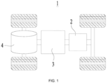
- the vehicle 1 may be a fuel vehicle, a gas vehicle, or a new energy vehicle
- the new energy vehicle may be a battery electric vehicle, a hybrid electric vehicle, an extended range vehicle, or the like.
- the vehicle 1 may be provided therein with a battery 2, a controller 3, and a motor 4, and the controller 3 is configured to control the battery 2 to supply power to the motor 4.
- the battery 2 may be provided at a bottom or front or rear of the vehicle 1.
- the battery 2 may be configured to supply power to the vehicle 1; for example, the battery 2 may be used as an operation power source of the vehicle 1 for a circuit system of the vehicle 1, for example, for work power demand in starting, navigation, and running of the vehicle 1. In another embodiment of the present application, the battery 2 may be used not only as the operation power source of the vehicle 1 but also as a driving power source of the vehicle 1, and replaces or partially replaces fuel oil or natural gas to provide driving power for the vehicle 1.
- the battery 2 refers to a single physical module including one or more battery cells 6 to provide a higher voltage and capacity.
- the battery 2 may include a plurality of battery cells 6.
- a number of the battery cells 6 and a connection condition between the battery cells 6 may be set according to requirements to meet different power requirements.
- the plurality of battery cells 6 may be connected in series or in parallel or in series and parallel, and the series and parallel connection refers to a mixture of series connection and parallel connection, such that the battery 2 has larger capacity or power.
- the plurality of battery cells 6 may be connected in series or in parallel or in series and parallel to form battery modules, and the plurality of battery modules may be connected in series or in parallel or in series and parallel to form the battery 2. That is, the plurality of battery cells 6 may directly constitute the battery 2, or may first constitute the battery modules, and then, the battery modules constitute the battery 2.
- the battery 2 further includes a battery box 5 (or called a cover), the battery box 5 has an accommodating space therein, and the plurality of battery cells 6 are accommodated in the accommodating space.
- the battery box 5 may include two parts which are referred to herein as a first part 51 and a second part 52 respectively, and reference is made to FIG. 2 and FIG. 3 which shows the first part 51 of the battery box 5.
- the first part 51 and the second part 52 may be connected by buckling, bonding, or the like, to form the accommodating space.
- the plurality of battery cells 6 are connected in parallel or in series or in series and parallel to be placed in the box 5 formed by connecting the first part 51 and the second part 52. Shapes of the first part 51 and the second part 52 may be determined according to a shape combined by the plurality of battery cells 6.
- the battery box 5 is configured to protect the at least one battery cell 6, so as to reduce an influence of liquid or other foreign matter outside the battery 2 on charging or discharging of the at least one battery cell 6.
- the battery cell 6 may have a shape of a cylinder, a flat body, a rectangular parallelepiped, or other shapes, which is not limited in the embodiment of the present application.
- a packaging manner of the battery cell 6 includes, but is not limited to, a cylindrical battery cell, a square battery cell, a pouch battery cell, or the like, which is not specifically limited in the embodiment of the present application.
- the battery 2 may include other structures which are not repeated herein.
- the battery 2 may further include a bus component.
- the bus component is configured to electrically connect the plurality of battery cells 6, for example, to connect the plurality of battery cells 6 in parallel or in series or in series and parallel.
- the bus component may achieve electric connection between the battery cells 6 by connecting electrode terminals of the battery cells 6.
- the bus component may be fixedly connected with the electrode terminals of the battery cells 6 by welding.
- the bus component may include a conductive mechanism, and electric energy generated by the plurality of battery cells 6 may be further guided out through the battery box 5 by the conductive mechanism.
- an embodiment of a first aspect of the present application provides a high voltage box 7.
- the high voltage box 7 includes a housing and a relay 72, the housing includes an upper housing 711 and a lower housing 712, and the upper housing 711 and the lower housing 712 are connected to form an accommodating space.
- the relay 72 is provided in the accommodating space, the relay 72 includes a conducting strip 721, and the conducting strip 721 is in contact with the lower housing 712.
- the upper housing 711 and the lower housing 712 are configured to form the accommodating space to accommodate components and parts in the high voltage box 7.
- the upper housing 711 and the lower housing 712 are configured to protect components and parts, such as the relay 72, or the like, so as to reduce an influence of external objects on the components and parts, such as the relay 72, or the like, in the high voltage box 7 and an influence of high voltage components and parts in the high voltage box 7 on other structures inside the battery 2.
- the lower housing 712 is further configured to be fixedly connected with the battery box 5 to fix the high voltage box 7 in the battery box 5.
- the upper housing 711 and the lower housing 712 may be made of plastic, metal, or the like, which is not limited in the present application.
- the relay 72 is provided in the housing of the high voltage box 7, and the conducting strip 721 of the relay 72 is an element for leading out a circuit inside the relay 72 and being connected with the outside.
- the high voltage box 7 may be provided in the battery box 5, and the lower housing 712 of the high voltage box 7 is fixedly connected with the battery box 5.
- the relay 72 is provided in the high voltage box 7, and the conducting strip 721 of the relay 72 is in direct contact with an inner side of the lower housing 712 of the high voltage box 7.
- heat generated by work of the relay 72 is transferred to the conducting strip 721 of the relay 72, and since the conducting strip 721 is in direct contact with the inner side of the lower housing 712, the heat in the conducting strip 721 may be directly transferred into the lower housing 712 and is rapidly transferred to the outside of the high voltage box 7 via the lower housing 712, thus reducing a probability of transferring and storing the heat inside the high voltage box 7.
- the heat generated by the relay 72 is rapidly dissipated via the conducting strip 721 and the lower housing 712, such that a heat dissipation efficiency of the high voltage box 7 may be improved, thereby reducing a probability of an overheating phenomenon, or the like, of the high voltage box 7, and improving the safety performance of the battery 2.
- the high voltage box 7 further includes a water cooling plate 73, the water cooling plate 73 is in contact with a side of the lower housing 712 away from the relay 72, the water cooling plate 73 includes at least one water cooling channel, and the water cooling plate 73 further includes a water inlet and a water outlet which are communicated with the at least one water cooling channel.
- the water cooling plate 73 may come into contact and be connected with the lower housing 712 of the high voltage box 7.
- the water cooling plate 73 is an assembly which may absorb the heat in the lower housing 712 to cool the lower housing 712 and the high voltage box 7.
- the water cooling plate 73 includes at least one water cooling channel, cooling water flows into the at least one water cooling channel through the water inlet in the water cooling plate 73, so as to absorb the heat transferred to the water cooling plate 73 from the high voltage box 7, and then, the cooling water after heat absorption flows out through the water outlet, thus cooling the high voltage box 7.
- the battery 2 may further include a battery water cooling plate configured to cool the battery module or battery cell 6, and the water cooling plate 73 in the embodiment of the present application and the battery water cooling plate may also have an integral structure, so as to reduce a space occupied by the high voltage box 7 and the water cooling plate 73 contained therein, and reduce structural complexity in the battery 2.
- the heat generated by the components and parts, such as the relay 72, or the like, in the high voltage box 7 is transferred via the lower housing 712 to the water cooling plate 73 contacting and connected with the lower housing 712, and then absorbed by the cooling water flowing in the water cooling plate 73; that is, the water cooling plate 73 may absorb the heat transferred to the lower housing 712 from the components and parts, such as the relay 72, or the like, so as to cool the high voltage box 7, thereby further improving the heat dissipation effect of the high voltage box 7 and the safety performance of the battery 2.
- the lower housing 712 includes a metal portion 7121 and a plastic portion 7122 which are integrally molded by injection.
- the metal portion 7121 and the plastic portion 7122 are both main components of the lower housing 712.
- the metal portion 7121 may be made of metal or alloy having a large heat conductivity coefficient and good thermal conductivity, such as copper, aluminum, or the like.
- the plastic portion 7122 may be made of an insulating material, such as rubber, plastic, or the like.
- the lower housing 712 has the metal portion 7121 therein, and since the metal portion 7121 has a large heat conductivity coefficient and good thermal conductivity, the heat generated in the high voltage box 7 may be quickly guided out via the metal portion 7121 and absorbed by the water cooling plate 73 being in contact with the metal portion 7121, which increases a heat transfer speed, thus further improving the heat dissipation effect of the high voltage box 7.
- the integral injection molded structure may not only save a space arrangement of the high voltage box 7, but also improve an assembly efficiency of the high voltage box 7.
- a side of the metal portion 7121 away from the relay 72 is exposed on a surface of the lower housing 712 and is in contact with the water cooling plate 73.
- the surface of the metal portion 7121 is exposed and directly contacts the water cooling plate 73; that is, the plastic portion 7122 is not provided between the metal portion 7121 and the water cooling plate 73, such that the heat generated in the high voltage box 7 may be quickly guided out via the metal portion 7121 and absorbed by the water cooling plate 73 contacting the metal portion 7121, and the heat conducted on the lower housing 712 of the high voltage box may be better transferred to the water cooling plate 73, thereby increasing the heat transfer speed and further improving the heat dissipation effect of the high voltage box 7.
- the high voltage box 7 further includes at least one heat conduction metal block 74, the at least one heat conduction metal block 74 is provided in the accommodating space, and the at least one heat conduction metal block 74 is connected with the conducting strip 721 and is in contact with the lower housing 712.
- the at least one heat conduction metal block 74 includes, but is not limited to, a metal block with a large heat conductivity coefficient and high thermal conductivity, such as an aluminum block, a copper block, or the like.
- the at least one heat conduction metal block 74 is configured to conduct and store heat energy.
- a shape of the at least one heat conduction metal block 74 includes, but is not limited to, a rectangle, or the like.
- the at least one heat conduction metal block 74 may be in locked connection with the conducting strip 721 of the relay 72.
- the at least one heat conduction metal block 74 is provided in the high voltage box 7, the at least one heat conduction metal block 74 is connected with the conducting strip 721, and the at least one heat conduction metal block 74 may store part of the heat energy emitted by the relay 72, thus further increasing a heat dissipation speed of the relay 72.
- the heat generated by the relay 72 may be transferred into the lower housing 712 via the at least one heat conduction metal block 74, such that the at least one heat conduction metal block 74 and the lower housing 712 of the high voltage box have a larger contact area, a heat dissipation area of the relay 72 is increased, a new path is provided for transfer of the heat of the relay 72 to the lower housing 712 of the high voltage box, and the heat energy stored in the at least one heat conduction metal block 74 and the heat energy transferred by the relay 72 may be better transferred to the lower housing 712, thus improving the heat dissipation efficiency of the high voltage box 7.
- the high voltage box 7 further includes a heat conduction pad 75 and a heat-conduction insulating film 76, the heat conduction pad 75 is provided between the lower housing 712 and the water cooling plate 73, and the heat-conduction insulating film 76 is provided between the heat conduction pad 75 and the water cooling plate 73.
- the heat conduction pad 75 is made of a high-performance gap-filling heat conduction material, and may be configured to form a heat transfer interface between the lower housing 712 and the water cooling plate 73, and fill a gap between the lower housing 712 of the high voltage box and the water cooling plate 73, so as to complete heat transfer between the lower housing 712 of the high voltage box and the water cooling plate 73.
- the heat-conduction insulating film 76 is an insulating component covering a surface of the water cooling plate 73 to transfer the heat to the water cooling plate 73 more quickly.
- the heat conduction pad 75 and the heat-conduction insulating film 76 may be made of a same material having both good thermal conductivity and an excellent insulating property, such as a silicone material which has both good thermal conductivity and an excellent insulating property and may meet most requirements for heat conduction and insulation.
- the materials of the heat conduction pad 75 and the heat-conduction insulating film 76 may be selected according to requirements, which is not limited in the embodiment of the present application.
- the heat conduction pad 75 may fill the gap between the lower housing 712 and the water cooling plate 73, so as to exhaust air between the lower housing 712 and the water cooling plate 73, such that the water cooling plate 73 more sufficiently contacts the lower housing 712, thereby improving the heat dissipation effect of the high voltage box 7.
- the heat conduction pad 75 is provided between the lower housing 712 and the water cooling plate 73, and may thus rapidly absorb the heat in the high voltage box 7 and rapidly transfer the heat to the water cooling plate 73, thus further improving the heat dissipation efficiency of the high voltage box 7.
- the heat-conduction insulating film 76 may reduce a probability that a current in the high voltage box 7 is transmitted to the water cooling plate 73 while guaranteeing the heat dissipation efficiency, thus improving safety of the high voltage box 7.
- a side of the metal portion 7121 close to the relay 72 includes at least one electric connection region 713, and the at least one electric connection region 713 is exposed on the surface of the lower housing 712.
- the electric connection region 713 is an electric connection plane of the lower housing 712, the electric connection region 713 may include a plurality of locking points 714 thereon, the locking points 714 are configured to fix the high voltage box 7 and other components and parts, and the locking points 714 are also exposed on the surface of the lower housing 712.
- the electric connection region 713 is exposed on the surface of the lower housing 712; that is, no plastic part exists on and shields the electric connection region 713, which facilitates connection between the lower housing 712 and the components and parts in the high voltage box 7, thus improving an efficiency of assembly between the lower housing 712 and the components and parts in the high voltage box.
- the electric connection region 713 is of a convex structure.
- the electric connection region 713 may be an electric connection plane formed after the metal portion 7121 is stamped or subjected to other processes to protrude towards the inside of the high voltage box 7.
- the electric connection region 713 is set to be of a convex structure, thus reducing requirements for flatness of a surface of the electric connection region 713, and after the electric connection region 713 contacts the components and parts in the high voltage box 7, reducing gaps between the electric connection region 713 and contact surfaces of the components and parts, and reducing a useless overlapping area in the high voltage box 7.
- the convex structure facilitates the connection between the electric connection region 713 and the components and parts in the high voltage box 7, thereby further improving the efficiency of assembly between the lower housing 712 and the components and parts of the high voltage box.
- a chamfered structure 715 is provided at an edge of at least one side of the electric connection region 713, and the chamfered structure 715 is provided with an insulating layer.
- the chamfered structure 715 is provided at the edge of the electric connection region 713, and in a pressing process of integral injection molding of the metal portion 7121 and the plastic portion 7122 of the lower housing 712, the chamfered structure 715 may reduce a probability of residual glue on the surface of the electric connection region 713, thereby reducing a probability that the connection of the lower housing 712 and the components and parts is influenced by the residual glue on the surface of the electric connection region 713.
- a size of the chamfered structure 715 may be set according to actual requirements and process precision, which is not limited in the present application.
- the chamfered structure 715 may have a size of C0.6. The inventor of the present application has actually verified that the chamfered structure 715 of C0.6 may meet requirements of a production process, and may also achieve a use effect required by the embodiment of the present application.
- the chamfered structure 715 may reduce requirements for manufacturing precision of the lower housing 712 and a manufacturing mold of the lower housing 712, thus simplifying production process flow of the lower housing 712.
- the insulating layer is provided on the chamfered structure 715 and may be covering rubber, thus reducing an influence of the manufacturing mold of the lower housing 712 on the surface of the electric connection region 713 in the pressing process, and also reducing a probability of mold damage in the pressing process.
- the chamfered structure 715 may be provided around an edge of the electric connection region 713.
- An embodiment of a second aspect of the present application provides a battery 2, including the high voltage box 7 according to any one of the above descriptions.
- the high voltage box 7 may be provided in a battery box 5, and the lower housing 712 of the high voltage box 7 is fixedly connected with the battery box 5.
- the relay 72 is provided in the high voltage box 7, and the conducting strip 721 of the relay 72 is in direct contact with an inner side of the lower housing 712 of the high voltage box 7.
- heat generated by work of the relay 72 is transferred to the conducting strip 721 of the relay 72, and since the conducting strip 721 is in direct contact with the inner side of the lower housing 712, the heat in the conducting strip 721 may be directly transferred into the lower housing 712 and is rapidly transferred to the outside of the high voltage box 7 via the lower housing 712, thus reducing a probability of transferring and storing the heat inside the high voltage box 7.
- the heat generated by the relay 72 is rapidly dissipated via the conducting strip 721 and the lower housing 712, such that a heat dissipation efficiency of the high voltage box 7 may be improved, thereby reducing a probability of an overheating phenomenon, or the like, of the high voltage box 7, and improving the safety performance of the battery 2.
- An embodiment of a third aspect of the present application provides an electric device, including the above-mentioned battery 2, the battery 2 being configured to supply electric energy to the electric device.
- the electric device since the electric device includes the above-mentioned battery 2, the electric device has all advantages of the above-mentioned battery 2.
- the electric device may be any of the above-mentioned apparatuses or systems in which the battery 2 is applied.
Landscapes
- Engineering & Computer Science (AREA)
- Chemical & Material Sciences (AREA)
- Chemical Kinetics & Catalysis (AREA)
- Electrochemistry (AREA)
- General Chemical & Material Sciences (AREA)
- Manufacturing & Machinery (AREA)
- Mechanical Engineering (AREA)
- Combustion & Propulsion (AREA)
- Transportation (AREA)
- Aviation & Aerospace Engineering (AREA)
- Physics & Mathematics (AREA)
- Thermal Sciences (AREA)
- Microelectronics & Electronic Packaging (AREA)
- Inorganic Chemistry (AREA)
- Battery Mounting, Suspending (AREA)
- Secondary Cells (AREA)
Abstract
Description
- The present application claims priority to
Chinese Patent Application No. 202122866340.0, entitled "High Voltage Box, Battery and Electric Device", filed on November 22, 2021 - The present application relates to the field of electrochemical device technologies, and particularly to a high voltage box, a battery and an electric device.
- In an electric device, such as an electric or hybrid vehicle, or the like, a high voltage box is a control unit for distributing energy of a power battery, and is configured to distribute a high voltage of the power battery. In a related art, the high voltage box usually has centralized design, and structural design is compact. In order to guarantee normal operation of the vehicle, the high voltage box is required to work in a vibration environment, a high and low temperature environment, a damp and hot environment, an environment with high power output, or the like. However, the existing high voltage box has a poor heat dissipation effect, such that the high voltage box has an overheating problem, or the like, thus influencing safety performances of the battery and the electric device.
- In view of the above-mentioned problems, an object of the embodiments of the present application is to provide a high voltage box, a battery and an electric device, so as to improve a heat dissipation effect of the high voltage box, thereby improving a safety performance of the battery. The specific technical solution is as follows.
- An embodiment of a first aspect of the present application provides a high voltage box, including: a housing and a relay, the housing including an upper housing and a lower housing, and the upper housing and the lower housing being connected to form an accommodating space; the relay being provided in the accommodating space, the relay including a conducting strip, and the conducting strip being in contact with the lower housing.
- In the technical solution of the embodiment of the present application, the high voltage box may be provided in a battery box, and the lower housing of the high voltage box is fixedly connected with the battery box. The relay is provided in the high voltage box, and the conducting strip of the relay is in direct contact with an inner side of the lower housing of the high voltage box. In a working process of the high voltage box, heat generated by work of the relay is transferred to the conducting strip of the relay, and since the conducting strip is in direct contact with the inner side of the lower housing, the heat in the conducting strip may be directly transferred into the lower housing and is rapidly transferred to the outside of the high voltage box via the lower housing, thus reducing a probability of transferring and storing the heat inside the high voltage box. The heat generated by the relay is rapidly dissipated via the conducting strip and the lower housing, such that a heat dissipation efficiency of the high voltage box may be improved, thereby reducing a probability of an overheating phenomenon, or the like, of the high voltage box, and improving the safety performance of the battery.
- In some embodiments, the high voltage box further includes a water cooling plate, the water cooling plate is in contact with one side of the lower housing away from the relay, the water cooling plate includes at least one water cooling channel, and the water cooling plate further includes a water inlet and a water outlet which are communicated with the at least one water cooling channel. Thus, the water cooling plate may absorb the heat transferred to the lower housing by components and parts, such as the relay, or the like, which may further improve the heat dissipation effect of the high voltage box, thereby further improving the safety performance of the battery.
- In some embodiments, the lower housing includes a metal portion and a plastic portion which are integrally molded by injection. Thus, the metal portion in the lower housing may more quickly absorb the heat generated by the components and parts, such as the relay, or the like, and transfer the heat away, thus further improving the heat dissipation effect of the high voltage box.
- In some embodiments, one side of the metal portion away from the relay is exposed on a surface of the lower housing and is in contact with the water cooling plate. Thus, the heat generated in the high voltage box may be quickly guided out via the metal portion and absorbed by the water cooling plate being in contact with the metal portion, which increases a heat transfer speed, thus further improving the heat dissipation effect of the high voltage box.
- In some embodiments, the high voltage box further includes at least one heat conduction metal block, the at least one heat conduction metal block is provided in the accommodating space, and the at least one heat conduction metal block is connected with the conducting strip and is in contact with the lower housing. The at least one heat conduction metal block is provided in the high voltage box to be connected with the conducting strip, such that part of heat energy emitted by the relay may be stored; the at least one heat conduction metal block further is in contact with the lower housing, such that the heat energy stored by the at least one heat conduction metal block and the heat energy transferred by the relay may be better transferred to the lower housing, thus improving the heat dissipation efficiency.
- In some embodiments, the high voltage box further includes a heat conduction pad and a heat-conduction insulating film, the heat conduction pad is provided between the lower housing and the water cooling plate, and the heat-conduction insulating film is provided between the heat conduction pad and the water cooling plate. Thus, the heat conduction pad may quickly absorb the heat in the high voltage box and quickly transfer the heat to the water cooling plate, thus further improving the heat dissipation efficiency of the high voltage box; the heat-conduction insulating film may reduce a probability that a current in the high voltage box is transmitted to the water cooling plate, thus improving safety of the high voltage box.
- In some embodiments, one side of the metal portion close to the relay includes at least one electric connection region, and the at least one electric connection region is exposed on the surface of the lower housing. The electric connection region is exposed and thus conveniently connected with the components and parts in the high voltage box, thereby improving an efficiency of assembly between the lower housing and the components and parts of the high voltage box.
- In some embodiments, the electric connection region is of a convex structure. The convex structure facilitates the connection between the electric connection region on the lower housing and the components and parts in the high voltage box, thereby further improving the efficiency of assembly between the lower housing and the components and parts of the high voltage box.
- In some embodiments, a chamfered structure is provided at an edge of at least one side of the electric connection region, and the chamfered structure is provided with an insulating layer. The chamfered structure may reduce a probability of residual glue on an electric connection surface, thereby reducing a probability that the connection of the lower housing and the components and parts is influenced by the residual glue on the electric connection surface. Furthermore, the chamfered structure may reduce requirements for manufacturing precision of the lower housing and a manufacturing mold of the lower housing, thus simplifying production process flow of the lower housing; the chamfered structure is provided with the insulating layer, thus reducing an influence of the manufacturing mold of the lower housing on the electric connection surface in a pressing process, and also reducing a probability of mold damage in the pressing process.
- An embodiment of a second aspect of the present application provides a battery, including the high voltage box according to any one of the above descriptions.
- An embodiment of a third aspect of the present application provides an electric device, including the above-mentioned battery, the battery being configured to supply electric energy to the electric device.
- Certainly, any product or method for implementing the present application does not necessarily achieve all the advantages described above at the same time. The foregoing description merely briefly describes the technical solution of the present application. To more clearly understand the technical means of the present application, the technical means of the present application can be implemented according to content of the specification. Moreover, to make the foregoing and other objectives, characteristics, and advantages of the present application more comprehensible, particular embodiments of the present application are described below.
- Various other advantages and merits will become apparent to those skilled in the art by reading through the following detailed description of preferred embodiments. Figures are only intended to illustrate preferred embodiments and not construed as limiting the present application. In all figures, like reference numerals denote like parts. In the drawings:
-
FIG. 1 is a schematic structural diagram of a vehicle according to some embodiments of the present application; -
FIG. 2 is a schematic exploded structural diagram of a battery according to some embodiments of the present application; -
FIG. 3 is a schematic internal structural diagram of a battery according to some embodiments of the present application; -
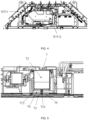
FIG. 4 is a partial top view of a battery box according to some embodiments of the present application; -
FIG. 5 is a sectional view of a high voltage box according to some embodiments of the present application; -
FIG. 6 is a partial top view of a battery box according to some embodiments of the present application; -
FIG. 7 is a schematic structural diagram of a lower housing of a high voltage box according to some embodiments of the present application; and -
FIG. 8 is an enlarged view of region A inFIG. 7 . - Reference numerals: 1-vehicle, 2-battery, 3-controller, 4-motor, 5-battery box, 6-battery cell, 7-high voltage box, 51-first part, 52-second part, 72-relay, 73-water cooling plate, 74-heat conduction metal block, 75-heat conduction pad, 76-heat-conduction insulating film, 711-upperhousing, 712-lower housing, 713-electric connection region, 714-locking point, 715-chamfered structure, 721-conducting strip, 7121-metal portion, and 7122-plastic portion.
- The embodiments of the technical solutions of the present application will be described in detail below with reference to the accompanying drawings. The following embodiments are only used to illustrate the technical solutions of the present application more clearly, and are therefore only used as examples, and cannot be used to limit the protection scope of the present application.
- Unless defined otherwise, all technical and scientific terms used herein have the same meanings as are commonly understood by those skilled in the art; the terms used herein are merely for the purpose of describing particular embodiments, and are not intended to limit the present application; the terms "including" and "having" and their any variations in the specification, claims and aforesaid figures of the present application are intended to cover non-exclusive inclusion.
- In the description of the embodiments of the present application, the technical terms such as "first", "second", or the like, are only used for distinguishing different objects, and are not intended to indicate or imply relative importance or significance or to imply the number, specific sequence or primary and secondary relationship of indicated technical features. In the description of the embodiments of the present application, "a plurality of" means more than two unless otherwise specified.
- The term "embodiment" mentioned herein is intended to mean that specific features, structures, or characteristics described in conjunction with the embodiments may be included in at least one embodiment of the present application. This term "embodiment" appearing at various places throughout the specification does not necessarily refer to the same embodiments, or independent or alternative embodiments that are mutually conflicting with other embodiments. Persons skilled in the art can explicitly and implicitly understand that the embodiments described herein may be combined with other embodiments.
- In the description of the embodiments of the present application, the term "and/or" herein only describes an association relationship between associated objects, and indicates that three relationships may exist. For example, A and/or B may indicate three cases: only A exists; both A and B exist; and only B exists. In addition, in this specification, the symbol "/" generally indicates that associated objects have a relationship of "or".
- In the description of the embodiments of the present application, the term "a plurality of" means more than two (including two); similarly, "a plurality of groups" means more than two groups (including two groups), and "a plurality of sheets" means more than two sheets (including two sheets).
- In the description of the embodiments of the present application, directions or positional relationships indicated by the technical terms "center", "longitudinal", "transverse", "length", "width", "thickness", "upper", "lower", "front", "rear", "left", "right", "vertical", "horizontal", "top", "bottom", "inner", "outer", "clockwise", "anticlockwise", "axial", "radial", "circumferential" etc. are based on orientations or positional relationships shown in the accompanying drawings, and they are used only for describing the embodiments of the present application and for description simplicity, but do not indicate or imply that an indicated device or element must have a specific orientation or be constructed and operated in a specific orientation. Therefore, it cannot be understood as a limitation on the embodiments of the present application.
- In the description of the embodiments of the present application, unless specified or limited otherwise, the technical terms "mounted", "connected", "coupled", and "fixed" and the like are used broadly, and may be, for example, fixed connection, detachable connection, or integral connection; may also be mechanical or electrical connection; may also be direct connection or indirect connection via intervening structures; may also be communication or an interaction relationship of two elements. Specific meanings of the above terms in the embodiments of the present application can be understood by those skilled in the art according to specific situations.
- A high voltage box includes components and parts, such as a fuse, a relay, a current sensor, a pre-charging resistor, or the like, and all the components and parts are provided in an accommodating space in the high voltage box. In order to guarantee normal operation of an electric device, such as an electric vehicle, or the like, the high voltage box is required to work in a vibration environment, a high and low temperature environment, a damp and hot environment, an environment with high power output, or the like. Furthermore, in order to reduce a space of the whole vehicle and connecting wiring harnesses to the maximum extent, and reduce a probability of thermal failure and other phenomena of the high voltage box or a battery, requirements exist for an arrangement scheme of the components and parts in the high voltage box, and the high voltage box is required to be equipped with a good heat dissipation system.
- In a related art, a heat dissipation performance of the high voltage box may be improved by increasing a cross-sectional area of a bus bar in the high voltage box. However, the increase of the cross-sectional area of the bus bar requires a greater space inside the high voltage box. In order to solve the above-mentioned problem, a housing of the high voltage box may be provided with heat dissipation holes, so as to improve the heat dissipation performance of the high voltage box while the space in the high voltage box is not influenced.
- However, the heat dissipation hole has a small improving effect on the heat dissipation performance of the high voltage box, and may also influence a safety performance of the battery with the high voltage box.
- Based on the above considerations, in order to improve a heat dissipation effect of the high voltage box and the safety performance of the battery, the inventor has designed a high voltage box after in-depth research, i.e., the high voltage box according to the present application. By inverting a relay in the high voltage box, a conducting strip on the relay is in contact with a lower housing of the high voltage box, such that heat generated in a working process of the relay may be directly transferred to the lower housing of the high voltage box through the conducting strip, thereby improving a heat dissipation capability of the high voltage box, and improving the safety performance of the battery.
- An embodiment of the present application provides an electric device with the battery including the above-mentioned high voltage box as a power source, and the electric device may be, but is not limited to, a mobile phone, a portable apparatus, a notebook computer, a battery car, an electric vehicle, a ship, a spacecraft, an electric toy, an electric tool, or the like; for example, the spacecraft includes an airplane, a rocket, a space shuttle, a spaceship, or the like; the electric toy includes a stationary or movable electric toy, for example, a game machine, an electric car toy, an electric ship toy, an electric airplane toy, or the like; the electric tool includes a metal cutting electric tool, a grinding electric tool, an assembly electric tool, and an electric tool for railways, for example, an electric drill, an electric grinder, an electric wrench, an electric screwdriver, an electric hammer, an electric impact drill, a concrete vibrator, and an electric planer.
- The battery described in the embodiment of the present application is not limited to application to the above-described electric device, but may be applied to all devices in which batteries are used, and for simplicity of description, the following embodiments are all described with an electric vehicle as an example.
- For example, referring to
FIG. 1 which is a schematic structural diagram of avehicle 1 according to an embodiment of the present application, thevehicle 1 may be a fuel vehicle, a gas vehicle, or a new energy vehicle, and the new energy vehicle may be a battery electric vehicle, a hybrid electric vehicle, an extended range vehicle, or the like. Thevehicle 1 may be provided therein with abattery 2, acontroller 3, and amotor 4, and thecontroller 3 is configured to control thebattery 2 to supply power to themotor 4. For example, thebattery 2 may be provided at a bottom or front or rear of thevehicle 1. Thebattery 2 may be configured to supply power to thevehicle 1; for example, thebattery 2 may be used as an operation power source of thevehicle 1 for a circuit system of thevehicle 1, for example, for work power demand in starting, navigation, and running of thevehicle 1. In another embodiment of the present application, thebattery 2 may be used not only as the operation power source of thevehicle 1 but also as a driving power source of thevehicle 1, and replaces or partially replaces fuel oil or natural gas to provide driving power for thevehicle 1. - The
battery 2 according to the embodiment of the present application refers to a single physical module including one ormore battery cells 6 to provide a higher voltage and capacity. Referring toFIG. 2 , thebattery 2 may include a plurality ofbattery cells 6. A number of thebattery cells 6 and a connection condition between thebattery cells 6 may be set according to requirements to meet different power requirements. Specifically, the plurality ofbattery cells 6 may be connected in series or in parallel or in series and parallel, and the series and parallel connection refers to a mixture of series connection and parallel connection, such that thebattery 2 has larger capacity or power. Optionally, the plurality ofbattery cells 6 may be connected in series or in parallel or in series and parallel to form battery modules, and the plurality of battery modules may be connected in series or in parallel or in series and parallel to form thebattery 2. That is, the plurality ofbattery cells 6 may directly constitute thebattery 2, or may first constitute the battery modules, and then, the battery modules constitute thebattery 2. - The
battery 2 further includes a battery box 5 (or called a cover), thebattery box 5 has an accommodating space therein, and the plurality ofbattery cells 6 are accommodated in the accommodating space. As shown inFIG. 2 , thebattery box 5 may include two parts which are referred to herein as afirst part 51 and asecond part 52 respectively, and reference is made toFIG. 2 and FIG. 3 which shows thefirst part 51 of thebattery box 5. Thefirst part 51 and thesecond part 52 may be connected by buckling, bonding, or the like, to form the accommodating space. The plurality ofbattery cells 6 are connected in parallel or in series or in series and parallel to be placed in thebox 5 formed by connecting thefirst part 51 and thesecond part 52. Shapes of thefirst part 51 and thesecond part 52 may be determined according to a shape combined by the plurality ofbattery cells 6. - The
battery box 5 is configured to protect the at least onebattery cell 6, so as to reduce an influence of liquid or other foreign matter outside thebattery 2 on charging or discharging of the at least onebattery cell 6. Thebattery cell 6 may have a shape of a cylinder, a flat body, a rectangular parallelepiped, or other shapes, which is not limited in the embodiment of the present application. A packaging manner of thebattery cell 6 includes, but is not limited to, a cylindrical battery cell, a square battery cell, a pouch battery cell, or the like, which is not specifically limited in the embodiment of the present application. - Furthermore, the
battery 2 may include other structures which are not repeated herein. For example, thebattery 2 may further include a bus component. The bus component is configured to electrically connect the plurality ofbattery cells 6, for example, to connect the plurality ofbattery cells 6 in parallel or in series or in series and parallel. Specifically, the bus component may achieve electric connection between thebattery cells 6 by connecting electrode terminals of thebattery cells 6. Further, the bus component may be fixedly connected with the electrode terminals of thebattery cells 6 by welding. Optionally, the bus component may include a conductive mechanism, and electric energy generated by the plurality ofbattery cells 6 may be further guided out through thebattery box 5 by the conductive mechanism. - According to some embodiments of the present application, referring to
FIGS. 3 to 5 , an embodiment of a first aspect of the present application provides ahigh voltage box 7. Thehigh voltage box 7 includes a housing and arelay 72, the housing includes anupper housing 711 and alower housing 712, and theupper housing 711 and thelower housing 712 are connected to form an accommodating space. Therelay 72 is provided in the accommodating space, therelay 72 includes a conductingstrip 721, and the conductingstrip 721 is in contact with thelower housing 712. - In the embodiment of the present application, the
upper housing 711 and thelower housing 712 are configured to form the accommodating space to accommodate components and parts in thehigh voltage box 7. Theupper housing 711 and thelower housing 712 are configured to protect components and parts, such as therelay 72, or the like, so as to reduce an influence of external objects on the components and parts, such as therelay 72, or the like, in thehigh voltage box 7 and an influence of high voltage components and parts in thehigh voltage box 7 on other structures inside thebattery 2. Furthermore, as shown inFIGS. 3 and4 , thelower housing 712 is further configured to be fixedly connected with thebattery box 5 to fix thehigh voltage box 7 in thebattery box 5. Theupper housing 711 and thelower housing 712 may be made of plastic, metal, or the like, which is not limited in the present application. - The
relay 72 is provided in the housing of thehigh voltage box 7, and the conductingstrip 721 of therelay 72 is an element for leading out a circuit inside therelay 72 and being connected with the outside. - In the technical solution of the embodiment of the present application, as shown in
FIGS. 4 and 5 , thehigh voltage box 7 may be provided in thebattery box 5, and thelower housing 712 of thehigh voltage box 7 is fixedly connected with thebattery box 5. Therelay 72 is provided in thehigh voltage box 7, and the conductingstrip 721 of therelay 72 is in direct contact with an inner side of thelower housing 712 of thehigh voltage box 7. In a working process of thehigh voltage box 7, heat generated by work of therelay 72 is transferred to the conductingstrip 721 of therelay 72, and since the conductingstrip 721 is in direct contact with the inner side of thelower housing 712, the heat in the conductingstrip 721 may be directly transferred into thelower housing 712 and is rapidly transferred to the outside of thehigh voltage box 7 via thelower housing 712, thus reducing a probability of transferring and storing the heat inside thehigh voltage box 7. The heat generated by therelay 72 is rapidly dissipated via the conductingstrip 721 and thelower housing 712, such that a heat dissipation efficiency of thehigh voltage box 7 may be improved, thereby reducing a probability of an overheating phenomenon, or the like, of thehigh voltage box 7, and improving the safety performance of thebattery 2. - According to some embodiments of the present application, referring to
FIG. 5 , thehigh voltage box 7 further includes awater cooling plate 73, thewater cooling plate 73 is in contact with a side of thelower housing 712 away from therelay 72, thewater cooling plate 73 includes at least one water cooling channel, and thewater cooling plate 73 further includes a water inlet and a water outlet which are communicated with the at least one water cooling channel. - In the embodiment of the present application, as shown in
FIG. 5 , thewater cooling plate 73 may come into contact and be connected with thelower housing 712 of thehigh voltage box 7. Thewater cooling plate 73 is an assembly which may absorb the heat in thelower housing 712 to cool thelower housing 712 and thehigh voltage box 7. Thewater cooling plate 73 includes at least one water cooling channel, cooling water flows into the at least one water cooling channel through the water inlet in thewater cooling plate 73, so as to absorb the heat transferred to thewater cooling plate 73 from thehigh voltage box 7, and then, the cooling water after heat absorption flows out through the water outlet, thus cooling thehigh voltage box 7. Further, thebattery 2 may further include a battery water cooling plate configured to cool the battery module orbattery cell 6, and thewater cooling plate 73 in the embodiment of the present application and the battery water cooling plate may also have an integral structure, so as to reduce a space occupied by thehigh voltage box 7 and thewater cooling plate 73 contained therein, and reduce structural complexity in thebattery 2. - In the embodiment of the present application, after transferred to the
lower housing 712, the heat generated by the components and parts, such as therelay 72, or the like, in thehigh voltage box 7 is transferred via thelower housing 712 to thewater cooling plate 73 contacting and connected with thelower housing 712, and then absorbed by the cooling water flowing in thewater cooling plate 73; that is, thewater cooling plate 73 may absorb the heat transferred to thelower housing 712 from the components and parts, such as therelay 72, or the like, so as to cool thehigh voltage box 7, thereby further improving the heat dissipation effect of thehigh voltage box 7 and the safety performance of thebattery 2. - According to some embodiments of the present application, referring to
FIG. 7 , thelower housing 712 includes ametal portion 7121 and aplastic portion 7122 which are integrally molded by injection. - In the embodiment of the present application, the
metal portion 7121 and theplastic portion 7122 are both main components of thelower housing 712. Themetal portion 7121 may be made of metal or alloy having a large heat conductivity coefficient and good thermal conductivity, such as copper, aluminum, or the like. Theplastic portion 7122 may be made of an insulating material, such as rubber, plastic, or the like. - In the embodiment of the present application, the
lower housing 712 has themetal portion 7121 therein, and since themetal portion 7121 has a large heat conductivity coefficient and good thermal conductivity, the heat generated in thehigh voltage box 7 may be quickly guided out via themetal portion 7121 and absorbed by thewater cooling plate 73 being in contact with themetal portion 7121, which increases a heat transfer speed, thus further improving the heat dissipation effect of thehigh voltage box 7. The integral injection molded structure may not only save a space arrangement of thehigh voltage box 7, but also improve an assembly efficiency of thehigh voltage box 7. - According to some embodiments of the present application, referring to
FIG. 7 , a side of themetal portion 7121 away from therelay 72 is exposed on a surface of thelower housing 712 and is in contact with thewater cooling plate 73. - In the embodiment of the present application, the surface of the
metal portion 7121 is exposed and directly contacts thewater cooling plate 73; that is, theplastic portion 7122 is not provided between themetal portion 7121 and thewater cooling plate 73, such that the heat generated in thehigh voltage box 7 may be quickly guided out via themetal portion 7121 and absorbed by thewater cooling plate 73 contacting themetal portion 7121, and the heat conducted on thelower housing 712 of the high voltage box may be better transferred to thewater cooling plate 73, thereby increasing the heat transfer speed and further improving the heat dissipation effect of thehigh voltage box 7. - According to some embodiments of the present application, referring to
FIG. 5 , thehigh voltage box 7 further includes at least one heatconduction metal block 74, the at least one heatconduction metal block 74 is provided in the accommodating space, and the at least one heatconduction metal block 74 is connected with the conductingstrip 721 and is in contact with thelower housing 712. - In the embodiment of the present application, the at least one heat
conduction metal block 74 includes, but is not limited to, a metal block with a large heat conductivity coefficient and high thermal conductivity, such as an aluminum block, a copper block, or the like. The at least one heatconduction metal block 74 is configured to conduct and store heat energy. A shape of the at least one heatconduction metal block 74 includes, but is not limited to, a rectangle, or the like. The at least one heatconduction metal block 74 may be in locked connection with the conductingstrip 721 of therelay 72. - In the embodiment of the present application, the at least one heat
conduction metal block 74 is provided in thehigh voltage box 7, the at least one heatconduction metal block 74 is connected with the conductingstrip 721, and the at least one heatconduction metal block 74 may store part of the heat energy emitted by therelay 72, thus further increasing a heat dissipation speed of therelay 72. Furthermore, since the at least one heatconduction metal block 74 contacts both the conductingstrip 721 of therelay 72 and thelower housing 712, the heat generated by therelay 72 may be transferred into thelower housing 712 via the at least one heatconduction metal block 74, such that the at least one heatconduction metal block 74 and thelower housing 712 of the high voltage box have a larger contact area, a heat dissipation area of therelay 72 is increased, a new path is provided for transfer of the heat of therelay 72 to thelower housing 712 of the high voltage box, and the heat energy stored in the at least one heatconduction metal block 74 and the heat energy transferred by therelay 72 may be better transferred to thelower housing 712, thus improving the heat dissipation efficiency of thehigh voltage box 7. - According to some embodiments of the present application, referring to
FIGS. 5 and6 , thehigh voltage box 7 further includes aheat conduction pad 75 and a heat-conduction insulating film 76, theheat conduction pad 75 is provided between thelower housing 712 and thewater cooling plate 73, and the heat-conduction insulating film 76 is provided between theheat conduction pad 75 and thewater cooling plate 73. - In the embodiment of the present application, the
heat conduction pad 75 is made of a high-performance gap-filling heat conduction material, and may be configured to form a heat transfer interface between thelower housing 712 and thewater cooling plate 73, and fill a gap between thelower housing 712 of the high voltage box and thewater cooling plate 73, so as to complete heat transfer between thelower housing 712 of the high voltage box and thewater cooling plate 73. The heat-conduction insulating film 76 is an insulating component covering a surface of thewater cooling plate 73 to transfer the heat to thewater cooling plate 73 more quickly. Theheat conduction pad 75 and the heat-conduction insulating film 76 may be made of a same material having both good thermal conductivity and an excellent insulating property, such as a silicone material which has both good thermal conductivity and an excellent insulating property and may meet most requirements for heat conduction and insulation. The materials of theheat conduction pad 75 and the heat-conduction insulating film 76 may be selected according to requirements, which is not limited in the embodiment of the present application. - In the embodiment of the present application, the
heat conduction pad 75 may fill the gap between thelower housing 712 and thewater cooling plate 73, so as to exhaust air between thelower housing 712 and thewater cooling plate 73, such that thewater cooling plate 73 more sufficiently contacts thelower housing 712, thereby improving the heat dissipation effect of thehigh voltage box 7. Theheat conduction pad 75 is provided between thelower housing 712 and thewater cooling plate 73, and may thus rapidly absorb the heat in thehigh voltage box 7 and rapidly transfer the heat to thewater cooling plate 73, thus further improving the heat dissipation efficiency of thehigh voltage box 7. The heat-conduction insulating film 76 may reduce a probability that a current in thehigh voltage box 7 is transmitted to thewater cooling plate 73 while guaranteeing the heat dissipation efficiency, thus improving safety of thehigh voltage box 7. - According to some embodiments of the present application, referring to
FIGS. 7 and8 , a side of themetal portion 7121 close to therelay 72 includes at least oneelectric connection region 713, and the at least oneelectric connection region 713 is exposed on the surface of thelower housing 712. - In the embodiment of the present application, the
electric connection region 713 is an electric connection plane of thelower housing 712, theelectric connection region 713 may include a plurality of lockingpoints 714 thereon, the locking points 714 are configured to fix thehigh voltage box 7 and other components and parts, and the locking points 714 are also exposed on the surface of thelower housing 712. - In the embodiment of the present application, the
electric connection region 713 is exposed on the surface of thelower housing 712; that is, no plastic part exists on and shields theelectric connection region 713, which facilitates connection between thelower housing 712 and the components and parts in thehigh voltage box 7, thus improving an efficiency of assembly between thelower housing 712 and the components and parts in the high voltage box. - According to some embodiments of the present application, referring to
FIGS. 7 and8 , theelectric connection region 713 is of a convex structure. - In the embodiment of the present application, as shown in
FIGS. 6 and8 , theelectric connection region 713 may be an electric connection plane formed after themetal portion 7121 is stamped or subjected to other processes to protrude towards the inside of thehigh voltage box 7. Theelectric connection region 713 is set to be of a convex structure, thus reducing requirements for flatness of a surface of theelectric connection region 713, and after theelectric connection region 713 contacts the components and parts in thehigh voltage box 7, reducing gaps between theelectric connection region 713 and contact surfaces of the components and parts, and reducing a useless overlapping area in thehigh voltage box 7. The convex structure facilitates the connection between theelectric connection region 713 and the components and parts in thehigh voltage box 7, thereby further improving the efficiency of assembly between thelower housing 712 and the components and parts of the high voltage box. - According to some embodiments of the present application, referring to
FIG. 8 , achamfered structure 715 is provided at an edge of at least one side of theelectric connection region 713, and the chamferedstructure 715 is provided with an insulating layer. - In the embodiment of the present application, the chamfered
structure 715 is provided at the edge of theelectric connection region 713, and in a pressing process of integral injection molding of themetal portion 7121 and theplastic portion 7122 of thelower housing 712, the chamferedstructure 715 may reduce a probability of residual glue on the surface of theelectric connection region 713, thereby reducing a probability that the connection of thelower housing 712 and the components and parts is influenced by the residual glue on the surface of theelectric connection region 713. A size of the chamferedstructure 715 may be set according to actual requirements and process precision, which is not limited in the present application. For example, the chamferedstructure 715 may have a size of C0.6. The inventor of the present application has actually verified that the chamferedstructure 715 of C0.6 may meet requirements of a production process, and may also achieve a use effect required by the embodiment of the present application. - Furthermore, the chamfered
structure 715 may reduce requirements for manufacturing precision of thelower housing 712 and a manufacturing mold of thelower housing 712, thus simplifying production process flow of thelower housing 712. The insulating layer is provided on the chamferedstructure 715 and may be covering rubber, thus reducing an influence of the manufacturing mold of thelower housing 712 on the surface of theelectric connection region 713 in the pressing process, and also reducing a probability of mold damage in the pressing process. Further, as shown inFIG. 8 , the chamferedstructure 715 may be provided around an edge of theelectric connection region 713. - An embodiment of a second aspect of the present application provides a
battery 2, including thehigh voltage box 7 according to any one of the above descriptions. - In the
high voltage box 7 of thebattery 2 in the technical solution of the embodiment of the present application, thehigh voltage box 7 may be provided in abattery box 5, and thelower housing 712 of thehigh voltage box 7 is fixedly connected with thebattery box 5. Therelay 72 is provided in thehigh voltage box 7, and the conductingstrip 721 of therelay 72 is in direct contact with an inner side of thelower housing 712 of thehigh voltage box 7. In a working process of thehigh voltage box 7, heat generated by work of therelay 72 is transferred to the conductingstrip 721 of therelay 72, and since the conductingstrip 721 is in direct contact with the inner side of thelower housing 712, the heat in the conductingstrip 721 may be directly transferred into thelower housing 712 and is rapidly transferred to the outside of thehigh voltage box 7 via thelower housing 712, thus reducing a probability of transferring and storing the heat inside thehigh voltage box 7. The heat generated by therelay 72 is rapidly dissipated via the conductingstrip 721 and thelower housing 712, such that a heat dissipation efficiency of thehigh voltage box 7 may be improved, thereby reducing a probability of an overheating phenomenon, or the like, of thehigh voltage box 7, and improving the safety performance of thebattery 2. - An embodiment of a third aspect of the present application provides an electric device, including the above-mentioned
battery 2, thebattery 2 being configured to supply electric energy to the electric device. - In the electric device in the technical solution of the embodiment of the present application, since the electric device includes the above-mentioned
battery 2, the electric device has all advantages of the above-mentionedbattery 2. The electric device may be any of the above-mentioned apparatuses or systems in which thebattery 2 is applied. - Finally, it should be noted that the above embodiments are only used to illustrate the technical solutions of the present application, not to limit the present application; although the present application is described in detail with reference to the above embodiments, those having ordinary skill in the art should understand that they still can modify technical solutions recited in the aforesaid embodiments or equivalently replace partial or all technical features therein; these modifications or substitutions do not make essence of corresponding technical solutions depart from the scope of technical solutions of embodiments of the present application, and all of them should be included in the scope of the claims and description of the present application. Particularly, as long as structural conflicts do not exist, all technical features mentioned in all the embodiments may be combined together in any mode. The present application is not limited to the specific embodiments disclosed in the description, but includes all technical solutions falling into the scope of the claims.
Claims (11)
- A high voltage box, characterized by comprising:a housing, comprising an upper housing and a lower housing, the upper housing and the lower housing being connected to form an accommodating space; anda relay, provided in the accommodating space, the relay comprising a conducting strip, and the conducting strip being in contact with the lower housing.
- The high voltage box according to claim 1, further comprising a water cooling plate, wherein the water cooling plate is in contact with one side of the lower housing away from the relay, the water cooling plate comprises at least one water cooling channel, and the water cooling plate further comprises a water inlet and a water outlet which are communicated with the at least one water cooling channel.
- The high voltage box according to claim 2, wherein the lower housing comprises a metal portion and a plastic portion which are integrally molded by injection.
- The high voltage box according to claim 3, wherein one side of the metal portion away from the relay is exposed on a surface of the lower housing and is in contact with the water cooling plate.
- The high voltage box according to claim 1, further comprising at least one heat conduction metal block, wherein the at least one heat conduction metal block is provided in the accommodating space, and the at least one heat conduction metal block is connected with the conducting strip and is in contact with the lower housing.
- The high voltage box according to claim 3, further comprising a heat conduction pad and a heat-conduction insulating film, wherein the heat conduction pad is provided between the lower housing and the water cooling plate, and the heat-conduction insulating film is provided between the heat conduction pad and the water cooling plate.
- The high voltage box according to claim 3, wherein one side of the metal portion close to the relay comprises at least one electric connection region, and the at least one electric connection region is exposed on a surface of the lower housing.
- The high voltage box according to claim 7, wherein the electric connection region is of a convex structure.
- The high voltage box according to claim 8, wherein a chamfered structure is provided at an edge of at least one side of the electric connection region, and the chamfered structure is provided with an insulating layer.
- A battery, characterized by comprising the high voltage box according to any one of claims 1 to 9.
- An electric device, characterized by comprising the battery according to claim 10, the battery being configured to supply electric energy to the electric device.
Applications Claiming Priority (2)
| Application Number | Priority Date | Filing Date | Title |
|---|---|---|---|
| CN202122866340.0U CN216251008U (en) | 2021-11-22 | 2021-11-22 | A high-voltage box, battery and electrical device |
| PCT/CN2022/093966 WO2023087643A1 (en) | 2021-11-22 | 2022-05-19 | High-voltage box, battery and electrical device |
Publications (2)
| Publication Number | Publication Date |
|---|---|
| EP4207471A1 true EP4207471A1 (en) | 2023-07-05 |
| EP4207471A4 EP4207471A4 (en) | 2023-10-25 |
Family
ID=80954859
Family Applications (1)
| Application Number | Title | Priority Date | Filing Date |
|---|---|---|---|
| EP22754755.1A Pending EP4207471A4 (en) | 2021-11-22 | 2022-05-19 | HIGH VOLTAGE BOX, BATTERY AND ELECTRICAL DEVICE |
Country Status (5)
| Country | Link |
|---|---|
| EP (1) | EP4207471A4 (en) |
| JP (1) | JP7510511B2 (en) |
| KR (1) | KR102874559B1 (en) |
| CN (1) | CN216251008U (en) |
| WO (1) | WO2023087643A1 (en) |
Cited By (1)
| Publication number | Priority date | Publication date | Assignee | Title |
|---|---|---|---|---|
| MA65147A1 (en) * | 2024-04-04 | 2025-10-31 | Université Internationale de RABAT | Device and method for preventing ignition and reducing maintenance costs in MV and HV electrical circuits |
Families Citing this family (8)
| Publication number | Priority date | Publication date | Assignee | Title |
|---|---|---|---|---|
| CN216251008U (en) * | 2021-11-22 | 2022-04-08 | 宁德时代新能源科技股份有限公司 | A high-voltage box, battery and electrical device |
| KR20240091166A (en) * | 2022-06-29 | 2024-06-21 | 컨템포러리 엠퍼렉스 테크놀로지 씨오., 리미티드 | Case, battery and electrical devices |
| CN115663331A (en) * | 2022-09-09 | 2023-01-31 | 广汽埃安新能源汽车有限公司 | Battery pack box structure, battery pack and electrical device |
| CN119069891A (en) * | 2023-05-31 | 2024-12-03 | 宁德时代新能源科技股份有限公司 | Batteries and electrical devices |
| CN116620114B (en) * | 2023-07-21 | 2024-01-02 | 宁德时代新能源科技股份有限公司 | High-voltage box, battery pack, electric control system and electricity utilization device |
| CN117198813B (en) * | 2023-08-14 | 2025-01-21 | 浙江富特科技股份有限公司 | Active heat dissipation structure of relay, high voltage distribution box and fast charging circuit |
| CN120601211A (en) * | 2024-03-05 | 2025-09-05 | 宁德时代新能源科技股份有限公司 | High-voltage box housing structure, high-voltage box, battery and electrical equipment |
| CN222803242U (en) * | 2024-03-16 | 2025-04-25 | 武汉亿纬储能有限公司 | High-voltage control box and energy storage system |
Family Cites Families (12)
| Publication number | Priority date | Publication date | Assignee | Title |
|---|---|---|---|---|
| JP5047827B2 (en) * | 2008-01-31 | 2012-10-10 | 矢崎総業株式会社 | Electrical junction box |
| WO2018105610A1 (en) * | 2016-12-05 | 2018-06-14 | トヨタ自動車株式会社 | Relay unit |
| CN207637716U (en) * | 2017-11-15 | 2018-07-20 | 惠州市亿纬新能源研究院 | One kind is across the two circuit magnetic latching relay of group formula |
| CN111354602A (en) * | 2018-12-20 | 2020-06-30 | 徐州翼鹄航空科技有限公司 | Relay capable of radiating heat |
| JP7078757B2 (en) * | 2019-01-10 | 2022-05-31 | ビークルエナジージャパン株式会社 | Battery pack |
| CN210129503U (en) * | 2019-07-31 | 2020-03-06 | 宁德时代新能源科技股份有限公司 | High-voltage box |
| CN210926231U (en) * | 2019-12-20 | 2020-07-03 | 孚能科技(镇江)有限公司 | A heat radiation structure and car for battery package |
| CN211931142U (en) | 2020-04-16 | 2020-11-13 | 宁德时代新能源科技股份有限公司 | High voltage boxes, battery packs and devices |
| JP2021180233A (en) * | 2020-05-13 | 2021-11-18 | 株式会社オートネットワーク技術研究所 | Circuit unit |
| CN212587616U (en) * | 2020-07-29 | 2021-02-23 | 孚能科技(赣州)股份有限公司 | High voltage boxes, battery packs and electric vehicles |
| CN214013023U (en) * | 2020-12-30 | 2021-08-20 | 蜂巢能源科技有限公司 | Power battery pack and vehicle with the same |
| CN216251008U (en) * | 2021-11-22 | 2022-04-08 | 宁德时代新能源科技股份有限公司 | A high-voltage box, battery and electrical device |
-
2021
- 2021-11-22 CN CN202122866340.0U patent/CN216251008U/en active Active
-
2022
- 2022-05-19 EP EP22754755.1A patent/EP4207471A4/en active Pending
- 2022-05-19 WO PCT/CN2022/093966 patent/WO2023087643A1/en not_active Ceased
- 2022-05-19 KR KR1020227029386A patent/KR102874559B1/en active Active
- 2022-05-19 JP JP2022551052A patent/JP7510511B2/en active Active
Cited By (1)
| Publication number | Priority date | Publication date | Assignee | Title |
|---|---|---|---|---|
| MA65147A1 (en) * | 2024-04-04 | 2025-10-31 | Université Internationale de RABAT | Device and method for preventing ignition and reducing maintenance costs in MV and HV electrical circuits |
Also Published As
| Publication number | Publication date |
|---|---|
| US20230275282A1 (en) | 2023-08-31 |
| JP7510511B2 (en) | 2024-07-03 |
| EP4207471A4 (en) | 2023-10-25 |
| JP2023554204A (en) | 2023-12-27 |
| WO2023087643A1 (en) | 2023-05-25 |
| CN216251008U (en) | 2022-04-08 |
| KR102874559B1 (en) | 2025-10-21 |
| KR20230076119A (en) | 2023-05-31 |
Similar Documents
| Publication | Publication Date | Title |
|---|---|---|
| EP4207471A1 (en) | High-voltage box, battery and electrical device | |
| KR102894252B1 (en) | End cap assembly, battery cell, battery and device using battery | |
| US20220352573A1 (en) | Battery cell, battery, power consumption device, and battery manufacturing method and device | |
| KR20210065268A (en) | Busbar Frame Assembly and Battery module including the same | |
| EP4274011B1 (en) | Box body of battery, battery, and electrical device | |
| CN216389518U (en) | Battery cell, battery and power consumption device | |
| US20240055693A1 (en) | Battery cell, battery, power consuming apparatus, and method and apparatus for manufacturing battery cell | |
| WO2023185244A1 (en) | Heat dissipation structure, high voltage box, battery, and electrical device | |
| WO2023134110A1 (en) | Battery and electric device | |
| WO2023134107A1 (en) | Battery and electric device | |
| EP4266464A1 (en) | Battery, electric device, and method and device for preparing battery | |
| CN220456515U (en) | Battery monomer, battery and power consumption device | |
| US20250337225A1 (en) | Power distribution apparatus, battery, and power consuming device | |
| US12620648B2 (en) | High voltage box, battery and electric device | |
| CN220710519U (en) | Battery module, battery and power-consuming device | |
| US20230198109A1 (en) | Battery cell, battery, electrical device, and method and apparatus for manufacturing battery cell | |
| CN114823249B (en) | Cooling device, high-voltage box, battery and power consumption device | |
| WO2024244397A1 (en) | Battery and electric device | |
| EP4258437B1 (en) | Battery and electric device | |
| KR20250007605A (en) | Batteries and electrical devices | |
| CN119318060A (en) | Batteries and electrical devices | |
| CN223583176U (en) | Battery device, electric equipment and energy storage device | |
| CN223260779U (en) | Battery device and electricity utilization device | |
| CN222775552U (en) | Battery devices and electrical equipment | |
| EP4243158A1 (en) | Battery and electric device |
Legal Events
| Date | Code | Title | Description |
|---|---|---|---|
| STAA | Information on the status of an ep patent application or granted ep patent |
Free format text: STATUS: UNKNOWN |
|
| STAA | Information on the status of an ep patent application or granted ep patent |
Free format text: STATUS: THE INTERNATIONAL PUBLICATION HAS BEEN MADE |
|
| PUAI | Public reference made under article 153(3) epc to a published international application that has entered the european phase |
Free format text: ORIGINAL CODE: 0009012 |
|
| STAA | Information on the status of an ep patent application or granted ep patent |
Free format text: STATUS: REQUEST FOR EXAMINATION WAS MADE |
|
| 17P | Request for examination filed |
Effective date: 20220825 |
|
| AK | Designated contracting states |
Kind code of ref document: A1 Designated state(s): AL AT BE BG CH CY CZ DE DK EE ES FI FR GB GR HR HU IE IS IT LI LT LU LV MC MK MT NL NO PL PT RO RS SE SI SK SM TR |
|
| A4 | Supplementary search report drawn up and despatched |
Effective date: 20230922 |
|
| RIC1 | Information provided on ipc code assigned before grant |
Ipc: H01M 50/574 20210101ALI20230918BHEP Ipc: H01M 50/249 20210101ALI20230918BHEP Ipc: H01M 50/209 20210101ALI20230918BHEP Ipc: H01M 10/667 20140101ALI20230918BHEP Ipc: H01M 10/6556 20140101ALI20230918BHEP Ipc: H01M 10/643 20140101ALI20230918BHEP Ipc: H01M 10/625 20140101ALI20230918BHEP Ipc: H01M 10/613 20140101ALI20230918BHEP Ipc: H01M 50/50 20210101AFI20230918BHEP |
|
| RAP1 | Party data changed (applicant data changed or rights of an application transferred) |
Owner name: CONTEMPORARY AMPEREX TECHNOLOGY(HONG KONG) LIMITED |
|
| DAV | Request for validation of the european patent (deleted) | ||
| DAX | Request for extension of the european patent (deleted) |