EP4207447A1 - Encapsulation casing, battery, and electrical device - Google Patents
Encapsulation casing, battery, and electrical device Download PDFInfo
- Publication number
- EP4207447A1 EP4207447A1 EP22857844.9A EP22857844A EP4207447A1 EP 4207447 A1 EP4207447 A1 EP 4207447A1 EP 22857844 A EP22857844 A EP 22857844A EP 4207447 A1 EP4207447 A1 EP 4207447A1
- Authority
- EP
- European Patent Office
- Prior art keywords
- sealing portion
- packaging
- housing
- packaging housing
- polymer layer
- Prior art date
- Legal status (The legal status is an assumption and is not a legal conclusion. Google has not performed a legal analysis and makes no representation as to the accuracy of the status listed.)
- Pending
Links
Images


Classifications
-
- H—ELECTRICITY
- H01—ELECTRIC ELEMENTS
- H01M—PROCESSES OR MEANS, e.g. BATTERIES, FOR THE DIRECT CONVERSION OF CHEMICAL ENERGY INTO ELECTRICAL ENERGY
- H01M50/00—Constructional details or processes of manufacture of the non-active parts of electrochemical cells other than fuel cells, e.g. hybrid cells
- H01M50/50—Current conducting connections for cells or batteries
- H01M50/531—Electrode connections inside a battery casing
- H01M50/54—Connection of several leads or tabs of plate-like electrode stacks, e.g. electrode pole straps or bridges
-
- H—ELECTRICITY
- H01—ELECTRIC ELEMENTS
- H01M—PROCESSES OR MEANS, e.g. BATTERIES, FOR THE DIRECT CONVERSION OF CHEMICAL ENERGY INTO ELECTRICAL ENERGY
- H01M50/00—Constructional details or processes of manufacture of the non-active parts of electrochemical cells other than fuel cells, e.g. hybrid cells
- H01M50/10—Primary casings; Jackets or wrappings
- H01M50/102—Primary casings; Jackets or wrappings characterised by their shape or physical structure
- H01M50/103—Primary casings; Jackets or wrappings characterised by their shape or physical structure prismatic or rectangular
-
- H—ELECTRICITY
- H01—ELECTRIC ELEMENTS
- H01M—PROCESSES OR MEANS, e.g. BATTERIES, FOR THE DIRECT CONVERSION OF CHEMICAL ENERGY INTO ELECTRICAL ENERGY
- H01M50/00—Constructional details or processes of manufacture of the non-active parts of electrochemical cells other than fuel cells, e.g. hybrid cells
- H01M50/10—Primary casings; Jackets or wrappings
- H01M50/183—Sealing members
- H01M50/186—Sealing members characterised by the disposition of the sealing members
-
- H—ELECTRICITY
- H01—ELECTRIC ELEMENTS
- H01M—PROCESSES OR MEANS, e.g. BATTERIES, FOR THE DIRECT CONVERSION OF CHEMICAL ENERGY INTO ELECTRICAL ENERGY
- H01M50/00—Constructional details or processes of manufacture of the non-active parts of electrochemical cells other than fuel cells, e.g. hybrid cells
- H01M50/10—Primary casings; Jackets or wrappings
- H01M50/183—Sealing members
- H01M50/19—Sealing members characterised by the material
- H01M50/193—Organic material
-
- H—ELECTRICITY
- H01—ELECTRIC ELEMENTS
- H01M—PROCESSES OR MEANS, e.g. BATTERIES, FOR THE DIRECT CONVERSION OF CHEMICAL ENERGY INTO ELECTRICAL ENERGY
- H01M50/00—Constructional details or processes of manufacture of the non-active parts of electrochemical cells other than fuel cells, e.g. hybrid cells
- H01M50/10—Primary casings; Jackets or wrappings
- H01M50/183—Sealing members
- H01M50/19—Sealing members characterised by the material
- H01M50/198—Sealing members characterised by the material characterised by physical properties, e.g. adhesiveness or hardness
-
- H—ELECTRICITY
- H01—ELECTRIC ELEMENTS
- H01M—PROCESSES OR MEANS, e.g. BATTERIES, FOR THE DIRECT CONVERSION OF CHEMICAL ENERGY INTO ELECTRICAL ENERGY
- H01M50/00—Constructional details or processes of manufacture of the non-active parts of electrochemical cells other than fuel cells, e.g. hybrid cells
- H01M50/30—Arrangements for facilitating escape of gases
-
- H—ELECTRICITY
- H01—ELECTRIC ELEMENTS
- H01M—PROCESSES OR MEANS, e.g. BATTERIES, FOR THE DIRECT CONVERSION OF CHEMICAL ENERGY INTO ELECTRICAL ENERGY
- H01M50/00—Constructional details or processes of manufacture of the non-active parts of electrochemical cells other than fuel cells, e.g. hybrid cells
- H01M50/50—Current conducting connections for cells or batteries
- H01M50/543—Terminals
- H01M50/547—Terminals characterised by the disposition of the terminals on the cells
- H01M50/55—Terminals characterised by the disposition of the terminals on the cells on the same side of the cell
-
- H—ELECTRICITY
- H01—ELECTRIC ELEMENTS
- H01M—PROCESSES OR MEANS, e.g. BATTERIES, FOR THE DIRECT CONVERSION OF CHEMICAL ENERGY INTO ELECTRICAL ENERGY
- H01M50/00—Constructional details or processes of manufacture of the non-active parts of electrochemical cells other than fuel cells, e.g. hybrid cells
- H01M50/10—Primary casings; Jackets or wrappings
- H01M50/116—Primary casings; Jackets or wrappings characterised by the material
- H01M50/121—Organic material
-
- H—ELECTRICITY
- H01—ELECTRIC ELEMENTS
- H01M—PROCESSES OR MEANS, e.g. BATTERIES, FOR THE DIRECT CONVERSION OF CHEMICAL ENERGY INTO ELECTRICAL ENERGY
- H01M50/00—Constructional details or processes of manufacture of the non-active parts of electrochemical cells other than fuel cells, e.g. hybrid cells
- H01M50/10—Primary casings; Jackets or wrappings
- H01M50/116—Primary casings; Jackets or wrappings characterised by the material
- H01M50/124—Primary casings; Jackets or wrappings characterised by the material having a layered structure
-
- Y—GENERAL TAGGING OF NEW TECHNOLOGICAL DEVELOPMENTS; GENERAL TAGGING OF CROSS-SECTIONAL TECHNOLOGIES SPANNING OVER SEVERAL SECTIONS OF THE IPC; TECHNICAL SUBJECTS COVERED BY FORMER USPC CROSS-REFERENCE ART COLLECTIONS [XRACs] AND DIGESTS
- Y02—TECHNOLOGIES OR APPLICATIONS FOR MITIGATION OR ADAPTATION AGAINST CLIMATE CHANGE
- Y02E—REDUCTION OF GREENHOUSE GAS [GHG] EMISSIONS, RELATED TO ENERGY GENERATION, TRANSMISSION OR DISTRIBUTION
- Y02E60/00—Enabling technologies; Technologies with a potential or indirect contribution to GHG emissions mitigation
- Y02E60/10—Energy storage using batteries
Definitions
- This application relates to the field of battery technologies, and in particular, to a packaging housing, a battery, and an electric device.
- a battery generally includes a cell and a packaging housing accommodating the cell.
- the existing packaging housings are generally metal structures, and are usually charged during packaging.
- their bodies are of one polarity, and the other polarity is led out through poles.
- their upper and lower housings are of different polarities, which are isolated by insulating sheets.
- An embodiment of this application provides a packaging housing for packaging a cell.
- the cell includes an electrode assembly and a tab electrically connected to the electrode assembly
- the packaging housing includes a housing body, a cover, and a polymer layer.
- the housing body is provided with an accommodating portion, where the accommodating portion is configured to accommodate the electrode assembly, the tab extends from the accommodating portion to the outside of the housing body, and the housing body is further provided with a first sealing portion extending from an edge of an opening of the accommodating portion to the outside of the housing body along a first direction.
- the cover is provided with a second sealing portion extending along the first direction. The cover covers the opening of the accommodating portion, and the first sealing portion and the second sealing portion are disposed opposite each other.
- the polymer layer is disposed between the first sealing portion and the second sealing portion.
- the polymer layer is configured to seal a gap between the first sealing portion and the second sealing portion.
- the polymer layer is further configured to release the gas from the packaging housing.
- the first sealing portion and the second sealing portion are disposed opposite each other, and the polymer layer is disposed between the first sealing portion and the second sealing portion, which improves sealing performance of the packaging housing.
- the polymer layer is further configured to release the gas from the packaging housing, implementing timely pressure relief of the packaging housing and improving use safety.
- the packaging housing in the embodiments of this application can reduce production costs while improving safety.
- the tab protrudes from the polymer layer to the outside of the housing body to improve sealing performance between the tab and the packaging housing.
- the edge of the opening of the accommodating portion includes a first edge and a second edge that are connected end to end, the first sealing portion extends from the first edge along the first direction, the housing body is further provided with a first connecting zone, the first connecting zone is provided on the second edge, a surface of the cover facing toward the accommodating portion is provided with a second connecting zone overlapping with the first connecting zone, and the first connecting zone and the second connecting zone are welded to form a welded connecting layer to improve the stability of the connection and sealing between the cover and the housing body.
- providing the first connecting zone on the second edge to fully use a surface on the edge of the opening facing toward the cover can reduce the space occupied by the packaging housing and increase the energy density of the battery.
- the second edge of the opening of the accommodating portion bends outward to form a bending portion
- the first connecting zone is provided on a surface of the bending portion facing toward the cover.
- the housing body is further provided with a first dispensing zone.
- the first dispensing zone is provided in an intersection area between the first edge and the second edge.
- the surface of the cover facing toward the accommodating portion is provided with a second dispensing zone overlapping with the first dispensing zone.
- the first dispensing zone and the second dispensing zone form a dispensing connecting layer through dispensing to improve stability of the connection and sealing between the cover and the housing body in the corresponding intersection area, thereby improving the stability of the connection and sealing at the intersection between the welded connecting layer and a melting layer.
- the packaging housing further includes a tab adhesive layer, where the tab adhesive layer is disposed between the polymer layers, and the tab protrudes from the tab adhesive layer to the outside of the housing body.
- the tab adhesive layer is configured to improve sealing performance between the tab and the polymer layer.
- the first sealing portion includes a first surface and a second surface.
- the first surface faces toward the second sealing portion, and the second surface connects to a side of the first surface far away from the accommodating portion.
- the first surface and the second surface sink to form a first step face.
- the first step face is sealedly connected to the polymer layer.
- the second sealing portion includes a third surface and a fourth surface.
- the third surface faces toward the first surface, and the fourth surface connects to a side of the third surface corresponding to the second surface.
- the third surface and the fourth surface sink to form a second step face.
- the second step face is sealedly connected to the polymer layer.
- An embodiment of this application further provides a battery, including a cell and the packaging housing according to any one of the foregoing embodiments.
- An embodiment of this application further provides an electric device, including the battery according to any one of the foregoing embodiments.
- the first sealing portion and the second sealing portion are disposed opposite each other, and the polymer layer is disposed between the first sealing portion and the second sealing portion, improving sealing performance of the packaging housing.
- the polymer layer is further configured to release the gas from the packaging housing, implementing timely pressure relief of the packaging housing and improving use safety.
- a component when deemed as being “connected to” another component, it may be directly connected to the another component, or there may be a component disposed in between.
- a component when deemed as being “disposed” on another component, it may be directly disposed on the another component, or there may be a component disposed in between.
- an angular tolerance of 0- ⁇ 10% is allowed between the two components.
- an angular tolerance of ⁇ 18° exists when the two components are parallel to each other
- an angular tolerance of ⁇ 9° exists when the two components are perpendicular to each other.
- a value greater than, equal to or less than an endpoint value should be understood that a tolerance of 0- ⁇ 10% of the endpoint value is allowed.
- An embodiment of this application provides a packaging housing for packaging a cell.
- the cell includes an electrode assembly and a tab electrically connected to the electrode assembly
- the packaging housing includes a housing body, a cover, and a polymer layer.
- the housing body is provided with an accommodating portion, where the accommodating portion is configured to accommodate the electrode assembly, the tab extends from the accommodating portion to the outside of the housing body, and the housing body is further provided with a first sealing portion extending from an edge of an opening of the accommodating portion to the outside of the housing body along a first direction.
- the cover is provided with a second sealing portion extending along the first direction. The cover covers the opening of the accommodating portion, and the first sealing portion and the second sealing portion are disposed opposite each other.
- the polymer layer is disposed between the first sealing portion and the second sealing portion.
- the polymer layer is configured to seal a gap between the first sealing portion and the second sealing portion.
- the polymer layer is further configured to release the gas from the packaging housing.
- the packaging housing provided in the embodiments of this application, a battery using such packaging housing, and an electric device
- the first sealing portion and the second sealing portion are disposed opposite each other
- the polymer layer is disposed between the first sealing portion and the second sealing portion, improving sealing performance of the packaging housing.
- the polymer layer is further configured to release the gas from the packaging housing, implementing timely pressure relief of the packaging housing and improving use safety.
- the packaging housing in the embodiments of this application can reduce production costs while improving safety.
- an embodiment of this application provides a packaging housing 100 for packaging a cell 90.
- the cell 90 includes an electrode assembly 91 and a tab 92 electrically connected to the electrode assembly 91.
- the electrode assembly 91 may be formed by stacking in sequence or winding a positive electrode plate, a separator, and a negative electrode plate.
- the packaging housing 100 includes a housing body 10, a cover 20, and a polymer layer 30.
- the housing body 10 is provided with an accommodating portion 11, and the accommodating portion 11 is configured to accommodate the electrode assembly 91.
- the accommodating portion 11 is a recessed portion disposed on the housing body 10, and the electrode assembly 91 is put into the housing body 10 through an opening 12 of the accommodating portion 11 (that is, an opening of the recessed portion).
- the tab 92 extends from the accommodating portion 11 to the outside of the housing body 10.
- the housing body 10 is further provided with a first sealing portion 13 extending from an edge of the opening 12 of the accommodating portion 11 to the outside of the housing body 10 along a first direction A.
- the cover 20 is provided with a second sealing portion 21 extending along the first direction A.
- the cover 20 covers the opening 12 of the accommodating portion 11 to protect the electrode assembly 91 in the accommodating portion 11.
- the first sealing portion 13 and the second sealing portion 21 are disposed opposite each other.
- the polymer layer 30 is disposed between the first sealing portion 13 and the second sealing portion 21.
- the polymer layer 30 is configured to seal a gap between the first sealing portion 13 and the second sealing portion 21.
- the polymer layer 30 is further configured to release the gas from the packaging housing 100.
- the threshold is a pressure value of the gas generated inside the packaging housing 100 when thermal runaway occurs on the cell 90.
- a melting point of the polymer layer 30 is not higher than a thermal runaway temperature of the cell 90.
- the thermal runaway of the cell 90 increases air pressure inside the packaging housing 100, the polymer layer 30 is melted by heat such that the first sealing portion 13 and the second sealing portion 21 are no longer sealed, implementing timely pressure relief of the packaging housing 100 and improving use safety.
- a melting point of the polymer layer 30 is 130°C to 150°C, and may specifically be one of 130°C, 135°C, 140°C, 145°C, 150°C, and the like.
- the first sealing portion 13 and the second sealing portion 21 are disposed opposite each other, and the polymer layer 30 is disposed between the first sealing portion 13 and the second sealing portion 21, improving sealing performance of the packaging housing 100.
- the polymer layer 30 is further configured to release the gas from the packaging housing 100, implementing timely pressure relief of the packaging housing 100 and improving use safety.
- the packaging housing 100 in the embodiment of this application can reduce production costs while improving safety.
- the tab 92 is led out from between the first sealing portion 13 and the second sealing portion 21, and protrudes from the polymer layer 30 to the outside of the housing body 10, so as to improve sealing performance between the tab 92 and the packaging housing 100.
- the tab 92 protrudes from the polymer layer 30 along the first direction A.
- the polymer layer 30 has insulation properties to keep the tab 92 insulated from the housing body 10 and the cover 20, which reduces the risk of the tab 92 being electrically connected to the housing body 10 and the cover 20 so that the packaging housing 100 is not charged. In this way, production costs for insulating the packaging housing are reduced, and production efficiency can be improved.
- the polymer layer 30 includes a first melting layer 31 and a second melting layer 32.
- the first melting layer 31 is disposed on a surface of the first sealing portion 13 facing toward the second sealing portion 21.
- the second melting layer 32 is disposed on a surface of the second sealing portion 21 facing toward the first sealing portion 13.
- the first melting layer 31 and the second melting layer 32 are configured to be melted by heat to form the polymer layer 30, so as to seal a gap between the tab 92, the first sealing portion 13, and the second sealing portion 21.
- the first melting layer 31 and the second melting layer 32 are melted by heat by hot pressing the first sealing portion 13 and the second sealing portion 21.
- the edge of the opening 12 of the accommodating portion 11 includes a first edge 121 and a second edge 122 that are connected end to end.
- the first sealing portion 13 extends from the first edge 121 along the first direction A.
- the housing body 10 is further provided with a first connecting zone 14, and the first connecting zone 14 is provided on the second edge 122.
- a surface of the cover 20 facing toward the accommodating portion 11 is provided with a second connecting zone 22 overlapping with the first connecting zone 14.
- the first connecting zone 14 and the second connecting zone 22 are welded to form a welded connecting layer to improve stability of the connection and sealing between the cover 20 and the housing body 10.
- providing the first connecting zone 14 on the second edge 122 to fully use a surface on the edge of the opening 12 facing toward the cover 20 can reduce the space occupied by the packaging housing 100 and increase the energy density of the battery.
- the opening 12 has rectangular edges, with the first edge 121 being one side of the rectangle and the second edge being the other three sides of the rectangle.
- the second edge 122 of the opening 12 of the accommodating portion 11 bends outward to form a bending portion (not shown), and the first connecting zone 14 is provided on a surface of the bending portion facing toward the cover 20.
- the contact area between the housing body 10 and the cover 20 is increased, and therefore the contact area between the first connecting zone 14 and the second connecting zone 22 can be increased, further improving the stability of the connection and sealing between the cover 20 and the housing body 10.
- the housing body 10 is further provided with a first dispensing zone 15.
- the first dispensing zone 15 is provided in an intersection area 123 between the first edge 121 and the second edge 122.
- a surface of the cover 20 facing toward the accommodating portion 11 is provided with a second dispensing zone 23 overlapping with the first dispensing zone 15.
- the first dispensing zone 15 and the second dispensing zone 23 form a dispensing connecting layer through dispensing to improve the stability of the connection and sealing between the cover 20 and the housing body 10 in the corresponding intersection area 123, thereby improving the stability of the connection and sealing at the intersection of the welded connecting layer and the polymer layer 30.
- the packaging housing 100 further includes a tab adhesive layer 50.
- the tab adhesive layer 50 is disposed between the polymer layers 30, and the tab 92 protrudes from the tab adhesive layer 50 to the outside of the housing body 10.
- the tab adhesive layer 50 is configured to improve sealing performance between the tab 92 and the polymer layer 30.
- the tab adhesive layer 50 is disposed between the first melting layer 31 and the second melting layer 32, and the tab 92 protrudes from the tab adhesive layer 50.
- the first melting layer 31, the second melting layer 32, and the tab adhesive layer 50 are configured to be melted by heat to seal the gap between the tab 92 and the first sealing portion 13 and the second sealing portion 21.
- the first melting layer 31, the second melting layer 32, and the tab adhesive layer 50 are melted synchronously, improving the sealing performance between the tab 92 and the polymer layer 30 and further improving sealing performance of the packaging housing 100.
- the tab adhesive layer 50 has insulation properties to keep the tab 92 insulated from the housing body 10 and the cover 20, which further reduces the risk of the tab 92 being electrically connected to the housing body 10 and the cover 20 so that the packaging housing 100 is not charged.
- the first sealing portion 13 includes a first surface 131 and a second surface 132.
- the first surface 131 faces toward the second sealing portion 21, and the second surface 132 connects to a side of the first surface 131 far away from the accommodating portion 11.
- the first surface 131 and the second surface 132 sink to form a first step face 133.
- the first step face 133 is sealedly connected to the polymer layer 30.
- the first melting layer 31 is disposed on the first step face 133.
- the first melting layer 31 is applied on the first step face 133 and is flush with the first surface 131 to prevent the thickness of the first melting layer 31 from affecting the welding flatness between the first connecting zone 14 and the second connecting zone 22, and the tab improves the stability of the connection and sealing between the cover 20 and the housing body 10.
- the second sealing portion 21 includes a third surface 211 and a fourth surface 212.
- the third surface 211 faces toward the first surface 131, and the fourth surface 212 connects to a side of the third surface 211 corresponding to the second surface 132.
- the third surface 211 and the fourth surface 212 sink to form a second step face 213.
- the second step face 213 is sealedly connected to the polymer layer 30.
- the second melting layer 32 is disposed on the second step face 213.
- the second melting layer 32 is applied on the second step face 213 and is flush with the third face 211 to prevent the thickness of the second melting layer 32 from affecting the welding flatness between the first connecting zone 14 and the second connecting zone 22, and the tab improves the stability of the connection and sealing between the cover 20 and the housing body 10.
- the first sealing portion 13 extends from the first edge 121 along the first direction A, and the tab 92 extends from the second edge 122 to the outside of the housing body 10.
- the tab 92 protrudes from the welded connecting layer to the outside of the housing body 10.
- the welded connecting layer is configured to improve sealing performance between the tab 92 and the packaging housing 100.
- the polymer layer 30 is configured to seal a gap between the first sealing portion 13 and the second sealing portion 21. When pressure of gas generated by the cell 90 inside the packaging housing 100 exceeds the threshold, the polymer layer 30 is further configured to release the gas from the packaging housing 100.
- the tab 92 protrudes from the welded connecting layer along an opposite direction of the first direction A.
- both the first sealing portion 13 and the second sealing portion 21 are separate structures.
- the first sealing portion 13 includes a first separate portion 13a and a second separate portion 13b that are spaced apart along the first direction A.
- the second sealing portion 21 includes a third separate portion 21a and a fourth separate portion 21b, and the third separate portion 21a and the fourth separate portion 21b are disposed opposite the first separate portion 13a and the second separate portion 13b respectively.
- the polymer layer 30 is provided between the first separate portion 13a and the third separate portion 21a for one tab 92 to run through the polymer layer 30.
- the polymer layer 30 is provided between the second separate portion 13b and the fourth separate portion 21b for another tab 92 to run through, so as to reduce the space occupied by the first sealing portion 13 and the second sealing portion 21 and increase energy density of the battery.
- the first edge 121 exposed between the first separate portion 13a and the second separate portion 13b is sealedly connected to a corresponding area of the cover 20 by welding and/or dispensing.
- the surface of the first sealing portion 13 facing toward the second sealing portion 21 is provided with a first area 13c and a second area 13d.
- the surface of the second sealing portion 21 facing toward the first sealing portion 13 is provided with a third area 21c and a fourth area 21d, and the third area 21c and the fourth area 21d are disposed opposite the first area 13c and the second area 13d respectively.
- the polymer layer 30 is provided between the first sealing portion 13 and the third area 21c for one tab 92 to run through.
- the second area 13d and the fourth area 21d are sealedly connected by welding and/or dispensing.
- the first sealing portion 13 includes a first portion 13e and a second portion 13f, the first portion 13e extends along the first direction A, and the second portion 13f extends along a second direction B, where the second direction B is a thickness direction of the cell 90, and the second direction B is perpendicular to the first direction A.
- the second sealing portion 21 includes a third portion 21e and a fourth portion 21f, and the third portion 21e and the fourth portion 21f are disposed opposite the first portion 13e and the second portion 13f respectively.
- the polymer layer 30 is disposed between the first sealing portion 13 and the second sealing portion 21.
- the tab 92 includes a fifth portion 92a and a sixth portion 92b, the fifth portion 92a extends along the first direction A, and the sixth portion 92b extends along the second direction B.
- the fifth portion 92a runs through the polymer layer 30 between the first portion 13e and the third portion 21e, and the sixth portion 92b runs through the polymer layer 30 between the second portion 13f and the fourth portion 21f.
- an extension length of each of the sixth portion 92b, the second portion 13f, and the fourth portion 21f along the second direction B is less than or equal to a thickness in the second direction B when the cover 20 covers the housing body 10.
- the first sealing portion 13, the second sealing portion 21, and the tab 92 are bent to reduce the space occupied by the first sealing portion 13, the second bending portion 21, and the tab 92 in the first direction A, thereby increasing the energy density of the battery.
- An embodiment of this application further provides a battery (not shown), including a cell 90 and a packaging housing 100.
- the packaging housing 100 is configured to package the cell 90.
- the packaging housing 100 may be the packaging housing according to any one of the foregoing embodiments.
- the battery further includes a circuit protection board (not shown).
- the circuit protection board is configured to monitor voltage, current, insulation status, state of charge, and the like of the battery cell 90 to provide safe management during charging and discharging of the battery, alarm and emergency protection for possible faults, and safety and optimization control for operation of the battery.
- An embodiment of this application further provides an electric device (not shown), including the battery according to any one of the foregoing embodiments.
- the first sealing portion 13 and the second sealing portion 21 are disposed opposite each other, and the polymer layer 30 is disposed between the first sealing portion 13 and the second sealing portion 21, improving sealing performance of the packaging housing 100.
- the polymer layer 30 is further configured to release the gas from the packaging housing 100, implementing timely pressure relief of the packaging housing 100 and improving use safety.
- the packaging housing 100 in the embodiment of this application can reduce production costs while improving safety.
Landscapes
- Chemical & Material Sciences (AREA)
- Chemical Kinetics & Catalysis (AREA)
- Electrochemistry (AREA)
- General Chemical & Material Sciences (AREA)
- Sealing Battery Cases Or Jackets (AREA)
- Gas Exhaust Devices For Batteries (AREA)
Abstract
Description
- This application relates to the field of battery technologies, and in particular, to a packaging housing, a battery, and an electric device.
- A battery generally includes a cell and a packaging housing accommodating the cell. The existing packaging housings are generally metal structures, and are usually charged during packaging. For some packaging housings, their bodies are of one polarity, and the other polarity is led out through poles. For some packaging housings, their upper and lower housings are of different polarities, which are isolated by insulating sheets. To improve the safety of batteries including packaging housings and cells, it is necessary to conduct additional insulation treatments for packaging housings and etch weak areas on the packaging housings as pressure relief valves to release gas from the packaging housings in a timely manner, leading to relatively high production costs.
- In view of this, it is necessary to provide a packaging housing that can reduce production costs, a battery using such packaging housing, and an electric device.
- An embodiment of this application provides a packaging housing for packaging a cell. The cell includes an electrode assembly and a tab electrically connected to the electrode assembly, and the packaging housing includes a housing body, a cover, and a polymer layer. The housing body is provided with an accommodating portion, where the accommodating portion is configured to accommodate the electrode assembly, the tab extends from the accommodating portion to the outside of the housing body, and the housing body is further provided with a first sealing portion extending from an edge of an opening of the accommodating portion to the outside of the housing body along a first direction. The cover is provided with a second sealing portion extending along the first direction. The cover covers the opening of the accommodating portion, and the first sealing portion and the second sealing portion are disposed opposite each other. The polymer layer is disposed between the first sealing portion and the second sealing portion. The polymer layer is configured to seal a gap between the first sealing portion and the second sealing portion. When pressure of gas generated by the cell inside the packaging housing exceeds a threshold, the polymer layer is further configured to release the gas from the packaging housing.
- Technical effects of embodiments of this application: The first sealing portion and the second sealing portion are disposed opposite each other, and the polymer layer is disposed between the first sealing portion and the second sealing portion, which improves sealing performance of the packaging housing. In addition, when pressure of gas generated by the cell inside the packaging housing exceeds the threshold, the polymer layer is further configured to release the gas from the packaging housing, implementing timely pressure relief of the packaging housing and improving use safety. Compared with the existing method of disposing a pressure relief valve on the packaging housing, the packaging housing in the embodiments of this application can reduce production costs while improving safety.
- In some embodiments of this application, the tab protrudes from the polymer layer to the outside of the housing body to improve sealing performance between the tab and the packaging housing.
- In some embodiments of this application, the edge of the opening of the accommodating portion includes a first edge and a second edge that are connected end to end, the first sealing portion extends from the first edge along the first direction, the housing body is further provided with a first connecting zone, the first connecting zone is provided on the second edge, a surface of the cover facing toward the accommodating portion is provided with a second connecting zone overlapping with the first connecting zone, and the first connecting zone and the second connecting zone are welded to form a welded connecting layer to improve the stability of the connection and sealing between the cover and the housing body. In addition, compared with the manner of folded edge, providing the first connecting zone on the second edge to fully use a surface on the edge of the opening facing toward the cover can reduce the space occupied by the packaging housing and increase the energy density of the battery.
- In some embodiments of this application, the second edge of the opening of the accommodating portion bends outward to form a bending portion, and the first connecting zone is provided on a surface of the bending portion facing toward the cover. Through the bending portion, a contact area between the housing body and the cover is increased, and therefore a contact area between the first connecting zone and the second connecting zone can be increased, further improving the stability of the connection and sealing between the cover and the housing body.
- In some embodiments of this application, the housing body is further provided with a first dispensing zone. The first dispensing zone is provided in an intersection area between the first edge and the second edge. The surface of the cover facing toward the accommodating portion is provided with a second dispensing zone overlapping with the first dispensing zone. The first dispensing zone and the second dispensing zone form a dispensing connecting layer through dispensing to improve stability of the connection and sealing between the cover and the housing body in the corresponding intersection area, thereby improving the stability of the connection and sealing at the intersection between the welded connecting layer and a melting layer.
- In some embodiments of this application, the packaging housing further includes a tab adhesive layer, where the tab adhesive layer is disposed between the polymer layers, and the tab protrudes from the tab adhesive layer to the outside of the housing body. The tab adhesive layer is configured to improve sealing performance between the tab and the polymer layer.
- In some embodiments of this application, the first sealing portion includes a first surface and a second surface. The first surface faces toward the second sealing portion, and the second surface connects to a side of the first surface far away from the accommodating portion. The first surface and the second surface sink to form a first step face. The first step face is sealedly connected to the polymer layer. When pressure of gas generated by the cell inside the packaging housing exceeds the threshold, the polymer layer is burst open through an opening of the first step face on the second surface to release the gas from the packaging housing, improving use safety of the battery.
- In some embodiments of this application, the second sealing portion includes a third surface and a fourth surface. The third surface faces toward the first surface, and the fourth surface connects to a side of the third surface corresponding to the second surface. The third surface and the fourth surface sink to form a second step face. The second step face is sealedly connected to the polymer layer. When pressure of gas generated by the cell inside the packaging housing exceeds the threshold, the polymer layer is burst open through an opening of the second step face on the fourth surface to release the gas from the packaging housing, improving use safety of the battery.
- An embodiment of this application further provides a battery, including a cell and the packaging housing according to any one of the foregoing embodiments.
- An embodiment of this application further provides an electric device, including the battery according to any one of the foregoing embodiments.
- In the packaging housing provided in the embodiments of this application, the battery using such packaging housing, and the electric device, the first sealing portion and the second sealing portion are disposed opposite each other, and the polymer layer is disposed between the first sealing portion and the second sealing portion, improving sealing performance of the packaging housing. In addition, when pressure of gas generated by the cell inside the packaging housing exceeds the threshold, the polymer layer is further configured to release the gas from the packaging housing, implementing timely pressure relief of the packaging housing and improving use safety. Compared with the existing method of disposing a pressure relief valve on the packaging housing, the packaging housing in the embodiments of this application can reduce production costs while improving safety.
-
-
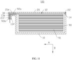
FIG. 1 is a first schematic structural diagram of a packaging housing according to an embodiment of this application. -
FIG. 2 is a first schematic structural sectional view of a packaging housing according to an embodiment of this application. -
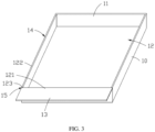
FIG. 3 is a first schematic structural diagram of a housing body in a packaging housing according to an embodiment of this application. -
FIG. 4 is a first schematic structural diagram of a cover in a packaging housing according to an embodiment of this application. -
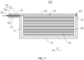
FIG. 5 is a second schematic structural sectional view of a packaging housing according to an embodiment of this application. -
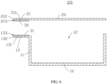
FIG. 6 is a schematic structural sectional view of a housing body and a cover in a packaging housing according to an embodiment of this application. -
FIG. 7 is a second schematic structural diagram of a packaging housing according to an embodiment of this application. -
FIG. 8 is a third schematic structural diagram of a packaging housing according to an embodiment of this application. -
FIG. 9 is a second schematic structural diagram of a housing body in a packaging housing according to an embodiment of this application. -
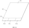
FIG. 10 is a second schematic structural diagram of a cover in a packaging housing according to an embodiment of this application. -
FIG. 11 is a fourth schematic structural diagram of a packaging housing according to an embodiment of this application. - The following describes the technical solutions in the embodiments of this application with reference to the accompanying drawings in the embodiments of this application. Apparently, the described embodiments are only some rather than all of the embodiments of this application.
- It should be noted that when a component is deemed as being "connected to" another component, it may be directly connected to the another component, or there may be a component disposed in between. When a component is deemed as being "disposed" on another component, it may be directly disposed on the another component, or there may be a component disposed in between.
- Unless otherwise defined, all technical and scientific terms used herein shall have the same meanings as commonly understood by those skilled in the art to which this application belongs. The terms used herein in the specification of this application are only used to describe specific embodiments, and are not intended to limit this application.
- It can be understood that when two components are disposed parallel/perpendicular to each other, an angular tolerance of 0-±10% is allowed between the two components. To be specific, an angular tolerance of ±18° exists when the two components are parallel to each other, and an angular tolerance of ±9° exists when the two components are perpendicular to each other. A value greater than, equal to or less than an endpoint value should be understood that a tolerance of 0-±10% of the endpoint value is allowed.
- An embodiment of this application provides a packaging housing for packaging a cell. The cell includes an electrode assembly and a tab electrically connected to the electrode assembly, and the packaging housing includes a housing body, a cover, and a polymer layer. The housing body is provided with an accommodating portion, where the accommodating portion is configured to accommodate the electrode assembly, the tab extends from the accommodating portion to the outside of the housing body, and the housing body is further provided with a first sealing portion extending from an edge of an opening of the accommodating portion to the outside of the housing body along a first direction. The cover is provided with a second sealing portion extending along the first direction. The cover covers the opening of the accommodating portion, and the first sealing portion and the second sealing portion are disposed opposite each other. The polymer layer is disposed between the first sealing portion and the second sealing portion. The polymer layer is configured to seal a gap between the first sealing portion and the second sealing portion. When pressure of gas generated by the cell inside the packaging housing exceeds a threshold, the polymer layer is further configured to release the gas from the packaging housing.
- In the packaging housing provided in the embodiments of this application, a battery using such packaging housing, and an electric device, the first sealing portion and the second sealing portion are disposed opposite each other, and the polymer layer is disposed between the first sealing portion and the second sealing portion, improving sealing performance of the packaging housing. In addition, when pressure of gas generated by the cell inside the packaging housing exceeds the threshold, the polymer layer is further configured to release the gas from the packaging housing, implementing timely pressure relief of the packaging housing and improving use safety. Compared with the existing method of disposing a pressure relief valve on the packaging housing, the packaging housing in the embodiments of this application can reduce production costs while improving safety.
- The following describes in detail some embodiments with reference to the accompanying drawings. In absence of conflicts, the following embodiments and features in the embodiments may be combined.
- Referring to
FIG. 1 andFIG. 2 , an embodiment of this application provides apackaging housing 100 for packaging acell 90. Thecell 90 includes anelectrode assembly 91 and atab 92 electrically connected to theelectrode assembly 91. Theelectrode assembly 91 may be formed by stacking in sequence or winding a positive electrode plate, a separator, and a negative electrode plate. - The
packaging housing 100 includes ahousing body 10, acover 20, and apolymer layer 30. Thehousing body 10 is provided with anaccommodating portion 11, and theaccommodating portion 11 is configured to accommodate theelectrode assembly 91. In some embodiments, theaccommodating portion 11 is a recessed portion disposed on thehousing body 10, and theelectrode assembly 91 is put into thehousing body 10 through anopening 12 of the accommodating portion 11 (that is, an opening of the recessed portion). Thetab 92 extends from theaccommodating portion 11 to the outside of thehousing body 10. - The
housing body 10 is further provided with afirst sealing portion 13 extending from an edge of theopening 12 of theaccommodating portion 11 to the outside of thehousing body 10 along a first direction A. Thecover 20 is provided with asecond sealing portion 21 extending along the first direction A. Thecover 20 covers theopening 12 of theaccommodating portion 11 to protect theelectrode assembly 91 in theaccommodating portion 11. Thefirst sealing portion 13 and thesecond sealing portion 21 are disposed opposite each other. - The
polymer layer 30 is disposed between thefirst sealing portion 13 and thesecond sealing portion 21. Thepolymer layer 30 is configured to seal a gap between thefirst sealing portion 13 and thesecond sealing portion 21. When pressure of gas generated by thecell 90 inside thepackaging housing 100 exceeds a threshold, thepolymer layer 30 is further configured to release the gas from thepackaging housing 100. - In some embodiments, the threshold is a pressure value of the gas generated inside the
packaging housing 100 when thermal runaway occurs on thecell 90. A melting point of thepolymer layer 30 is not higher than a thermal runaway temperature of thecell 90. When the thermal runaway of thecell 90 increases air pressure inside thepackaging housing 100, thepolymer layer 30 is melted by heat such that thefirst sealing portion 13 and thesecond sealing portion 21 are no longer sealed, implementing timely pressure relief of thepackaging housing 100 and improving use safety. - In some embodiments, a melting point of the
polymer layer 30 is 130°C to 150°C, and may specifically be one of 130°C, 135°C, 140°C, 145°C, 150°C, and the like. - In the foregoing
packaging housing 100, thefirst sealing portion 13 and thesecond sealing portion 21 are disposed opposite each other, and thepolymer layer 30 is disposed between thefirst sealing portion 13 and thesecond sealing portion 21, improving sealing performance of thepackaging housing 100. In addition, when pressure of gas generated by thecell 90 inside thepackaging housing 100 exceeds the threshold, thepolymer layer 30 is further configured to release the gas from thepackaging housing 100, implementing timely pressure relief of thepackaging housing 100 and improving use safety. Compared with the existing method of disposing a pressure relief valve on the packaging housing, thepackaging housing 100 in the embodiment of this application can reduce production costs while improving safety. - Still referring to
FIG. 2 , in some embodiments, thetab 92 is led out from between thefirst sealing portion 13 and thesecond sealing portion 21, and protrudes from thepolymer layer 30 to the outside of thehousing body 10, so as to improve sealing performance between thetab 92 and thepackaging housing 100. In some embodiments, thetab 92 protrudes from thepolymer layer 30 along the first direction A. - In some embodiments, the
polymer layer 30 has insulation properties to keep thetab 92 insulated from thehousing body 10 and thecover 20, which reduces the risk of thetab 92 being electrically connected to thehousing body 10 and thecover 20 so that thepackaging housing 100 is not charged. In this way, production costs for insulating the packaging housing are reduced, and production efficiency can be improved. - Still referring to
FIG. 2 , in some embodiments, thepolymer layer 30 includes afirst melting layer 31 and asecond melting layer 32. Thefirst melting layer 31 is disposed on a surface of thefirst sealing portion 13 facing toward thesecond sealing portion 21. Thesecond melting layer 32 is disposed on a surface of thesecond sealing portion 21 facing toward thefirst sealing portion 13. Thefirst melting layer 31 and thesecond melting layer 32 are configured to be melted by heat to form thepolymer layer 30, so as to seal a gap between thetab 92, thefirst sealing portion 13, and thesecond sealing portion 21. In some embodiments, thefirst melting layer 31 and thesecond melting layer 32 are melted by heat by hot pressing thefirst sealing portion 13 and thesecond sealing portion 21. - Referring to
FIG. 3 andFIG. 4 , in some embodiments, the edge of theopening 12 of theaccommodating portion 11 includes afirst edge 121 and asecond edge 122 that are connected end to end. Thefirst sealing portion 13 extends from thefirst edge 121 along the first direction A. Thehousing body 10 is further provided with a first connectingzone 14, and the first connectingzone 14 is provided on thesecond edge 122. A surface of thecover 20 facing toward theaccommodating portion 11 is provided with a second connectingzone 22 overlapping with the first connectingzone 14. - The first connecting
zone 14 and the second connectingzone 22 are welded to form a welded connecting layer to improve stability of the connection and sealing between thecover 20 and thehousing body 10. In addition, compared with the manner of folded edge, providing the first connectingzone 14 on thesecond edge 122 to fully use a surface on the edge of theopening 12 facing toward thecover 20 can reduce the space occupied by thepackaging housing 100 and increase the energy density of the battery. - In some embodiments, the
opening 12 has rectangular edges, with thefirst edge 121 being one side of the rectangle and the second edge being the other three sides of the rectangle. - It can be understood that in other embodiments, the
second edge 122 of theopening 12 of theaccommodating portion 11 bends outward to form a bending portion (not shown), and the first connectingzone 14 is provided on a surface of the bending portion facing toward thecover 20. Through the bending portion, the contact area between thehousing body 10 and thecover 20 is increased, and therefore the contact area between the first connectingzone 14 and the second connectingzone 22 can be increased, further improving the stability of the connection and sealing between thecover 20 and thehousing body 10. - In some examples, the
housing body 10 is further provided with afirst dispensing zone 15. Thefirst dispensing zone 15 is provided in anintersection area 123 between thefirst edge 121 and thesecond edge 122. A surface of thecover 20 facing toward theaccommodating portion 11 is provided with asecond dispensing zone 23 overlapping with thefirst dispensing zone 15. - The
first dispensing zone 15 and thesecond dispensing zone 23 form a dispensing connecting layer through dispensing to improve the stability of the connection and sealing between thecover 20 and thehousing body 10 in thecorresponding intersection area 123, thereby improving the stability of the connection and sealing at the intersection of the welded connecting layer and thepolymer layer 30. - Referring to
FIG. 5 , in some embodiments, thepackaging housing 100 further includes atab adhesive layer 50. Thetab adhesive layer 50 is disposed between the polymer layers 30, and thetab 92 protrudes from thetab adhesive layer 50 to the outside of thehousing body 10. Thetab adhesive layer 50 is configured to improve sealing performance between thetab 92 and thepolymer layer 30. - Specifically, in some embodiments, the
tab adhesive layer 50 is disposed between thefirst melting layer 31 and thesecond melting layer 32, and thetab 92 protrudes from thetab adhesive layer 50. Thefirst melting layer 31, thesecond melting layer 32, and thetab adhesive layer 50 are configured to be melted by heat to seal the gap between thetab 92 and thefirst sealing portion 13 and thesecond sealing portion 21. Thefirst melting layer 31, thesecond melting layer 32, and thetab adhesive layer 50 are melted synchronously, improving the sealing performance between thetab 92 and thepolymer layer 30 and further improving sealing performance of thepackaging housing 100. - In some embodiments, the
tab adhesive layer 50 has insulation properties to keep thetab 92 insulated from thehousing body 10 and thecover 20, which further reduces the risk of thetab 92 being electrically connected to thehousing body 10 and thecover 20 so that thepackaging housing 100 is not charged. - Still referring to
FIG. 6 , in some embodiments, thefirst sealing portion 13 includes afirst surface 131 and asecond surface 132. Thefirst surface 131 faces toward thesecond sealing portion 21, and thesecond surface 132 connects to a side of thefirst surface 131 far away from theaccommodating portion 11. Thefirst surface 131 and thesecond surface 132 sink to form afirst step face 133. Thefirst step face 133 is sealedly connected to thepolymer layer 30. When pressure of gas generated by thecell 90 inside thepackaging housing 100 exceeds the threshold, thepolymer layer 30 is burst open through an opening of thefirst step face 133 on thesecond surface 132 to release the gas from thepackaging housing 100, improving use safety of the battery. - In some embodiments, the
first melting layer 31 is disposed on thefirst step face 133. Thefirst melting layer 31 is applied on thefirst step face 133 and is flush with thefirst surface 131 to prevent the thickness of thefirst melting layer 31 from affecting the welding flatness between the first connectingzone 14 and the second connectingzone 22, and the tab improves the stability of the connection and sealing between thecover 20 and thehousing body 10. - Still referring to
FIG. 6 , in some embodiments, thesecond sealing portion 21 includes athird surface 211 and afourth surface 212. Thethird surface 211 faces toward thefirst surface 131, and thefourth surface 212 connects to a side of thethird surface 211 corresponding to thesecond surface 132. Thethird surface 211 and thefourth surface 212 sink to form asecond step face 213. Thesecond step face 213 is sealedly connected to thepolymer layer 30. When pressure of gas generated by thecell 90 inside thepackaging housing 100 exceeds the threshold, thepolymer layer 30 is burst open through an opening of thesecond step face 213 on thefourth surface 212 to release the gas from thepackaging housing 100, improving use safety of the battery. - In some embodiments, the
second melting layer 32 is disposed on thesecond step face 213. Thesecond melting layer 32 is applied on thesecond step face 213 and is flush with thethird face 211 to prevent the thickness of thesecond melting layer 32 from affecting the welding flatness between the first connectingzone 14 and the second connectingzone 22, and the tab improves the stability of the connection and sealing between thecover 20 and thehousing body 10. - Referring to
FIG. 7 , in some embodiments, thefirst sealing portion 13 extends from thefirst edge 121 along the first direction A, and thetab 92 extends from thesecond edge 122 to the outside of thehousing body 10. In other words, thetab 92 protrudes from the welded connecting layer to the outside of thehousing body 10. The welded connecting layer is configured to improve sealing performance between thetab 92 and thepackaging housing 100. Thepolymer layer 30 is configured to seal a gap between thefirst sealing portion 13 and thesecond sealing portion 21. When pressure of gas generated by thecell 90 inside thepackaging housing 100 exceeds the threshold, thepolymer layer 30 is further configured to release the gas from thepackaging housing 100. - In some embodiments, the
tab 92 protrudes from the welded connecting layer along an opposite direction of the first direction A. - Referring to
FIG. 8 , in some embodiments, both thefirst sealing portion 13 and thesecond sealing portion 21 are separate structures. Thefirst sealing portion 13 includes a firstseparate portion 13a and a secondseparate portion 13b that are spaced apart along the first direction A. Thesecond sealing portion 21 includes a thirdseparate portion 21a and a fourthseparate portion 21b, and the thirdseparate portion 21a and the fourthseparate portion 21b are disposed opposite the firstseparate portion 13a and the secondseparate portion 13b respectively. - The
polymer layer 30 is provided between the firstseparate portion 13a and the thirdseparate portion 21a for onetab 92 to run through thepolymer layer 30. Thepolymer layer 30 is provided between the secondseparate portion 13b and the fourthseparate portion 21b for anothertab 92 to run through, so as to reduce the space occupied by thefirst sealing portion 13 and thesecond sealing portion 21 and increase energy density of the battery. - In some embodiments, the
first edge 121 exposed between the firstseparate portion 13a and the secondseparate portion 13b is sealedly connected to a corresponding area of thecover 20 by welding and/or dispensing. - Referring to
FIG. 9 andFIG. 10 , in some embodiments, the surface of thefirst sealing portion 13 facing toward thesecond sealing portion 21 is provided with afirst area 13c and asecond area 13d. The surface of thesecond sealing portion 21 facing toward thefirst sealing portion 13 is provided with athird area 21c and afourth area 21d, and thethird area 21c and thefourth area 21d are disposed opposite thefirst area 13c and thesecond area 13d respectively. Thepolymer layer 30 is provided between thefirst sealing portion 13 and thethird area 21c for onetab 92 to run through. Thesecond area 13d and thefourth area 21d are sealedly connected by welding and/or dispensing. - Referring to
FIG. 11 , in some embodiments, thefirst sealing portion 13 includes afirst portion 13e and asecond portion 13f, thefirst portion 13e extends along the first direction A, and thesecond portion 13f extends along a second direction B, where the second direction B is a thickness direction of thecell 90, and the second direction B is perpendicular to the first direction A. Thesecond sealing portion 21 includes athird portion 21e and afourth portion 21f, and thethird portion 21e and thefourth portion 21f are disposed opposite thefirst portion 13e and thesecond portion 13f respectively. Thepolymer layer 30 is disposed between thefirst sealing portion 13 and thesecond sealing portion 21. - The
tab 92 includes afifth portion 92a and asixth portion 92b, thefifth portion 92a extends along the first direction A, and thesixth portion 92b extends along the second direction B. Thefifth portion 92a runs through thepolymer layer 30 between thefirst portion 13e and thethird portion 21e, and thesixth portion 92b runs through thepolymer layer 30 between thesecond portion 13f and thefourth portion 21f. - In some embodiments, an extension length of each of the
sixth portion 92b, thesecond portion 13f, and thefourth portion 21f along the second direction B is less than or equal to a thickness in the second direction B when thecover 20 covers thehousing body 10. - The
first sealing portion 13, thesecond sealing portion 21, and thetab 92 are bent to reduce the space occupied by thefirst sealing portion 13, thesecond bending portion 21, and thetab 92 in the first direction A, thereby increasing the energy density of the battery. - An embodiment of this application further provides a battery (not shown), including a
cell 90 and apackaging housing 100. Thepackaging housing 100 is configured to package thecell 90. Thepackaging housing 100 may be the packaging housing according to any one of the foregoing embodiments. - In some embodiments, the battery further includes a circuit protection board (not shown). The circuit protection board is configured to monitor voltage, current, insulation status, state of charge, and the like of the
battery cell 90 to provide safe management during charging and discharging of the battery, alarm and emergency protection for possible faults, and safety and optimization control for operation of the battery. - An embodiment of this application further provides an electric device (not shown), including the battery according to any one of the foregoing embodiments.
- In the foregoing battery and electric device, the
first sealing portion 13 and thesecond sealing portion 21 are disposed opposite each other, and thepolymer layer 30 is disposed between thefirst sealing portion 13 and thesecond sealing portion 21, improving sealing performance of thepackaging housing 100. In addition, when pressure of gas generated by thecell 90 inside thepackaging housing 100 exceeds the threshold, thepolymer layer 30 is further configured to release the gas from thepackaging housing 100, implementing timely pressure relief of thepackaging housing 100 and improving use safety. Compared with the existing method of disposing a pressure relief valve on the packaging housing, thepackaging housing 100 in the embodiment of this application can reduce production costs while improving safety. - In addition, those of ordinary skill in the art should be aware of that the foregoing embodiments are only intended to describe this application, but not to limit this application. Appropriate modifications and variations made to the foregoing embodiments without departing from the essential spirit and scope of this application all fall within the scope of this application.
| |
100 |
| |
10 |
| Accommodating |
11 |
| |
12 |
| |
121 |
| |
122 |
| |
123 |
| |
13 |
| |
131 |
| |
132 |
| |
133 |
| First |
13a |
| Second |
13b |
| |
13c |
| |
13d |
| |
13e |
| |
13f |
| First connecting |
14 |
| |
15 |
| |
20 |
| |
21 |
| |
211 |
| |
212 |
| |
213 |
| Third |
21a |
| Fourth |
21b |
| |
21c |
| |
21d |
| |
21e |
| |
21f |
| Second connecting |
22 |
| |
23 |
| |
30 |
| |
31 |
| |
32 |
| Tab |
50 |
| |
90 |
| |
91 |
| |
92 |
| |
92a |
| |
92b |
| First direction | A |
| Second direction | B |
Claims (10)
- A packaging housing for packaging a cell, the cell comprising an electrode assembly and a tab electrically connected to the electrode assembly, characterized in that the packaging housing comprises:a housing body, provided with an accommodating portion, wherein the accommodating portion is configured to accommodate the electrode assembly, the tab extends from the accommodating portion to the outside of the housing body, and the housing body is further provided with a first sealing portion extending from an edge of an opening of the accommodating portion to the outside of the housing body along a first direction;a cover, provided with a second sealing portion extending along the first direction, wherein the cover covers the opening of the accommodating portion, and the first sealing portion and the second sealing portion are disposed opposite each other; anda polymer layer, disposed between the first sealing portion and the second sealing portion,wherein the polymer layer is configured to seal a gap between the first sealing portion and the second sealing portion, and when pressure of gas generated by the cell inside the packaging housing exceeds a threshold, the polymer layer is further configured to release the gas from the packaging housing.
- The packaging housing according to claim 1, characterized in that the tab protrudes from the polymer layer to the outside of the housing body.
- The packaging housing according to claim 1, characterized in that the edge of the opening of the accommodating portion comprises a first edge and a second edge that are connected end to end, the first sealing portion extends from the first edge along the first direction, the housing body is further provided with a first connecting zone, the first connecting zone is provided on the second edge, a surface of the cover facing toward the accommodating portion is provided with a second connecting zone overlapping with the first connecting zone, and the first connecting zone and the second connecting zone are welded to form a welded connecting layer.
- The packaging housing according to claim 3, characterized in that the second edge of the opening of the accommodating portion bends outward to form a bending portion, and the first connecting zone is provided on a surface of the bending portion facing toward the cover.
- The packaging housing according to claim 3, characterized in that the housing body is further provided with a first dispensing zone, the first dispensing zone is provided in an intersection area between the first edge and the second edge, a surface of the cover facing toward the accommodating portion is provided with a second dispensing zone overlapping with the first dispensing zone, and the first dispensing zone and the second dispensing zone form a dispensing connecting layer through dispensing.
- The packaging housing according to claim 1, characterized in that the packaging housing further comprises a tab adhesive layer, wherein the tab adhesive layer is disposed between the polymer layers, and the tab protrudes from the tab adhesive layer to the outside of the housing body.
- The packaging housing according to claim 1, characterized in that the first sealing portion comprises a first surface and a second surface, wherein the first surface faces toward the second sealing portion, the second surface connects to a side of the first surface far away from the accommodating portion, the first surface and the second surface sink to form a first step face, and the first step face is sealedly connected to the polymer layer.
- The packaging housing according to claim 7, characterized in that the second sealing portion comprises a third surface and a fourth surface, wherein the third surface faces toward the first surface, the fourth surface connects to a side of the third surface corresponding to the second surface, the third surface and the fourth surface sink to form a second step face, and the second step face is sealedly connected to the polymer layer.
- A battery, comprising a cell, characterized in that the battery further comprises the packaging housing according to any one of claims 1 to 8.
- An electric device, characterized by comprising the battery according to claim 9.
Applications Claiming Priority (2)
| Application Number | Priority Date | Filing Date | Title |
|---|---|---|---|
| CN202121929405.5U CN215896547U (en) | 2021-08-17 | 2021-08-17 | Packaging shell, battery and electric equipment |
| PCT/CN2022/112999 WO2023020533A1 (en) | 2021-08-17 | 2022-08-17 | Encapsulation casing, battery, and electrical device |
Publications (2)
| Publication Number | Publication Date |
|---|---|
| EP4207447A1 true EP4207447A1 (en) | 2023-07-05 |
| EP4207447A4 EP4207447A4 (en) | 2025-01-22 |
Family
ID=80563605
Family Applications (1)
| Application Number | Title | Priority Date | Filing Date |
|---|---|---|---|
| EP22857844.9A Pending EP4207447A4 (en) | 2021-08-17 | 2022-08-17 | ENCAPSULATION PACKAGING, BATTERY AND ELECTRICAL DEVICE |
Country Status (5)
| Country | Link |
|---|---|
| US (1) | US20230238668A1 (en) |
| EP (1) | EP4207447A4 (en) |
| JP (1) | JP7607056B2 (en) |
| CN (2) | CN215896547U (en) |
| WO (1) | WO2023020533A1 (en) |
Families Citing this family (2)
| Publication number | Priority date | Publication date | Assignee | Title |
|---|---|---|---|---|
| CN215896547U (en) * | 2021-08-17 | 2022-02-22 | 宁德新能源科技有限公司 | Packaging shell, battery and electric equipment |
| CN118523046B (en) * | 2024-07-23 | 2025-03-07 | 中航锂电(洛阳)有限公司 | Battery cell, soft package battery, electric equipment and preparation method of soft package battery |
Citations (2)
| Publication number | Priority date | Publication date | Assignee | Title |
|---|---|---|---|---|
| JP2003346768A (en) | 2002-05-29 | 2003-12-05 | Japan Storage Battery Co Ltd | Non-aqueous electrolyte secondary battery |
| JP2017062872A (en) | 2015-09-23 | 2017-03-30 | 株式会社デンソー | Nonaqueous electrolyte secondary battery |
Family Cites Families (12)
| Publication number | Priority date | Publication date | Assignee | Title |
|---|---|---|---|---|
| JP4622019B2 (en) | 1999-01-20 | 2011-02-02 | パナソニック株式会社 | Flat battery |
| JP4762411B2 (en) * | 2000-06-26 | 2011-08-31 | パナソニック株式会社 | Non-aqueous electrolyte for secondary battery and non-aqueous electrolyte secondary battery using the same |
| US20030232236A1 (en) | 2002-06-14 | 2003-12-18 | Mitchell Porter H. | Battery package vent |
| JP4232038B2 (en) * | 2004-08-11 | 2009-03-04 | 日本電気株式会社 | Film-clad electrical device and method for manufacturing the same |
| KR100601547B1 (en) | 2004-10-01 | 2006-07-19 | 삼성에스디아이 주식회사 | Pouch Type Secondary Battery |
| KR100684724B1 (en) * | 2005-04-26 | 2007-02-20 | 삼성에스디아이 주식회사 | Secondary Battery and Safety Device Used in It |
| KR101082196B1 (en) | 2009-12-23 | 2011-11-09 | 삼성에스디아이 주식회사 | Secondary Battery and Manufacturing Method thereof |
| KR101914564B1 (en) * | 2012-03-02 | 2018-11-02 | 삼성에스디아이 주식회사 | Secondary battery with insulation member |
| US10734626B2 (en) * | 2015-08-25 | 2020-08-04 | Envision Aesc Energy Devices Ltd. | Electrochemical device |
| KR102818645B1 (en) | 2019-08-19 | 2025-06-10 | 삼성에스디아이 주식회사 | Rechargeable battery |
| KR20220162119A (en) | 2020-04-02 | 2022-12-07 | 다이니폰 인사츠 가부시키가이샤 | Adhesive film for metal terminals, manufacturing method of adhesive film for metal terminals, metal terminal with adhesive film for metal terminals, electrical storage device, and manufacturing method of electrical storage device |
| CN215896547U (en) * | 2021-08-17 | 2022-02-22 | 宁德新能源科技有限公司 | Packaging shell, battery and electric equipment |
-
2021
- 2021-08-17 CN CN202121929405.5U patent/CN215896547U/en active Active
-
2022
- 2022-08-17 EP EP22857844.9A patent/EP4207447A4/en active Pending
- 2022-08-17 CN CN202280013783.XA patent/CN117223156A/en active Pending
- 2022-08-17 JP JP2022569630A patent/JP7607056B2/en active Active
- 2022-08-17 WO PCT/CN2022/112999 patent/WO2023020533A1/en not_active Ceased
-
2023
- 2023-03-30 US US18/128,593 patent/US20230238668A1/en active Pending
Patent Citations (2)
| Publication number | Priority date | Publication date | Assignee | Title |
|---|---|---|---|---|
| JP2003346768A (en) | 2002-05-29 | 2003-12-05 | Japan Storage Battery Co Ltd | Non-aqueous electrolyte secondary battery |
| JP2017062872A (en) | 2015-09-23 | 2017-03-30 | 株式会社デンソー | Nonaqueous electrolyte secondary battery |
Non-Patent Citations (1)
| Title |
|---|
| See also references of WO2023020533A1 |
Also Published As
| Publication number | Publication date |
|---|---|
| WO2023020533A1 (en) | 2023-02-23 |
| JP7607056B2 (en) | 2024-12-26 |
| CN117223156A (en) | 2023-12-12 |
| CN215896547U (en) | 2022-02-22 |
| JP2023541747A (en) | 2023-10-04 |
| EP4207447A4 (en) | 2025-01-22 |
| US20230238668A1 (en) | 2023-07-27 |
Similar Documents
| Publication | Publication Date | Title |
|---|---|---|
| US11909065B2 (en) | Cover plate assembly, battery cell, battery module, battery pack, and apparatus | |
| US11688907B2 (en) | End cap assembly, battery cell and manufacturing method thereof, battery, and electric apparatus | |
| EP2602840B1 (en) | Secondary battery pouch having improved stability, pouch-type secondary battery using same, and medium- or large-sized battery pack | |
| CN101312253B (en) | Bag type secondary battery | |
| US12002994B2 (en) | Battery module, battery pack, and battery-powered apparatus | |
| US11271274B2 (en) | Secondary battery | |
| US12300828B2 (en) | Battery module and battery pack | |
| CN112510242B (en) | Secondary battery and terminal device | |
| EP4207447A1 (en) | Encapsulation casing, battery, and electrical device | |
| CN217788566U (en) | Battery cell, battery and power consumption device | |
| US11355825B2 (en) | Battery pack and manufacturing method therefor | |
| WO2021217649A1 (en) | End cap assembly, secondary battery, battery pack, and powered device | |
| WO2021195852A1 (en) | Battery assembly, and battery and electronic device using same | |
| KR20180091324A (en) | Battery cell and Secondary battery assembly comprising the same | |
| EP4075584A1 (en) | Battery cell, battery, electrical device, and method for manufacturing battery cell | |
| KR100516772B1 (en) | Secondary Battery having a Tap in Short Part of Can | |
| CN114171841B (en) | Cover plate assembly, battery and electricity utilization device | |
| JP2015026611A (en) | Electrode assembly and secondary battery including the same | |
| CN214754076U (en) | Battery cell structure and lithium ion battery | |
| CN113597701B (en) | Electrochemical device and electronic device | |
| CN219498130U (en) | Battery pack | |
| KR100686839B1 (en) | Secondary battery | |
| WO2021189380A1 (en) | Electrochemical device and electronic device | |
| WO2023130279A1 (en) | Battery cell and manufacturing device and method therefor, battery, and electronic apparatus | |
| CN114552092A (en) | Protection piece, battery component assembly, battery pack and power supply system |
Legal Events
| Date | Code | Title | Description |
|---|---|---|---|
| STAA | Information on the status of an ep patent application or granted ep patent |
Free format text: STATUS: THE INTERNATIONAL PUBLICATION HAS BEEN MADE |
|
| PUAI | Public reference made under article 153(3) epc to a published international application that has entered the european phase |
Free format text: ORIGINAL CODE: 0009012 |
|
| STAA | Information on the status of an ep patent application or granted ep patent |
Free format text: STATUS: REQUEST FOR EXAMINATION WAS MADE |
|
| 17P | Request for examination filed |
Effective date: 20230330 |
|
| AK | Designated contracting states |
Kind code of ref document: A1 Designated state(s): AL AT BE BG CH CY CZ DE DK EE ES FI FR GB GR HR HU IE IS IT LI LT LU LV MC MK MT NL NO PL PT RO RS SE SI SK SM TR |
|
| DAV | Request for validation of the european patent (deleted) | ||
| DAX | Request for extension of the european patent (deleted) | ||
| A4 | Supplementary search report drawn up and despatched |
Effective date: 20241219 |
|
| RIC1 | Information provided on ipc code assigned before grant |
Ipc: H01M 50/55 20210101ALI20241213BHEP Ipc: H01M 50/30 20210101ALI20241213BHEP Ipc: H01M 50/198 20210101ALI20241213BHEP Ipc: H01M 50/193 20210101ALI20241213BHEP Ipc: H01M 50/124 20210101ALI20241213BHEP Ipc: H01M 50/103 20210101ALI20241213BHEP Ipc: H01M 50/121 20210101ALI20241213BHEP Ipc: H01M 50/186 20210101AFI20241213BHEP |
|
| TPAC | Observations filed by third parties |
Free format text: ORIGINAL CODE: EPIDOSNTIPA |