EP4207440A1 - Secondary battery and a method of manufacturing a secondary battery - Google Patents
Secondary battery and a method of manufacturing a secondary battery Download PDFInfo
- Publication number
- EP4207440A1 EP4207440A1 EP22203572.7A EP22203572A EP4207440A1 EP 4207440 A1 EP4207440 A1 EP 4207440A1 EP 22203572 A EP22203572 A EP 22203572A EP 4207440 A1 EP4207440 A1 EP 4207440A1
- Authority
- EP
- European Patent Office
- Prior art keywords
- secondary battery
- plate
- short side
- electrode plate
- long
- Prior art date
- Legal status (The legal status is an assumption and is not a legal conclusion. Google has not performed a legal analysis and makes no representation as to the accuracy of the status listed.)
- Granted
Links
Images



Classifications
-
- H—ELECTRICITY
- H01—ELECTRIC ELEMENTS
- H01M—PROCESSES OR MEANS, e.g. BATTERIES, FOR THE DIRECT CONVERSION OF CHEMICAL ENERGY INTO ELECTRICAL ENERGY
- H01M50/00—Constructional details or processes of manufacture of the non-active parts of electrochemical cells other than fuel cells, e.g. hybrid cells
- H01M50/10—Primary casings; Jackets or wrappings
- H01M50/102—Primary casings; Jackets or wrappings characterised by their shape or physical structure
- H01M50/103—Primary casings; Jackets or wrappings characterised by their shape or physical structure prismatic or rectangular
-
- H—ELECTRICITY
- H01—ELECTRIC ELEMENTS
- H01M—PROCESSES OR MEANS, e.g. BATTERIES, FOR THE DIRECT CONVERSION OF CHEMICAL ENERGY INTO ELECTRICAL ENERGY
- H01M50/00—Constructional details or processes of manufacture of the non-active parts of electrochemical cells other than fuel cells, e.g. hybrid cells
- H01M50/10—Primary casings; Jackets or wrappings
- H01M50/131—Primary casings; Jackets or wrappings characterised by physical properties, e.g. gas permeability, size or heat resistance
- H01M50/133—Thickness
-
- H—ELECTRICITY
- H01—ELECTRIC ELEMENTS
- H01M—PROCESSES OR MEANS, e.g. BATTERIES, FOR THE DIRECT CONVERSION OF CHEMICAL ENERGY INTO ELECTRICAL ENERGY
- H01M50/00—Constructional details or processes of manufacture of the non-active parts of electrochemical cells other than fuel cells, e.g. hybrid cells
- H01M50/10—Primary casings; Jackets or wrappings
- H01M50/147—Lids or covers
- H01M50/166—Lids or covers characterised by the methods of assembling casings with lids
- H01M50/169—Lids or covers characterised by the methods of assembling casings with lids by welding, brazing or soldering
-
- H—ELECTRICITY
- H01—ELECTRIC ELEMENTS
- H01M—PROCESSES OR MEANS, e.g. BATTERIES, FOR THE DIRECT CONVERSION OF CHEMICAL ENERGY INTO ELECTRICAL ENERGY
- H01M50/00—Constructional details or processes of manufacture of the non-active parts of electrochemical cells other than fuel cells, e.g. hybrid cells
- H01M50/10—Primary casings; Jackets or wrappings
- H01M50/172—Arrangements of electric connectors penetrating the casing
- H01M50/174—Arrangements of electric connectors penetrating the casing adapted for the shape of the cells
- H01M50/176—Arrangements of electric connectors penetrating the casing adapted for the shape of the cells for prismatic or rectangular cells
-
- H—ELECTRICITY
- H01—ELECTRIC ELEMENTS
- H01M—PROCESSES OR MEANS, e.g. BATTERIES, FOR THE DIRECT CONVERSION OF CHEMICAL ENERGY INTO ELECTRICAL ENERGY
- H01M50/00—Constructional details or processes of manufacture of the non-active parts of electrochemical cells other than fuel cells, e.g. hybrid cells
- H01M50/10—Primary casings; Jackets or wrappings
- H01M50/183—Sealing members
-
- H—ELECTRICITY
- H01—ELECTRIC ELEMENTS
- H01M—PROCESSES OR MEANS, e.g. BATTERIES, FOR THE DIRECT CONVERSION OF CHEMICAL ENERGY INTO ELECTRICAL ENERGY
- H01M50/00—Constructional details or processes of manufacture of the non-active parts of electrochemical cells other than fuel cells, e.g. hybrid cells
- H01M50/10—Primary casings; Jackets or wrappings
- H01M50/183—Sealing members
- H01M50/186—Sealing members characterised by the disposition of the sealing members
- H01M50/188—Sealing members characterised by the disposition of the sealing members the sealing members being arranged between the lid and terminal
-
- H—ELECTRICITY
- H01—ELECTRIC ELEMENTS
- H01M—PROCESSES OR MEANS, e.g. BATTERIES, FOR THE DIRECT CONVERSION OF CHEMICAL ENERGY INTO ELECTRICAL ENERGY
- H01M50/00—Constructional details or processes of manufacture of the non-active parts of electrochemical cells other than fuel cells, e.g. hybrid cells
- H01M50/30—Arrangements for facilitating escape of gases
- H01M50/342—Non-re-sealable arrangements
- H01M50/3425—Non-re-sealable arrangements in the form of rupturable membranes or weakened parts, e.g. pierced with the aid of a sharp member
-
- H—ELECTRICITY
- H01—ELECTRIC ELEMENTS
- H01M—PROCESSES OR MEANS, e.g. BATTERIES, FOR THE DIRECT CONVERSION OF CHEMICAL ENERGY INTO ELECTRICAL ENERGY
- H01M50/00—Constructional details or processes of manufacture of the non-active parts of electrochemical cells other than fuel cells, e.g. hybrid cells
- H01M50/50—Current conducting connections for cells or batteries
- H01M50/543—Terminals
- H01M50/547—Terminals characterised by the disposition of the terminals on the cells
- H01M50/548—Terminals characterised by the disposition of the terminals on the cells on opposite sides of the cell
-
- H—ELECTRICITY
- H01—ELECTRIC ELEMENTS
- H01M—PROCESSES OR MEANS, e.g. BATTERIES, FOR THE DIRECT CONVERSION OF CHEMICAL ENERGY INTO ELECTRICAL ENERGY
- H01M2200/00—Safety devices for primary or secondary batteries
- H01M2200/20—Pressure-sensitive devices
-
- Y—GENERAL TAGGING OF NEW TECHNOLOGICAL DEVELOPMENTS; GENERAL TAGGING OF CROSS-SECTIONAL TECHNOLOGIES SPANNING OVER SEVERAL SECTIONS OF THE IPC; TECHNICAL SUBJECTS COVERED BY FORMER USPC CROSS-REFERENCE ART COLLECTIONS [XRACs] AND DIGESTS
- Y02—TECHNOLOGIES OR APPLICATIONS FOR MITIGATION OR ADAPTATION AGAINST CLIMATE CHANGE
- Y02E—REDUCTION OF GREENHOUSE GAS [GHG] EMISSIONS, RELATED TO ENERGY GENERATION, TRANSMISSION OR DISTRIBUTION
- Y02E60/00—Enabling technologies; Technologies with a potential or indirect contribution to GHG emissions mitigation
- Y02E60/10—Energy storage using batteries
-
- Y—GENERAL TAGGING OF NEW TECHNOLOGICAL DEVELOPMENTS; GENERAL TAGGING OF CROSS-SECTIONAL TECHNOLOGIES SPANNING OVER SEVERAL SECTIONS OF THE IPC; TECHNICAL SUBJECTS COVERED BY FORMER USPC CROSS-REFERENCE ART COLLECTIONS [XRACs] AND DIGESTS
- Y02—TECHNOLOGIES OR APPLICATIONS FOR MITIGATION OR ADAPTATION AGAINST CLIMATE CHANGE
- Y02P—CLIMATE CHANGE MITIGATION TECHNOLOGIES IN THE PRODUCTION OR PROCESSING OF GOODS
- Y02P70/00—Climate change mitigation technologies in the production process for final industrial or consumer products
- Y02P70/50—Manufacturing or production processes characterised by the final manufactured product
Definitions
- aspects of some embodiments of the present disclosure relate to a secondary battery and a method of manufacturing a secondary battery.
- a secondary battery is battery that can generally be repeatedly charged and discharged.
- a low-capacity secondary battery may include one single cell packaged in the form of a pack, and may be used for various portable small-sized electronic devices, such as cellular phones or camcorders, and a high-capacity secondary battery in which several tens of cells are connected in a battery pack is widely used as a power source for motor drives, such as those in hybrid vehicles or electric vehicles.
- Such secondary batteries may be classified into a cylindrical battery, a prismatic battery, a pouch-type (or polymer-type) battery, and the like, according to their external appearance.
- the prismatic battery may be formed by incorporating into a can an electrode assembly formed with a separator interposed between a positive electrode plate and a negative electrode plate, an electrolyte, and the like, and installing a cap plate in the can.
- aspects of some embodiments of the present disclosure include a secondary battery which can be relatively easily manufactured and a method of manufacturing thereof.
- aspects of some embodiments of the present disclosure include a secondary battery having excellent stability.
- a secondary battery includes an electrode assembly comprising a first electrode plate, a second electrode plate, and a separator interposed between the first electrode plate and the second electrode plate, a can for accommodating the electrode assembly, the can formed in a pipe shape and having a thickness varying along the circumferential direction, a first side plate for sealing an open end of the can, a second side plate for sealing the other open end of the can, a first side terminal electrically connected to the first electrode plate and exposed to the outside through the first side plate, and a second side terminal electrically connected to the second electrode plate and exposed to the outside through the second side plate.
- the can may be formed in a rectangular pipe shape, and may have a first short side, a second short side, a first long side, and a second long side.
- the thickness of each of the first short side and the second short side may be greater than the thickness of each of the first long side and the second long side.
- a safety vent may be positioned on the second short side, and the thickness of the second short side may be greater than the thickness of each of the first short side, the first long side, and the second long side.
- a hole may be formed in the second short side, and the safety vent may be located on the hole to be fixed by lap welding.
- a method is provided of manufacturing a secondary battery including an electrode assembly comprising a first electrode plate, a second electrode plate, and a separator interposed between the first electrode plate and the second electrode plate, and a can for accommodating the electrode assembly.
- the method includes: molding one long rectangular pipe by an extrusion process, cutting the long rectangular pipe to a certain length to form a first short side, a second short side, a first long side, and a second long side of the can, welding a first side plate to one end of the can, welding a second side plate to the other end of the can.
- the method may further include fixing a safety vent on a hole in the second short side (112) by lap welding.
- first, second, etc. may be used herein to describe various members, elements, regions, layers and/or sections, these members, elements, regions, layers and/or sections should not be limited by these terms. These terms are only used to distinguish one member, element, region, layer and/or section from another. Thus, for example, a first member, a first element, a first region, a first layer and/or a first section discussed below could be termed a second member, a second element, a second region, a second layer and/or a second section without departing from the teachings of the present invention.
- spatially relative terms such as “beneath,” “below,” “lower,” “above,” “upper,” and the like, may be used herein for ease of description to describe one element or feature's relationship to another element(s) or feature(s) as illustrated in the figures. It will be understood that the spatially relative terms are intended to encompass different orientations of the device in use or operation in addition to the orientation depicted in the figures. For example, if the element or feature in the figures is turned over, elements described as “below” or “beneath” other elements or features would then be oriented “on” or “above” the other elements or features. Thus, the term “below” can encompass both an orientation of above and below.
- FIG. 1 is a perspective view of a secondary battery 100 according to some embodiments of the present disclosure
- FIG. 2 is a front view of the secondary battery 100 according to some embodiments of the present disclosure
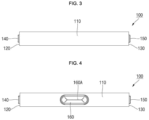
- FIG. 3 is a top view of the a secondary battery 100 according to some embodiments of the present disclosure
- FIG. 4 is a bottom view of the secondary battery 100 according to some embodiments of the present disclosure
- FIG. 5 is a left side view of the secondary battery 100 according to some embodiments of the present disclosure
- FIG. 6 is a right side view of the secondary battery 100 according to some embodiments of the present disclosure.
- the secondary battery 100 includes an electrode assembly, a can 110, a first side plate 120, a second side plate 130, a first side terminal 140, and a second side terminal 150.
- the electrode assembly according to some embodiments may be located inside the can 110.
- the electrode assembly includes a first electrode plate, a second electrode plate, and a separator.
- the first electrode plate may be any one of a negative electrode plate and a positive electrode plate.
- the first electrode plate when the first electrode plate is a negative electrode plate, the first electrode plate may include a negative electrode coated portion that is coated with a negative electrode active material and a negative electrode uncoated portion that is not coated with a negative electrode active material, on a negative electrode current collector plate made of a conductive metal thin plate, for example, copper or nickel foil or mesh.
- the negative electrode active material may include, for example, a carbon-based material, Si, Sn, tin oxide, a tin alloy composite, transition metal oxide, lithium metal nitrite, or metal oxide.
- the second electrode plate may be the other one of a negative electrode plate and a positive electrode plate.
- the second electrode plate when the second electrode plate is a positive electrode plate, the second electrode plate may include a positive electrode coated portion that is coated with a positive electrode active material and a positive electrode uncoated portion that is not coated with a positive electrode active material, on a positive electrode current collector plate made of a thin conductive metal plate, for example, aluminum foil or mesh.
- the positive electrode active material may include a chalcogenide compound, for example, a composite metal oxide, such as LiCoO 2 , LiMn 2 O 4 , LiNiO 2 , LiNiMnO 2 , or the like.
- the separator is interposed between the first electrode plate and the second electrode plate, and serves to prevent an electrical short between the first electrode plate and the second electrode plate.
- the separator may be made of, for example, polyethylene, polypropylene, a porous copolymer of polyethylene and polypropylene, or the like.
- the can 110 serves to accommodate the electrode assembly and an electrolyte.
- the can 110 is formed in a pipe shape (e.g., a tube or conduit shape).
- a pipe shape e.g., a tube or conduit shape
- the can 110 is shown by way of example as being formed in a rectangular pipe shape (e.g., a tube having a rectangular cross-section).
- two regions having relatively short sides are referred to as a first short side 111 and a second short side 112, respectively, and two regions having relatively long sides are referred to as a first long side 113 and a second long side 114, respectively.
- the thicknesses t1 and t2 of the first short side 111 and the second short side 112 are greater than the thicknesses t3 and t4 of the first long side 113 and the second long side 114. Accordingly, with respect to the first short side 111 and the second short side 112, the rigidity and cooling efficiency may be improved.
- the safety vent 160 may be positioned on the second short side 112.
- the safety vent 160 When gas is generated inside the can 110, the safety vent 160 is automatically ruptured by the pressure due to the generated gas to release the gas and pressure, thereby preventing the secondary battery 100 from exploding.
- the safety vent 160 may have a notch 160A formed to induce rupture.
- the safety vent 160 may have a hole formed through the second short side 112 and may be located on the hole to then be fixed by lap welding.
- the thickness t2 of the second short side 112 is preferably greater than the thickness t1 of the first short side 111. Accordingly, by reinforcing rigidity through a relatively large thickness, it is possible to prevent the second short side 112 from being unintentionally deformed during lap welding.
- the thickness t2 of the second short side 112 is largest, and the thickness t1 of the first short side 111 may be greater than the thicknesses t3 and t4 of the first and second long sides 114.
- the thickness of the can 110 along the circumference e.g., the edges in a cross section
- a circumferential direction may vary.
- FIG. 8 is a schematic diagram of a process of manufacturing a can of a secondary battery according to some embodiments of the present disclosure
- the can 110 may be formed by being molded into one long rectangular pipe by an extrusion process and then cut to a certain length.
- the thicknesses of the first short side 111, the second short side 112, the first long side 113, and the second long side 114 can be easily set.
- the first side plate 120 is formed in a square plate shape to correspond to the open end of the can 110. Accordingly, the first side plate 120 is welded to one end of the can 110 and serves to seal.
- the second side plate 130 is formed in a square plate shape to correspond to the other open end of the can 110. Accordingly, the second side plate 130 is welded to the other end of the can 110 and serves to seal.
- the first side terminal 140 is electrically connected to a negative electrode uncoated portion of the first electrode plate of the electrode assembly, passes through the first side plate 120 and is exposed to the outside. Accordingly, the first side terminal 140 serves as a negative electrode terminal. In this case, an insulating member is provided between the first side terminal 140 and the first side plate 120 to prevent an electrical short therebetween.
- the second side terminal 150 is electrically connected to a positive electrode uncoated portion of the second electrode plate of the electrode assembly, penetrates the second side plate 130 and is exposed to the outside. Accordingly, the second side terminal 150 serves as a positive electrode terminal. In this case, an insulating member is provided between the second side terminal 150 and the second side plate 130 to prevent an electrical short therebetween.
- the negative electrode terminal (first side terminal) and the positive electrode terminal (second side terminal) are provided on the left and right sides, the upper and lower portions thereof can be effectively cooled at the same time.
- a negative electrode terminal and a positive electrode terminal are provided on the upper portion thereof, there is a disadvantage in that the upper portion is difficult to cool.
- some embodiments of the present disclosure may include a secondary battery which can be relatively easily manufactured by manufacturing a can by forming a single long rectangular pipe through an extrusion process and cutting the same to a length (e.g., a set or predetermined length).
- the rigidity and cooling efficiency can be improved.
- the structural stability when the safety vent is installed can be reinforced.
Landscapes
- Chemical & Material Sciences (AREA)
- Chemical Kinetics & Catalysis (AREA)
- Electrochemistry (AREA)
- General Chemical & Material Sciences (AREA)
- Sealing Battery Cases Or Jackets (AREA)
- Secondary Cells (AREA)
Abstract
Description
- Aspects of some embodiments of the present disclosure relate to a secondary battery and a method of manufacturing a secondary battery.
- Unlike a primary battery that cannot be charged, a secondary battery is battery that can generally be repeatedly charged and discharged. A low-capacity secondary battery may include one single cell packaged in the form of a pack, and may be used for various portable small-sized electronic devices, such as cellular phones or camcorders, and a high-capacity secondary battery in which several tens of cells are connected in a battery pack is widely used as a power source for motor drives, such as those in hybrid vehicles or electric vehicles. Such secondary batteries may be classified into a cylindrical battery, a prismatic battery, a pouch-type (or polymer-type) battery, and the like, according to their external appearance. For example, the prismatic battery may be formed by incorporating into a can an electrode assembly formed with a separator interposed between a positive electrode plate and a negative electrode plate, an electrolyte, and the like, and installing a cap plate in the can.
- The above information disclosed in this Background section is only for enhancement of understanding of the background and therefore the information discussed in this Background section does not necessarily constitute prior art.
- Aspects of some embodiments of the present disclosure include a secondary battery which can be relatively easily manufactured and a method of manufacturing thereof.
- In addition, aspects of some embodiments of the present disclosure include a secondary battery having excellent stability.
- A secondary battery according to some embodiments of the present disclosure includes an electrode assembly comprising a first electrode plate, a second electrode plate, and a separator interposed between the first electrode plate and the second electrode plate, a can for accommodating the electrode assembly, the can formed in a pipe shape and having a thickness varying along the circumferential direction, a first side plate for sealing an open end of the can, a second side plate for sealing the other open end of the can, a first side terminal electrically connected to the first electrode plate and exposed to the outside through the first side plate, and a second side terminal electrically connected to the second electrode plate and exposed to the outside through the second side plate.
- According to some embodiments, the can may be formed in a rectangular pipe shape, and may have a first short side, a second short side, a first long side, and a second long side.
- According to some embodiments, the thickness of each of the first short side and the second short side may be greater than the thickness of each of the first long side and the second long side.
- According to some embodiments, a safety vent may be positioned on the second short side, and the thickness of the second short side may be greater than the thickness of each of the first short side, the first long side, and the second long side.
- According to some embodiments, a hole may be formed in the second short side, and the safety vent may be located on the hole to be fixed by lap welding.
- According to some embodiments of the present disclosure, a method is provided of manufacturing a secondary battery including an electrode assembly comprising a first electrode plate, a second electrode plate, and a separator interposed between the first electrode plate and the second electrode plate, and a can for accommodating the electrode assembly. The method includes: molding one long rectangular pipe by an extrusion process, cutting the long rectangular pipe to a certain length to form a first short side, a second short side, a first long side, and a second long side of the can, welding a first side plate to one end of the can, welding a second side plate to the other end of the can.
- According to some embodiments, the method may further include fixing a safety vent on a hole in the second short side (112) by lap welding.
-
-
FIG. 1 is a perspective view of a secondary battery according to some embodiments of the present disclosure. -
FIG. 2 is a front view of a secondary battery according to some embodiments of the present disclosure. -
FIG. 3 is a plan view of a secondary battery according to some embodiments of the present disclosure. -
FIG. 4 is a bottom view of a secondary battery according to some embodiments of the present disclosure. -
FIG. 5 is a left side view of a secondary battery according to some embodiments of the present disclosure. -
FIG. 6 is a right side view of a secondary battery according to some embodiments of the present disclosure. -
FIG. 7 is a cross-sectional view of a can of a secondary battery according to some embodiments of the present disclosure, taken along the line 7-7 inFIG. 1 . -
FIG. 8 is a schematic diagram of a process of manufacturing a can of a secondary battery according to some embodiments of the present disclosure. - Hereinafter, preferred embodiments of the present invention will be described in detail with reference to the accompanying drawings.
- Examples of the present invention are provided to more completely explain the present invention to those skilled in the art, and the following examples may be modified in various other forms. The present invention, however, may be embodied in many different forms and should not be construed as being limited to the example (or illustrated) embodiments set forth herein. Rather, these example embodiments are provided so that this disclosure will be thorough and complete and will convey the aspects and features of the present invention to those skilled in the art.
- In addition, in the accompanying drawings, sizes or thicknesses of various components are exaggerated for brevity and clarity. Like numbers refer to like elements throughout. As used herein, the term "and/or" includes any and all combinations of one or more of the associated listed items. In addition, it will be understood that when an element A is referred to as being "connected to" an element B, the element A can be directly connected to the element B or an intervening element C may be present therebetween such that the element A and the element B are indirectly connected to each other.
- The terminology used herein is for the purpose of describing particular embodiments only and is not intended to be limiting of the disclosure. As used herein, the singular forms are intended to include the plural forms as well, unless the context clearly indicates otherwise. It will be further understood that the terms that the terms "comprise" and/or "comprising" when used in this specification, specify the presence of stated features, numbers, steps, operations, elements, and/or components, but do not preclude the presence or addition of one or more other features, numbers, steps, operations, elements, components, and/or groups thereof.
- It will be understood that, although the terms first, second, etc. may be used herein to describe various members, elements, regions, layers and/or sections, these members, elements, regions, layers and/or sections should not be limited by these terms. These terms are only used to distinguish one member, element, region, layer and/or section from another. Thus, for example, a first member, a first element, a first region, a first layer and/or a first section discussed below could be termed a second member, a second element, a second region, a second layer and/or a second section without departing from the teachings of the present invention.
- Spatially relative terms, such as "beneath," "below," "lower," "above," "upper," and the like, may be used herein for ease of description to describe one element or feature's relationship to another element(s) or feature(s) as illustrated in the figures. It will be understood that the spatially relative terms are intended to encompass different orientations of the device in use or operation in addition to the orientation depicted in the figures. For example, if the element or feature in the figures is turned over, elements described as "below" or "beneath" other elements or features would then be oriented "on" or "above" the other elements or features. Thus, the term "below" can encompass both an orientation of above and below.
-
FIG. 1 is a perspective view of asecondary battery 100 according to some embodiments of the present disclosure,FIG. 2 is a front view of thesecondary battery 100 according to some embodiments of the present disclosure,FIG. 3 is a top view of the asecondary battery 100 according to some embodiments of the present disclosure,FIG. 4 is a bottom view of thesecondary battery 100 according to some embodiments of the present disclosure,FIG. 5 is a left side view of thesecondary battery 100 according to some embodiments of the present disclosure, andFIG. 6 is a right side view of thesecondary battery 100 according to some embodiments of the present disclosure. - Referring to
FIGS. 1 to 6 , thesecondary battery 100 according to some embodiments of the present disclosure includes an electrode assembly, acan 110, afirst side plate 120, asecond side plate 130, afirst side terminal 140, and asecond side terminal 150. The electrode assembly according to some embodiments may be located inside thecan 110. - The electrode assembly includes a first electrode plate, a second electrode plate, and a separator.
- The first electrode plate may be any one of a negative electrode plate and a positive electrode plate. For example, when the first electrode plate is a negative electrode plate, the first electrode plate may include a negative electrode coated portion that is coated with a negative electrode active material and a negative electrode uncoated portion that is not coated with a negative electrode active material, on a negative electrode current collector plate made of a conductive metal thin plate, for example, copper or nickel foil or mesh. The negative electrode active material may include, for example, a carbon-based material, Si, Sn, tin oxide, a tin alloy composite, transition metal oxide, lithium metal nitrite, or metal oxide.
- The second electrode plate may be the other one of a negative electrode plate and a positive electrode plate. For example, when the second electrode plate is a positive electrode plate, the second electrode plate may include a positive electrode coated portion that is coated with a positive electrode active material and a positive electrode uncoated portion that is not coated with a positive electrode active material, on a positive electrode current collector plate made of a thin conductive metal plate, for example, aluminum foil or mesh. The positive electrode active material may include a chalcogenide compound, for example, a composite metal oxide, such as LiCoO2, LiMn2O4, LiNiO2, LiNiMnO2, or the like.
- The separator is interposed between the first electrode plate and the second electrode plate, and serves to prevent an electrical short between the first electrode plate and the second electrode plate. The separator may be made of, for example, polyethylene, polypropylene, a porous copolymer of polyethylene and polypropylene, or the like.
- The
can 110 serves to accommodate the electrode assembly and an electrolyte. - Referring to
FIG. 7 , which is a cross-sectional view of thecan 110 of thesecondary battery 100 according to some embodiments of the present disclosure, taken along the line 7-7 inFIG. 1 , thecan 110 is formed in a pipe shape (e.g., a tube or conduit shape). For example, in the drawings, thecan 110 is shown by way of example as being formed in a rectangular pipe shape (e.g., a tube having a rectangular cross-section). Hereinafter, in thecan 110, two regions having relatively short sides are referred to as a firstshort side 111 and a secondshort side 112, respectively, and two regions having relatively long sides are referred to as a firstlong side 113 and a secondlong side 114, respectively. - In this case, the thicknesses t1 and t2 of the first
short side 111 and the secondshort side 112 are greater than the thicknesses t3 and t4 of the firstlong side 113 and the secondlong side 114. Accordingly, with respect to the firstshort side 111 and the secondshort side 112, the rigidity and cooling efficiency may be improved. - Meanwhile, the
safety vent 160 may be positioned on the secondshort side 112. When gas is generated inside thecan 110, thesafety vent 160 is automatically ruptured by the pressure due to the generated gas to release the gas and pressure, thereby preventing thesecondary battery 100 from exploding. To this end, thesafety vent 160 may have anotch 160A formed to induce rupture. Thesafety vent 160 may have a hole formed through the secondshort side 112 and may be located on the hole to then be fixed by lap welding. Here, the thickness t2 of the secondshort side 112 is preferably greater than the thickness t1 of the firstshort side 111. Accordingly, by reinforcing rigidity through a relatively large thickness, it is possible to prevent the secondshort side 112 from being unintentionally deformed during lap welding. - According to some embodiments, when the
can 110 is formed in a rectangular pipe shape and thesafety vent 160 is positioned on the secondshort side 112, the thickness t2 of the secondshort side 112 is largest, and the thickness t1 of the firstshort side 111 may be greater than the thicknesses t3 and t4 of the first and secondlong sides 114. Thus, the thickness of thecan 110 along the circumference (e.g., the edges in a cross section) or a circumferential direction, may vary. - In order to describe a method of manufacturing the
can 110, reference is made toFIG. 8 , which is a schematic diagram of a process of manufacturing a can of a secondary battery according to some embodiments of the present disclosure, and thecan 110 may be formed by being molded into one long rectangular pipe by an extrusion process and then cut to a certain length. Here, through a gap between a square die and a square mandrel, the thicknesses of the firstshort side 111, the secondshort side 112, the firstlong side 113, and the secondlong side 114 can be easily set. - The
first side plate 120 is formed in a square plate shape to correspond to the open end of thecan 110. Accordingly, thefirst side plate 120 is welded to one end of thecan 110 and serves to seal. - The
second side plate 130 is formed in a square plate shape to correspond to the other open end of thecan 110. Accordingly, thesecond side plate 130 is welded to the other end of thecan 110 and serves to seal. - The
first side terminal 140 is electrically connected to a negative electrode uncoated portion of the first electrode plate of the electrode assembly, passes through thefirst side plate 120 and is exposed to the outside. Accordingly, thefirst side terminal 140 serves as a negative electrode terminal. In this case, an insulating member is provided between thefirst side terminal 140 and thefirst side plate 120 to prevent an electrical short therebetween. - The
second side terminal 150 is electrically connected to a positive electrode uncoated portion of the second electrode plate of the electrode assembly, penetrates thesecond side plate 130 and is exposed to the outside. Accordingly, thesecond side terminal 150 serves as a positive electrode terminal. In this case, an insulating member is provided between thesecond side terminal 150 and thesecond side plate 130 to prevent an electrical short therebetween. - In the above-described secondary battery, since the negative electrode terminal (first side terminal) and the positive electrode terminal (second side terminal) are provided on the left and right sides, the upper and lower portions thereof can be effectively cooled at the same time. In the case of a conventional prismatic battery, since a negative electrode terminal and a positive electrode terminal are provided on the upper portion thereof, there is a disadvantage in that the upper portion is difficult to cool.
- In addition, in the case of a conventional prismatic battery, since a negative electrode terminal and a positive electrode terminal are provided on the upper portion thereof, there is a limitation in utilizing an upper space. In contrast, in the above-described secondary battery, since the negative electrode terminal (first side terminal) and the positive electrode terminal (second side terminal) are provided on the left and right sides, an upper space thereof can be efficiently used.
- In addition, in the case of a conventional prismatic battery, since a negative electrode terminal and a positive electrode terminal are provided on the upper portion thereof, charging/discharging current flows in an approximately U-shape, and thus there is a problem in that a specific area is rapidly deteriorated. However, in the above-described secondary battery, since the negative electrode terminal (first side terminal) and the positive electrode terminal (second side terminal) are provided on the left and right sides, charging/discharging current flows in the horizontal direction, thereby suppressing battery deterioration.
- As described above, some embodiments of the present disclosure may include a secondary battery which can be relatively easily manufactured by manufacturing a can by forming a single long rectangular pipe through an extrusion process and cutting the same to a length (e.g., a set or predetermined length).
- Here, by forming the short side more thickly than the long side, the rigidity and cooling efficiency can be improved.
- For example, by forming the short side on which the safety vent is positioned most thickly, the structural stability when the safety vent is installed can be reinforced.
- While the foregoing describes aspects of some embodiments for carrying out the secondary battery according to the present disclosure, embodiments according to the present disclosure are not limited thereto, and it will be understood by a person skilled in the art that various changes in form and details may be made therein without departing from the scope of embodiments according to the present disclosure as defined by the following claims, and their equivalents.
Claims (7)
- A secondary battery (100) comprising:an electrode assembly comprising a first electrode plate, a second electrode plate, and a separator between the first electrode plate and the second electrode plate;a can (110) accommodating the electrode assembly and having a pipe shape and having a thickness (t1, t2, t3, t4) varying along a circumference of the pipe shape;a first side plate (120) sealing a first end of the can (110);a second side plate (130) sealing a second end of the can (110);a first side terminal (140) electrically connected to the first electrode plate and exposed to the outside through the first side plate (120); anda second side terminal (150) electrically connected to the second electrode plate and exposed to the outside through the second side plate (130).
- The secondary battery (100) of claim 1, wherein the can (110) is formed in a rectangular pipe shape, and has a first short side (111), a second short side (112), a first long side (113), and a second long side (114).
- The secondary battery (100) of claim 2, wherein the thickness (t1, t2) of each of the first short side (111) and the second short side (112) is greater than the thickness (t3, t4) of each of the first long side (113) and the second long side (114).
- The secondary battery (100) of claim 2 or 3, wherein a safety vent (160) is on the second short side (112), and the thickness (t2) of the second short side (112) is greater than the thickness (t1, t3, t4) of each of the first short side (111), the first long side (113), and the second long side (114).
- The secondary battery (100) of claim 4, wherein a hole is formed in the second short side (112), and the safety vent (160) is located on the hole.
- A method of manufacturing a secondary battery (100) according to one of claims 2 through 5, the method comprising:molding one long rectangular pipe by an extrusion process and cutting the long rectangular pipe to a certain length to form the first short side (111), the second short side (112), the first long side (113), and the second long side (114) of the can (110); welding the first side plate (120) to one end of the can (110); andwelding the second side plate (130) to the other end of the can (110).
- The method of claim 6, further comprising:
fixing a safety vent (160) on a hole in the second short side (112) by lap welding.
Applications Claiming Priority (1)
| Application Number | Priority Date | Filing Date | Title |
|---|---|---|---|
| KR1020210191202A KR20230101249A (en) | 2021-12-29 | 2021-12-29 | Secondary battery |
Publications (2)
| Publication Number | Publication Date |
|---|---|
| EP4207440A1 true EP4207440A1 (en) | 2023-07-05 |
| EP4207440B1 EP4207440B1 (en) | 2024-06-19 |
Family
ID=83996122
Family Applications (1)
| Application Number | Title | Priority Date | Filing Date |
|---|---|---|---|
| EP22203572.7A Active EP4207440B1 (en) | 2021-12-29 | 2022-10-25 | Secondary battery and a method of manufacturing a secondary battery |
Country Status (6)
| Country | Link |
|---|---|
| US (1) | US20230207929A1 (en) |
| EP (1) | EP4207440B1 (en) |
| KR (1) | KR20230101249A (en) |
| CN (1) | CN116365117A (en) |
| HU (1) | HUE067677T2 (en) |
| PL (1) | PL4207440T3 (en) |
Citations (3)
| Publication number | Priority date | Publication date | Assignee | Title |
|---|---|---|---|---|
| DE202006010634U1 (en) * | 2006-07-10 | 2006-08-31 | Wu, Donald P.H., Hsin-Feng Hsiang | Secondary-battery housing, has structure for sealing the opening of the battery housing |
| DE102007010744A1 (en) * | 2007-02-27 | 2008-08-28 | Daimler Ag | Battery cell and cell assembly of a battery |
| WO2023031110A1 (en) * | 2021-08-30 | 2023-03-09 | Northvolt Ab | Secondary cell |
Family Cites Families (7)
| Publication number | Priority date | Publication date | Assignee | Title |
|---|---|---|---|---|
| US6174620B1 (en) * | 1997-07-14 | 2001-01-16 | Kabushiki Kaisha Toshiba | Prismatic sealed battery and method of manufacturing the same |
| JP2012009317A (en) * | 2010-06-25 | 2012-01-12 | Hitachi Vehicle Energy Ltd | Lithium-ion secondary battery and battery pack |
| CN102800894A (en) * | 2012-08-02 | 2012-11-28 | 浙江谷神能源科技股份有限公司 | Square lithium ion battery with prestress structure |
| KR101744090B1 (en) * | 2013-09-06 | 2017-06-07 | 삼성에스디아이 주식회사 | Rechargeable battery having short member |
| JP2018092726A (en) * | 2016-11-30 | 2018-06-14 | 株式会社豊田自動織機 | Power storage device |
| DE102019134427A1 (en) * | 2019-12-16 | 2021-06-17 | Bayerische Motoren Werke Aktiengesellschaft | Lithium-ion battery with extended service life |
| DE102021132477A1 (en) * | 2021-12-09 | 2023-06-15 | Audi Aktiengesellschaft | Housing component for a prismatic cell housing, cell housing and method for manufacturing a housing component |
-
2021
- 2021-12-29 KR KR1020210191202A patent/KR20230101249A/en active Pending
-
2022
- 2022-09-27 US US17/954,255 patent/US20230207929A1/en active Pending
- 2022-10-25 EP EP22203572.7A patent/EP4207440B1/en active Active
- 2022-10-25 HU HUE22203572A patent/HUE067677T2/en unknown
- 2022-10-25 PL PL22203572.7T patent/PL4207440T3/en unknown
- 2022-11-18 CN CN202211447883.1A patent/CN116365117A/en active Pending
Patent Citations (3)
| Publication number | Priority date | Publication date | Assignee | Title |
|---|---|---|---|---|
| DE202006010634U1 (en) * | 2006-07-10 | 2006-08-31 | Wu, Donald P.H., Hsin-Feng Hsiang | Secondary-battery housing, has structure for sealing the opening of the battery housing |
| DE102007010744A1 (en) * | 2007-02-27 | 2008-08-28 | Daimler Ag | Battery cell and cell assembly of a battery |
| WO2023031110A1 (en) * | 2021-08-30 | 2023-03-09 | Northvolt Ab | Secondary cell |
Also Published As
| Publication number | Publication date |
|---|---|
| KR20230101249A (en) | 2023-07-06 |
| CN116365117A (en) | 2023-06-30 |
| US20230207929A1 (en) | 2023-06-29 |
| PL4207440T3 (en) | 2024-10-07 |
| EP4207440B1 (en) | 2024-06-19 |
| HUE067677T2 (en) | 2024-11-28 |
Similar Documents
| Publication | Publication Date | Title |
|---|---|---|
| US9406922B2 (en) | Secondary battery including integrated anode and cathode leads and method of manufacturing the same | |
| US11289782B2 (en) | Secondary battery | |
| KR100882915B1 (en) | Secondary battery | |
| EP2254176B1 (en) | Rechargeable battery | |
| US10062871B2 (en) | Rechargeable battery with tabs | |
| EP4243163A1 (en) | Secondary battery | |
| EP4350848B1 (en) | Venting device | |
| CN102356496B (en) | Secondary battery | |
| US20210005936A1 (en) | Electrode assembly and secondary battery comprising same | |
| EP3989306B1 (en) | Battery case for secondary battery and method for manufacturing pouch type secondary battery | |
| US8940428B2 (en) | Separator, a lithium rechargeable battery using the same and a method of manufacture thereof | |
| KR20120050207A (en) | Manufacturing method for pouch-type secondary battery and pouch-type secondary battery made by the same | |
| KR20210058159A (en) | The Secondary Battery And The Sealing Block | |
| US20080226981A1 (en) | Center pin cylindrical secondary battery and cylindrical secondary battery having the same | |
| US20250349996A1 (en) | Secondary battery | |
| EP4290675B1 (en) | Battery cell and method of manufacturing the same | |
| EP4207440B1 (en) | Secondary battery and a method of manufacturing a secondary battery | |
| KR102925817B1 (en) | The Battery Case For Secondary Battery And The Method For Manufacturing Thereof | |
| KR20220033944A (en) | The Electrode Assembly And The Secondary Battery | |
| KR101867650B1 (en) | Battery Cell Employed with Battery Case Having Depressed Groove | |
| US20260051613A1 (en) | Secondary battery | |
| EP4704214A1 (en) | Insulation member, battery pack, and method for manufacturing battery pack | |
| US20250174772A1 (en) | Rechargeable battery | |
| KR20140013134A (en) | Secondary battery | |
| EP4290673A1 (en) | Secondary battery |
Legal Events
| Date | Code | Title | Description |
|---|---|---|---|
| PUAI | Public reference made under article 153(3) epc to a published international application that has entered the european phase |
Free format text: ORIGINAL CODE: 0009012 |
|
| STAA | Information on the status of an ep patent application or granted ep patent |
Free format text: STATUS: REQUEST FOR EXAMINATION WAS MADE |
|
| 17P | Request for examination filed |
Effective date: 20221025 |
|
| AK | Designated contracting states |
Kind code of ref document: A1 Designated state(s): AL AT BE BG CH CY CZ DE DK EE ES FI FR GB GR HR HU IE IS IT LI LT LU LV MC ME MK MT NL NO PL PT RO RS SE SI SK SM TR |
|
| GRAP | Despatch of communication of intention to grant a patent |
Free format text: ORIGINAL CODE: EPIDOSNIGR1 |
|
| STAA | Information on the status of an ep patent application or granted ep patent |
Free format text: STATUS: GRANT OF PATENT IS INTENDED |
|
| INTG | Intention to grant announced |
Effective date: 20240205 |
|
| GRAS | Grant fee paid |
Free format text: ORIGINAL CODE: EPIDOSNIGR3 |
|
| GRAA | (expected) grant |
Free format text: ORIGINAL CODE: 0009210 |
|
| STAA | Information on the status of an ep patent application or granted ep patent |
Free format text: STATUS: THE PATENT HAS BEEN GRANTED |
|
| AK | Designated contracting states |
Kind code of ref document: B1 Designated state(s): AL AT BE BG CH CY CZ DE DK EE ES FI FR GB GR HR HU IE IS IT LI LT LU LV MC ME MK MT NL NO PL PT RO RS SE SI SK SM TR |
|
| REG | Reference to a national code |
Ref country code: GB Ref legal event code: FG4D |
|
| REG | Reference to a national code |
Ref country code: CH Ref legal event code: EP |
|
| REG | Reference to a national code |
Ref country code: DE Ref legal event code: R096 Ref document number: 602022004029 Country of ref document: DE |
|
| REG | Reference to a national code |
Ref country code: SE Ref legal event code: TRGR |
|
| PG25 | Lapsed in a contracting state [announced via postgrant information from national office to epo] |
Ref country code: BG Free format text: LAPSE BECAUSE OF FAILURE TO SUBMIT A TRANSLATION OF THE DESCRIPTION OR TO PAY THE FEE WITHIN THE PRESCRIBED TIME-LIMIT Effective date: 20240619 |
|
| PG25 | Lapsed in a contracting state [announced via postgrant information from national office to epo] |
Ref country code: FI Free format text: LAPSE BECAUSE OF FAILURE TO SUBMIT A TRANSLATION OF THE DESCRIPTION OR TO PAY THE FEE WITHIN THE PRESCRIBED TIME-LIMIT Effective date: 20240619 Ref country code: HR Free format text: LAPSE BECAUSE OF FAILURE TO SUBMIT A TRANSLATION OF THE DESCRIPTION OR TO PAY THE FEE WITHIN THE PRESCRIBED TIME-LIMIT Effective date: 20240619 |
|
| REG | Reference to a national code |
Ref country code: LT Ref legal event code: MG9D |
|
| PG25 | Lapsed in a contracting state [announced via postgrant information from national office to epo] |
Ref country code: GR Free format text: LAPSE BECAUSE OF FAILURE TO SUBMIT A TRANSLATION OF THE DESCRIPTION OR TO PAY THE FEE WITHIN THE PRESCRIBED TIME-LIMIT Effective date: 20240920 |
|
| REG | Reference to a national code |
Ref country code: NL Ref legal event code: MP Effective date: 20240619 |
|
| PG25 | Lapsed in a contracting state [announced via postgrant information from national office to epo] |
Ref country code: LV Free format text: LAPSE BECAUSE OF FAILURE TO SUBMIT A TRANSLATION OF THE DESCRIPTION OR TO PAY THE FEE WITHIN THE PRESCRIBED TIME-LIMIT Effective date: 20240619 |
|
| PG25 | Lapsed in a contracting state [announced via postgrant information from national office to epo] |
Ref country code: NO Free format text: LAPSE BECAUSE OF FAILURE TO SUBMIT A TRANSLATION OF THE DESCRIPTION OR TO PAY THE FEE WITHIN THE PRESCRIBED TIME-LIMIT Effective date: 20240919 Ref country code: LV Free format text: LAPSE BECAUSE OF FAILURE TO SUBMIT A TRANSLATION OF THE DESCRIPTION OR TO PAY THE FEE WITHIN THE PRESCRIBED TIME-LIMIT Effective date: 20240619 Ref country code: HR Free format text: LAPSE BECAUSE OF FAILURE TO SUBMIT A TRANSLATION OF THE DESCRIPTION OR TO PAY THE FEE WITHIN THE PRESCRIBED TIME-LIMIT Effective date: 20240619 Ref country code: GR Free format text: LAPSE BECAUSE OF FAILURE TO SUBMIT A TRANSLATION OF THE DESCRIPTION OR TO PAY THE FEE WITHIN THE PRESCRIBED TIME-LIMIT Effective date: 20240920 Ref country code: FI Free format text: LAPSE BECAUSE OF FAILURE TO SUBMIT A TRANSLATION OF THE DESCRIPTION OR TO PAY THE FEE WITHIN THE PRESCRIBED TIME-LIMIT Effective date: 20240619 Ref country code: BG Free format text: LAPSE BECAUSE OF FAILURE TO SUBMIT A TRANSLATION OF THE DESCRIPTION OR TO PAY THE FEE WITHIN THE PRESCRIBED TIME-LIMIT Effective date: 20240619 Ref country code: RS Free format text: LAPSE BECAUSE OF FAILURE TO SUBMIT A TRANSLATION OF THE DESCRIPTION OR TO PAY THE FEE WITHIN THE PRESCRIBED TIME-LIMIT Effective date: 20240919 |
|
| PG25 | Lapsed in a contracting state [announced via postgrant information from national office to epo] |
Ref country code: NL Free format text: LAPSE BECAUSE OF FAILURE TO SUBMIT A TRANSLATION OF THE DESCRIPTION OR TO PAY THE FEE WITHIN THE PRESCRIBED TIME-LIMIT Effective date: 20240619 |
|
| REG | Reference to a national code |
Ref country code: HU Ref legal event code: AG4A Ref document number: E067677 Country of ref document: HU |
|
| PG25 | Lapsed in a contracting state [announced via postgrant information from national office to epo] |
Ref country code: NL Free format text: LAPSE BECAUSE OF FAILURE TO SUBMIT A TRANSLATION OF THE DESCRIPTION OR TO PAY THE FEE WITHIN THE PRESCRIBED TIME-LIMIT Effective date: 20240619 |
|
| PG25 | Lapsed in a contracting state [announced via postgrant information from national office to epo] |
Ref country code: PT Free format text: LAPSE BECAUSE OF FAILURE TO SUBMIT A TRANSLATION OF THE DESCRIPTION OR TO PAY THE FEE WITHIN THE PRESCRIBED TIME-LIMIT Effective date: 20241021 |
|
| PG25 | Lapsed in a contracting state [announced via postgrant information from national office to epo] |
Ref country code: PT Free format text: LAPSE BECAUSE OF FAILURE TO SUBMIT A TRANSLATION OF THE DESCRIPTION OR TO PAY THE FEE WITHIN THE PRESCRIBED TIME-LIMIT Effective date: 20241021 |
|
| PG25 | Lapsed in a contracting state [announced via postgrant information from national office to epo] |
Ref country code: EE Free format text: LAPSE BECAUSE OF FAILURE TO SUBMIT A TRANSLATION OF THE DESCRIPTION OR TO PAY THE FEE WITHIN THE PRESCRIBED TIME-LIMIT Effective date: 20240619 |
|
| PG25 | Lapsed in a contracting state [announced via postgrant information from national office to epo] |
Ref country code: IS Free format text: LAPSE BECAUSE OF FAILURE TO SUBMIT A TRANSLATION OF THE DESCRIPTION OR TO PAY THE FEE WITHIN THE PRESCRIBED TIME-LIMIT Effective date: 20241019 |
|
| PG25 | Lapsed in a contracting state [announced via postgrant information from national office to epo] |
Ref country code: CZ Free format text: LAPSE BECAUSE OF FAILURE TO SUBMIT A TRANSLATION OF THE DESCRIPTION OR TO PAY THE FEE WITHIN THE PRESCRIBED TIME-LIMIT Effective date: 20240619 |
|
| PG25 | Lapsed in a contracting state [announced via postgrant information from national office to epo] |
Ref country code: RO Free format text: LAPSE BECAUSE OF FAILURE TO SUBMIT A TRANSLATION OF THE DESCRIPTION OR TO PAY THE FEE WITHIN THE PRESCRIBED TIME-LIMIT Effective date: 20240619 Ref country code: SK Free format text: LAPSE BECAUSE OF FAILURE TO SUBMIT A TRANSLATION OF THE DESCRIPTION OR TO PAY THE FEE WITHIN THE PRESCRIBED TIME-LIMIT Effective date: 20240619 |
|
| PG25 | Lapsed in a contracting state [announced via postgrant information from national office to epo] |
Ref country code: ES Free format text: LAPSE BECAUSE OF FAILURE TO SUBMIT A TRANSLATION OF THE DESCRIPTION OR TO PAY THE FEE WITHIN THE PRESCRIBED TIME-LIMIT Effective date: 20240619 Ref country code: SM Free format text: LAPSE BECAUSE OF FAILURE TO SUBMIT A TRANSLATION OF THE DESCRIPTION OR TO PAY THE FEE WITHIN THE PRESCRIBED TIME-LIMIT Effective date: 20240619 |
|
| PG25 | Lapsed in a contracting state [announced via postgrant information from national office to epo] |
Ref country code: SM Free format text: LAPSE BECAUSE OF FAILURE TO SUBMIT A TRANSLATION OF THE DESCRIPTION OR TO PAY THE FEE WITHIN THE PRESCRIBED TIME-LIMIT Effective date: 20240619 Ref country code: SK Free format text: LAPSE BECAUSE OF FAILURE TO SUBMIT A TRANSLATION OF THE DESCRIPTION OR TO PAY THE FEE WITHIN THE PRESCRIBED TIME-LIMIT Effective date: 20240619 Ref country code: RO Free format text: LAPSE BECAUSE OF FAILURE TO SUBMIT A TRANSLATION OF THE DESCRIPTION OR TO PAY THE FEE WITHIN THE PRESCRIBED TIME-LIMIT Effective date: 20240619 Ref country code: IS Free format text: LAPSE BECAUSE OF FAILURE TO SUBMIT A TRANSLATION OF THE DESCRIPTION OR TO PAY THE FEE WITHIN THE PRESCRIBED TIME-LIMIT Effective date: 20241019 Ref country code: ES Free format text: LAPSE BECAUSE OF FAILURE TO SUBMIT A TRANSLATION OF THE DESCRIPTION OR TO PAY THE FEE WITHIN THE PRESCRIBED TIME-LIMIT Effective date: 20240619 Ref country code: EE Free format text: LAPSE BECAUSE OF FAILURE TO SUBMIT A TRANSLATION OF THE DESCRIPTION OR TO PAY THE FEE WITHIN THE PRESCRIBED TIME-LIMIT Effective date: 20240619 Ref country code: CZ Free format text: LAPSE BECAUSE OF FAILURE TO SUBMIT A TRANSLATION OF THE DESCRIPTION OR TO PAY THE FEE WITHIN THE PRESCRIBED TIME-LIMIT Effective date: 20240619 |
|
| PG25 | Lapsed in a contracting state [announced via postgrant information from national office to epo] |
Ref country code: IT Free format text: LAPSE BECAUSE OF FAILURE TO SUBMIT A TRANSLATION OF THE DESCRIPTION OR TO PAY THE FEE WITHIN THE PRESCRIBED TIME-LIMIT Effective date: 20240619 |
|
| REG | Reference to a national code |
Ref country code: DE Ref legal event code: R097 Ref document number: 602022004029 Country of ref document: DE |
|
| PG25 | Lapsed in a contracting state [announced via postgrant information from national office to epo] |
Ref country code: DK Free format text: LAPSE BECAUSE OF FAILURE TO SUBMIT A TRANSLATION OF THE DESCRIPTION OR TO PAY THE FEE WITHIN THE PRESCRIBED TIME-LIMIT Effective date: 20240619 |
|
| PLBE | No opposition filed within time limit |
Free format text: ORIGINAL CODE: 0009261 |
|
| STAA | Information on the status of an ep patent application or granted ep patent |
Free format text: STATUS: NO OPPOSITION FILED WITHIN TIME LIMIT |
|
| 26N | No opposition filed |
Effective date: 20250320 |
|
| PG25 | Lapsed in a contracting state [announced via postgrant information from national office to epo] |
Ref country code: MC Free format text: LAPSE BECAUSE OF FAILURE TO SUBMIT A TRANSLATION OF THE DESCRIPTION OR TO PAY THE FEE WITHIN THE PRESCRIBED TIME-LIMIT Effective date: 20240619 |
|
| PG25 | Lapsed in a contracting state [announced via postgrant information from national office to epo] |
Ref country code: LU Free format text: LAPSE BECAUSE OF NON-PAYMENT OF DUE FEES Effective date: 20241025 Ref country code: BE Free format text: LAPSE BECAUSE OF NON-PAYMENT OF DUE FEES Effective date: 20241031 |
|
| REG | Reference to a national code |
Ref country code: BE Ref legal event code: MM Effective date: 20241031 |
|
| PGFP | Annual fee paid to national office [announced via postgrant information from national office to epo] |
Ref country code: FR Payment date: 20250930 Year of fee payment: 4 |
|
| PG25 | Lapsed in a contracting state [announced via postgrant information from national office to epo] |
Ref country code: IE Free format text: LAPSE BECAUSE OF NON-PAYMENT OF DUE FEES Effective date: 20241025 |
|
| REG | Reference to a national code |
Ref country code: AT Ref legal event code: UEP Ref document number: 1696549 Country of ref document: AT Kind code of ref document: T Effective date: 20240619 |
|
| PGFP | Annual fee paid to national office [announced via postgrant information from national office to epo] |
Ref country code: HU Payment date: 20251105 Year of fee payment: 4 |
|
| PGFP | Annual fee paid to national office [announced via postgrant information from national office to epo] |
Ref country code: DE Payment date: 20250930 Year of fee payment: 4 |
|
| PGFP | Annual fee paid to national office [announced via postgrant information from national office to epo] |
Ref country code: AT Payment date: 20260113 Year of fee payment: 4 |
|
| PGFP | Annual fee paid to national office [announced via postgrant information from national office to epo] |
Ref country code: SE Payment date: 20251001 Year of fee payment: 4 |
|
| PGFP | Annual fee paid to national office [announced via postgrant information from national office to epo] |
Ref country code: PL Payment date: 20251006 Year of fee payment: 4 |
|
| PG25 | Lapsed in a contracting state [announced via postgrant information from national office to epo] |
Ref country code: CY Free format text: LAPSE BECAUSE OF FAILURE TO SUBMIT A TRANSLATION OF THE DESCRIPTION OR TO PAY THE FEE WITHIN THE PRESCRIBED TIME-LIMIT; INVALID AB INITIO Effective date: 20221025 |