EP4207425A1 - Liquid battery and electronic device having same - Google Patents
Liquid battery and electronic device having same Download PDFInfo
- Publication number
- EP4207425A1 EP4207425A1 EP20955737.0A EP20955737A EP4207425A1 EP 4207425 A1 EP4207425 A1 EP 4207425A1 EP 20955737 A EP20955737 A EP 20955737A EP 4207425 A1 EP4207425 A1 EP 4207425A1
- Authority
- EP
- European Patent Office
- Prior art keywords
- tab
- sealing edge
- current collector
- housing
- separator
- Prior art date
- Legal status (The legal status is an assumption and is not a legal conclusion. Google has not performed a legal analysis and makes no representation as to the accuracy of the status listed.)
- Pending
Links
- 239000007788 liquid Substances 0.000 title claims abstract description 44
- 239000002002 slurry Substances 0.000 claims abstract description 46
- 238000007789 sealing Methods 0.000 claims description 64
- 239000012212 insulator Substances 0.000 claims description 17
- 239000007787 solid Substances 0.000 description 11
- 238000010586 diagram Methods 0.000 description 7
- 238000003475 lamination Methods 0.000 description 3
- 238000004804 winding Methods 0.000 description 3
- 239000013543 active substance Substances 0.000 description 2
- 239000000654 additive Substances 0.000 description 2
- 230000000996 additive effect Effects 0.000 description 2
- 239000000853 adhesive Substances 0.000 description 2
- 230000001070 adhesive effect Effects 0.000 description 2
- 239000006258 conductive agent Substances 0.000 description 2
- 239000003792 electrolyte Substances 0.000 description 2
- 238000000034 method Methods 0.000 description 2
- 229920000642 polymer Polymers 0.000 description 2
- WHXSMMKQMYFTQS-UHFFFAOYSA-N Lithium Chemical compound [Li] WHXSMMKQMYFTQS-UHFFFAOYSA-N 0.000 description 1
- 230000000712 assembly Effects 0.000 description 1
- 238000000429 assembly Methods 0.000 description 1
- 230000005518 electrochemistry Effects 0.000 description 1
- 238000004146 energy storage Methods 0.000 description 1
- 230000007613 environmental effect Effects 0.000 description 1
- 229910052744 lithium Inorganic materials 0.000 description 1
- 238000012986 modification Methods 0.000 description 1
- 230000004048 modification Effects 0.000 description 1
Images




Classifications
-
- H—ELECTRICITY
- H01—ELECTRIC ELEMENTS
- H01M—PROCESSES OR MEANS, e.g. BATTERIES, FOR THE DIRECT CONVERSION OF CHEMICAL ENERGY INTO ELECTRICAL ENERGY
- H01M4/00—Electrodes
- H01M4/02—Electrodes composed of, or comprising, active material
- H01M4/36—Selection of substances as active materials, active masses, active liquids
-
- H—ELECTRICITY
- H01—ELECTRIC ELEMENTS
- H01M—PROCESSES OR MEANS, e.g. BATTERIES, FOR THE DIRECT CONVERSION OF CHEMICAL ENERGY INTO ELECTRICAL ENERGY
- H01M10/00—Secondary cells; Manufacture thereof
- H01M10/05—Accumulators with non-aqueous electrolyte
- H01M10/052—Li-accumulators
-
- H—ELECTRICITY
- H01—ELECTRIC ELEMENTS
- H01M—PROCESSES OR MEANS, e.g. BATTERIES, FOR THE DIRECT CONVERSION OF CHEMICAL ENERGY INTO ELECTRICAL ENERGY
- H01M4/00—Electrodes
- H01M4/02—Electrodes composed of, or comprising, active material
- H01M4/36—Selection of substances as active materials, active masses, active liquids
- H01M4/368—Liquid depolarisers
-
- H—ELECTRICITY
- H01—ELECTRIC ELEMENTS
- H01M—PROCESSES OR MEANS, e.g. BATTERIES, FOR THE DIRECT CONVERSION OF CHEMICAL ENERGY INTO ELECTRICAL ENERGY
- H01M10/00—Secondary cells; Manufacture thereof
- H01M10/05—Accumulators with non-aqueous electrolyte
- H01M10/058—Construction or manufacture
-
- H—ELECTRICITY
- H01—ELECTRIC ELEMENTS
- H01M—PROCESSES OR MEANS, e.g. BATTERIES, FOR THE DIRECT CONVERSION OF CHEMICAL ENERGY INTO ELECTRICAL ENERGY
- H01M4/00—Electrodes
- H01M4/02—Electrodes composed of, or comprising, active material
- H01M4/64—Carriers or collectors
-
- H—ELECTRICITY
- H01—ELECTRIC ELEMENTS
- H01M—PROCESSES OR MEANS, e.g. BATTERIES, FOR THE DIRECT CONVERSION OF CHEMICAL ENERGY INTO ELECTRICAL ENERGY
- H01M50/00—Constructional details or processes of manufacture of the non-active parts of electrochemical cells other than fuel cells, e.g. hybrid cells
- H01M50/10—Primary casings; Jackets or wrappings
- H01M50/102—Primary casings; Jackets or wrappings characterised by their shape or physical structure
- H01M50/105—Pouches or flexible bags
-
- H—ELECTRICITY
- H01—ELECTRIC ELEMENTS
- H01M—PROCESSES OR MEANS, e.g. BATTERIES, FOR THE DIRECT CONVERSION OF CHEMICAL ENERGY INTO ELECTRICAL ENERGY
- H01M50/00—Constructional details or processes of manufacture of the non-active parts of electrochemical cells other than fuel cells, e.g. hybrid cells
- H01M50/10—Primary casings; Jackets or wrappings
- H01M50/131—Primary casings; Jackets or wrappings characterised by physical properties, e.g. gas permeability, size or heat resistance
- H01M50/136—Flexibility or foldability
-
- H—ELECTRICITY
- H01—ELECTRIC ELEMENTS
- H01M—PROCESSES OR MEANS, e.g. BATTERIES, FOR THE DIRECT CONVERSION OF CHEMICAL ENERGY INTO ELECTRICAL ENERGY
- H01M50/00—Constructional details or processes of manufacture of the non-active parts of electrochemical cells other than fuel cells, e.g. hybrid cells
- H01M50/10—Primary casings; Jackets or wrappings
- H01M50/172—Arrangements of electric connectors penetrating the casing
- H01M50/174—Arrangements of electric connectors penetrating the casing adapted for the shape of the cells
- H01M50/178—Arrangements of electric connectors penetrating the casing adapted for the shape of the cells for pouch or flexible bag cells
-
- H—ELECTRICITY
- H01—ELECTRIC ELEMENTS
- H01M—PROCESSES OR MEANS, e.g. BATTERIES, FOR THE DIRECT CONVERSION OF CHEMICAL ENERGY INTO ELECTRICAL ENERGY
- H01M50/00—Constructional details or processes of manufacture of the non-active parts of electrochemical cells other than fuel cells, e.g. hybrid cells
- H01M50/10—Primary casings; Jackets or wrappings
- H01M50/183—Sealing members
- H01M50/186—Sealing members characterised by the disposition of the sealing members
-
- H—ELECTRICITY
- H01—ELECTRIC ELEMENTS
- H01M—PROCESSES OR MEANS, e.g. BATTERIES, FOR THE DIRECT CONVERSION OF CHEMICAL ENERGY INTO ELECTRICAL ENERGY
- H01M50/00—Constructional details or processes of manufacture of the non-active parts of electrochemical cells other than fuel cells, e.g. hybrid cells
- H01M50/40—Separators; Membranes; Diaphragms; Spacing elements inside cells
- H01M50/46—Separators, membranes or diaphragms characterised by their combination with electrodes
-
- H—ELECTRICITY
- H01—ELECTRIC ELEMENTS
- H01M—PROCESSES OR MEANS, e.g. BATTERIES, FOR THE DIRECT CONVERSION OF CHEMICAL ENERGY INTO ELECTRICAL ENERGY
- H01M50/00—Constructional details or processes of manufacture of the non-active parts of electrochemical cells other than fuel cells, e.g. hybrid cells
- H01M50/40—Separators; Membranes; Diaphragms; Spacing elements inside cells
- H01M50/463—Separators, membranes or diaphragms characterised by their shape
-
- H—ELECTRICITY
- H01—ELECTRIC ELEMENTS
- H01M—PROCESSES OR MEANS, e.g. BATTERIES, FOR THE DIRECT CONVERSION OF CHEMICAL ENERGY INTO ELECTRICAL ENERGY
- H01M50/00—Constructional details or processes of manufacture of the non-active parts of electrochemical cells other than fuel cells, e.g. hybrid cells
- H01M50/40—Separators; Membranes; Diaphragms; Spacing elements inside cells
- H01M50/471—Spacing elements inside cells other than separators, membranes or diaphragms; Manufacturing processes thereof
- H01M50/474—Spacing elements inside cells other than separators, membranes or diaphragms; Manufacturing processes thereof characterised by their position inside the cells
-
- H—ELECTRICITY
- H01—ELECTRIC ELEMENTS
- H01M—PROCESSES OR MEANS, e.g. BATTERIES, FOR THE DIRECT CONVERSION OF CHEMICAL ENERGY INTO ELECTRICAL ENERGY
- H01M50/00—Constructional details or processes of manufacture of the non-active parts of electrochemical cells other than fuel cells, e.g. hybrid cells
- H01M50/50—Current conducting connections for cells or batteries
- H01M50/531—Electrode connections inside a battery casing
- H01M50/536—Electrode connections inside a battery casing characterised by the method of fixing the leads to the electrodes, e.g. by welding
-
- H—ELECTRICITY
- H01—ELECTRIC ELEMENTS
- H01M—PROCESSES OR MEANS, e.g. BATTERIES, FOR THE DIRECT CONVERSION OF CHEMICAL ENERGY INTO ELECTRICAL ENERGY
- H01M50/00—Constructional details or processes of manufacture of the non-active parts of electrochemical cells other than fuel cells, e.g. hybrid cells
- H01M50/50—Current conducting connections for cells or batteries
- H01M50/543—Terminals
- H01M50/552—Terminals characterised by their shape
- H01M50/553—Terminals adapted for prismatic, pouch or rectangular cells
- H01M50/557—Plate-shaped terminals
-
- H—ELECTRICITY
- H01—ELECTRIC ELEMENTS
- H01M—PROCESSES OR MEANS, e.g. BATTERIES, FOR THE DIRECT CONVERSION OF CHEMICAL ENERGY INTO ELECTRICAL ENERGY
- H01M4/00—Electrodes
- H01M4/02—Electrodes composed of, or comprising, active material
- H01M2004/023—Gel electrode
-
- H—ELECTRICITY
- H01—ELECTRIC ELEMENTS
- H01M—PROCESSES OR MEANS, e.g. BATTERIES, FOR THE DIRECT CONVERSION OF CHEMICAL ENERGY INTO ELECTRICAL ENERGY
- H01M2220/00—Batteries for particular applications
- H01M2220/30—Batteries in portable systems, e.g. mobile phone, laptop
-
- Y—GENERAL TAGGING OF NEW TECHNOLOGICAL DEVELOPMENTS; GENERAL TAGGING OF CROSS-SECTIONAL TECHNOLOGIES SPANNING OVER SEVERAL SECTIONS OF THE IPC; TECHNICAL SUBJECTS COVERED BY FORMER USPC CROSS-REFERENCE ART COLLECTIONS [XRACs] AND DIGESTS
- Y02—TECHNOLOGIES OR APPLICATIONS FOR MITIGATION OR ADAPTATION AGAINST CLIMATE CHANGE
- Y02E—REDUCTION OF GREENHOUSE GAS [GHG] EMISSIONS, RELATED TO ENERGY GENERATION, TRANSMISSION OR DISTRIBUTION
- Y02E60/00—Enabling technologies; Technologies with a potential or indirect contribution to GHG emissions mitigation
- Y02E60/10—Energy storage using batteries
-
- Y—GENERAL TAGGING OF NEW TECHNOLOGICAL DEVELOPMENTS; GENERAL TAGGING OF CROSS-SECTIONAL TECHNOLOGIES SPANNING OVER SEVERAL SECTIONS OF THE IPC; TECHNICAL SUBJECTS COVERED BY FORMER USPC CROSS-REFERENCE ART COLLECTIONS [XRACs] AND DIGESTS
- Y02—TECHNOLOGIES OR APPLICATIONS FOR MITIGATION OR ADAPTATION AGAINST CLIMATE CHANGE
- Y02P—CLIMATE CHANGE MITIGATION TECHNOLOGIES IN THE PRODUCTION OR PROCESSING OF GOODS
- Y02P70/00—Climate change mitigation technologies in the production process for final industrial or consumer products
- Y02P70/50—Manufacturing or production processes characterised by the final manufactured product
Definitions
- This application relates to the field of electrochemistry, and specifically, to a liquid state battery and an electronic device containing same.
- Lithium batteries are widely used in electronic devices for their advantages such as high energy density, long cycle life, and environmental friendliness.
- batteries need to be flexible to some extent.
- electrode assemblies in currently available batteries an electrode assembly is formed via winding or lamination of a first electrode plate, a separator, and a second electrode plate) are solid state ones.
- the application of such batteries to flexible electronics usually compromise energy density (for instance, such a battery is made less thick), in order to ensure that the battery is flexible enough to fit flexible electronics.
- a liquid state battery includes a housing, where the housing encloses a receiving space, and the liquid state battery further includes:
- first sealing edge and a second sealing edge two ends of the housing are sealed to form a first sealing edge and a second sealing edge, respectively.
- Both the first tab and the second tab extend out from inside the first sealing edge or from inside the second sealing edge.
- the separator is disposed between the first tab and the second tab.
- first sealing edge extends out from inside the first sealing edge
- second tab extends out from inside the second sealing edge.
- the separator is disposed between the first tab and the second tab.
- the separator includes a first end and a second end away from the first end.
- the first end is disposed inside the first sealing edge
- the second end is disposed inside the second sealing edge.
- the housing includes a first housing body and a second housing body.
- the first housing body is connected to the second housing body to form the receiving space.
- the separator is disposed between the first housing body and the second housing body. The first housing body and the separator together form the first chamber, and the second housing body and the separator together form the second chamber.
- the first current collector is connected to a surface of first housing body facing the separator
- the second current collector is connected to a surface of the second housing body facing the separator
- the first tab is welded to the first current collector, and the second tab is welded to the second current collector.
- the first slurry is in a liquid or fluidized state
- the second slurry is in a liquid or fluidized state
- the liquid state battery further includes an insulator, where the insulator is sealed inside the first sealing edge, so that a section of the first tab inside the first sealing edge is electrically insulated from the first sealing edge, and a section of the second tab inside the first sealing edge is electrically insulated from the first sealing edge.
- An electronic device including the liquid state battery according to any one of the foregoing.
- the first slurry, the first current collector, the separator, the second slurry, and the second current collector together constitute a liquid state electrode assembly, which is used to replace a solid state electrode assembly in a conventional battery (the solid electrode assembly is formed by winding or lamination of a first electrode plate, a separator, and a second electrode plate), so that the liquid state battery has not only energy density equal to or higher than that of the conventional battery but also full flexibility in three dimensions.
- Liquid state battery 10 Housing 11 Receiving space 111 First chamber 1111 Second chamber 1112 First sealing edge 112 Second sealing edge 113 First housing body 114 Second housing body 115 Separator 12 First end 121 Second end 122 First slurry 13 First current collector 14 Second slurry 15 Second current collector 16 First tab 17 Second tab 18 Insulator 19 Electronic device 100
- an embodiment of this application provides a liquid state battery 10.
- the liquid state battery 10 includes a housing 11, a separator 12, a first slurry 13, a first current collector 14, a second slurry 15, a second current collector 16, a first tab 17, and a second tab 18 having a different polarity than the first tab 17.
- the housing 11 encloses a receiving space 111.
- the separator 12 is disposed in the receiving space 111 and divides the receiving space 111 into a first chamber 1111 and a second chamber 1112.
- the first slurry 13 and the first current collector 14 are received in the first chamber 1111.
- the second slurry 15 and the second current collector 16 are received in the second chamber 1112.
- the first tab 17 is electrically connected to the first current collector 14 and extend outside the housing 11.
- the second tab 18 is electrically connected to the second current collector 16 and extend outside the housing 11.
- the first slurry 13 is in a liquid or fluidized state
- the second slurry 15 is in a liquid or fluidized state.
- the housing 11 is a flexible housing.
- the first slurry 13, the first current collector 14, the separator 12, the second slurry 15, and the second current collector 16 together constitute a liquid state electrode assembly, which is used to replace a solid state electrode assembly in a conventional battery (the solid state electrode assembly is formed by winding or lamination of a first electrode plate, a separator, and a second electrode plate), so that the liquid state battery 10 has not only energy density equal to or higher than that of the conventional battery and but also full flexibility in three dimensions.
- the full flexibility in three dimensions means the liquid state battery 10 can be bent 0-180 degrees in all directions.
- first sealing edge 112 two ends of the housing 11 are sealed to form a first sealing edge 112 and a second sealing edge 113.
- first tab 17 and the second tab 18 extend from inside the first sealing edge 112.
- the separator 12 is disposed between the first tab 17 and the second tab 18, so that the first tab 17 is electrically insulated from the second tab 18.
- both the first tab 17 and the second tab 18 extend out from inside the second sealing edge 113; or the first tab 17 extends out from inside the first sealing edge 112, and the second tab 18 extends out from inside the second sealing edge 113 (referring to FIG. 6 ).
- the separator 12 includes the first end 121 and the second end 122 away from the first end 121.
- the first end 121 is disposed inside the first sealing edge 112
- the second end 122 is disposed inside the second sealing edge 113.
- the housing 11 includes a first housing body 114 and a second housing body 115.
- the first housing body 114 is connected to the second housing body 115 to form the receiving space 111.
- the separator 12 is disposed between the first housing body 114 and the second housing body 115. As such, the first housing body 114 and the separator 12 together form the first chamber 1111, and the second housing body 115 and the separator 12 together form the second chamber 1112.
- the first current collector 14 is connected to a surface of the first housing body 114 facing the separator 12, and the second current collector 16 is connected to a surface of the second housing body 115 facing the separator 12.
- the first tab 17 is welded to the first current collector 14, and the second tab 18 is welded to the second current collector 16.
- the liquid state battery 10 further includes an insulator 19.
- the insulator 19 is sealed inside the first sealing edge 112, so that a section of the first tab 17 inside the first sealing edge 112 is electrically insulated from the first sealing edge 112, and a section of the second tab 18 inside the first sealing edge 112 is electrically insulated from the first sealing edge 112.
- liquid state battery 10 of this application is described in detail below with examples.
- a liquid state battery 10 includes a housing 11, a separator 12, a first slurry 13, a first current collector 14, a second slurry 15, a second current collector 16, a first tab 17, a second tab 18 having a different polarity than the first tab 17, and an insulator 19.
- the housing 11 is a flexible housing.
- the housing 11 includes a first housing body 114 and a second housing body 115.
- the first housing body 114 is connected to the second housing body 115 to form a receiving space 111.
- junctions between the first housing body 114 and the second housing body 115 are sealed to form a first sealing edge 112 and a second sealing edge 113, respectively, in order to seal the receiving space 111.
- the first sealing edge 112 and the second sealing edge 113 face opposite directions.
- first housing body 114 and the second housing body 115 are integrally formed. As such, the two ends of the housing 11 can simply be sealed to form the first sealing edge 112 and the second sealing edge 113, respectively.
- the separator 12 is disposed between the first housing body 114 and the second housing body 115 and divides the receiving space 111 into a first chamber 1111 and a second chamber 1112. Specifically, the first slurry 13 is received in the first chamber 1111, and the second slurry 15 is received in the second chamber 1112. As such, while the first current collector 14 is electrically insulated from the second current collector 16 by the separator 12, ion conduction between the first slurry 13 and the second slurry 15 is guaranteed.
- the separator 12 includes a first end 121 and a second end 122 away from the first end 121.
- the first end 121 is disposed inside the first sealing edge 112
- the second end 122 is disposed inside the second sealing edge 113.
- the first housing body 114 and the separator 12 together form the first chamber 1111
- the second housing body 115 and the separator 12 together form the second chamber 1112.
- Example 1 the first slurry 13 is in a liquid or fluidized state, and the second slurry 15 is in a liquid or fluidized state.
- the first slurry 13 is a first slurry electrode of the liquid state battery 10.
- the first slurry 13 is prepared in a process including: adding a gelable polymer additive to an electrolyte and then adding an active substance of a first polarity and a long-range conductive agent to make a semi-solid slurry; and injecting the semi-solid slurry into or applying the semi-solid slurry on the inside of the first chamber 1111 that contains the first current collector 14.
- the second slurry 15 is a second slurry electrode of the liquid state battery 10.
- the second slurry 15 is prepared in a process including: adding a gelable polymer additive to an electrolyte and then adding an active substance of a second polarity and a long-range conductive agent to make a semi-solid slurry; and injecting the semi-solid slurry into or applying the semi-solid slurry on the inside of the second chamber 1112 that contains the second current collector 16.
- the polarity of the first slurry electrode is opposite to the polarity of the second slurry electrode.
- the first current collector 14 is connected to a surface of the first housing body 114 facing the separator 12, and the second current collector 16 is connected to a surface of the second housing body 115 facing the separator 12. Specifically, the first current collector 14 is electrically insulated from the first housing body 114, and the second current collector 16 is electrically insulated from the second housing body 115. In Example 1, the first current collector 14 and the second current collector 16 are both flexible current collectors.
- the first current collector 14 may be bonded to the first housing body 114 by adhesive, and the second current collector 16 may be bonded to the second housing body 115 by adhesive.
- the first tab 17 is electrically connected to the first current collector 14 and extends out from inside the first sealing edge 112 to outside the housing 11.
- the second tab 18 is electrically connected to the second current collector 16 and extends out from inside the first sealing edge 112 to outside the housing 11.
- the separator 12 is disposed between the first tab 17 and the second tab 18, so that the first tab 17 is electrically insulated from the second tab 18.
- Example 1 the first tab 17 and the first current collector 14 are laser-welded together, and the second tab 18 and the second current collector 16 are laser-welded together.
- the insulator 19 is sealed inside the first sealing edge 112, so that a section of the first tab 17 inside the first sealing edge 112 is electrically insulated from the first sealing edge 112, and a section of the second tab 18 inside the first sealing edge 112 is electrically insulated from the first sealing edge 112.
- the liquid state battery 10 includes two such insulators 19.
- One insulator 19 wraps the section of the first tab 17 inside the first sealing edge 112, and the other insulator 19 wraps the section of the second tab 18 inside the first sealing edge 112.
- Example 2 is different from Example 1 in positions of the second tab 18 and the insulator 19 in Example 2.
- the second tab 18 extends out from inside the second sealing edge 113.
- the other insulator 19 wraps a section of the second tab 18 inside the second sealing edge 113.
- this application further provides an electronic device 100.
- the electronic device 100 contains the liquid state battery 10 described above.
- the electronic device 100 may be a mobile electronic device, an energy storage device, an electric vehicle, a hybrid electric vehicle, or the like.
- the mobile electronic device may be a foldable device, a wearable electronic device, or the like.
Landscapes
- Chemical & Material Sciences (AREA)
- Chemical Kinetics & Catalysis (AREA)
- Electrochemistry (AREA)
- General Chemical & Material Sciences (AREA)
- Engineering & Computer Science (AREA)
- Manufacturing & Machinery (AREA)
- Sealing Battery Cases Or Jackets (AREA)
- Secondary Cells (AREA)
- Connection Of Batteries Or Terminals (AREA)
- Cell Separators (AREA)
Abstract
Description
- This application relates to the field of electrochemistry, and specifically, to a liquid state battery and an electronic device containing same.
- Lithium batteries are widely used in electronic devices for their advantages such as high energy density, long cycle life, and environmental friendliness.
- With the development of flexible electronics (such as foldable devices and wearable electronic devices), to fit shapes of flexible electronics and respond to changes in the shape and/or volume of flexible electronics during use, batteries need to be flexible to some extent. However, electrode assemblies in currently available batteries (an electrode assembly is formed via winding or lamination of a first electrode plate, a separator, and a second electrode plate) are solid state ones. The application of such batteries to flexible electronics usually compromise energy density (for instance, such a battery is made less thick), in order to ensure that the battery is flexible enough to fit flexible electronics.
- In view of this, it is necessary to provide a liquid state battery so as to resolve the foregoing problems.
- A liquid state battery includes a housing, where the housing encloses a receiving space, and the liquid state battery further includes:
- a separator, disposed in the receiving space and configured to divide the receiving space into a first chamber and a second chamber;
- a first slurry and a first current collector, received in the first chamber;
- a second slurry and a second current collector, received in the second chamber;
- a first tab, electrically connected to the first current collector and extend outside the housing; and
- a second tab having a different polarity than the first tab, electrically connected to the second current collector and extend outside the housing.
- Optionally, two ends of the housing are sealed to form a first sealing edge and a second sealing edge, respectively. Both the first tab and the second tab extend out from inside the first sealing edge or from inside the second sealing edge. The separator is disposed between the first tab and the second tab.
- Optionally, two ends of the housing are sealed to form a first sealing edge and a second sealing edge, respectively. The first tab extends out from inside the first sealing edge, and the second tab extends out from inside the second sealing edge. The separator is disposed between the first tab and the second tab.
- Optionally, the separator includes a first end and a second end away from the first end. The first end is disposed inside the first sealing edge, and the second end is disposed inside the second sealing edge.
- Optionally, the housing includes a first housing body and a second housing body. The first housing body is connected to the second housing body to form the receiving space. The separator is disposed between the first housing body and the second housing body. The first housing body and the separator together form the first chamber, and the second housing body and the separator together form the second chamber.
- Optionally, the first current collector is connected to a surface of first housing body facing the separator, and the second current collector is connected to a surface of the second housing body facing the separator.
- Optionally, the first tab is welded to the first current collector, and the second tab is welded to the second current collector.
- Optionally, the first slurry is in a liquid or fluidized state, and the second slurry is in a liquid or fluidized state.
- Optionally, the liquid state battery further includes an insulator, where the insulator is sealed inside the first sealing edge, so that a section of the first tab inside the first sealing edge is electrically insulated from the first sealing edge, and a section of the second tab inside the first sealing edge is electrically insulated from the first sealing edge.
- An electronic device is disclosed, including the liquid state battery according to any one of the foregoing.
- In this application, the first slurry, the first current collector, the separator, the second slurry, and the second current collector together constitute a liquid state electrode assembly, which is used to replace a solid state electrode assembly in a conventional battery (the solid electrode assembly is formed by winding or lamination of a first electrode plate, a separator, and a second electrode plate), so that the liquid state battery has not only energy density equal to or higher than that of the conventional battery but also full flexibility in three dimensions.
-
-
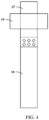
FIG. 1 is a schematic diagram of a battery according to an embodiment of this application. -
FIG. 2 is a schematic diagram of a partial cross-section, from a different perspective, of a first tab, a second tab, and an insulator shown inFIG. 1 . -
FIG. 3 is a schematic diagram of a partial structure of the battery shown inFIG. 1 . -
FIG. 4 is a schematic diagram of the insulator, a first current collector, and the first tab shown inFIG. 1 . -
FIG. 5 is a schematic diagram, from a different perspective, of the insulator, the first current collector, and the first tab shown inFIG. 4 . -
FIG. 6 is a schematic diagram of a battery according to another embodiment of this application. -
FIG. 7 is a schematic diagram of modules of an electronic device according to an embodiment of this application. -
Liquid state battery 10 Housing 11 Receiving space 111 First chamber 1111 Second chamber 1112 First sealing edge 112 Second sealing edge 113 First housing body 114 Second housing body 115 Separator 12 First end 121 Second end 122 First slurry 13 First current collector 14 Second slurry 15 Second current collector 16 First tab 17 Second tab 18 Insulator 19 Electronic device 100 - This application will be further described with reference to the accompanying drawings in the following specific embodiments.
- The following clearly and comprehensively describes the technical solutions in some embodiments of this application with reference to the accompanying drawings in some embodiments of this application. Apparently, the described embodiments are some rather than all embodiments of this application.
- Unless otherwise defined, all technical and scientific terms used herein shall have the same meanings as commonly understood by those skilled in the art to which this application belongs. The terms used herein in the specification of this application are only for description of specific embodiments, and are not intended to limit this application.
- The following describes in detail some embodiments of this application with reference to the accompanying drawings. In the absence of conflicts, the following embodiments and features in the embodiments may be combined.
- As shown in
FIG. 1 , an embodiment of this application provides aliquid state battery 10. Theliquid state battery 10 includes ahousing 11, aseparator 12, afirst slurry 13, a firstcurrent collector 14, asecond slurry 15, a secondcurrent collector 16, afirst tab 17, and asecond tab 18 having a different polarity than thefirst tab 17. Thehousing 11 encloses areceiving space 111. Theseparator 12 is disposed in thereceiving space 111 and divides thereceiving space 111 into afirst chamber 1111 and asecond chamber 1112. Thefirst slurry 13 and the firstcurrent collector 14 are received in thefirst chamber 1111. Thesecond slurry 15 and the secondcurrent collector 16 are received in thesecond chamber 1112. Thefirst tab 17 is electrically connected to the firstcurrent collector 14 and extend outside thehousing 11. Thesecond tab 18 is electrically connected to the secondcurrent collector 16 and extend outside thehousing 11. - In this embodiment, the
first slurry 13 is in a liquid or fluidized state, and thesecond slurry 15 is in a liquid or fluidized state. Thehousing 11 is a flexible housing. - In this application, the
first slurry 13, the firstcurrent collector 14, theseparator 12, thesecond slurry 15, and the secondcurrent collector 16 together constitute a liquid state electrode assembly, which is used to replace a solid state electrode assembly in a conventional battery (the solid state electrode assembly is formed by winding or lamination of a first electrode plate, a separator, and a second electrode plate), so that theliquid state battery 10 has not only energy density equal to or higher than that of the conventional battery and but also full flexibility in three dimensions. To be specific, the full flexibility in three dimensions means theliquid state battery 10 can be bent 0-180 degrees in all directions. - Referring to
FIG. 1 , two ends of thehousing 11 are sealed to form a first sealingedge 112 and a second sealingedge 113. Specifically, both thefirst tab 17 and thesecond tab 18 extend from inside thefirst sealing edge 112. Theseparator 12 is disposed between thefirst tab 17 and thesecond tab 18, so that thefirst tab 17 is electrically insulated from thesecond tab 18. - In other embodiments, both the
first tab 17 and thesecond tab 18 extend out from inside thesecond sealing edge 113; or thefirst tab 17 extends out from inside thefirst sealing edge 112, and thesecond tab 18 extends out from inside the second sealing edge 113 (referring toFIG. 6 ). - Referring to
FIG. 3 , theseparator 12 includes thefirst end 121 and thesecond end 122 away from thefirst end 121. Thefirst end 121 is disposed inside thefirst sealing edge 112, and thesecond end 122 is disposed inside thesecond sealing edge 113. - Referring to
FIG. 3 , thehousing 11 includes afirst housing body 114 and asecond housing body 115. Thefirst housing body 114 is connected to thesecond housing body 115 to form the receivingspace 111. Theseparator 12 is disposed between thefirst housing body 114 and thesecond housing body 115. As such, thefirst housing body 114 and theseparator 12 together form thefirst chamber 1111, and thesecond housing body 115 and theseparator 12 together form thesecond chamber 1112. - Refer to
FIG. 3 . The firstcurrent collector 14 is connected to a surface of thefirst housing body 114 facing theseparator 12, and the secondcurrent collector 16 is connected to a surface of thesecond housing body 115 facing theseparator 12. - Refer to
FIG. 1 . Thefirst tab 17 is welded to the firstcurrent collector 14, and thesecond tab 18 is welded to the secondcurrent collector 16. - Refer to
FIG. 1 ,FIG. 2 ,FIG. 4 , andFIG. 5 . Theliquid state battery 10 further includes aninsulator 19. Theinsulator 19 is sealed inside thefirst sealing edge 112, so that a section of thefirst tab 17 inside thefirst sealing edge 112 is electrically insulated from thefirst sealing edge 112, and a section of thesecond tab 18 inside thefirst sealing edge 112 is electrically insulated from thefirst sealing edge 112. - The
liquid state battery 10 of this application is described in detail below with examples. - Refer to
FIG 1 . Aliquid state battery 10 includes ahousing 11, aseparator 12, afirst slurry 13, a firstcurrent collector 14, asecond slurry 15, a secondcurrent collector 16, afirst tab 17, asecond tab 18 having a different polarity than thefirst tab 17, and aninsulator 19. In Example 1, thehousing 11 is a flexible housing. - Referring to
FIG. 1 , thehousing 11 includes afirst housing body 114 and asecond housing body 115. Thefirst housing body 114 is connected to thesecond housing body 115 to form a receivingspace 111. Specifically, junctions between thefirst housing body 114 and thesecond housing body 115 are sealed to form afirst sealing edge 112 and asecond sealing edge 113, respectively, in order to seal the receivingspace 111. Thefirst sealing edge 112 and thesecond sealing edge 113 face opposite directions. - In other embodiments, the
first housing body 114 and thesecond housing body 115 are integrally formed. As such, the two ends of thehousing 11 can simply be sealed to form thefirst sealing edge 112 and thesecond sealing edge 113, respectively. - The
separator 12 is disposed between thefirst housing body 114 and thesecond housing body 115 and divides the receivingspace 111 into afirst chamber 1111 and asecond chamber 1112. Specifically, thefirst slurry 13 is received in thefirst chamber 1111, and thesecond slurry 15 is received in thesecond chamber 1112. As such, while the firstcurrent collector 14 is electrically insulated from the secondcurrent collector 16 by theseparator 12, ion conduction between thefirst slurry 13 and thesecond slurry 15 is guaranteed. - In particular, the
separator 12 includes afirst end 121 and asecond end 122 away from thefirst end 121. Thefirst end 121 is disposed inside thefirst sealing edge 112, and thesecond end 122 is disposed inside thesecond sealing edge 113. As such, thefirst housing body 114 and theseparator 12 together form thefirst chamber 1111, and thesecond housing body 115 and theseparator 12 together form thesecond chamber 1112. - In Example 1, the
first slurry 13 is in a liquid or fluidized state, and thesecond slurry 15 is in a liquid or fluidized state. - The
first slurry 13 is a first slurry electrode of theliquid state battery 10. Thefirst slurry 13 is prepared in a process including: adding a gelable polymer additive to an electrolyte and then adding an active substance of a first polarity and a long-range conductive agent to make a semi-solid slurry; and injecting the semi-solid slurry into or applying the semi-solid slurry on the inside of thefirst chamber 1111 that contains the firstcurrent collector 14. - The
second slurry 15 is a second slurry electrode of theliquid state battery 10. Thesecond slurry 15 is prepared in a process including: adding a gelable polymer additive to an electrolyte and then adding an active substance of a second polarity and a long-range conductive agent to make a semi-solid slurry; and injecting the semi-solid slurry into or applying the semi-solid slurry on the inside of thesecond chamber 1112 that contains the secondcurrent collector 16. The polarity of the first slurry electrode is opposite to the polarity of the second slurry electrode. - The first
current collector 14 is connected to a surface of thefirst housing body 114 facing theseparator 12, and the secondcurrent collector 16 is connected to a surface of thesecond housing body 115 facing theseparator 12. Specifically, the firstcurrent collector 14 is electrically insulated from thefirst housing body 114, and the secondcurrent collector 16 is electrically insulated from thesecond housing body 115. In Example 1, the firstcurrent collector 14 and the secondcurrent collector 16 are both flexible current collectors. - In an embodiment, the first
current collector 14 may be bonded to thefirst housing body 114 by adhesive, and the secondcurrent collector 16 may be bonded to thesecond housing body 115 by adhesive. - The
first tab 17 is electrically connected to the firstcurrent collector 14 and extends out from inside thefirst sealing edge 112 to outside thehousing 11. Thesecond tab 18 is electrically connected to the secondcurrent collector 16 and extends out from inside thefirst sealing edge 112 to outside thehousing 11. Specifically, theseparator 12 is disposed between thefirst tab 17 and thesecond tab 18, so that thefirst tab 17 is electrically insulated from thesecond tab 18. - In Example 1, the
first tab 17 and the firstcurrent collector 14 are laser-welded together, and thesecond tab 18 and the secondcurrent collector 16 are laser-welded together. - The
insulator 19 is sealed inside thefirst sealing edge 112, so that a section of thefirst tab 17 inside thefirst sealing edge 112 is electrically insulated from thefirst sealing edge 112, and a section of thesecond tab 18 inside thefirst sealing edge 112 is electrically insulated from thefirst sealing edge 112. - In Example 1, the
liquid state battery 10 includes twosuch insulators 19. Oneinsulator 19 wraps the section of thefirst tab 17 inside thefirst sealing edge 112, and theother insulator 19 wraps the section of thesecond tab 18 inside thefirst sealing edge 112. - As shown in
FIG. 6 , Example 2 is different from Example 1 in positions of thesecond tab 18 and theinsulator 19 in Example 2. - As shown in
FIG. 6 , in Example 2, thesecond tab 18 extends out from inside thesecond sealing edge 113. Theother insulator 19 wraps a section of thesecond tab 18 inside thesecond sealing edge 113. - As shown in
FIG. 7 , this application further provides anelectronic device 100. Theelectronic device 100 contains theliquid state battery 10 described above. - Specifically, the
electronic device 100 may be a mobile electronic device, an energy storage device, an electric vehicle, a hybrid electric vehicle, or the like. The mobile electronic device may be a foldable device, a wearable electronic device, or the like. - The foregoing examples are merely intended to describe the technical solutions of this application, but not intended to constitute any limitation. Although this application has been described in detail with reference to preferred examples, persons of ordinary skill in the art should understand that modifications or equivalent replacements can be made to the technical solutions of this application, without departing from the spirit and essence of the technical solutions of this application.
Claims (10)
- A liquid state battery, comprising a housing; wherein the housing encloses a receiving space, and the liquid state battery further comprises:a separator, disposed in the receiving space and configured to divide the receiving space into a first chamber and a second chamber;a first slurry and a first current collector, received in the first chamber;a second slurry and a second current collector, received in the second chamber;a first tab, electrically connected to the first current collector and extend outside the housing; anda second tab having a different polarity than the first tab, electrically connected to the second current collector and extends outside the housing.
- The liquid state battery according to claim 1, wherein two ends of the housing are sealed to form a first sealing edge and a second sealing edge, respectively; both the first tab and the second tab extend out from inside the first sealing edge or from inside the second sealing edge; and the separator is disposed between the first tab and the second tab.
- The liquid state battery according to claim 1, wherein two ends of the housing are sealed to form a first sealing edge and a second sealing edge, respectively; the first tab extends out from inside the first sealing edge, and the second tab extends out from inside the second sealing edge; and the separator is disposed between the first tab and the second tab.
- The liquid state battery according to claim 2 or 3, wherein the separator comprises a first end and a second end away from the first end; the first end is disposed inside the first sealing edge; and the second end is disposed inside the second sealing edge.
- The liquid state battery according to claim 1, wherein the housing comprises a first housing body and a second housing body; the first housing body is connected to the second housing body so as to form the receiving space; the separator is disposed between the first housing body and the second housing body; the first housing body and the separator form the first chamber; and the second housing body and the separator form the second chamber.
- The liquid state battery according to claim 1, wherein the first current collector is connected to a surface of the first housing body facing the separator, and the second current collector is connected to a surface of the second housing body facing the separator.
- The liquid state battery according to claim 1, wherein the first tab is welded to the first current collector, and the second tab is welded to the second current collector.
- The liquid state battery according to claim 1, wherein the first slurry is in a liquid or fluidized state, and the second slurry is in a liquid or fluidized state.
- The liquid state battery according to claim 2, wherein the liquid state battery further comprises an insulator, wherein the insulator is sealed inside the first sealing edge, so that a section of the first tab inside the first sealing edge is electrically insulated from the first sealing edge, and a section of the second tab inside the first sealing edge is electrically insulated from the first sealing edge.
- An electronic device, wherein the electronic device comprises the liquid state battery according to any one of claims 1 to 9.
Applications Claiming Priority (1)
| Application Number | Priority Date | Filing Date | Title |
|---|---|---|---|
| PCT/CN2020/119521 WO2022067712A1 (en) | 2020-09-30 | 2020-09-30 | Liquid battery and electronic device having same |
Publications (2)
| Publication Number | Publication Date |
|---|---|
| EP4207425A1 true EP4207425A1 (en) | 2023-07-05 |
| EP4207425A4 EP4207425A4 (en) | 2023-10-25 |
Family
ID=78378414
Family Applications (1)
| Application Number | Title | Priority Date | Filing Date |
|---|---|---|---|
| EP20955737.0A Pending EP4207425A4 (en) | 2020-09-30 | 2020-09-30 | Liquid battery and electronic device having same |
Country Status (4)
| Country | Link |
|---|---|
| US (1) | US20230231107A1 (en) |
| EP (1) | EP4207425A4 (en) |
| CN (1) | CN113632283B (en) |
| WO (1) | WO2022067712A1 (en) |
Families Citing this family (1)
| Publication number | Priority date | Publication date | Assignee | Title |
|---|---|---|---|---|
| CN115020936B (en) * | 2022-08-09 | 2022-11-22 | 江苏时代新能源科技有限公司 | Electrode assembly and manufacturing method thereof, battery cell, battery, electrical equipment |
Family Cites Families (16)
| Publication number | Priority date | Publication date | Assignee | Title |
|---|---|---|---|---|
| CN202094228U (en) * | 2011-05-26 | 2011-12-28 | 东莞市利赛奥新能源科技有限公司 | A soft package lithium-ion battery with a bulge repair device |
| CN102315454A (en) * | 2011-08-02 | 2012-01-11 | 大连丽昌新材料有限公司 | A kind of preparation of composite collector and the application in the lithium ion flow battery thereof |
| JP2014002941A (en) * | 2012-06-19 | 2014-01-09 | Sharp Corp | Battery |
| CN107112444B (en) * | 2014-11-05 | 2021-01-26 | 24M技术公司 | Electrochemical cell with semi-solid electrode and method of making same |
| CN106159315B (en) * | 2015-04-17 | 2018-12-04 | 宁德新能源科技有限公司 | Flexible battery and preparation method thereof |
| CN107925016B (en) * | 2015-06-16 | 2021-03-16 | 株式会社半导体能源研究所 | Power storage devices and electronic equipment |
| FR3061609B1 (en) * | 2017-01-05 | 2019-05-31 | Commissariat A L'energie Atomique Et Aux Energies Alternatives | LITHIUM IONIC ELECTROCHEMICAL ACCUMULATOR WITH IMPROVED SEALING |
| US11552368B2 (en) * | 2017-02-01 | 2023-01-10 | 24M Technologies, Inc. | Systems and methods for improving safety features in electrochemical cells |
| WO2019093226A1 (en) * | 2017-11-09 | 2019-05-16 | Necエナジーデバイス株式会社 | Lithium ion secondary battery |
| WO2019136467A1 (en) * | 2018-01-08 | 2019-07-11 | 24M Technologies, Inc. | Electrochemical cells including selectively permeable membranes, systems and methods of manufacturing the same |
| CN110120542B (en) * | 2018-02-07 | 2020-12-25 | 北京好风光储能技术有限公司 | High-energy-density lithium slurry battery and working method thereof |
| KR102828489B1 (en) * | 2018-07-09 | 2025-07-03 | 24엠 테크놀로지즈, 인크. | Continuous and semi-continuous methods for manufacturing semi-solid electrodes and batteries |
| CN109103495A (en) * | 2018-08-09 | 2018-12-28 | 中南大学 | Slurry energy storage structure with heat dissipation structure |
| CN109088093B (en) * | 2018-08-09 | 2020-09-15 | 中南大学 | Static deposition type slurry battery |
| CN109088094A (en) * | 2018-08-09 | 2018-12-25 | 中南大学 | Sedimentary slurry energy storage battery with stirring structure |
| CN111261948B (en) * | 2018-11-30 | 2021-06-15 | 北京好风光储能技术有限公司 | A cylindrical lithium slurry battery and preparation method thereof |
-
2020
- 2020-09-30 WO PCT/CN2020/119521 patent/WO2022067712A1/en not_active Ceased
- 2020-09-30 CN CN202080020323.0A patent/CN113632283B/en active Active
- 2020-09-30 EP EP20955737.0A patent/EP4207425A4/en active Pending
-
2023
- 2023-03-29 US US18/127,769 patent/US20230231107A1/en active Pending
Also Published As
| Publication number | Publication date |
|---|---|
| EP4207425A4 (en) | 2023-10-25 |
| CN113632283B (en) | 2024-05-17 |
| US20230231107A1 (en) | 2023-07-20 |
| WO2022067712A1 (en) | 2022-04-07 |
| CN113632283A (en) | 2021-11-09 |
Similar Documents
| Publication | Publication Date | Title |
|---|---|---|
| US11431047B2 (en) | Feedthrough with integrated insulator | |
| KR101627631B1 (en) | Rechargeable battery and module thereof | |
| US6387566B1 (en) | Battery with laminated insulator/metal/insulator case | |
| KR101649137B1 (en) | Rechargeable battery | |
| US20240154176A1 (en) | Battery and assembling method thereof | |
| US20150303538A1 (en) | Compact battery with high energy density and power density | |
| JPS625554A (en) | Double groove type gasket for battery | |
| CN102136561A (en) | Rechargeable battery | |
| US12494535B2 (en) | Battery assembly and preparation method, battery and electric vehicle | |
| KR20230105887A (en) | Secondary Battery | |
| CN211654934U (en) | Battery and electronic device having the same | |
| EP3827468B1 (en) | Cylindrical battery cell with overmolded glass feedthrough | |
| CN217035892U (en) | Battery and electronic device | |
| US20230231107A1 (en) | Liquid state battery and electronic device containing same | |
| US11824157B2 (en) | Electrical storage device and method for making the same | |
| EP4007026A1 (en) | Rechargeable battery | |
| KR20230092267A (en) | Secondary Battery | |
| US20240014520A1 (en) | Cylindrical Battery and Battery Module | |
| US20240128609A1 (en) | Secondary battery | |
| US11652213B2 (en) | Electrode structure, method of manufacturing the same, secondary battery including the same | |
| US9065102B2 (en) | Rechargeable battery | |
| US3674565A (en) | Multicell battery having double adhesive liquid sealing window | |
| KR20140088677A (en) | asymmetric electrode plate, asymmetric electrode assembly having asymmetric electrode plate, and asymmetric secondary battery having asymmetric electrode assembly | |
| KR200211337Y1 (en) | Secondary Battery | |
| WO2023133810A1 (en) | End cover assembly, battery cell, battery and device using battery |
Legal Events
| Date | Code | Title | Description |
|---|---|---|---|
| STAA | Information on the status of an ep patent application or granted ep patent |
Free format text: STATUS: THE INTERNATIONAL PUBLICATION HAS BEEN MADE |
|
| PUAI | Public reference made under article 153(3) epc to a published international application that has entered the european phase |
Free format text: ORIGINAL CODE: 0009012 |
|
| STAA | Information on the status of an ep patent application or granted ep patent |
Free format text: STATUS: REQUEST FOR EXAMINATION WAS MADE |
|
| 17P | Request for examination filed |
Effective date: 20230329 |
|
| AK | Designated contracting states |
Kind code of ref document: A1 Designated state(s): AL AT BE BG CH CY CZ DE DK EE ES FI FR GB GR HR HU IE IS IT LI LT LU LV MC MK MT NL NO PL PT RO RS SE SI SK SM TR |
|
| A4 | Supplementary search report drawn up and despatched |
Effective date: 20230922 |
|
| RAP3 | Party data changed (applicant data changed or rights of an application transferred) |
Owner name: NINGDE AMPEREX TECHNOLOGY LTD. |
|
| RIC1 | Information provided on ipc code assigned before grant |
Ipc: H01M 4/02 20060101ALN20230918BHEP Ipc: H01M 10/052 20100101ALN20230918BHEP Ipc: H01M 50/474 20210101ALI20230918BHEP Ipc: H01M 50/557 20210101ALI20230918BHEP Ipc: H01M 50/46 20210101ALI20230918BHEP Ipc: H01M 50/186 20210101ALI20230918BHEP Ipc: H01M 50/178 20210101ALI20230918BHEP Ipc: H01M 50/105 20210101ALI20230918BHEP Ipc: H01M 4/64 20060101ALI20230918BHEP Ipc: H01M 4/36 20060101ALI20230918BHEP Ipc: H01M 10/058 20100101AFI20230918BHEP |
|
| DAV | Request for validation of the european patent (deleted) | ||
| DAX | Request for extension of the european patent (deleted) |