EP4207388A1 - Nano-silicon composite material and preparation method therefor, electrode material and battery - Google Patents
Nano-silicon composite material and preparation method therefor, electrode material and battery Download PDFInfo
- Publication number
- EP4207388A1 EP4207388A1 EP21870849.3A EP21870849A EP4207388A1 EP 4207388 A1 EP4207388 A1 EP 4207388A1 EP 21870849 A EP21870849 A EP 21870849A EP 4207388 A1 EP4207388 A1 EP 4207388A1
- Authority
- EP
- European Patent Office
- Prior art keywords
- nano
- silicon
- composite material
- coating layer
- silicon composite
- Prior art date
- Legal status (The legal status is an assumption and is not a legal conclusion. Google has not performed a legal analysis and makes no representation as to the accuracy of the status listed.)
- Pending
Links
- 239000005543 nano-size silicon particle Substances 0.000 title claims abstract description 168
- 239000002131 composite material Substances 0.000 title claims abstract description 114
- 239000007772 electrode material Substances 0.000 title claims abstract description 36
- 238000002360 preparation method Methods 0.000 title claims abstract description 24
- VYPSYNLAJGMNEJ-UHFFFAOYSA-N Silicium dioxide Chemical compound O=[Si]=O VYPSYNLAJGMNEJ-UHFFFAOYSA-N 0.000 claims abstract description 134
- 239000011247 coating layer Substances 0.000 claims abstract description 130
- 229910052814 silicon oxide Inorganic materials 0.000 claims abstract description 77
- 239000003792 electrolyte Substances 0.000 claims abstract description 35
- 239000000377 silicon dioxide Substances 0.000 claims abstract description 30
- 239000000463 material Substances 0.000 claims abstract description 29
- 235000012239 silicon dioxide Nutrition 0.000 claims abstract description 28
- 239000013078 crystal Substances 0.000 claims abstract description 27
- 229910052751 metal Inorganic materials 0.000 claims description 51
- 239000002184 metal Substances 0.000 claims description 51
- HBBGRARXTFLTSG-UHFFFAOYSA-N Lithium ion Chemical compound [Li+] HBBGRARXTFLTSG-UHFFFAOYSA-N 0.000 claims description 45
- 229910001416 lithium ion Inorganic materials 0.000 claims description 45
- XUIMIQQOPSSXEZ-UHFFFAOYSA-N Silicon Chemical compound [Si] XUIMIQQOPSSXEZ-UHFFFAOYSA-N 0.000 claims description 32
- WHXSMMKQMYFTQS-UHFFFAOYSA-N Lithium Chemical compound [Li] WHXSMMKQMYFTQS-UHFFFAOYSA-N 0.000 claims description 31
- 229910052744 lithium Inorganic materials 0.000 claims description 31
- 238000006243 chemical reaction Methods 0.000 claims description 25
- 229910052710 silicon Inorganic materials 0.000 claims description 24
- 239000010703 silicon Substances 0.000 claims description 24
- OKTJSMMVPCPJKN-UHFFFAOYSA-N Carbon Chemical compound [C] OKTJSMMVPCPJKN-UHFFFAOYSA-N 0.000 claims description 23
- 239000000203 mixture Substances 0.000 claims description 17
- 229910021645 metal ion Inorganic materials 0.000 claims description 16
- 239000003960 organic solvent Substances 0.000 claims description 16
- 238000000227 grinding Methods 0.000 claims description 14
- 239000002245 particle Substances 0.000 claims description 14
- 238000004140 cleaning Methods 0.000 claims description 13
- 229910052799 carbon Inorganic materials 0.000 claims description 12
- 229910002804 graphite Inorganic materials 0.000 claims description 11
- 239000010439 graphite Substances 0.000 claims description 11
- PAZHGORSDKKUPI-UHFFFAOYSA-N lithium metasilicate Chemical compound [Li+].[Li+].[O-][Si]([O-])=O PAZHGORSDKKUPI-UHFFFAOYSA-N 0.000 claims description 11
- 238000012545 processing Methods 0.000 claims description 11
- 239000002253 acid Substances 0.000 claims description 10
- 229910052912 lithium silicate Inorganic materials 0.000 claims description 9
- 239000007795 chemical reaction product Substances 0.000 claims description 8
- 238000002156 mixing Methods 0.000 claims description 7
- 239000007787 solid Substances 0.000 claims description 6
- 229910003002 lithium salt Inorganic materials 0.000 claims description 5
- 159000000002 lithium salts Chemical class 0.000 claims description 5
- 238000001035 drying Methods 0.000 claims description 4
- 239000010406 cathode material Substances 0.000 abstract description 22
- 238000007086 side reaction Methods 0.000 abstract description 12
- 238000005516 engineering process Methods 0.000 abstract description 6
- 238000000034 method Methods 0.000 description 17
- 238000007599 discharging Methods 0.000 description 15
- 125000004430 oxygen atom Chemical group O* 0.000 description 12
- 239000007767 bonding agent Substances 0.000 description 11
- 239000010405 anode material Substances 0.000 description 10
- 239000006258 conductive agent Substances 0.000 description 9
- 238000000605 extraction Methods 0.000 description 9
- 238000003780 insertion Methods 0.000 description 9
- 230000037431 insertion Effects 0.000 description 9
- 239000002210 silicon-based material Substances 0.000 description 9
- 239000011267 electrode slurry Substances 0.000 description 8
- 239000010410 layer Substances 0.000 description 8
- 229910007562 Li2SiO3 Inorganic materials 0.000 description 7
- 238000010586 diagram Methods 0.000 description 7
- 229920002134 Carboxymethyl cellulose Polymers 0.000 description 6
- 235000010948 carboxy methyl cellulose Nutrition 0.000 description 6
- -1 lithium hexafluorophosphate Chemical compound 0.000 description 6
- 239000004417 polycarbonate Substances 0.000 description 6
- 229920003048 styrene butadiene rubber Polymers 0.000 description 6
- XLYOFNOQVPJJNP-UHFFFAOYSA-N water Substances O XLYOFNOQVPJJNP-UHFFFAOYSA-N 0.000 description 6
- 229910001290 LiPF6 Inorganic materials 0.000 description 5
- 239000007789 gas Substances 0.000 description 5
- 230000014759 maintenance of location Effects 0.000 description 5
- 239000002243 precursor Substances 0.000 description 5
- 238000000926 separation method Methods 0.000 description 5
- LIVNPJMFVYWSIS-UHFFFAOYSA-N silicon monoxide Chemical compound [Si-]#[O+] LIVNPJMFVYWSIS-UHFFFAOYSA-N 0.000 description 5
- RYGMFSIKBFXOCR-UHFFFAOYSA-N Copper Chemical compound [Cu] RYGMFSIKBFXOCR-UHFFFAOYSA-N 0.000 description 4
- VEXZGXHMUGYJMC-UHFFFAOYSA-N Hydrochloric acid Chemical compound Cl VEXZGXHMUGYJMC-UHFFFAOYSA-N 0.000 description 4
- 239000004698 Polyethylene Substances 0.000 description 4
- 239000004743 Polypropylene Substances 0.000 description 4
- 239000002174 Styrene-butadiene Substances 0.000 description 4
- 239000006256 anode slurry Substances 0.000 description 4
- 239000006257 cathode slurry Substances 0.000 description 4
- 239000011889 copper foil Substances 0.000 description 4
- 239000008367 deionised water Substances 0.000 description 4
- 229910021641 deionized water Inorganic materials 0.000 description 4
- 238000012360 testing method Methods 0.000 description 4
- LFQSCWFLJHTTHZ-UHFFFAOYSA-N Ethanol Chemical compound CCO LFQSCWFLJHTTHZ-UHFFFAOYSA-N 0.000 description 3
- 229910001556 Li2Si2O5 Inorganic materials 0.000 description 3
- 239000002033 PVDF binder Substances 0.000 description 3
- 229910021417 amorphous silicon Inorganic materials 0.000 description 3
- 239000011248 coating agent Substances 0.000 description 3
- 238000000576 coating method Methods 0.000 description 3
- 229910021419 crystalline silicon Inorganic materials 0.000 description 3
- 230000000694 effects Effects 0.000 description 3
- 238000004146 energy storage Methods 0.000 description 3
- VNWKTOKETHGBQD-UHFFFAOYSA-N methane Chemical compound C VNWKTOKETHGBQD-UHFFFAOYSA-N 0.000 description 3
- 238000007709 nanocrystallization Methods 0.000 description 3
- 229920002981 polyvinylidene fluoride Polymers 0.000 description 3
- 239000011148 porous material Substances 0.000 description 3
- 239000000047 product Substances 0.000 description 3
- 239000002002 slurry Substances 0.000 description 3
- XKRFYHLGVUSROY-UHFFFAOYSA-N Argon Chemical compound [Ar] XKRFYHLGVUSROY-UHFFFAOYSA-N 0.000 description 2
- OIFBSDVPJOWBCH-UHFFFAOYSA-N Diethyl carbonate Chemical compound CCOC(=O)OCC OIFBSDVPJOWBCH-UHFFFAOYSA-N 0.000 description 2
- RTZKZFJDLAIYFH-UHFFFAOYSA-N Diethyl ether Chemical compound CCOCC RTZKZFJDLAIYFH-UHFFFAOYSA-N 0.000 description 2
- KMTRUDSVKNLOMY-UHFFFAOYSA-N Ethylene carbonate Chemical compound O=C1OCCO1 KMTRUDSVKNLOMY-UHFFFAOYSA-N 0.000 description 2
- KRHYYFGTRYWZRS-UHFFFAOYSA-N Fluorane Chemical compound F KRHYYFGTRYWZRS-UHFFFAOYSA-N 0.000 description 2
- WMFOQBRAJBCJND-UHFFFAOYSA-M Lithium hydroxide Chemical compound [Li+].[OH-] WMFOQBRAJBCJND-UHFFFAOYSA-M 0.000 description 2
- QAOWNCQODCNURD-UHFFFAOYSA-N Sulfuric acid Chemical compound OS(O)(=O)=O QAOWNCQODCNURD-UHFFFAOYSA-N 0.000 description 2
- 239000001768 carboxy methyl cellulose Substances 0.000 description 2
- 239000008112 carboxymethyl-cellulose Substances 0.000 description 2
- 229920006184 cellulose methylcellulose Polymers 0.000 description 2
- 238000005056 compaction Methods 0.000 description 2
- 230000008602 contraction Effects 0.000 description 2
- 239000006185 dispersion Substances 0.000 description 2
- JBTWLSYIZRCDFO-UHFFFAOYSA-N ethyl methyl carbonate Chemical compound CCOC(=O)OC JBTWLSYIZRCDFO-UHFFFAOYSA-N 0.000 description 2
- 239000001257 hydrogen Substances 0.000 description 2
- 229910052739 hydrogen Inorganic materials 0.000 description 2
- 125000004435 hydrogen atom Chemical class [H]* 0.000 description 2
- 239000007788 liquid Substances 0.000 description 2
- 238000004519 manufacturing process Methods 0.000 description 2
- 229920000515 polycarbonate Polymers 0.000 description 2
- 229920000573 polyethylene Polymers 0.000 description 2
- 229920001155 polypropylene Polymers 0.000 description 2
- 238000010298 pulverizing process Methods 0.000 description 2
- 238000005070 sampling Methods 0.000 description 2
- 239000011856 silicon-based particle Substances 0.000 description 2
- 239000007784 solid electrolyte Substances 0.000 description 2
- 239000000126 substance Substances 0.000 description 2
- IJGRMHOSHXDMSA-UHFFFAOYSA-N Atomic nitrogen Chemical compound N#N IJGRMHOSHXDMSA-UHFFFAOYSA-N 0.000 description 1
- VGGSQFUCUMXWEO-UHFFFAOYSA-N Ethene Chemical compound C=C VGGSQFUCUMXWEO-UHFFFAOYSA-N 0.000 description 1
- 239000005977 Ethylene Substances 0.000 description 1
- 229910005025 Li13Si4 Inorganic materials 0.000 description 1
- 229910010661 Li22Si5 Inorganic materials 0.000 description 1
- 229910002981 Li4.4Si Inorganic materials 0.000 description 1
- 229910011184 Li7Si3 Inorganic materials 0.000 description 1
- 229910009891 LiAc Inorganic materials 0.000 description 1
- 229910010084 LiAlH4 Inorganic materials 0.000 description 1
- JLVVSXFLKOJNIY-UHFFFAOYSA-N Magnesium ion Chemical compound [Mg+2] JLVVSXFLKOJNIY-UHFFFAOYSA-N 0.000 description 1
- GRYLNZFGIOXLOG-UHFFFAOYSA-N Nitric acid Chemical compound O[N+]([O-])=O GRYLNZFGIOXLOG-UHFFFAOYSA-N 0.000 description 1
- FKNQFGJONOIPTF-UHFFFAOYSA-N Sodium cation Chemical compound [Na+] FKNQFGJONOIPTF-UHFFFAOYSA-N 0.000 description 1
- OBNDGIHQAIXEAO-UHFFFAOYSA-N [O].[Si] Chemical compound [O].[Si] OBNDGIHQAIXEAO-UHFFFAOYSA-N 0.000 description 1
- RXBBZJPEEIUBJG-UHFFFAOYSA-N [O].[Si].[Li] Chemical compound [O].[Si].[Li] RXBBZJPEEIUBJG-UHFFFAOYSA-N 0.000 description 1
- 238000005054 agglomeration Methods 0.000 description 1
- 230000002776 aggregation Effects 0.000 description 1
- 229910045601 alloy Inorganic materials 0.000 description 1
- 239000000956 alloy Substances 0.000 description 1
- 229910052782 aluminium Inorganic materials 0.000 description 1
- XAGFODPZIPBFFR-UHFFFAOYSA-N aluminium Chemical compound [Al] XAGFODPZIPBFFR-UHFFFAOYSA-N 0.000 description 1
- 229910052786 argon Inorganic materials 0.000 description 1
- 230000002238 attenuated effect Effects 0.000 description 1
- 239000011324 bead Substances 0.000 description 1
- 230000005540 biological transmission Effects 0.000 description 1
- 230000003139 buffering effect Effects 0.000 description 1
- 230000003197 catalytic effect Effects 0.000 description 1
- 230000010261 cell growth Effects 0.000 description 1
- 230000009849 deactivation Effects 0.000 description 1
- 238000001914 filtration Methods 0.000 description 1
- 239000011888 foil Substances 0.000 description 1
- 239000011521 glass Substances 0.000 description 1
- 239000001307 helium Substances 0.000 description 1
- 229910052734 helium Inorganic materials 0.000 description 1
- SWQJXJOGLNCZEY-UHFFFAOYSA-N helium atom Chemical compound [He] SWQJXJOGLNCZEY-UHFFFAOYSA-N 0.000 description 1
- 229910052909 inorganic silicate Inorganic materials 0.000 description 1
- 150000002576 ketones Chemical class 0.000 description 1
- 239000012280 lithium aluminium hydride Substances 0.000 description 1
- XGZVUEUWXADBQD-UHFFFAOYSA-L lithium carbonate Chemical compound [Li+].[Li+].[O-]C([O-])=O XGZVUEUWXADBQD-UHFFFAOYSA-L 0.000 description 1
- 229910052808 lithium carbonate Inorganic materials 0.000 description 1
- 229910000103 lithium hydride Inorganic materials 0.000 description 1
- 229910001425 magnesium ion Inorganic materials 0.000 description 1
- 229910052754 neon Inorganic materials 0.000 description 1
- GKAOGPIIYCISHV-UHFFFAOYSA-N neon atom Chemical compound [Ne] GKAOGPIIYCISHV-UHFFFAOYSA-N 0.000 description 1
- 229910017604 nitric acid Inorganic materials 0.000 description 1
- 239000012994 photoredox catalyst Substances 0.000 description 1
- 238000001556 precipitation Methods 0.000 description 1
- 230000035484 reaction time Effects 0.000 description 1
- 238000011160 research Methods 0.000 description 1
- 150000003839 salts Chemical class 0.000 description 1
- 229910001415 sodium ion Inorganic materials 0.000 description 1
- 239000002904 solvent Substances 0.000 description 1
- 238000003756 stirring Methods 0.000 description 1
- 238000012546 transfer Methods 0.000 description 1
- 229910052724 xenon Inorganic materials 0.000 description 1
- FHNFHKCVQCLJFQ-UHFFFAOYSA-N xenon atom Chemical compound [Xe] FHNFHKCVQCLJFQ-UHFFFAOYSA-N 0.000 description 1
Images


Classifications
-
- H—ELECTRICITY
- H01—ELECTRIC ELEMENTS
- H01M—PROCESSES OR MEANS, e.g. BATTERIES, FOR THE DIRECT CONVERSION OF CHEMICAL ENERGY INTO ELECTRICAL ENERGY
- H01M4/00—Electrodes
- H01M4/02—Electrodes composed of, or comprising, active material
- H01M4/36—Selection of substances as active materials, active masses, active liquids
- H01M4/362—Composites
- H01M4/366—Composites as layered products
-
- H—ELECTRICITY
- H01—ELECTRIC ELEMENTS
- H01M—PROCESSES OR MEANS, e.g. BATTERIES, FOR THE DIRECT CONVERSION OF CHEMICAL ENERGY INTO ELECTRICAL ENERGY
- H01M4/00—Electrodes
- H01M4/02—Electrodes composed of, or comprising, active material
- H01M4/13—Electrodes for accumulators with non-aqueous electrolyte, e.g. for lithium-accumulators; Processes of manufacture thereof
- H01M4/134—Electrodes based on metals, Si or alloys
-
- H—ELECTRICITY
- H01—ELECTRIC ELEMENTS
- H01M—PROCESSES OR MEANS, e.g. BATTERIES, FOR THE DIRECT CONVERSION OF CHEMICAL ENERGY INTO ELECTRICAL ENERGY
- H01M10/00—Secondary cells; Manufacture thereof
- H01M10/05—Accumulators with non-aqueous electrolyte
- H01M10/052—Li-accumulators
- H01M10/0525—Rocking-chair batteries, i.e. batteries with lithium insertion or intercalation in both electrodes; Lithium-ion batteries
-
- H—ELECTRICITY
- H01—ELECTRIC ELEMENTS
- H01M—PROCESSES OR MEANS, e.g. BATTERIES, FOR THE DIRECT CONVERSION OF CHEMICAL ENERGY INTO ELECTRICAL ENERGY
- H01M4/00—Electrodes
- H01M4/02—Electrodes composed of, or comprising, active material
- H01M4/04—Processes of manufacture in general
- H01M4/0471—Processes of manufacture in general involving thermal treatment, e.g. firing, sintering, backing particulate active material, thermal decomposition, pyrolysis
-
- H—ELECTRICITY
- H01—ELECTRIC ELEMENTS
- H01M—PROCESSES OR MEANS, e.g. BATTERIES, FOR THE DIRECT CONVERSION OF CHEMICAL ENERGY INTO ELECTRICAL ENERGY
- H01M4/00—Electrodes
- H01M4/02—Electrodes composed of, or comprising, active material
- H01M4/13—Electrodes for accumulators with non-aqueous electrolyte, e.g. for lithium-accumulators; Processes of manufacture thereof
- H01M4/139—Processes of manufacture
- H01M4/1395—Processes of manufacture of electrodes based on metals, Si or alloys
-
- H—ELECTRICITY
- H01—ELECTRIC ELEMENTS
- H01M—PROCESSES OR MEANS, e.g. BATTERIES, FOR THE DIRECT CONVERSION OF CHEMICAL ENERGY INTO ELECTRICAL ENERGY
- H01M4/00—Electrodes
- H01M4/02—Electrodes composed of, or comprising, active material
- H01M4/36—Selection of substances as active materials, active masses, active liquids
- H01M4/362—Composites
- H01M4/364—Composites as mixtures
-
- H—ELECTRICITY
- H01—ELECTRIC ELEMENTS
- H01M—PROCESSES OR MEANS, e.g. BATTERIES, FOR THE DIRECT CONVERSION OF CHEMICAL ENERGY INTO ELECTRICAL ENERGY
- H01M4/00—Electrodes
- H01M4/02—Electrodes composed of, or comprising, active material
- H01M4/36—Selection of substances as active materials, active masses, active liquids
- H01M4/38—Selection of substances as active materials, active masses, active liquids of elements or alloys
- H01M4/386—Silicon or alloys based on silicon
-
- H—ELECTRICITY
- H01—ELECTRIC ELEMENTS
- H01M—PROCESSES OR MEANS, e.g. BATTERIES, FOR THE DIRECT CONVERSION OF CHEMICAL ENERGY INTO ELECTRICAL ENERGY
- H01M4/00—Electrodes
- H01M4/02—Electrodes composed of, or comprising, active material
- H01M4/36—Selection of substances as active materials, active masses, active liquids
- H01M4/48—Selection of substances as active materials, active masses, active liquids of inorganic oxides or hydroxides
- H01M4/483—Selection of substances as active materials, active masses, active liquids of inorganic oxides or hydroxides for non-aqueous cells
-
- H—ELECTRICITY
- H01—ELECTRIC ELEMENTS
- H01M—PROCESSES OR MEANS, e.g. BATTERIES, FOR THE DIRECT CONVERSION OF CHEMICAL ENERGY INTO ELECTRICAL ENERGY
- H01M4/00—Electrodes
- H01M4/02—Electrodes composed of, or comprising, active material
- H01M4/36—Selection of substances as active materials, active masses, active liquids
- H01M4/58—Selection of substances as active materials, active masses, active liquids of inorganic compounds other than oxides or hydroxides, e.g. sulfides, selenides, tellurides, halogenides or LiCoFy; of polyanionic structures, e.g. phosphates, silicates or borates
- H01M4/5825—Oxygenated metallic salts or polyanionic structures, e.g. borates, phosphates, silicates, olivines
-
- H—ELECTRICITY
- H01—ELECTRIC ELEMENTS
- H01M—PROCESSES OR MEANS, e.g. BATTERIES, FOR THE DIRECT CONVERSION OF CHEMICAL ENERGY INTO ELECTRICAL ENERGY
- H01M4/00—Electrodes
- H01M4/02—Electrodes composed of, or comprising, active material
- H01M4/36—Selection of substances as active materials, active masses, active liquids
- H01M4/58—Selection of substances as active materials, active masses, active liquids of inorganic compounds other than oxides or hydroxides, e.g. sulfides, selenides, tellurides, halogenides or LiCoFy; of polyanionic structures, e.g. phosphates, silicates or borates
- H01M4/583—Carbonaceous material, e.g. graphite-intercalation compounds or CFx
- H01M4/587—Carbonaceous material, e.g. graphite-intercalation compounds or CFx for inserting or intercalating light metals
-
- B—PERFORMING OPERATIONS; TRANSPORTING
- B82—NANOTECHNOLOGY
- B82Y—SPECIFIC USES OR APPLICATIONS OF NANOSTRUCTURES; MEASUREMENT OR ANALYSIS OF NANOSTRUCTURES; MANUFACTURE OR TREATMENT OF NANOSTRUCTURES
- B82Y30/00—Nanotechnology for materials or surface science, e.g. nanocomposites
-
- H—ELECTRICITY
- H01—ELECTRIC ELEMENTS
- H01M—PROCESSES OR MEANS, e.g. BATTERIES, FOR THE DIRECT CONVERSION OF CHEMICAL ENERGY INTO ELECTRICAL ENERGY
- H01M4/00—Electrodes
- H01M4/02—Electrodes composed of, or comprising, active material
- H01M2004/021—Physical characteristics, e.g. porosity, surface area
-
- H—ELECTRICITY
- H01—ELECTRIC ELEMENTS
- H01M—PROCESSES OR MEANS, e.g. BATTERIES, FOR THE DIRECT CONVERSION OF CHEMICAL ENERGY INTO ELECTRICAL ENERGY
- H01M4/00—Electrodes
- H01M4/02—Electrodes composed of, or comprising, active material
- H01M2004/026—Electrodes composed of, or comprising, active material characterised by the polarity
- H01M2004/027—Negative electrodes
-
- Y—GENERAL TAGGING OF NEW TECHNOLOGICAL DEVELOPMENTS; GENERAL TAGGING OF CROSS-SECTIONAL TECHNOLOGIES SPANNING OVER SEVERAL SECTIONS OF THE IPC; TECHNICAL SUBJECTS COVERED BY FORMER USPC CROSS-REFERENCE ART COLLECTIONS [XRACs] AND DIGESTS
- Y02—TECHNOLOGIES OR APPLICATIONS FOR MITIGATION OR ADAPTATION AGAINST CLIMATE CHANGE
- Y02E—REDUCTION OF GREENHOUSE GAS [GHG] EMISSIONS, RELATED TO ENERGY GENERATION, TRANSMISSION OR DISTRIBUTION
- Y02E60/00—Enabling technologies; Technologies with a potential or indirect contribution to GHG emissions mitigation
- Y02E60/10—Energy storage using batteries
Definitions
- This application relates to the field of battery cathode material technologies, and in particular, to a nano-silicon composite material and a preparation method thereof, an electrode material, and a battery.
- a lithium-ion battery is used as an example.
- Anode and cathode materials of the lithium-ion battery are main parts for fulfilling an energy storage function, and directly reflect energy density, cycle performance, and safety performance of an electrochemical cell.
- lithium cobaltate lithium cobaltate, LCO for short
- LCO lithium cobaltate
- a capacity brought into play of a cathode plays an important role in improving the energy density of the entire electrochemical cell.
- a silicon-based material is one of the most studied cathode materials as an alternative to graphite. Based on different degrees of reactions, silicon and lithium may produce different products, such as Li 7 Si 3 , Li 13 Si 4 , Li 22 Si 5 , and Li 12 Si 17 .
- a Li4.4Si alloy formed by inserting lithium into silicon has a theoretical gram capacity of 4200 mAh/g, and is a cathode material with a theoretically maximum capacity.
- Embodiments of this application provide a nano-silicon composite material and a preparation method thereof, an electrode material, and a battery, to resolve large volume expansion of a cathode material of a battery and a serious side reaction with an electrolyte.
- a nano-silicon composite material includes a core, a first coating layer, and a second coating layer.
- the core includes a nano-silicon crystal.
- the first coating layer covers a surface of the core.
- the first coating layer is of a porous structure.
- a material of the first coating layer includes bisilicate and silicon oxide in a deoxidized state.
- the second coating layer covers a surface of the first coating layer.
- a material of the second coating layer includes silicon dioxide in a deoxidized state.
- a chemical formula of the silicon oxide in the deoxidized state is SiO 1-m , where 0 ⁇ m ⁇ 1.
- a chemical formula of the silicon dioxide in the deoxidized state is SiO n , where 1 ⁇ n ⁇ 2.
- a ratio of silicon atoms to oxygen atoms in a molecular structure of the silicon oxide (SiO, also referred to as silicon monoxide or silicon oxide (II)) is 1:1.
- the silicon oxide in the deoxidized state has fewer oxygen atoms. Therefore, a ratio of silicon atoms to oxygen atoms in a molecular structure of the silicon oxide in the deoxidized state is 1:m, where 0 ⁇ m ⁇ 1.
- a ratio of silicon atoms to oxygen atoms in a molecular structure of the silicon dioxide (SiO 2 ) is 1:2.
- the silicon dioxide in the deoxidized state has fewer oxygen atoms.
- a ratio of silicon atoms to oxygen atoms in a molecular structure of the silicon dioxide in the deoxidized state is 1:n, where 1 ⁇ n ⁇ 2.
- the core of the nano-silicon composite material includes a nano-silicon crystal, and a size of the nano-silicon crystal is small.
- the first coating layer is of the porous structure
- the first coating layer can play a buffer function when the core expands and shrinks, to alleviate internal stress of the core, and maintain stability of the structure and integrity of the second coating layer.
- the second coating layer covers the surface of the first coating layer, and a material of the second coating layer includes the silicon dioxide in the deoxidized state, the second coating layer can block an electrolyte, and reduce or eliminate a side reaction between the electrolyte and the silicon.
- a particle size of the nano-silicon composite material is 10 nm to 150 nm.
- a particle size of the core is 10 nm to 130 nm.
- a thickness of the first coating layer is 0.1 nm to 10 nm.
- a thickness of the second coating layer is 0.1 nm to 10 nm.
- a proportion of mass of the nano-silicon crystal to mass of the nano-silicon composite material is 70% to 85%.
- a proportion a of mass of the bisilicate to mass of the nano-silicon composite material meets 0% ⁇ a ⁇ 7.5%.
- a proportion b of mass of the silicon oxide to mass of the nano-silicon composite material meets 0% ⁇ b ⁇ 7.5%.
- a proportion c of mass of the silicon dioxide to mass of the nano-silicon composite material meets 0% ⁇ c ⁇ 15%.
- the bisilicate includes lithium metasilicate.
- the nano-silicon composite material can be used in a lithium-ion battery.
- an electrode material includes a mixture of the foregoing nano-silicon composite material, graphite, and carbon.
- the electrode material has same technical effect as that in the foregoing embodiment, and details are not described herein again.
- a proportion of mass of the nano-silicon composite material to mass of the electrode material is 3% to 60%.
- a battery including an electrochemical cell, a corresponding connecting accessory, and a circuit.
- the electrochemical cell includes an anode, a cathode, an electrolyte, and a separator.
- the cathode includes the foregoing electrode material.
- the battery has same technical effect as that in the foregoing embodiment, and details are not described herein again.
- a preparation method of a nano-silicon composite material includes the following steps: performing processing on silicon oxide and a metal source to obtain a mixture of nano-silicon, bisilicate, and silicon oxide in a deoxidized state; and performing acid cleaning on and grinding the mixture of the nano-silicon, the bisilicate, and the silicon oxide in the deoxidized state to obtain a nano-silicon composite material.
- the nano-silicon composite material includes a core, a first coating layer covering a surface of the core, and a second coating layer covering a surface of the first coating layer.
- the core includes a nano-silicon crystal.
- the first coating layer is of a porous structure.
- a material of the first coating layer includes bisilicate and silicon oxide in a deoxidized state.
- a material of the second coating layer includes silicon dioxide in a deoxidized state.
- the core of the prepared nano-silicon composite material includes a nano-silicon crystal, and a size of the nano-silicon crystal is small.
- a metal ion for example, a lithium ion
- this can effectively reduce volume expansion, reduce mechanical fatigue of a material, and prolong a cycle life.
- the first coating layer is of the porous structure, the first coating layer can play a buffer function when the core expands and shrinks, to alleviate internal stress of the core, and maintain stability of the structure and integrity of the second coating layer.
- the second coating layer covers the surface of the first coating layer, and a material of the second coating layer includes the silicon dioxide in the deoxidized state, the second coating layer can block an electrolyte, and reduce or eliminate a side reaction between the electrolyte and the silicon.
- the performing processing on silicon oxide and a metal source includes: evenly mixing the silicon oxide and the metal source in a solid state at a preset ratio, or introducing the metal source in a vapor state into the silicon oxide at a preset ratio, and performing roasting in a high temperature furnace in an inert atmosphere or a reducing atmosphere.
- this method may be used to perform processing on the silicon oxide and the metal source.
- a roasting temperature is 300°C to 900°C.
- the metal source is an organic solvent containing a metal ion.
- the performing processing on silicon oxide and a metal source includes: mixing, at a preset ratio, the silicon oxide and the organic solvent containing the metal ion, and reacting in an inert atmosphere or a reducing atmosphere; and cleaning and drying a reaction product.
- this method may be used to perform processing on the silicon oxide and the metal source.
- a reaction temperature is less than 200°C.
- the preset ratio is a molar ratio that is of a metal element in the metal source to a silicon element in the silicon oxide and that is 0.1 to 1.0.
- the metal source includes a lithium source, and the lithium source includes metal lithium or a lithium salt. Because the lithium source includes the metal lithium or the lithium salt, the prepared nano-silicon composite material may be used in a lithium-ion battery.
- the organic solvent containing the metal ion includes an organic solvent containing a lithium ion. Because the organic solvent containing the metal ion includes the organic solvent containing the lithium ion, the prepared nano-silicon composite material may be used in a lithium-ion battery.
- the battery may be a lithium-ion battery, a sodium-ion battery, a magnesium-ion battery, or the like.
- a specific form of the battery is not specially limited in embodiments of this application.
- a lithium-ion battery is used as an example in the following for description.
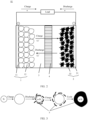
- a main structure of the battery 01 includes an electrochemical cell, a corresponding connecting accessory (for example, a load), and a circuit.
- the electrochemical cell includes an anode 1, a cathode 2, an electrolyte 3, and a separator 4.
- the anode 1 includes an anode collector (also referred to as an anode plate) 11 and anode slurry coated on a surface of the anode collector 11.
- the anode slurry includes an anode material 12, a conductive agent, a bonding agent, and the like.
- the anode collector 11 may be, for example, aluminum foil.
- the anode material 12 may be, for example, lithium cobaltate.
- the conductive agent in the anode slurry may be, for example, super P (super P, SP).
- the bonding agent in the anode slurry may be, for example, polyvinylidene fluoride (polyvinylidene fluoride, PVDF).
- the cathode 2 includes a cathode collector (also referred to as a cathode plate) 21 and cathode slurry coated on a surface of the cathode collector 21.
- the cathode slurry includes a cathode material 22, a conductive agent, a bonding agent, and the like.
- the cathode collector 21 may be, for example, copper foil.
- the conductive agent in the cathode slurry may be, for example, super P.
- the bonding agent in the cathode slurry may be, for example, carboxymethyl cellulose (carboxymethyl cellulose, CMC) and styrene-butadiene rubber (styrene-butadiene rubber, SBR).
- a lithium ion may be inserted into and extracted from the anode material 12 and the cathode material 22 to implement energy storage and release.
- the electrolyte 3 is a carrier for lithium ion transmission between the anode 1 and the cathode 2.
- the lithium ion can pass through the non-conductive separator 4, but the non-conductive separator 4 can separate the anode 1 and the cathode 2 to prevent short circuit.
- a working principle of the lithium-ion battery is as follows: During charging, Li + in the anode material 12 and Li + in the electrolyte 3 aggregate to the cathode 2, to obtain an electron, which is restored to Li and inserted into the cathode material 22 of the cathode 2. During discharging, the Li inserted in the cathode material 22 of the cathode 2 loses the electron and enters the electrolyte 3, and the Li + in the electrolyte 3 moves towards the anode 1. It can be learned based on the foregoing working principle of the lithium-ion battery that the anode material 12 and the cathode material 22 are main parts for fulfilling an energy storage function, and directly reflect energy density, cycle performance, and safety performance of the electrochemical cell.
- lithium cobaltate has reached maximum usage of the commercial anode material 12.
- a maximum voltage of the lithium cobaltate is 4.4 V, and a compaction density is 4.2 g/cm 3 . Therefore, a capacity brought into play of the cathode material 22 is one of key factors for improving the energy density of the entire electrochemical cell.
- the silicon-based material has a high gram capacity
- the silicon-based material is usually used as a cathode material of a battery.
- the silicon-based material undergoes severe volume expansion and contraction in a lithium insertion and extraction reaction process, causing damage and pulverization of a structure of the electrode material.
- a silicon surface and the electrolyte continuously generate a new SEI film, causing electrolyte exhaustion and rapid battery capacity attenuation.
- nanocrystallization is usually used to alleviate volume expansion of silicon.
- nanocrystallization causes a high specific surface area with a feature of high probability of agglomeration and low probability of dispersion, a large contact area with the electrolyte, a serious side reaction, fast deactivation in a silicon material, fast consumption of the electrolyte, and the like.
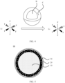
- FIG. 3 In a charging and discharging process of nano-silicon, a surface of silicon reacts with an electrolyte to form a side reaction product 5. After a plurality of times of charging and discharging, the surface of silicon is covered by the formed side reaction product 5.
- the nano-silicon is crystalline silicon before the first charging and discharging, and after the first charging and discharging, amorphous silicon (amorphous Si, a-Si) is formed.
- a coating layer for example, a carbon (C) coating layer
- Si nano-silicon
- a coating layer is further disposed on a surface of a nano-silicon (Si) cathode material.
- C carbon
- pores of the nano-silicon (Si) cathode material cannot truly alleviate the side reaction between the silicon and the electrolyte.
- a latest research result shows that catalytic effect of carbon coating accelerates a reaction between the silicon and lithium hexafluorophosphate (LiPF 6 ) in the electrolyte, thereby causing a loss of active silicon and capacity attenuation.
- an embodiment of this application provides an electrode material.
- the electrode material may be used as the cathode material 22 in the cathode 2 of the battery 01.
- the electrode material includes a mixture of a nano-silicon composite material, graphite, and carbon, and the electrode material may also be referred to as a nano silicon/graphite/carbon composite material.
- a proportion of mass of the nano-silicon composite material in the electrode material to mass of the electrode material is 3% to 60%.
- a proportion of the mass of the nano-silicon composite material to the mass of the electrode material may be 3%, 20%, 40%, or 60%.
- a particle size of the nano-silicon composite material is 10 nm to 150 nm.
- the particle size of the nano-silicon composite material may be 10 nm, 30 nm, 60 nm, 100 nm, or 150 nm.
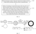
- the nano-silicon composite material 02 includes a core 10, a first coating layer 20, and a second coating layer 30.
- the core 10 includes a nano-silicon crystal (Si cluster), and the nano-silicon crystal includes a plurality of nano-silicon atoms.
- the first coating layer 20 covers a surface of the core 10.
- the first coating layer 20 is of a porous structure.
- a material of the first coating layer 20 includes bisilicate and silicon oxide (SiO 1-m , 0 ⁇ m ⁇ 1) in a deoxidized state.
- the second coating layer 30 covers a surface of the first coating layer 20.
- a material of the second coating layer 30 includes silicon dioxide (SiO n , 1 ⁇ n ⁇ 2) in a deoxidized state.
- a ratio of silicon atoms to oxygen atoms in a molecular structure of the silicon oxide is 1:1.
- the silicon oxide in the deoxidized state has fewer oxygen atoms. Therefore, a ratio of silicon atoms to oxygen atoms in a molecular structure of the silicon oxide in the deoxidized state is 1:m, where 0 ⁇ m ⁇ 1.
- a ratio of silicon atoms to oxygen atoms in a molecular structure of the silicon dioxide (SiO 2 ) is 1:2.
- a particle size of the core 10 is 10 nm to 130 nm.
- the particle size of the core 10 may be 10 nm, 20 nm, 50 nm, 100 nm, or 130 nm.
- the core 10 may be, for example, in a spherical shape, a spherical-like shape, or the like.
- a thickness of the first coating layer 20 may be correspondingly adjusted according to the particle size of the core 10.
- a thickness of the first coating layer 20 is set, it needs to be ensured that the first coating layer 20 can play a buffering function, and it needs to be ensured that lithium ion insertion and extraction reactions of the core 10 in a charging and discharging process is not affected.
- a thickness of the first coating layer 20 is 0.1 nm to 10 nm.
- the thickness of the first coating layer 20 may be 0.1 nm, 1 nm, 5 nm, or 10 nm.
- a thickness of the second coating layer 30 may also be correspondingly adjusted according to the particle size of the core 10.
- the thickness of the second coating layer 30 it needs to be ensured that the second coating layer 30 can block a reaction between the electrolyte and silicon, and it needs to be ensured that lithium ion insertion and extraction reactions of the core 10 in a charging and discharging process is not affected.
- a thickness of the second coating layer 20 is 0.1 nm to 10 nm.
- the thickness of the second coating layer 20 may be 0.1 nm, 1 nm, 5 nm, or 10 nm.
- the first coating layer 20 covers the surface of the core 10
- the second coating layer 30 covers the surface of the first coating layer 20
- a shape of the first coating layer 20 and a shape of the second coating layer 30 are related to a shape of the core 10.
- the core 10 is in a spherical shape
- a cross section of the first coating layer 20 and a cross section of the second coating layer 30 are in a circular shape.
- a proportion of mass of the nano-silicon crystal to mass of the nano-silicon composite material is 70% to 85%.
- a ratio of moles of the nano-silicon crystal to a sum of moles of the bisilicate, the silicon oxide in the deoxidized state, and the silicon dioxide in the deoxidized state is 7:3 to 4:1.
- a proportion of the mass of the nano-silicon crystal to the mass of the nano-silicon composite material may be 70%, 80%, or 85%.
- a proportion a of mass of the bisilicate in the first coating layer 20 to mass of the nano-silicon composite material meets 0 ⁇ a ⁇ 7.5%.
- a proportion of the mass of the bisilicate to the mass of the nano-silicon composite material may be 2%, 5%, or 7.5%.
- the bisilicate includes lithium metasilicate (Li 2x Si y O x+2y , where x and y are positive integers).
- the battery provided in this embodiment of this application is a lithium-ion battery.
- the lithium-ion battery has high energy density, a fast charge and discharge speed, a long service life, and low self-discharge.
- the foregoing lithium metasilicate may be, for example, at least one of Li 2 SiO 3 , Li 2 Si 2 O 5 , or Li 4 SiO 4 .
- the nano-silicon composite material needs to be mixed with graphite and carbon to form an electrode material.
- the electrode material is mixed with a conductive agent, a bonding agent, and the like to form slurry and is coated on the cathode collector 21.
- Li 2 SiO 3 is difficult to dissolve in water, and is not affected by a water-based slurry preparation process in a slurry preparation process. Therefore, in some examples, the lithium metasilicate is Li 2 SiO 3 .
- a proportion b of mass of the silicon oxide in the first coating layer 20 to mass of the nano-silicon composite material meets 0% ⁇ b ⁇ 7.5%.
- a proportion of the mass of the silicon oxide to the mass of the nano-silicon composite material may be 2%, 5%, or 7.5%.
- a proportion of the mass of the bisilicate to the mass of the nano-silicon composite material may be the same as or different from a proportion of the mass of the silicon oxide to the mass of the nano-silicon composite material.
- a proportion c of mass of the silicon dioxide to mass of the nano-silicon composite material meets 0% ⁇ c ⁇ 15%.
- a proportion of the mass of the silicon dioxide to the mass of the nano-silicon composite material may be 1%, 5%, 10%, or 15%.
- the nano-silicon composite material 02 includes a core 10, a first coating layer 20, and a second coating layer 30.
- the core 10 includes a nano-silicon crystal.
- the first coating layer 20 covers a surface of the core 10.
- the first coating layer 20 is of a porous structure.
- a material of the first coating layer 20 includes bisilicate and silicon oxide in a deoxidized state.
- the second coating layer 30 covers a surface of the first coating layer 20.
- a material of the second coating layer 30 includes silicon dioxide in a deoxidized state.
- the core 10 of the nano-silicon composite material 02 includes a nano-silicon crystal, and a size of the nano-silicon crystal is small.
- the first coating layer 20 is of the porous structure, the first coating layer 20 can play a buffer function when the core 10 expands and shrinks, to alleviate internal stress of the core 10, and maintain stability of the structure and integrity of the second coating layer 30.
- the second coating layer 30 covers the surface of the first coating layer 20, and the material of the second coating layer 30 includes the silicon dioxide in the deoxidized state, the second coating layer 30 can block an electrolyte, and reduce or eliminate a side reaction between the electrolyte and silicon.
- An embodiment of this application further provides a preparation method of a nano-silicon composite material 02, which may be used to prepare the nano-silicon composite material 02.
- the preparation method of a nano-silicon composite material 02 includes the following steps.
- S100 Perform processing on silicon oxide and a metal source to obtain a mixture of nano-silicon, bisilicate, and silicon oxide in a deoxidized state.
- the silicon oxide and the metal source may be processed based on a form of the metal source.
- the following provides examples of three processing manners of the silicon oxide and the metal source.
- the silicon oxide and the metal source may be processed in a manner 1.
- the manner 1 is as follows: The silicon oxide and the metal source in the solid state are evenly mixed at a preset ratio, and then roasted in a high temperature furnace in an inert atmosphere or a reducing atmosphere.
- the silicon oxide and the metal source in the solid state may be evenly mixed at the preset ratio, transferred to a saggar, and then transferred from the saggar to the high temperature furnace in the inert atmosphere or the reducing atmosphere for roasting.
- the silicon oxide and the metal source may be processed in a manner 2.
- the manner 2 is as follows: The metal source in a vapor state is introduced into the silicon oxide at a preset ratio, and both are roasted in a high temperature furnace in an inert atmosphere or a reducing atmosphere.
- a roasting temperature is 300°C to 900°C.
- the roasting temperature may be, for example, 300°C, 500°C, 700°C, or 900°C.
- the high temperature furnace used in the foregoing manner 1 and manner 2 may be, for example, a vacuum furnace, a box-type furnace, a rotary furnace, or a tube furnace.
- the metal source is simple metal or a salt that contains a metal ion.
- the metal source includes a lithium source, and the lithium source includes metal lithium or a lithium salt.
- the lithium salt includes one or more of LiH, LiAlH 4 , Li 2 CO 3 , LiNOs, LiAc, and LiOH.
- the metal source When the metal source is in a liquid state, the metal source is an organic solvent including a metal ion, and the silicon oxide and the metal source may be processed in a manner 3.
- the manner 3 is as follows: The silicon oxide and the organic solvent containing the metal ion are mixed at a preset ratio, and reacted in an inert atmosphere or a reducing atmosphere; and then a reaction product is cleaned and dried.
- a reaction temperature is less than 200°C.
- reaction temperature may be 20°C, 50°C, 100°C, or 150°C.
- the organic solvent may be, for example, at least one of alcohol, ether, or ketone.
- reaction product may be cleaned by using deionized water, to remove the organic solvent.
- the organic solvent containing the metal ion includes an organic solvent including a lithium ion.
- the inert atmosphere in the foregoing manner 1, manner 2, and manner 3 may be, for example, at least one of argon (Ar), helium (He), neon (Ne), nitrogen (N 2 ), or xenon (Xe).
- the reducing atmosphere may be, for example, at least one of hydrogen (H 2 ), ethylene (C 2 H 4 ), or methane (CH 4 ).
- the preset ratio in the foregoing manner 1, manner 2, and manner 3 is a molar ratio that is of a metal element in the metal source to a silicon element in the silicon oxide and that is 0.1 to 1.0.
- 0.1 ⁇ nX/nSi ⁇ 1.0 where X represents the metal element.
- a molar ratio of a lithium element in the lithium source to the silicon element in the silicon oxide is 0.1 to 1.0.
- a structure of a product formed by reaction may be adjusted by controlling a reaction condition (for example, the ratio of the metal element in the metal source to the silicon element in the silicon oxide, and the reaction temperature), to convert the silicon oxide into a silicon-oxygen compound (for example, a lithium-silicon-oxygen compound Li 2 SiO 3 ) that is specifically formed and that contains a metal ion.
- a reaction condition for example, the ratio of the metal element in the metal source to the silicon element in the silicon oxide, and the reaction temperature
- a silicon-oxygen compound for example, a lithium-silicon-oxygen compound Li 2 SiO 3
- a type of lithium metasilicate may be adjusted by controlling a ratio, a reaction temperature, and the like of the lithium element in the lithium source and the silicon element in the silicon oxide.
- a lithium-rich reaction and a low-temperature reaction are conducive to forming Li 2 SiO 3 .
- S101 Perform acid cleaning on and grind the mixture of the nano-silicon, the bisilicate, and the silicon oxide in the deoxidized state to obtain a nano-silicon composite material 02, where the nano-silicon composite material 02 includes a core 10, a first coating layer 20 covering a surface of the core 10, and a second coating layer 30 covering a surface of the first coating layer 20, the core 10 includes a nano-silicon crystal, the first coating layer 20 is of a porous structure, a material of the first coating layer 20 includes bisilicate and silicon oxide in a deoxidized state, and a material of the second coating layer 30 includes silicon dioxide in a deoxidized state.
- acid cleaning solution selected during acid cleaning may be, for example, one or more of sulfuric acid, hydrochloric acid, nitric acid, and hydrofluoric acid.
- An objective of acid cleaning is to remove a specific phase from bisilicate to form a pore.
- the selected acid cleaning solution should be highly corrosive and oxidized, and can react to the material in a targeted manner.
- the bisilicate obtained in step S100 includes Li 2 SiO 3 , Li 2 Si 2 O 5 , or the like. Li 2 Si 2 O 5 may be removed in a targeted manner through acid cleaning, to form a pore.
- the remaining bisilicate is mainly Li 2 SiO 3 .
- the acid-cleaned precursor may be sent into a grinding groove of a grinding machine.
- the grinding groove is filled with a proper quantity of grinding media, for example, glass beads.
- a dispersed blade in the grinding machine rotates at a high speed, so that the grinding media collides with the acid-cleaned precursor, thereby achieving dispersion effect, to further reduce a particle size of the acid-cleaned precursor.
- Grinding can reduce the particle size of the acid-cleaned precursor, and can form silicon dioxide in a deoxidized state on a surface of the nano-silicon composite material, that is, form the second coating layer 30.
- the reaction product and the grinding media may be separated and discharged by using a separation method.
- the separation method may be, for example, at least one of a precipitation separation method, a centrifuge separation method, or a solvent separation method.
- a thickness of the first coating layer 20, and a thickness of the second coating layer 30 refer to the foregoing embodiments, and details are not described herein again.
- a mass ratio of the nano-silicon crystal, the bisilicate, the silicon oxide, and the silicon dioxide refer to the foregoing embodiments, and details are not described herein again.
- An embodiment of this application provides a preparation method of a nano-silicon composite material 02.
- the prepared nano-silicon composite material 02 includes a core 10, a first coating layer 20, and a second coating layer 30.
- the core 10 includes a nano-silicon crystal.
- the first coating layer 20 covers a surface of the core 10.
- the first coating layer 20 is of a porous structure.
- a material of the first coating layer 20 includes bisilicate and silicon oxide in a deoxidized state.
- the second coating layer 30 covers a surface of the first coating layer 20.
- a material of the second coating layer 30 includes silicon dioxide in a deoxidized state.
- the core 10 of the nano-silicon composite material 02 includes a nano-silicon crystal, and a size of the nano-silicon crystal is small.
- the first coating layer 20 is of the porous structure, the first coating layer 20 can play a buffer function when the core 10 expands and shrinks, to alleviate internal stress of the core 10, and maintain stability of the structure and integrity of the second coating layer 30.
- the second coating layer 30 covers the surface of the first coating layer 20, and the material of the second coating layer 30 includes the silicon dioxide in the deoxidized state, the second coating layer 30 can block an electrolyte, and reduce or eliminate a side reaction between the electrolyte and silicon.
- An embodiment of this application further provides a preparation method of an electrode material, including: mixing the nano-silicon composite material 02 prepared in step S100 and step S101 with graphite and carbon, to obtain an electrode material.
- a proportion of mass of the nano-silicon composite material 02 to a sum of the mass of the nano-silicon composite material 02, mass of graphite, and mass of carbon is 3% to 60%.
- An embodiment of this application further provides a preparation method of an electrode slurry, including: dispersing and evenly stirring the foregoing prepared electrode material, a conductive agent, and a bonding agent in deionized water, to obtain electrode slurry.
- the conductive agent may be, for example, SP.
- the bonding agent may be, for example, SBR and CMC.
- An embodiment of this application further provides a preparation method of a cathode, including: coating a surface of a cathode collector with the foregoing prepared electrode slurry, and drying the electrode slurry to obtain a cathode (also referred to as a cathode plate).
- the cathode collector may be, for example, copper foil.
- the following provides a specific embodiment to describe in detail a process of preparing a nano-silicon composite material 02, an electrode material, and a lithium-ion battery.
- S200 Weigh silicon oxide (SiO) and a solid-state lithium source, where a molar ratio nLi/nSi of a lithium element in the lithium source to a silicon element in the silicon oxide is 0.1 to 1.0, fully and evenly mix the weighed silicon oxide and the solid-state lithium source under protection of an Ar gas atmosphere or a mixture atmosphere of hydrogen (H 2 ) and Ar gas, and then transfer the evenly mixed silicon oxide and lithium source to a high temperature furnace protected by an inert atmosphere for high temperature roasting at 500°C to 900°C.
- a reaction time period is 5 to 48 hours. After a reaction is completed, pre-lithiumized silicon oxide may be obtained.
- Step S200 may also be referred to as a pre-lithiumization process.
- S201 Weigh a mixture of 5 g of nano-silicon, lithium metasilicate, and silicon oxide in a deoxidized state, add excessive 1 mol/L hydrochloric acid for mixing, perform mixing at a speed of 200 r/min, perform a reaction for 12 to 24 hours, perform filtering and cleaning, and perform drying in a vacuum for 6 to 12 hours at 80°C.
- a dried product is transferred into a grinding machine, ground for 24 to 48 hours under protection of ethanol and Ar gas, filtered, cleaned, and dried to obtain the nano-silicon composite material 02.
- a core 10 of the nano-silicon composite material 02 includes a nano-silicon crystal.
- the first coating layer 20 covers a surface of the core 10.
- a material of the first coating layer 20 includes lithium metasilicate (Li 2 SiO 3 ) and silicon oxide (SiO 1-m , 0 ⁇ m ⁇ 1) in a deoxidized state.
- a second coating layer 30 covers a surface of the first coating layer 20.
- a material of the second coating layer 30 includes silicon dioxide (SiOn, 1 ⁇ n ⁇ 2) in a deoxidized state.
- Step S201 may also be referred to as an acid cleaning and grinding process.
- Performance of the prepared nano-silicon composite material 02 is detected.
- a gram capacity of the nano-silicon composite material 02 is 2000 to 3500 mAh/g, and initial coulomb efficiency is 80% to 90%. It can be learned that the nano-silicon composite material 02 prepared in this embodiment of this application has a high gram capacity, and initial coulomb efficiency is high.
- the nano-silicon composite material 02 prepared by using S200 and S201 is compared with existing nano-silicon (the nano-silicon is a crystalline silicon particle with a diameter of nanometers, for example, a crystalline silicon particle with a diameter of less than 5 nm).
- a comparison result is shown in Table 1.
- Table 1 Particle size (d50) Gram capacity First-time efficiency Nano-silicon composite material 50 nm 3000 mAh/g 86% Nano-silicon 50 nm 2800 mAh/g 85%
- the nano-silicon composite material 02 prepared in this embodiment of this application has advantages in terms of a gram capacity and efficiency.
- Specific steps for preparing an electrode material are as follows: S300: Mix, based on a mass ratio of 40%:50%:10%, a nano-silicon composite material 02, graphite, and carbon that are prepared by using S200 and S201, to obtain the electrode material.
- the electrode material may be used as a cathode material.
- Specific steps for preparing a lithium-ion battery are as follows: S400: Disperse and evenly mix, based on a mass ratio of 95:0.3:3.2:1.5, the electrode material, a conductive agent SP, a bonding agent SBR, and a bonding agent CMC that are prepared by using S300 in deionized water, to obtain electrode slurry. Next, a surface of copper foil is coated with electrode slurry, and dried at 85°C, to obtain a cathode (namely, a cathode plate) 2.
- the prepared cathode 2 is used with a lithium cobaltate anode (namely, an anode plate), and a mixture of 1 mol/L of ethylene carbonate (ethylene carbonate, LiPF 6 /EC), polycarbonate (polycarbonate, PC), diethyl carbonate (diethyl carbonate, DEC), ethyl methyl carbonate (ethyl methyl carbonate, EMC) is selected as an electrolyte.
- a volume ratio of LiPF 6 /EC, PC, DEC, and EMC is 1:0.3:1:1.
- a three-layer separator is used to manufacture a soft pack battery of about 3.7 Ah.
- An intermediate layer is made of polyethylene (polyethylene, PE).
- Two side layers are made of polypropylene (polypropylene, PP).
- a thickness of the three-layer separator is 10 ⁇ m.
- Electrode material prepared by using the nano-silicon, a conductive agent SP, a bonding agent SBR, and a bonding agent CMC are dispersed in deionized water at a mass ratio of 95:0.3:3.2:1.5, and are evenly stirred to obtain electrode slurry.
- a surface of copper foil is coated with electrode slurry, and dried at 85°C to obtain a cathode 2.
- the prepared cathode 2 is used with a lithium cobaltate anode, and a mixture of 1 mol/L of LiPF 6 /EC, PC, DEC, and EMC is selected as an electrolyte.
- a volume ratio of LiPF 6 /EC, PC, DEC, and EMC is 1:0.3:1:1.
- a three-layer separator is used to manufacture a soft pack battery of about 3.7 Ah.
- An intermediate layer is made of PE.
- Two side layers are made of PP.
- a thickness of the three-layer separator is 10 ⁇ m.
- FIG. 8 shows a plurality of sampling points obtained by testing two lithium ion soft pack batteries prepared by using the foregoing nano-silicon composite material 02 and a plurality of sampling points obtained by testing two lithium ion soft pack batteries prepared by using nano-silicon.
- a horizontal axis represents a quantity of cycles of charging and discharging.
- a quantity of cycles is 500 weeks, indicating that an electrochemical cell may be charged and discharged for 500 times.
- a vertical axis indicates a capacity retention rate of the electrochemical cell.
- the cycle performance may be indicated by a quantity of cycles of charging and discharging and a capacity retention rate of an electrochemical cell. When quantities of cycles are the same, a higher capacity retention rate of the electrochemical cell indicates better cycle performance of the electrochemical cell of the lithium-ion battery.
- the electrochemical cell of the lithium-ion battery prepared by using the nano-silicon composite material 02 has excellent cycle performance.
- a capacity retention rate of the electrochemical cell is 80%.
- the capacity retention rate of the electrochemical cell of the lithium-ion battery prepared by using the nano-silicon is attenuated to 80%.
- electrochemical cell expansion rates of the lithium-ion battery prepared by using the nano-silicon composite material 02 and the lithium-ion battery prepared by using the nano-silicon are respectively tested to be 6% and 13%.
- the lithium-ion battery prepared by using the foregoing nano-silicon composite material 02 improves the cycle performance of the electrochemical cell and reduce the expansion rate.
- the core 10 using the nano-silicon composite material 02 includes a nano-silicon crystal, and the nano-silicon crystal has a small size, so that volume expansion can be reduced.
- the first coating layer 20 of the nano-silicon composite material 02 is of a porous structure, and can play a buffer function when the core 10 expands and shrinks, to maintain stability of the structure, reduce volume expansion, and improve cycle performance of the electrochemical cell.
- the second coating layer 30 of the nano-silicon composite material 02 can block an electrolyte, reduce or eliminate a side reaction between the electrolyte and silicon, and can also improve cycle performance of an electrochemical cell.
Landscapes
- Chemical & Material Sciences (AREA)
- Chemical Kinetics & Catalysis (AREA)
- Electrochemistry (AREA)
- General Chemical & Material Sciences (AREA)
- Engineering & Computer Science (AREA)
- Composite Materials (AREA)
- Manufacturing & Machinery (AREA)
- Materials Engineering (AREA)
- Inorganic Chemistry (AREA)
- Crystallography & Structural Chemistry (AREA)
- Battery Electrode And Active Subsutance (AREA)
- Silicon Compounds (AREA)
Abstract
Description
- This application claims priority to
Chinese Patent Application No. 202011034975.8, filed with the China National Intellectual Property Administration on September 27, 2020 - This application relates to the field of battery cathode material technologies, and in particular, to a nano-silicon composite material and a preparation method thereof, an electrode material, and a battery.
- A lithium-ion battery is used as an example. Anode and cathode materials of the lithium-ion battery are main parts for fulfilling an energy storage function, and directly reflect energy density, cycle performance, and safety performance of an electrochemical cell. Because lithium cobaltate (lithium cobaltate, LCO for short), as an anode material, has reached a maximum limit of use (4.4 V, compaction density: 4.2 g/cm3) of the anode material, a capacity brought into play of a cathode plays an important role in improving the energy density of the entire electrochemical cell.
- However, an actual gram capacity of a graphite cathode of a conventional lithium-ion battery is 360 mAh/g, which is close to a theoretical value (372 mAh/g). Therefore, it is necessary to develop a new high-capacity cathode material. A silicon-based material is one of the most studied cathode materials as an alternative to graphite. Based on different degrees of reactions, silicon and lithium may produce different products, such as Li7Si3, Li13Si4, Li22Si5, and Li12Si17. A Li4.4Si alloy formed by inserting lithium into silicon has a theoretical gram capacity of 4200 mAh/g, and is a cathode material with a theoretically maximum capacity. However, a silicon-based material shown in
FIG. 1 undergoes severe volume expansion (0% to 300%) and contraction in a lithium insertion and extraction reaction process, causing damage and pulverization of a structure of an electrode material; and a silicon surface and an electrolyte continuously generate a new solid electrolyte interface (solid electrolyte interface, SEI) film, resulting in electrolyte exhaustion and rapid battery capacity attenuation. - Embodiments of this application provide a nano-silicon composite material and a preparation method thereof, an electrode material, and a battery, to resolve large volume expansion of a cathode material of a battery and a serious side reaction with an electrolyte.
- To achieve the foregoing objective, this application uses the following technical solutions.
- According to a first aspect, a nano-silicon composite material is provided. The nano-silicon composite material includes a core, a first coating layer, and a second coating layer. The core includes a nano-silicon crystal. The first coating layer covers a surface of the core. The first coating layer is of a porous structure. A material of the first coating layer includes bisilicate and silicon oxide in a deoxidized state. The second coating layer covers a surface of the first coating layer. A material of the second coating layer includes silicon dioxide in a deoxidized state. For example, a chemical formula of the silicon oxide in the deoxidized state is SiO1-m, where 0 < m < 1. A chemical formula of the silicon dioxide in the deoxidized state is SiOn, where 1 < n < 2. A ratio of silicon atoms to oxygen atoms in a molecular structure of the silicon oxide (SiO, also referred to as silicon monoxide or silicon oxide (II)) is 1:1. The silicon oxide in the deoxidized state has fewer oxygen atoms. Therefore, a ratio of silicon atoms to oxygen atoms in a molecular structure of the silicon oxide in the deoxidized state is 1:m, where 0 < m < 1. A ratio of silicon atoms to oxygen atoms in a molecular structure of the silicon dioxide (SiO2) is 1:2. The silicon dioxide in the deoxidized state has fewer oxygen atoms. Therefore, a ratio of silicon atoms to oxygen atoms in a molecular structure of the silicon dioxide in the deoxidized state is 1:n, where 1 < n < 2. The core of the nano-silicon composite material includes a nano-silicon crystal, and a size of the nano-silicon crystal is small. During a battery charging and discharging process, namely insertion and extraction reactions of a metal ion (for example, a lithium ion), this can effectively reduce volume expansion, reduce mechanical fatigue of a material, and prolong a cycle life. In addition, because the first coating layer is of the porous structure, the first coating layer can play a buffer function when the core expands and shrinks, to alleviate internal stress of the core, and maintain stability of the structure and integrity of the second coating layer. On this basis, because the second coating layer covers the surface of the first coating layer, and a material of the second coating layer includes the silicon dioxide in the deoxidized state, the second coating layer can block an electrolyte, and reduce or eliminate a side reaction between the electrolyte and the silicon.
- In a possible implementation, a particle size of the nano-silicon composite material is 10 nm to 150 nm.
- In a possible implementation, a particle size of the core is 10 nm to 130 nm.
- In a possible implementation, a thickness of the first coating layer is 0.1 nm to 10 nm.
- In a possible implementation, a thickness of the second coating layer is 0.1 nm to 10 nm.
- In a possible implementation, a proportion of mass of the nano-silicon crystal to mass of the nano-silicon composite material is 70% to 85%.
- In a possible implementation, a proportion a of mass of the bisilicate to mass of the nano-silicon composite material meets 0% < a ≤ 7.5%.
- In a possible implementation, a proportion b of mass of the silicon oxide to mass of the nano-silicon composite material meets 0% < b ≤ 7.5%.
- In a possible implementation, a proportion c of mass of the silicon dioxide to mass of the nano-silicon composite material meets 0% < c ≤ 15%.
- In a possible implementation, the bisilicate includes lithium metasilicate. In this case, because the bisilicate includes the lithium metasilicate, the nano-silicon composite material can be used in a lithium-ion battery.
- According to a second aspect, an electrode material is provided. The electrode material includes a mixture of the foregoing nano-silicon composite material, graphite, and carbon. The electrode material has same technical effect as that in the foregoing embodiment, and details are not described herein again.
- In a possible implementation, a proportion of mass of the nano-silicon composite material to mass of the electrode material is 3% to 60%.
- According to a third aspect, a battery is provided, including an electrochemical cell, a corresponding connecting accessory, and a circuit. The electrochemical cell includes an anode, a cathode, an electrolyte, and a separator. The cathode includes the foregoing electrode material. The battery has same technical effect as that in the foregoing embodiment, and details are not described herein again.
- According to a fourth aspect, a preparation method of a nano-silicon composite material is provided. The preparation method of a nano-silicon composite material includes the following steps: performing processing on silicon oxide and a metal source to obtain a mixture of nano-silicon, bisilicate, and silicon oxide in a deoxidized state; and performing acid cleaning on and grinding the mixture of the nano-silicon, the bisilicate, and the silicon oxide in the deoxidized state to obtain a nano-silicon composite material. The nano-silicon composite material includes a core, a first coating layer covering a surface of the core, and a second coating layer covering a surface of the first coating layer. The core includes a nano-silicon crystal. The first coating layer is of a porous structure. A material of the first coating layer includes bisilicate and silicon oxide in a deoxidized state. A material of the second coating layer includes silicon dioxide in a deoxidized state. The core of the prepared nano-silicon composite material includes a nano-silicon crystal, and a size of the nano-silicon crystal is small. During a battery charging and discharging process, namely insertion and extraction reactions of a metal ion (for example, a lithium ion), this can effectively reduce volume expansion, reduce mechanical fatigue of a material, and prolong a cycle life. In addition, because the first coating layer is of the porous structure, the first coating layer can play a buffer function when the core expands and shrinks, to alleviate internal stress of the core, and maintain stability of the structure and integrity of the second coating layer. On this basis, because the second coating layer covers the surface of the first coating layer, and a material of the second coating layer includes the silicon dioxide in the deoxidized state, the second coating layer can block an electrolyte, and reduce or eliminate a side reaction between the electrolyte and the silicon.
- In a possible implementation, the performing processing on silicon oxide and a metal source includes: evenly mixing the silicon oxide and the metal source in a solid state at a preset ratio, or introducing the metal source in a vapor state into the silicon oxide at a preset ratio, and performing roasting in a high temperature furnace in an inert atmosphere or a reducing atmosphere. When the metal source is in a solid state or a gas state, this method may be used to perform processing on the silicon oxide and the metal source.
- In a possible implementation, a roasting temperature is 300°C to 900°C.
- In a possible implementation, the metal source is an organic solvent containing a metal ion. The performing processing on silicon oxide and a metal source includes: mixing, at a preset ratio, the silicon oxide and the organic solvent containing the metal ion, and reacting in an inert atmosphere or a reducing atmosphere; and cleaning and drying a reaction product. When the metal source is in a liquid state, this method may be used to perform processing on the silicon oxide and the metal source.
- In a possible implementation, a reaction temperature is less than 200°C.
- In a possible implementation, the preset ratio is a molar ratio that is of a metal element in the metal source to a silicon element in the silicon oxide and that is 0.1 to 1.0.
- In a possible implementation, the metal source includes a lithium source, and the lithium source includes metal lithium or a lithium salt. Because the lithium source includes the metal lithium or the lithium salt, the prepared nano-silicon composite material may be used in a lithium-ion battery.
- In a possible implementation, the organic solvent containing the metal ion includes an organic solvent containing a lithium ion. Because the organic solvent containing the metal ion includes the organic solvent containing the lithium ion, the prepared nano-silicon composite material may be used in a lithium-ion battery.
-
-
FIG. 1 is a schematic diagram of a structure of lithium insertion and extraction reactions of a silicon-based material according to the conventional technology; -
FIG. 2 is a schematic diagram of a structure of a battery according to an embodiment of this application; -
FIG. 3 is a schematic diagram of a structure of a charging and discharging process of nano-silicon according to a related technology; -
FIG. 4 is a schematic diagram of nano-silicon that has a coating layer disposed on a surface of the nano-silicon and that reacts with an electrolyte according to a related technology; -
FIG. 5 is a schematic diagram of a structure of a nano-silicon composite material according to an embodiment of this application; -
FIG. 6 is a schematic flowchart of a preparation method of a nano-silicon composite material according to an embodiment of this application; -
FIG. 7 is a schematic diagram of a structure of a preparation method process of a nano-silicon composite material according to an embodiment of this application; and -
FIG. 8 is a schematic diagram of comparison of cycle performance between an electrochemical cell of a lithium-ion battery prepared by using a nano-silicon composite material and an electrochemical cell of a lithium-ion battery prepared by using nano-silicon. - 01-battery; 02-nano-silicon composite material; 1-anode; 2-cathode; 3-electrolyte; 4-separator; 5-side reaction product; 10-core; 11-anode collector; 12-anode material; 20-first coating layer; 30-second coating layer; 21-cathode collector; and 22-cathode material.
- The following describes technical solutions in embodiments of this application with reference to the accompanying drawings in embodiments of this application. It is clear that the described embodiments are merely some rather than all of embodiments of this application.
- Terms such as "first" and "second" mentioned below are merely intended for a purpose of description, and shall not be understood as an indication or implication of relative importance or implicit indication of a quantity of indicated technical features. Therefore, a feature limited by "first" or "second" may explicitly or implicitly include one or more features. In the descriptions of this application, unless otherwise stated, "a plurality of" means two or more than two.
- An embodiment of this application provides a battery. The battery may be a lithium-ion battery, a sodium-ion battery, a magnesium-ion battery, or the like. A specific form of the battery is not specially limited in embodiments of this application. For ease of description, a lithium-ion battery is used as an example in the following for description.
- As shown in
FIG. 2 , a main structure of thebattery 01 includes an electrochemical cell, a corresponding connecting accessory (for example, a load), and a circuit. The electrochemical cell includes ananode 1, acathode 2, anelectrolyte 3, and aseparator 4. - The
anode 1 includes an anode collector (also referred to as an anode plate) 11 and anode slurry coated on a surface of theanode collector 11. The anode slurry includes ananode material 12, a conductive agent, a bonding agent, and the like. Theanode collector 11 may be, for example, aluminum foil. Theanode material 12 may be, for example, lithium cobaltate. The conductive agent in the anode slurry may be, for example, super P (super P, SP). The bonding agent in the anode slurry may be, for example, polyvinylidene fluoride (polyvinylidene fluoride, PVDF). - The
cathode 2 includes a cathode collector (also referred to as a cathode plate) 21 and cathode slurry coated on a surface of thecathode collector 21. The cathode slurry includes acathode material 22, a conductive agent, a bonding agent, and the like. Thecathode collector 21 may be, for example, copper foil. The conductive agent in the cathode slurry may be, for example, super P. The bonding agent in the cathode slurry may be, for example, carboxymethyl cellulose (carboxymethyl cellulose, CMC) and styrene-butadiene rubber (styrene-butadiene rubber, SBR). - A lithium ion may be inserted into and extracted from the
anode material 12 and thecathode material 22 to implement energy storage and release. Theelectrolyte 3 is a carrier for lithium ion transmission between theanode 1 and thecathode 2. The lithium ion can pass through thenon-conductive separator 4, but thenon-conductive separator 4 can separate theanode 1 and thecathode 2 to prevent short circuit. - A working principle of the lithium-ion battery is as follows: During charging, Li+ in the
anode material 12 and Li+ in theelectrolyte 3 aggregate to thecathode 2, to obtain an electron, which is restored to Li and inserted into thecathode material 22 of thecathode 2. During discharging, the Li inserted in thecathode material 22 of thecathode 2 loses the electron and enters theelectrolyte 3, and the Li+ in theelectrolyte 3 moves towards theanode 1. It can be learned based on the foregoing working principle of the lithium-ion battery that theanode material 12 and thecathode material 22 are main parts for fulfilling an energy storage function, and directly reflect energy density, cycle performance, and safety performance of the electrochemical cell. Currently, lithium cobaltate has reached maximum usage of thecommercial anode material 12. A maximum voltage of the lithium cobaltate is 4.4 V, and a compaction density is 4.2 g/cm3. Therefore, a capacity brought into play of thecathode material 22 is one of key factors for improving the energy density of the entire electrochemical cell. - Currently, because the silicon-based material has a high gram capacity, the silicon-based material is usually used as a cathode material of a battery. However, the silicon-based material undergoes severe volume expansion and contraction in a lithium insertion and extraction reaction process, causing damage and pulverization of a structure of the electrode material. In addition, a silicon surface and the electrolyte continuously generate a new SEI film, causing electrolyte exhaustion and rapid battery capacity attenuation.
- To resolve the foregoing problem, in a related technology, nanocrystallization is usually used to alleviate volume expansion of silicon. However, nanocrystallization causes a high specific surface area with a feature of high probability of agglomeration and low probability of dispersion, a large contact area with the electrolyte, a serious side reaction, fast deactivation in a silicon material, fast consumption of the electrolyte, and the like. Refer to
FIG. 3 . In a charging and discharging process of nano-silicon, a surface of silicon reacts with an electrolyte to form aside reaction product 5. After a plurality of times of charging and discharging, the surface of silicon is covered by the formedside reaction product 5. As a result, a lithium ion cannot be inserted in a silicon material, and the silicon material is deactivated. In addition, a reaction between the silicon and the electrolyte may further cause fast consumption of the electrolyte. It should be noted that, inFIG. 3 , the nano-silicon is crystalline silicon before the first charging and discharging, and after the first charging and discharging, amorphous silicon (amorphous Si, a-Si) is formed. - To further resolve a problem caused by nanocrystallization, as shown in
FIG. 4 , a coating layer (for example, a carbon (C) coating layer) is further disposed on a surface of a nano-silicon (Si) cathode material. However, carbon coating on pores of the nano-silicon (Si) cathode material cannot truly alleviate the side reaction between the silicon and the electrolyte. A latest research result shows that catalytic effect of carbon coating accelerates a reaction between the silicon and lithium hexafluorophosphate (LiPF6) in the electrolyte, thereby causing a loss of active silicon and capacity attenuation. - Based on the foregoing description, an embodiment of this application provides an electrode material. The electrode material may be used as the
cathode material 22 in thecathode 2 of thebattery 01. The electrode material includes a mixture of a nano-silicon composite material, graphite, and carbon, and the electrode material may also be referred to as a nano silicon/graphite/carbon composite material. - In some embodiments, a proportion of mass of the nano-silicon composite material in the electrode material to mass of the electrode material is 3% to 60%.
- For example, a proportion of the mass of the nano-silicon composite material to the mass of the electrode material may be 3%, 20%, 40%, or 60%.
- In some embodiments, a particle size of the nano-silicon composite material is 10 nm to 150 nm.
- For example, the particle size of the nano-silicon composite material may be 10 nm, 30 nm, 60 nm, 100 nm, or 150 nm.
- The following describes a structure of the nano-silicon composite material in detail.
- As shown in
FIG. 5 , the nano-silicon composite material 02 includes a core 10, afirst coating layer 20, and asecond coating layer 30. Thecore 10 includes a nano-silicon crystal (Si cluster), and the nano-silicon crystal includes a plurality of nano-silicon atoms. Thefirst coating layer 20 covers a surface of thecore 10. Thefirst coating layer 20 is of a porous structure. A material of thefirst coating layer 20 includes bisilicate and silicon oxide (SiO1-m, 0 < m < 1) in a deoxidized state. Thesecond coating layer 30 covers a surface of thefirst coating layer 20. A material of thesecond coating layer 30 includes silicon dioxide (SiOn, 1 < n < 2) in a deoxidized state. - It should be noted that a ratio of silicon atoms to oxygen atoms in a molecular structure of the silicon oxide (SiO, also referred to as silicon monoxide or silicon oxide (II)) is 1:1. The silicon oxide in the deoxidized state has fewer oxygen atoms. Therefore, a ratio of silicon atoms to oxygen atoms in a molecular structure of the silicon oxide in the deoxidized state is 1:m, where 0 < m < 1. A ratio of silicon atoms to oxygen atoms in a molecular structure of the silicon dioxide (SiO2) is 1:2. The silicon dioxide in the deoxidized state has fewer oxygen atoms. Therefore, a ratio of silicon atoms to oxygen atoms in a molecular structure of the silicon dioxide in the deoxidized state is 1:n, where 1 < n < 2.
- In this case, if a size of the
core 10 is excessively large, volume expansion is large in a charging and discharging process of a battery. If a size of thecore 10 is excessively small, a procedure of preparing the nano-silicon composite material 02 is more difficult, causing higher costs. Based on this, in some embodiments, a particle size of thecore 10 is 10 nm to 130 nm. - For example, the particle size of the core 10 may be 10 nm, 20 nm, 50 nm, 100 nm, or 130 nm.
- In addition, the
core 10 may be, for example, in a spherical shape, a spherical-like shape, or the like. - On this basis, a thickness of the
first coating layer 20 may be correspondingly adjusted according to the particle size of thecore 10. When the thickness of thefirst coating layer 20 is set, it needs to be ensured that thefirst coating layer 20 can play a buffering function, and it needs to be ensured that lithium ion insertion and extraction reactions of the core 10 in a charging and discharging process is not affected. Based on this, in some embodiments, a thickness of thefirst coating layer 20 is 0.1 nm to 10 nm. - For example, the thickness of the
first coating layer 20 may be 0.1 nm, 1 nm, 5 nm, or 10 nm. - In addition, a thickness of the
second coating layer 30 may also be correspondingly adjusted according to the particle size of thecore 10. When the thickness of thesecond coating layer 30 is set, it needs to be ensured that thesecond coating layer 30 can block a reaction between the electrolyte and silicon, and it needs to be ensured that lithium ion insertion and extraction reactions of the core 10 in a charging and discharging process is not affected. Based on this, in some embodiments, a thickness of thesecond coating layer 20 is 0.1 nm to 10 nm. - For example, the thickness of the
second coating layer 20 may be 0.1 nm, 1 nm, 5 nm, or 10 nm. - It should be understood that because the
first coating layer 20 covers the surface of the core 10, and thesecond coating layer 30 covers the surface of thefirst coating layer 20, a shape of thefirst coating layer 20 and a shape of thesecond coating layer 30 are related to a shape of thecore 10. For example, thecore 10 is in a spherical shape, and a cross section of thefirst coating layer 20 and a cross section of thesecond coating layer 30 are in a circular shape. - In some embodiments of this application, a proportion of mass of the nano-silicon crystal to mass of the nano-silicon composite material is 70% to 85%. In other words, a ratio of moles of the nano-silicon crystal to a sum of moles of the bisilicate, the silicon oxide in the deoxidized state, and the silicon dioxide in the deoxidized state is 7:3 to 4:1.
- For example, a proportion of the mass of the nano-silicon crystal to the mass of the nano-silicon composite material may be 70%, 80%, or 85%.
- In some embodiments of this application, a proportion a of mass of the bisilicate in the
first coating layer 20 to mass of the nano-silicon composite material meets 0 < a ≤ 7.5%. - For example, a proportion of the mass of the bisilicate to the mass of the nano-silicon composite material may be 2%, 5%, or 7.5%.
- In some examples, the bisilicate includes lithium metasilicate (Li2xSiyOx+2y, where x and y are positive integers). When the bisilicate is lithium metasilicate, the battery provided in this embodiment of this application is a lithium-ion battery. The lithium-ion battery has high energy density, a fast charge and discharge speed, a long service life, and low self-discharge.
- It should be noted that the foregoing lithium metasilicate may be, for example, at least one of Li2SiO3, Li2Si2O5, or Li4SiO4. When the nano-silicon composite material is used, the nano-silicon composite material needs to be mixed with graphite and carbon to form an electrode material. Then, the electrode material is mixed with a conductive agent, a bonding agent, and the like to form slurry and is coated on the
cathode collector 21. Li2SiO3 is difficult to dissolve in water, and is not affected by a water-based slurry preparation process in a slurry preparation process. Therefore, in some examples, the lithium metasilicate is Li2SiO3. - In some embodiments of this application, a proportion b of mass of the silicon oxide in the
first coating layer 20 to mass of the nano-silicon composite material meets 0% < b ≤ 7.5%. - For example, a proportion of the mass of the silicon oxide to the mass of the nano-silicon composite material may be 2%, 5%, or 7.5%.
- Based on this, a proportion of the mass of the bisilicate to the mass of the nano-silicon composite material may be the same as or different from a proportion of the mass of the silicon oxide to the mass of the nano-silicon composite material.
- In some embodiments of this application, a proportion c of mass of the silicon dioxide to mass of the nano-silicon composite material meets 0% < c ≤ 15%.
- For example, a proportion of the mass of the silicon dioxide to the mass of the nano-silicon composite material may be 1%, 5%, 10%, or 15%.
- An embodiment of this application provides a nano-
silicon composite material 02. The nano-silicon composite material 02 includes a core 10, afirst coating layer 20, and asecond coating layer 30. Thecore 10 includes a nano-silicon crystal. Thefirst coating layer 20 covers a surface of thecore 10. Thefirst coating layer 20 is of a porous structure. A material of thefirst coating layer 20 includes bisilicate and silicon oxide in a deoxidized state. Thesecond coating layer 30 covers a surface of thefirst coating layer 20. A material of thesecond coating layer 30 includes silicon dioxide in a deoxidized state. Thecore 10 of the nano-silicon composite material 02 includes a nano-silicon crystal, and a size of the nano-silicon crystal is small. During a battery charging and discharging process, namely insertion and extraction reactions of a metal ion (for example, a lithium ion), this can effectively reduce volume expansion, reduce mechanical fatigue of a material, and prolong a cycle life. In addition, because thefirst coating layer 20 is of the porous structure, thefirst coating layer 20 can play a buffer function when thecore 10 expands and shrinks, to alleviate internal stress of the core 10, and maintain stability of the structure and integrity of thesecond coating layer 30. On this basis, because thesecond coating layer 30 covers the surface of thefirst coating layer 20, and the material of thesecond coating layer 30 includes the silicon dioxide in the deoxidized state, thesecond coating layer 30 can block an electrolyte, and reduce or eliminate a side reaction between the electrolyte and silicon. - An embodiment of this application further provides a preparation method of a nano-
silicon composite material 02, which may be used to prepare the nano-silicon composite material 02. As shown inFIG. 6 , the preparation method of a nano-silicon composite material 02 includes the following steps. - S100: Perform processing on silicon oxide and a metal source to obtain a mixture of nano-silicon, bisilicate, and silicon oxide in a deoxidized state.
- In this case, the silicon oxide and the metal source may be processed based on a form of the metal source. The following provides examples of three processing manners of the silicon oxide and the metal source.
- When the metal source is in a solid state, the silicon oxide and the metal source may be processed in a
manner 1. Specifically, themanner 1 is as follows: The silicon oxide and the metal source in the solid state are evenly mixed at a preset ratio, and then roasted in a high temperature furnace in an inert atmosphere or a reducing atmosphere. - It may be understood that the silicon oxide and the metal source in the solid state may be evenly mixed at the preset ratio, transferred to a saggar, and then transferred from the saggar to the high temperature furnace in the inert atmosphere or the reducing atmosphere for roasting.
- When the metal source is in a gas state, the silicon oxide and the metal source may be processed in a
manner 2. Specifically, themanner 2 is as follows: The metal source in a vapor state is introduced into the silicon oxide at a preset ratio, and both are roasted in a high temperature furnace in an inert atmosphere or a reducing atmosphere. - When the silicon oxide and the metal source are processed in the
manner 1 or themanner 2, in some embodiments, a roasting temperature is 300°C to 900°C. - For example, the roasting temperature may be, for example, 300°C, 500°C, 700°C, or 900°C.
- In addition, the high temperature furnace used in the foregoing
manner 1 andmanner 2 may be, for example, a vacuum furnace, a box-type furnace, a rotary furnace, or a tube furnace. - When the silicon oxide and the metal source are processed in the
manner 1 or themanner 2, in some embodiments, the metal source is simple metal or a salt that contains a metal ion. When the nano-silicon composite material is used in a cathode material of a lithium-ion battery, the metal source includes a lithium source, and the lithium source includes metal lithium or a lithium salt. - For example, the lithium salt includes one or more of LiH, LiAlH4, Li2CO3, LiNOs, LiAc, and LiOH.
- When the metal source is in a liquid state, the metal source is an organic solvent including a metal ion, and the silicon oxide and the metal source may be processed in a
manner 3. Specifically, themanner 3 is as follows: The silicon oxide and the organic solvent containing the metal ion are mixed at a preset ratio, and reacted in an inert atmosphere or a reducing atmosphere; and then a reaction product is cleaned and dried. - In some embodiments, a reaction temperature is less than 200°C.
- For example, the reaction temperature may be 20°C, 50°C, 100°C, or 150°C.
- In this case, the organic solvent may be, for example, at least one of alcohol, ether, or ketone.
- In addition, the reaction product may be cleaned by using deionized water, to remove the organic solvent.
- When the nano-silicon composite material is used in a cathode material of a lithium-ion battery, the organic solvent containing the metal ion includes an organic solvent including a lithium ion.
- The inert atmosphere in the foregoing
manner 1,manner 2, andmanner 3 may be, for example, at least one of argon (Ar), helium (He), neon (Ne), nitrogen (N2), or xenon (Xe). The reducing atmosphere may be, for example, at least one of hydrogen (H2), ethylene (C2H4), or methane (CH4). - It should be noted that, in some embodiments, the preset ratio in the foregoing
manner 1,manner 2, andmanner 3 is a molar ratio that is of a metal element in the metal source to a silicon element in the silicon oxide and that is 0.1 to 1.0. In other words, 0.1 ≤ nX/nSi ≤ 1.0, where X represents the metal element. For example, a molar ratio of a lithium element in the lithium source to the silicon element in the silicon oxide is 0.1 to 1.0. In other words, 0.1 ≤ nLi/nSi ≤ 1.0. - On this basis, when processing is performed on the silicon oxide and the metal source, a structure of a product formed by reaction may be adjusted by controlling a reaction condition (for example, the ratio of the metal element in the metal source to the silicon element in the silicon oxide, and the reaction temperature), to convert the silicon oxide into a silicon-oxygen compound (for example, a lithium-silicon-oxygen compound Li2SiO3) that is specifically formed and that contains a metal ion. For example, a type of lithium metasilicate (or lithium bisilicate) may be adjusted by controlling a ratio, a reaction temperature, and the like of the lithium element in the lithium source and the silicon element in the silicon oxide. A lithium-rich reaction and a low-temperature reaction are conducive to forming Li2SiO3.
- S101: Perform acid cleaning on and grind the mixture of the nano-silicon, the bisilicate, and the silicon oxide in the deoxidized state to obtain a nano-
silicon composite material 02, where the nano-silicon composite material 02 includes a core 10, afirst coating layer 20 covering a surface of the core 10, and asecond coating layer 30 covering a surface of thefirst coating layer 20, thecore 10 includes a nano-silicon crystal, thefirst coating layer 20 is of a porous structure, a material of thefirst coating layer 20 includes bisilicate and silicon oxide in a deoxidized state, and a material of thesecond coating layer 30 includes silicon dioxide in a deoxidized state. - In this case, acid cleaning solution selected during acid cleaning may be, for example, one or more of sulfuric acid, hydrochloric acid, nitric acid, and hydrofluoric acid. An objective of acid cleaning is to remove a specific phase from bisilicate to form a pore. Based on the objective of acid cleaning, the selected acid cleaning solution should be highly corrosive and oxidized, and can react to the material in a targeted manner. For example, the bisilicate obtained in step S100 includes Li2SiO3, Li2Si2O5, or the like. Li2Si2O5 may be removed in a targeted manner through acid cleaning, to form a pore. The remaining bisilicate is mainly Li2SiO3.
- It should be noted that when grinding is performed on an acid-cleaned precursor, the acid-cleaned precursor may be sent into a grinding groove of a grinding machine. The grinding groove is filled with a proper quantity of grinding media, for example, glass beads. Then, a dispersed blade in the grinding machine rotates at a high speed, so that the grinding media collides with the acid-cleaned precursor, thereby achieving dispersion effect, to further reduce a particle size of the acid-cleaned precursor. Grinding can reduce the particle size of the acid-cleaned precursor, and can form silicon dioxide in a deoxidized state on a surface of the nano-silicon composite material, that is, form the
second coating layer 30. - It should be understood that after grinding is completed, the reaction product and the grinding media may be separated and discharged by using a separation method. In this case, the separation method may be, for example, at least one of a precipitation separation method, a centrifuge separation method, or a solvent separation method.
- In addition, for a particle size of the core 10 in the nano-
silicon composite material 02, a thickness of thefirst coating layer 20, and a thickness of thesecond coating layer 30, refer to the foregoing embodiments, and details are not described herein again. In addition, for a mass ratio of the nano-silicon crystal, the bisilicate, the silicon oxide, and the silicon dioxide, refer to the foregoing embodiments, and details are not described herein again. - An embodiment of this application provides a preparation method of a nano-
silicon composite material 02. The prepared nano-silicon composite material 02 includes a core 10, afirst coating layer 20, and asecond coating layer 30. Thecore 10 includes a nano-silicon crystal. Thefirst coating layer 20 covers a surface of thecore 10. Thefirst coating layer 20 is of a porous structure. A material of thefirst coating layer 20 includes bisilicate and silicon oxide in a deoxidized state. Thesecond coating layer 30 covers a surface of thefirst coating layer 20. A material of thesecond coating layer 30 includes silicon dioxide in a deoxidized state. Thecore 10 of the nano-silicon composite material 02 includes a nano-silicon crystal, and a size of the nano-silicon crystal is small. During a battery charging and discharging process, namely insertion and extraction reactions of a metal ion (for example, a lithium ion), this can effectively reduce volume expansion, reduce mechanical fatigue of a material, and prolong a cycle life. In addition, because thefirst coating layer 20 is of the porous structure, thefirst coating layer 20 can play a buffer function when thecore 10 expands and shrinks, to alleviate internal stress of the core 10, and maintain stability of the structure and integrity of thesecond coating layer 30. On this basis, because thesecond coating layer 30 covers the surface of thefirst coating layer 20, and the material of thesecond coating layer 30 includes the silicon dioxide in the deoxidized state, thesecond coating layer 30 can block an electrolyte, and reduce or eliminate a side reaction between the electrolyte and silicon. - An embodiment of this application further provides a preparation method of an electrode material, including: mixing the nano-
silicon composite material 02 prepared in step S100 and step S101 with graphite and carbon, to obtain an electrode material. - A proportion of mass of the nano-
silicon composite material 02 to a sum of the mass of the nano-silicon composite material 02, mass of graphite, and mass of carbon is 3% to 60%. - An embodiment of this application further provides a preparation method of an electrode slurry, including: dispersing and evenly stirring the foregoing prepared electrode material, a conductive agent, and a bonding agent in deionized water, to obtain electrode slurry.
- In this case, the conductive agent may be, for example, SP. The bonding agent may be, for example, SBR and CMC.
- An embodiment of this application further provides a preparation method of a cathode, including: coating a surface of a cathode collector with the foregoing prepared electrode slurry, and drying the electrode slurry to obtain a cathode (also referred to as a cathode plate).
- The cathode collector may be, for example, copper foil.
- The following provides a specific embodiment to describe in detail a process of preparing a nano-
silicon composite material 02, an electrode material, and a lithium-ion battery. - Refer to
FIG. 7 . Specific steps of preparing a nano-silicon composite material 02 are as follows. - S200: Weigh silicon oxide (SiO) and a solid-state lithium source, where a molar ratio nLi/nSi of a lithium element in the lithium source to a silicon element in the silicon oxide is 0.1 to 1.0, fully and evenly mix the weighed silicon oxide and the solid-state lithium source under protection of an Ar gas atmosphere or a mixture atmosphere of hydrogen (H2) and Ar gas, and then transfer the evenly mixed silicon oxide and lithium source to a high temperature furnace protected by an inert atmosphere for high temperature roasting at 500°C to 900°C. A reaction time period is 5 to 48 hours. After a reaction is completed, pre-lithiumized silicon oxide may be obtained. In other words, a mixture of nano-silicon, lithium metasilicate (Li2SiO3), and silicon oxide (SiO1-m, 0 < m < 1) in a deoxidized state is obtained. Step S200 may also be referred to as a pre-lithiumization process.
- S201: Weigh a mixture of 5 g of nano-silicon, lithium metasilicate, and silicon oxide in a deoxidized state, add excessive 1 mol/L hydrochloric acid for mixing, perform mixing at a speed of 200 r/min, perform a reaction for 12 to 24 hours, perform filtering and cleaning, and perform drying in a vacuum for 6 to 12 hours at 80°C. A dried product is transferred into a grinding machine, ground for 24 to 48 hours under protection of ethanol and Ar gas, filtered, cleaned, and dried to obtain the nano-
silicon composite material 02. Acore 10 of the nano-silicon composite material 02 includes a nano-silicon crystal. Thefirst coating layer 20 covers a surface of thecore 10. A material of thefirst coating layer 20 includes lithium metasilicate (Li2SiO3) and silicon oxide (SiO1-m, 0 < m < 1) in a deoxidized state. Asecond coating layer 30 covers a surface of thefirst coating layer 20. A material of thesecond coating layer 30 includes silicon dioxide (SiOn, 1 < n < 2) in a deoxidized state. Step S201 may also be referred to as an acid cleaning and grinding process. - Performance of the prepared nano-
silicon composite material 02 is detected. A gram capacity of the nano-silicon composite material 02 is 2000 to 3500 mAh/g, and initial coulomb efficiency is 80% to 90%. It can be learned that the nano-silicon composite material 02 prepared in this embodiment of this application has a high gram capacity, and initial coulomb efficiency is high. - The nano-
silicon composite material 02 prepared by using S200 and S201 is compared with existing nano-silicon (the nano-silicon is a crystalline silicon particle with a diameter of nanometers, for example, a crystalline silicon particle with a diameter of less than 5 nm). A comparison result is shown in Table 1.Table 1 Particle size (d50) Gram capacity First-time efficiency Nano-silicon composite material 50 nm 3000 mAh/g 86% Nano-silicon 50 nm 2800 mAh/g 85% - It can be learned from results in the foregoing table that the nano-
silicon composite material 02 prepared in this embodiment of this application has advantages in terms of a gram capacity and efficiency. - Specific steps for preparing an electrode material are as follows:
S300: Mix, based on a mass ratio of 40%:50%:10%, a nano-silicon composite material 02, graphite, and carbon that are prepared by using S200 and S201, to obtain the electrode material. The electrode material may be used as a cathode material. - Specific steps for preparing a lithium-ion battery are as follows:
S400: Disperse and evenly mix, based on a mass ratio of 95:0.3:3.2:1.5, the electrode material, a conductive agent SP, a bonding agent SBR, and a bonding agent CMC that are prepared by using S300 in deionized water, to obtain electrode slurry. Next, a surface of copper foil is coated with electrode slurry, and dried at 85°C, to obtain a cathode (namely, a cathode plate) 2. Theprepared cathode 2 is used with a lithium cobaltate anode (namely, an anode plate), and a mixture of 1 mol/L of ethylene carbonate (ethylene carbonate, LiPF6/EC), polycarbonate (polycarbonate, PC), diethyl carbonate (diethyl carbonate, DEC), ethyl methyl carbonate (ethyl methyl carbonate, EMC) is selected as an electrolyte. A volume ratio of LiPF6/EC, PC, DEC, and EMC is 1:0.3:1:1. A three-layer separator is used to manufacture a soft pack battery of about 3.7 Ah. An intermediate layer is made of polyethylene (polyethylene, PE). Two side layers are made of polypropylene (polypropylene, PP). A thickness of the three-layer separator is 10 µm. - To compare performance of a lithium-ion battery prepared by using the nano-
silicon composite material 02 prepared according to the method provided in this embodiment of this application with performance of a lithium-ion battery prepared by using nano-silicon, nano-silicon, graphite, and carbon are mixed at a mass ratio of 40%:50%:10% to obtain an electrode material. The electrode material prepared by using the nano-silicon, a conductive agent SP, a bonding agent SBR, and a bonding agent CMC are dispersed in deionized water at a mass ratio of 95:0.3:3.2:1.5, and are evenly stirred to obtain electrode slurry. Next, a surface of copper foil is coated with electrode slurry, and dried at 85°C to obtain acathode 2. Theprepared cathode 2 is used with a lithium cobaltate anode, and a mixture of 1 mol/L of LiPF6/EC, PC, DEC, and EMC is selected as an electrolyte. A volume ratio of LiPF6/EC, PC, DEC, and EMC is 1:0.3:1:1. A three-layer separator is used to manufacture a soft pack battery of about 3.7 Ah. An intermediate layer is made of PE. Two side layers are made of PP. A thickness of the three-layer separator is 10 µm. Then, cycle performance is tested on an electrochemical cell of the soft pack battery that is about 3.7 Ah and that is made by using the foregoing nano-silicon composite material 02 and an electrochemical cell of the soft pack battery that is about 3.7 Ah and that is made by using nano-silicon. A test result is shown inFIG. 8. FIG. 8 shows a plurality of sampling points obtained by testing two lithium ion soft pack batteries prepared by using the foregoing nano-silicon composite material 02 and a plurality of sampling points obtained by testing two lithium ion soft pack batteries prepared by using nano-silicon. InFIG. 8 , a horizontal axis represents a quantity of cycles of charging and discharging. For example, a quantity of cycles is 500 weeks, indicating that an electrochemical cell may be charged and discharged for 500 times. A vertical axis indicates a capacity retention rate of the electrochemical cell. The cycle performance may be indicated by a quantity of cycles of charging and discharging and a capacity retention rate of an electrochemical cell. When quantities of cycles are the same, a higher capacity retention rate of the electrochemical cell indicates better cycle performance of the electrochemical cell of the lithium-ion battery. - Refer to
FIG. 8 . It can be learned that the electrochemical cell of the lithium-ion battery prepared by using the nano-silicon composite material 02 has excellent cycle performance. When a quantity of cycles is 500 weeks, a capacity retention rate of the electrochemical cell is 80%. However, when a quantity of cycles is 200 weeks, the capacity retention rate of the electrochemical cell of the lithium-ion battery prepared by using the nano-silicon is attenuated to 80%. In addition, when a quantity of cycles is 200 weeks, electrochemical cell expansion rates of the lithium-ion battery prepared by using the nano-silicon composite material 02 and the lithium-ion battery prepared by using the nano-silicon are respectively tested to be 6% and 13%. - It can be learned from the foregoing test that the lithium-ion battery prepared by using the foregoing nano-
silicon composite material 02 improves the cycle performance of the electrochemical cell and reduce the expansion rate. This is mainly because the core 10 using the nano-silicon composite material 02 includes a nano-silicon crystal, and the nano-silicon crystal has a small size, so that volume expansion can be reduced. In addition, thefirst coating layer 20 of the nano-silicon composite material 02 is of a porous structure, and can play a buffer function when thecore 10 expands and shrinks, to maintain stability of the structure, reduce volume expansion, and improve cycle performance of the electrochemical cell. On this basis, thesecond coating layer 30 of the nano-silicon composite material 02 can block an electrolyte, reduce or eliminate a side reaction between the electrolyte and silicon, and can also improve cycle performance of an electrochemical cell. - The foregoing descriptions are merely specific implementations of the present invention, but are not intended to limit the protection scope of the present invention. Any variation or replacement readily figured out by a person skilled in the art within the technical scope disclosed in the present invention shall fall within the protection scope of the present invention. Therefore, the protection scope of the present invention shall be subject to the protection scope of the claims.
Claims (20)
- A nano-silicon composite material, comprising:a core, wherein the core comprises a nano-silicon crystal;a first coating layer covering a surface of the core, wherein the first coating layer is of a porous structure, and a material of the first coating layer comprises bisilicate and silicon oxide in a deoxidized state; anda second coating layer covering a surface of the first coating layer, wherein a material of the second coating layer comprises silicon dioxide in a deoxidized state.
- The nano-silicon composite material according to claim 1, wherein a particle size of the nano-silicon composite material is 10 nm to 150 nm.
- The nano-silicon composite material according to claim 1, wherein a particle size of the core is 10 nm to 130 nm.
- The nano-silicon composite material according to claim 1, wherein a thickness of the first coating layer is 0.1 nm to 10 nm.
- The nano-silicon composite material according to claim 1, wherein a thickness of the second coating layer is 0.1 nm to 10 nm.
- The nano-silicon composite material according to claim 1, wherein a proportion of mass of the nano-silicon crystal to mass of the nano-silicon composite material is 70% to 85%.
- The nano-silicon composite material according to claim 1, wherein a proportion a of mass of the bisilicate to mass of the nano-silicon composite material meets 0% < a ≤ 7.5%.
- The nano-silicon composite material according to claim 1, wherein a proportion b of mass of the silicon oxide to mass of the nano-silicon composite material meets 0% < b ≤ 7.5%.
- The nano-silicon composite material according to claim 1, wherein a proportion c of mass of the silicon dioxide to mass of the nano-silicon composite material meets 0% < c ≤ 15%.
- The nano-silicon composite material according to any one of claims 1 to 9, wherein the bisilicate comprises lithium metasilicate.
- An electrode material, wherein the electrode material comprises a mixture of the nano-silicon composite material according to any one of claims 1 to 10, graphite, and carbon.
- The electrode material according to claim 11, wherein a proportion of mass of the nano-silicon composite material to mass of the electrode material is 3% to 60%.
- A battery, comprising an electrochemical cell, a corresponding connecting accessory, and a circuit, wherein the electrochemical cell comprises an anode, a cathode, an electrolyte, and a separator, and the cathode comprises the electrode material according to claim 11 or 12.
- A preparation method of a nano-silicon composite material, comprising:performing processing on silicon oxide and a metal source to obtain a mixture of nano-silicon, bisilicate, and silicon oxide in a deoxidized state; andperforming acid cleaning on and grinding the mixture of the nano-silicon, the bisilicate, and the silicon oxide in the deoxidized state to obtain a nano-silicon composite material, wherein the nano-silicon composite material comprises a core, a first coating layer covering a surface of the core, and a second coating layer covering a surface of the first coating layer, the core comprises a nano-silicon crystal, the first coating layer is of a porous structure, a material of the first coating layer comprises bisilicate and silicon oxide in a deoxidized state, and a material of the second coating layer comprises silicon dioxide in a deoxidized state.
- The preparation method of a nano-silicon composite material according to claim 14, wherein the performing processing on silicon oxide and a metal source comprises:
evenly mixing the silicon oxide and the metal source in a solid state at a preset ratio, or introducing the metal source in a vapor state into the silicon oxide at a preset ratio, and performing roasting in a high temperature furnace in an inert atmosphere or a reducing atmosphere. - The preparation method of a nano-silicon composite material according to claim 15, wherein a roasting temperature is 300°C to 900°C.
- The preparation method of a nano-silicon composite material according to claim 14, wherein the metal source is an organic solvent containing a metal ion; and
the performing processing on silicon oxide and a metal source comprises:mixing, at a preset ratio, the silicon oxide and the organic solvent containing the metal ion, and reacting in an inert atmosphere or a reducing atmosphere, wherein a reaction temperature is less than 200°C; andcleaning and drying a reaction product. - The preparation method of a nano-silicon composite material according to any one of claims 15 to 17, wherein the preset ratio is a molar ratio that is of a metal element in the metal source to a silicon element in the silicon oxide and that is 0.1 to 1.0.
- The preparation method of a nano-silicon composite material according to claim 15, wherein the metal source comprises a lithium source, and the lithium source comprises metal lithium or a lithium salt.
- The preparation method of a nano-silicon composite material according to claim 17, wherein the organic solvent containing the metal ion comprises an organic solvent containing a lithium ion.
Applications Claiming Priority (2)
| Application Number | Priority Date | Filing Date | Title |
|---|---|---|---|
| CN202011034975.8A CN114284494B (en) | 2020-09-27 | 2020-09-27 | Nano silicon composite material and preparation method thereof, electrode material and battery |
| PCT/CN2021/097038 WO2022062462A1 (en) | 2020-09-27 | 2021-05-29 | Nano-silicon composite material and preparation method therefor, electrode material and battery |
Publications (2)
| Publication Number | Publication Date |
|---|---|
| EP4207388A1 true EP4207388A1 (en) | 2023-07-05 |
| EP4207388A4 EP4207388A4 (en) | 2024-08-14 |
Family
ID=80844845
Family Applications (1)
| Application Number | Title | Priority Date | Filing Date |
|---|---|---|---|
| EP21870849.3A Pending EP4207388A4 (en) | 2020-09-27 | 2021-05-29 | NANOSILICON COMPOSITE MATERIAL AND PRODUCTION METHODS THEREOF, ELECTRODE MATERIAL AND BATTERY |
Country Status (4)
| Country | Link |
|---|---|
| US (1) | US20230231115A1 (en) |
| EP (1) | EP4207388A4 (en) |
| CN (1) | CN114284494B (en) |
| WO (1) | WO2022062462A1 (en) |
Families Citing this family (4)
| Publication number | Priority date | Publication date | Assignee | Title |
|---|---|---|---|---|
| CN114864909A (en) * | 2022-06-13 | 2022-08-05 | 珠海冠宇电池股份有限公司 | Negative electrode material, negative plate comprising negative electrode material and battery |
| CN115084479B (en) * | 2022-07-05 | 2024-11-26 | 浙江吉利控股集团有限公司 | A lithium battery negative electrode composite material and preparation method thereof |
| CN115092935B (en) * | 2022-07-19 | 2024-03-26 | 合肥国轩高科动力能源有限公司 | Silicon-based composite material, preparation method thereof and application of silicon-based composite material in secondary battery |
| WO2025237428A1 (en) * | 2024-06-28 | 2025-11-20 | 贝特瑞新材料集团股份有限公司 | Negative electrode material and battery |
Family Cites Families (8)
| Publication number | Priority date | Publication date | Assignee | Title |
|---|---|---|---|---|
| JP5447618B2 (en) * | 2012-08-28 | 2014-03-19 | 株式会社豊田自動織機 | Negative electrode material for nonaqueous electrolyte secondary battery, method for producing the same, negative electrode for nonaqueous electrolyte secondary battery, and nonaqueous electrolyte secondary battery |
| JP6535581B2 (en) * | 2015-11-18 | 2019-06-26 | 信越化学工業株式会社 | Negative electrode active material, mixed negative electrode active material, negative electrode for non-aqueous electrolyte secondary battery, lithium ion secondary battery |
| CN108269979A (en) * | 2017-12-28 | 2018-07-10 | 合肥国轩高科动力能源有限公司 | A silicon oxide/silicon/lithium metasilicate composite negative electrode material and its preparation method |
| CN109119617B (en) * | 2018-08-30 | 2021-08-27 | 华为技术有限公司 | Silicon-based composite anode material, preparation method thereof and energy storage device |
| CN110615423B (en) * | 2019-09-24 | 2020-12-25 | 中国科学院化学研究所 | Preparation method of silicon-based composite negative electrode material of lithium battery |
| CN111430677B (en) * | 2019-09-30 | 2022-05-24 | 蜂巢能源科技有限公司 | Anode material and preparation method thereof, anode and lithium ion battery |
| CN111129455A (en) * | 2019-12-17 | 2020-05-08 | 苏州宇豪纳米材料有限公司 | High-first-efficiency silicon-based negative electrode material and preparation method thereof |
| CN111584848A (en) * | 2020-05-22 | 2020-08-25 | 贝特瑞新材料集团股份有限公司 | Silica composite negative electrode material, preparation method thereof and lithium ion battery |
-
2020
- 2020-09-27 CN CN202011034975.8A patent/CN114284494B/en active Active
-
2021
- 2021-05-29 WO PCT/CN2021/097038 patent/WO2022062462A1/en not_active Ceased
- 2021-05-29 EP EP21870849.3A patent/EP4207388A4/en active Pending
-
2023
- 2023-03-24 US US18/189,268 patent/US20230231115A1/en active Pending
Also Published As
| Publication number | Publication date |
|---|---|
| CN114284494B (en) | 2024-04-09 |
| WO2022062462A1 (en) | 2022-03-31 |
| CN114284494A (en) | 2022-04-05 |
| EP4207388A4 (en) | 2024-08-14 |
| US20230231115A1 (en) | 2023-07-20 |
Similar Documents
| Publication | Publication Date | Title |
|---|---|---|
| CN112018367B (en) | Negative electrode active material for battery, preparation method of negative electrode active material, battery negative electrode and battery | |
| EP3951946B1 (en) | Positive electrode active material, positive electrode plate, lithium ion secondary battery and apparatus | |
| US20230231115A1 (en) | Nano-silicon composite material and preparation method thereof, electrode material, and battery | |
| EP3965192A1 (en) | Composite negative electrode material and preparation method therefor and lithium battery | |
| EP3920283A1 (en) | Positive electrode active material and preparation method therefor, positive electrode plate, lithium-ion secondary battery and battery module comprising same, battery pack, and device | |
| KR101436762B1 (en) | Anode material, metal secondary battery, and method for production of anode material | |
| JP7819219B2 (en) | Positive electrode active material, battery, and manufacturing method thereof | |
| WO2021042981A1 (en) | Positive electrode active material, preparation method therefor, positive electrode plate, lithium ion secondary battery, and battery module, battery pack and device comprising lithium ion secondary battery | |
| CN113422037B (en) | Silicon-based composite material for constructing lithium phosphate coating layer through in-situ conversion and preparation method thereof | |
| WO2021043148A1 (en) | Positive electrode active material, preparation method therefor, positive electrode plate, lithium ion secondary battery and device comprising lithium ion secondary battery | |
| EP4064388A1 (en) | Negative electrode active material for battery and preparation method therefor | |
| CN103682279A (en) | Silicon-based composite lithium ion battery negative electrode material as well as preparation method and application of silicon-based composite lithium ion battery negative electrode material | |
| JP2023523492A (en) | Lithium manganate positive electrode active material and positive electrode sheet containing the same, secondary battery, battery module, battery pack and electric device | |
| WO2024216762A1 (en) | Positive electrode active material and preparation method therefor, positive electrode sheet, battery and electrical apparatus | |
| WO2023164931A1 (en) | Positive electrode sheet, secondary battery, battery module, battery pack, and electric apparatus | |
| EP4589682A1 (en) | Negative electrode material, preparation method therefor, secondary battery, and electrical device | |
| CN111162269A (en) | A kind of negative electrode active material for battery and preparation method thereof | |
| WO2023193369A1 (en) | Lithium difluoro(oxalato)borate doped and coated sio/c composite material, preparation method therefor, and application thereof | |
| CN114512660B (en) | Positive active material precursor, preparation method thereof and positive active material | |
| CN116210097A (en) | Silicon-based material, method for preparing same, and secondary battery, battery module, battery pack and device related to same | |
| CN120674440A (en) | Pre-lithiated lithium ion battery negative electrode plate, preparation method thereof and lithium ion battery | |
| CN111916685A (en) | A method for preparing titanium-silicon polymer oxide composite lithium-ion battery negative electrode material by thermal decomposition of organic titanium-silicon polymer | |
| EP4439702A1 (en) | Negative electrode material, electrochemical device and electronic device | |
| EP4439701A1 (en) | Silicon-carbon composite material and preparation method thereof, electrochemical device, electronic device | |
| WO2025201570A1 (en) | Negative electrode material, negative electrode sheet and secondary battery |
Legal Events
| Date | Code | Title | Description |
|---|---|---|---|
| STAA | Information on the status of an ep patent application or granted ep patent |
Free format text: STATUS: THE INTERNATIONAL PUBLICATION HAS BEEN MADE |
|
| PUAI | Public reference made under article 153(3) epc to a published international application that has entered the european phase |
Free format text: ORIGINAL CODE: 0009012 |
|
| STAA | Information on the status of an ep patent application or granted ep patent |
Free format text: STATUS: REQUEST FOR EXAMINATION WAS MADE |
|
| 17P | Request for examination filed |
Effective date: 20230328 |
|
| AK | Designated contracting states |
Kind code of ref document: A1 Designated state(s): AL AT BE BG CH CY CZ DE DK EE ES FI FR GB GR HR HU IE IS IT LI LT LU LV MC MK MT NL NO PL PT RO RS SE SI SK SM TR |
|
| DAV | Request for validation of the european patent (deleted) | ||
| DAX | Request for extension of the european patent (deleted) | ||
| A4 | Supplementary search report drawn up and despatched |
Effective date: 20240715 |
|
| RIC1 | Information provided on ipc code assigned before grant |
Ipc: H01M 4/02 20060101ALI20240709BHEP Ipc: H01M 4/587 20100101ALI20240709BHEP Ipc: H01M 4/58 20100101ALI20240709BHEP Ipc: H01M 4/48 20100101ALI20240709BHEP Ipc: H01M 4/36 20060101ALI20240709BHEP Ipc: H01M 4/1395 20100101ALI20240709BHEP Ipc: H01M 4/134 20100101ALI20240709BHEP Ipc: B82Y 40/00 20110101ALI20240709BHEP Ipc: B82Y 30/00 20110101ALI20240709BHEP Ipc: H01M 10/0525 20100101ALI20240709BHEP Ipc: H01M 4/38 20060101ALI20240709BHEP Ipc: H01M 4/62 20060101AFI20240709BHEP |