EP4207374A1 - Positive electrode active material for lithium secondary battery and method for manufacturing same - Google Patents
Positive electrode active material for lithium secondary battery and method for manufacturing same Download PDFInfo
- Publication number
- EP4207374A1 EP4207374A1 EP22856310.2A EP22856310A EP4207374A1 EP 4207374 A1 EP4207374 A1 EP 4207374A1 EP 22856310 A EP22856310 A EP 22856310A EP 4207374 A1 EP4207374 A1 EP 4207374A1
- Authority
- EP
- European Patent Office
- Prior art keywords
- positive electrode
- active material
- electrode active
- source
- secondary battery
- Prior art date
- Legal status (The legal status is an assumption and is not a legal conclusion. Google has not performed a legal analysis and makes no representation as to the accuracy of the status listed.)
- Pending
Links
Images

Classifications
-
- H—ELECTRICITY
- H01—ELECTRIC ELEMENTS
- H01M—PROCESSES OR MEANS, e.g. BATTERIES, FOR THE DIRECT CONVERSION OF CHEMICAL ENERGY INTO ELECTRICAL ENERGY
- H01M4/00—Electrodes
- H01M4/02—Electrodes composed of, or comprising, active material
- H01M4/36—Selection of substances as active materials, active masses, active liquids
- H01M4/362—Composites
- H01M4/366—Composites as layered products
-
- H—ELECTRICITY
- H01—ELECTRIC ELEMENTS
- H01M—PROCESSES OR MEANS, e.g. BATTERIES, FOR THE DIRECT CONVERSION OF CHEMICAL ENERGY INTO ELECTRICAL ENERGY
- H01M4/00—Electrodes
- H01M4/02—Electrodes composed of, or comprising, active material
- H01M4/36—Selection of substances as active materials, active masses, active liquids
-
- C—CHEMISTRY; METALLURGY
- C01—INORGANIC CHEMISTRY
- C01G—COMPOUNDS CONTAINING METALS NOT COVERED BY SUBCLASSES C01D OR C01F
- C01G53/00—Compounds of nickel
-
- C—CHEMISTRY; METALLURGY
- C01—INORGANIC CHEMISTRY
- C01G—COMPOUNDS CONTAINING METALS NOT COVERED BY SUBCLASSES C01D OR C01F
- C01G53/00—Compounds of nickel
- C01G53/40—Complex oxides containing nickel and at least one other metal element
- C01G53/42—Complex oxides containing nickel and at least one other metal element containing alkali metals, e.g. LiNiO2
-
- C—CHEMISTRY; METALLURGY
- C01—INORGANIC CHEMISTRY
- C01G—COMPOUNDS CONTAINING METALS NOT COVERED BY SUBCLASSES C01D OR C01F
- C01G53/00—Compounds of nickel
- C01G53/40—Complex oxides containing nickel and at least one other metal element
- C01G53/42—Complex oxides containing nickel and at least one other metal element containing alkali metals, e.g. LiNiO2
- C01G53/44—Complex oxides containing nickel and at least one other metal element containing alkali metals, e.g. LiNiO2 containing manganese
- C01G53/50—Complex oxides containing nickel and at least one other metal element containing alkali metals, e.g. LiNiO2 containing manganese of the type (MnO2)n-, e.g. Li(NixMn1-x)O2 or Li(MyNixMn1-x-y)O2
-
- H—ELECTRICITY
- H01—ELECTRIC ELEMENTS
- H01M—PROCESSES OR MEANS, e.g. BATTERIES, FOR THE DIRECT CONVERSION OF CHEMICAL ENERGY INTO ELECTRICAL ENERGY
- H01M10/00—Secondary cells; Manufacture thereof
- H01M10/05—Accumulators with non-aqueous electrolyte
- H01M10/052—Li-accumulators
-
- H—ELECTRICITY
- H01—ELECTRIC ELEMENTS
- H01M—PROCESSES OR MEANS, e.g. BATTERIES, FOR THE DIRECT CONVERSION OF CHEMICAL ENERGY INTO ELECTRICAL ENERGY
- H01M10/00—Secondary cells; Manufacture thereof
- H01M10/05—Accumulators with non-aqueous electrolyte
- H01M10/052—Li-accumulators
- H01M10/0525—Rocking-chair batteries, i.e. batteries with lithium insertion or intercalation in both electrodes; Lithium-ion batteries
-
- H—ELECTRICITY
- H01—ELECTRIC ELEMENTS
- H01M—PROCESSES OR MEANS, e.g. BATTERIES, FOR THE DIRECT CONVERSION OF CHEMICAL ENERGY INTO ELECTRICAL ENERGY
- H01M4/00—Electrodes
- H01M4/02—Electrodes composed of, or comprising, active material
-
- H—ELECTRICITY
- H01—ELECTRIC ELEMENTS
- H01M—PROCESSES OR MEANS, e.g. BATTERIES, FOR THE DIRECT CONVERSION OF CHEMICAL ENERGY INTO ELECTRICAL ENERGY
- H01M4/00—Electrodes
- H01M4/02—Electrodes composed of, or comprising, active material
- H01M4/04—Processes of manufacture in general
- H01M4/0471—Processes of manufacture in general involving thermal treatment, e.g. firing, sintering, backing particulate active material, thermal decomposition, pyrolysis
-
- H—ELECTRICITY
- H01—ELECTRIC ELEMENTS
- H01M—PROCESSES OR MEANS, e.g. BATTERIES, FOR THE DIRECT CONVERSION OF CHEMICAL ENERGY INTO ELECTRICAL ENERGY
- H01M4/00—Electrodes
- H01M4/02—Electrodes composed of, or comprising, active material
- H01M4/13—Electrodes for accumulators with non-aqueous electrolyte, e.g. for lithium-accumulators; Processes of manufacture thereof
- H01M4/131—Electrodes based on mixed oxides or hydroxides, or on mixtures of oxides or hydroxides, e.g. LiCoOx
-
- H—ELECTRICITY
- H01—ELECTRIC ELEMENTS
- H01M—PROCESSES OR MEANS, e.g. BATTERIES, FOR THE DIRECT CONVERSION OF CHEMICAL ENERGY INTO ELECTRICAL ENERGY
- H01M4/00—Electrodes
- H01M4/02—Electrodes composed of, or comprising, active material
- H01M4/13—Electrodes for accumulators with non-aqueous electrolyte, e.g. for lithium-accumulators; Processes of manufacture thereof
- H01M4/139—Processes of manufacture
- H01M4/1391—Processes of manufacture of electrodes based on mixed oxides or hydroxides, or on mixtures of oxides or hydroxides, e.g. LiCoOx
-
- H—ELECTRICITY
- H01—ELECTRIC ELEMENTS
- H01M—PROCESSES OR MEANS, e.g. BATTERIES, FOR THE DIRECT CONVERSION OF CHEMICAL ENERGY INTO ELECTRICAL ENERGY
- H01M4/00—Electrodes
- H01M4/02—Electrodes composed of, or comprising, active material
- H01M4/36—Selection of substances as active materials, active masses, active liquids
- H01M4/48—Selection of substances as active materials, active masses, active liquids of inorganic oxides or hydroxides
- H01M4/485—Selection of substances as active materials, active masses, active liquids of inorganic oxides or hydroxides of mixed oxides or hydroxides for inserting or intercalating light metals, e.g. LiTi2O4 or LiTi2OxFy
-
- H—ELECTRICITY
- H01—ELECTRIC ELEMENTS
- H01M—PROCESSES OR MEANS, e.g. BATTERIES, FOR THE DIRECT CONVERSION OF CHEMICAL ENERGY INTO ELECTRICAL ENERGY
- H01M4/00—Electrodes
- H01M4/02—Electrodes composed of, or comprising, active material
- H01M4/36—Selection of substances as active materials, active masses, active liquids
- H01M4/48—Selection of substances as active materials, active masses, active liquids of inorganic oxides or hydroxides
- H01M4/50—Selection of substances as active materials, active masses, active liquids of inorganic oxides or hydroxides of manganese
- H01M4/505—Selection of substances as active materials, active masses, active liquids of inorganic oxides or hydroxides of manganese of mixed oxides or hydroxides containing manganese for inserting or intercalating light metals, e.g. LiMn2O4 or LiMn2OxFy
-
- H—ELECTRICITY
- H01—ELECTRIC ELEMENTS
- H01M—PROCESSES OR MEANS, e.g. BATTERIES, FOR THE DIRECT CONVERSION OF CHEMICAL ENERGY INTO ELECTRICAL ENERGY
- H01M4/00—Electrodes
- H01M4/02—Electrodes composed of, or comprising, active material
- H01M4/36—Selection of substances as active materials, active masses, active liquids
- H01M4/48—Selection of substances as active materials, active masses, active liquids of inorganic oxides or hydroxides
- H01M4/52—Selection of substances as active materials, active masses, active liquids of inorganic oxides or hydroxides of nickel, cobalt or iron
- H01M4/525—Selection of substances as active materials, active masses, active liquids of inorganic oxides or hydroxides of nickel, cobalt or iron of mixed oxides or hydroxides containing iron, cobalt or nickel for inserting or intercalating light metals, e.g. LiNiO2, LiCoO2 or LiCoOxFy
-
- H—ELECTRICITY
- H01—ELECTRIC ELEMENTS
- H01M—PROCESSES OR MEANS, e.g. BATTERIES, FOR THE DIRECT CONVERSION OF CHEMICAL ENERGY INTO ELECTRICAL ENERGY
- H01M4/00—Electrodes
- H01M4/02—Electrodes composed of, or comprising, active material
- H01M4/36—Selection of substances as active materials, active masses, active liquids
- H01M4/58—Selection of substances as active materials, active masses, active liquids of inorganic compounds other than oxides or hydroxides, e.g. sulfides, selenides, tellurides, halogenides or LiCoFy; of polyanionic structures, e.g. phosphates, silicates or borates
- H01M4/5825—Oxygenated metallic salts or polyanionic structures, e.g. borates, phosphates, silicates, olivines
-
- H—ELECTRICITY
- H01—ELECTRIC ELEMENTS
- H01M—PROCESSES OR MEANS, e.g. BATTERIES, FOR THE DIRECT CONVERSION OF CHEMICAL ENERGY INTO ELECTRICAL ENERGY
- H01M4/00—Electrodes
- H01M4/02—Electrodes composed of, or comprising, active material
- H01M4/62—Selection of inactive substances as ingredients for active masses, e.g. binders, fillers
-
- C—CHEMISTRY; METALLURGY
- C01—INORGANIC CHEMISTRY
- C01P—INDEXING SCHEME RELATING TO STRUCTURAL AND PHYSICAL ASPECTS OF SOLID INORGANIC COMPOUNDS
- C01P2002/00—Crystal-structural characteristics
- C01P2002/50—Solid solutions
- C01P2002/52—Solid solutions containing elements as dopants
- C01P2002/54—Solid solutions containing elements as dopants one element only
-
- C—CHEMISTRY; METALLURGY
- C01—INORGANIC CHEMISTRY
- C01P—INDEXING SCHEME RELATING TO STRUCTURAL AND PHYSICAL ASPECTS OF SOLID INORGANIC COMPOUNDS
- C01P2002/00—Crystal-structural characteristics
- C01P2002/80—Crystal-structural characteristics defined by measured data other than those specified in group C01P2002/70
- C01P2002/89—Crystal-structural characteristics defined by measured data other than those specified in group C01P2002/70 by mass-spectroscopy
-
- C—CHEMISTRY; METALLURGY
- C01—INORGANIC CHEMISTRY
- C01P—INDEXING SCHEME RELATING TO STRUCTURAL AND PHYSICAL ASPECTS OF SOLID INORGANIC COMPOUNDS
- C01P2004/00—Particle morphology
- C01P2004/80—Particles consisting of a mixture of two or more inorganic phases
-
- C—CHEMISTRY; METALLURGY
- C01—INORGANIC CHEMISTRY
- C01P—INDEXING SCHEME RELATING TO STRUCTURAL AND PHYSICAL ASPECTS OF SOLID INORGANIC COMPOUNDS
- C01P2006/00—Physical properties of inorganic compounds
- C01P2006/40—Electric properties
-
- H—ELECTRICITY
- H01—ELECTRIC ELEMENTS
- H01M—PROCESSES OR MEANS, e.g. BATTERIES, FOR THE DIRECT CONVERSION OF CHEMICAL ENERGY INTO ELECTRICAL ENERGY
- H01M4/00—Electrodes
- H01M4/02—Electrodes composed of, or comprising, active material
- H01M2004/021—Physical characteristics, e.g. porosity, surface area
-
- H—ELECTRICITY
- H01—ELECTRIC ELEMENTS
- H01M—PROCESSES OR MEANS, e.g. BATTERIES, FOR THE DIRECT CONVERSION OF CHEMICAL ENERGY INTO ELECTRICAL ENERGY
- H01M4/00—Electrodes
- H01M4/02—Electrodes composed of, or comprising, active material
- H01M2004/026—Electrodes composed of, or comprising, active material characterised by the polarity
- H01M2004/028—Positive electrodes
-
- Y—GENERAL TAGGING OF NEW TECHNOLOGICAL DEVELOPMENTS; GENERAL TAGGING OF CROSS-SECTIONAL TECHNOLOGIES SPANNING OVER SEVERAL SECTIONS OF THE IPC; TECHNICAL SUBJECTS COVERED BY FORMER USPC CROSS-REFERENCE ART COLLECTIONS [XRACs] AND DIGESTS
- Y02—TECHNOLOGIES OR APPLICATIONS FOR MITIGATION OR ADAPTATION AGAINST CLIMATE CHANGE
- Y02E—REDUCTION OF GREENHOUSE GAS [GHG] EMISSIONS, RELATED TO ENERGY GENERATION, TRANSMISSION OR DISTRIBUTION
- Y02E60/00—Enabling technologies; Technologies with a potential or indirect contribution to GHG emissions mitigation
- Y02E60/10—Energy storage using batteries
Definitions
- the present disclosure relates to a positive electrode active material for a lithium secondary battery and a method for preparing the same.
- the present application claims priority to Korean Patent Application No. 10-2021-0107659 filed on August 13, 2021 in the Republic of Korea, the disclosures of which are incorporated herein by reference.
- Lithium secondary batteries have been spotlighted as substitutes for fossil energy.
- Lithium secondary batteries have been used frequently for conventional hand-held devices, such as cellular phones, video cameras and power tools.
- application of such lithium secondary batteries tends to be extended gradually to electrically driven vehicles (EV, HEV, PHEV), large-capacity energy storage systems (ESS), uninterruptible power supply systems (UPS), or the like.
- a lithium secondary battery has a structure including an electrode assembly of unit cells having a positive electrode plate and a negative electrode plate, each of which includes an active material coated on an electrode current collector, and a separator interposed between both electrodes; and an exterior material, i.e. a battery casing configured to receive and seal the electrode assembly together with an electrolyte.
- a positive electrode material for such a lithium secondary battery a lithium transition metal composite oxide has been used.
- lithium cobalt oxide (LiCoO 2 ), lithium manganese oxide (LiMnOz or LiMn 2 O 4 ), lithium iron phosphate (LiFePO 4 ) or LiNiOz has been used frequently.
- nickel manganese-based lithium metal composite oxide in which nickel is partially substituted with manganese having high thermal stability NCM-based lithium transition metal composite oxide in which nickel is partially substituted with manganese and cobalt, NCA-based lithium transition metal composite oxide in which nickel is partially substituted with cobalt and aluminum, or NCMA-based lithium transition metal composite oxide in which nickel is partially substituted with cobalt, manganese and aluminum.
- the Ni-based lithium positive electrode material using Ni has been prepared by mixing a lithium source with a precursor, firing the resultant mixture at high temperature, and further firing the resultant product together with H 3 BO 3 at low temperature so that the surface may be coated with B.
- the above-mentioned method is problematic in that it has a limitation in improvement of the high-temperature life characteristics and resistance increase of a positive electrode active material, and thus there is a need for improvement of the problem.
- the present disclosure is designed to solve the problems of the related art, and therefore the present disclosure is directed to providing a positive electrode active material for a lithium secondary battery, improved in terms of high-temperature life characteristics and resistance increase, and a method for preparing the same.
- a positive electrode active material for a lithium secondary battery including a lithium boron compound coating layer on the surface of a powder of a positive electrode active material for a lithium secondary battery, wherein the coating layer shows a peak intensity ratio of two optional peaks in the spectrum of Time-of-Flight Secondary Ion Mass Spectrometry (ToF-SIMS), equal to the peak intensity ratio of the corresponding peaks of LiBO 2 compound within a range of ⁇ 50%.
- TOF-SIMS Time-of-Flight Secondary Ion Mass Spectrometry
- the coating layer may show a peak intensity ratio of the peak having the highest intensity among the peaks detected at a mass of 156.85-156.95 to the peak having the highest intensity among the peaks detected at a mass of 153.05-153.15 of 4.3 ⁇ 50%, in the ToF-SIMS spectrum.
- the coating layer may show a peak intensity ratio of the peak having the highest intensity among the peaks detected at a mass of 182.85-182.95 to the peak having the highest intensity among the peaks detected at a mass of 179.05-179.15 of 9.9 ⁇ 50%, in the ToF-SIMS spectrum.
- a method for preparing a positive electrode active material for a lithium secondary battery including: a first firing step of mixing a lithium source with a precursor and heat treating the resultant mixture; a second firing step of mixing the fired product obtained from the first firing step with a first B source and heat treating the resultant mixture to form a surface protective layer on the fired product; a water-washing step of removing unreacted lithium remaining on the surface of the fired product obtained from the second firing step; and a coating step of drying the product washed with water in the preceding step and heat treating the resultant product together with a second B source.
- the precursor may be a Ni-rich lithium transition metal oxide, which may have a nickel content of 70 mol% or more based on the total mole number of transition metals.
- the heat treatment temperature in the first firing step may be 0.75-1.5 times of the heat treatment temperature in the second firing step.
- the water-washing step may be carried out by mixing the fired product with water at a weight ratio of 50-200% and carrying out agitation.
- the first B source or the second B source may be any one selected from H 3 BO 3 , H 4 BO 4 , B 2 O 3 , LiBO 2 , Li 2 B 4 O 7 , B 4 C, AlBO 2 and AlB 2 O 4 , or a combination thereof.
- the content of the first B source and the second B source are in such levels that the weight ratio of B/positive electrode active material equals to 200-5,000 ppm.
- a positive electrode active material for a lithium secondary battery improved in terms of high-temperature life characteristics, resistance increase and output characteristics.
- the method of the present disclosure it is possible to obtain a positive electrode active material for a lithium secondary battery, improved in terms of high-temperature life characteristics and resistance increase by controlling the B coating/doping time point during the firing step.
- the B source is added in the second firing step at a different time point from the addition of the lithium source, thereby providing an effect of improving the reactivity of the B source with the positive electrode active material.
- the second firing step includes a process of B element coating/doping to form a surface protective layer on the fired product of positive electrode active material. Therefore, the B element coating layer formed during the firing can effectively inhibit surface deterioration of the positive electrode active material that may occur during the water-washing step.
- the reactivity of the positive electrode active material surface with B is varied, when heat treating the dried water-washed product together with the second B source at low temperature, thereby providing the positive electrode active material with improved high-temperature life characteristics, resistance increase and low-temperature output characteristics.
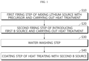
- FIG. 1 is a flow chart illustrating the method for preparing a positive electrode active material according to the present disclosure.
- the method for preparing a positive electrode active material according to the present disclosure will be explained in more detail with reference to FIG. 1 .
- step S10 the first firing step of mixing a lithium source with a precursor and carrying out heat treatment is carried out.
- a positive electrode active material for a lithium secondary battery is prepared through the first firing step (S10).
- a NCM-based lithium transition metal composite oxide may be prepared.
- the positive electrode active material prepared according to the present disclosure is a NCM-based lithium transition metal composite oxide, but a different type of positive electrode active material used for a lithium secondary battery may also be prepared according to the present disclosure.
- the precursor is a starting material, and may be prepared by mixing and reacting an aqueous solution of nickel compound, cobalt compound, manganese compound, or the like, with an alkaline solution to obtain a precipitate as a reaction product, and drying and heat treating the precipitate.
- the precursor may be represented by the following Chemical Formula 1: [Chemical Formula 1] Ni x1 Co y1 Mn z1 Al s1 (OH) 2 wherein 0.7 ⁇ x1 ⁇ 0.99, 0 ⁇ y1 ⁇ 0.3, 0 ⁇ z1 ⁇ 0.3, and 0 ⁇ s1 ⁇ 0.1.
- the precursor may be one from which a Ni-rich lithium transition metal oxide is prepared, wherein the precursor may have a nickel content of 70 mol% or more based on the total mole number of transition metals.
- the lithium source may be a lithium compound, such as Li 2 CO 3 or LiOH ⁇ H 2 O.
- the fired product obtained through the first firing step (S10) may be a lithium transition metal composite oxide represented by the following Chemical Formula 2: [Chemical Formula 2] Li a [Ni b Co c Mn d Al e ] 1-f M 1 f O 2 wherein M 1 represents at least one selected from the group consisting of Zr, W, Mg, Ce, Hf, Ta, La, Ti, Sr, Ba, F, P and S, 0.8 ⁇ a 1.2, 0.7 ⁇ b ⁇ 0.99, 0 ⁇ c ⁇ 0.3, 0 ⁇ d ⁇ 0.3, 0.01 ⁇ e ⁇ 0.1, and 0 ⁇ f ⁇ 0.1.
- the lithium transition metal composite oxide may be LiNi 0.86 Co 0.05 Mn 0.07 Al 0.02 O 2 .
- the heat treatment in the first firing step may be carried out at an oxygen concentration of 21-100%.
- the heat treatment temperature of the first firing step may be set to 0.75-1.5 times of the heat treatment temperature of the second firing step carried out after the first firing step.
- the heat treatment temperature may be varied suitably within the above-defined range depending on the content of each element in NCM.
- the heat treatment in the first firing step may be carried out at 500-900°C. When the temperature is lower than 500°C, the reaction may not occur sufficiently. When the temperature is higher than 900°C, the positive electrode material may be thermally decomposed to cause degradation of performance.
- the second firing step of mixing the fired product obtained from the first firing step with the first B source and carrying out heat treatment to form a surface protective layer on the fired product is carried out (step S20).
- the heat treatment in the second firing step may be carried out by cooling the fired product after the heat treatment of the first firing step (step S10) and introducing the first B source to the fired product.
- the method according to an embodiment of the present disclosure is characterized in that no B source is mixed in the first firing step (step S10), and then the B source is introduced subsequently twice in division.
- the first introduction time point is the second firing step (step S20).
- the B source introduced in the second firing step is referred to as the first B source.
- the first B source is a coating/doping material, and may be any one selected from H 3 BO 3 , H 4 BO 4 , B 2 O 3 , LiBO 2 , Li 2 B 4 O 7 , B 4 C, AlBOz and AlB 2 O 4 , or a combination thereof.
- the method for mixing the fired product obtained from the first firing step with the first B source may be carried out by a solid phase process or a liquid phase process.
- a solid phase or liquid phase process may include mixing, milling, spray drying, grinding, or the like.
- a dry solid phase process is used.
- the heat treatment in the second firing step may be carried out at an oxygen concentration of 21-100%. Similarly to the heat treatment in the first firing step, the heat treatment in the second firing step may be carried out at 500-900°C. When the heat treatment temperature is lower than 500°C, it is not possible to form a surface protective layer smoothly or homogeneously. When the heat treatment temperature is higher than 900°C, the positive electrode active material may not retain its original properties.
- the heat treatment temperature may be varied suitably within the above-defined range depending on the content of each element in NCM. However, as mentioned above, the heat treatment temperature in the first firing step is preferably 0.75-1.5 times of the heat treatment temperature of the second firing step.
- the method according to an embodiment of the present disclosure is characterized in that firing is not carried out at once but is carried out twice (the first firing step and the second firing step) in division.
- the B source is not added in the first firing step but is added in the second firing step.
- the B source as a coating/doping material is not introduced in the first firing step, but is introduced merely in the second firing step.
- the first B source introduced in the second firing step allows the fired product to be coated/doped with B element to form a surface protective layer.
- One part of the first B source is incorporated into the fired product to perform doping, while the other part of the first B source is disposed on the surface of the fired product to form a B source coating layer, which functions as the surface protective layer.
- the B source is introduced merely in the final step after the completion of firing to carry out coating.
- the B source is added in the second firing step at a time point different from the introduction time of the lithium source. In this manner, it is possible to obtain an effect of improving the reactivity of the B source with the positive electrode active material.
- the surface protective layer formed in the second firing step inhibits surface deterioration of the positive electrode active material in the subsequent water-washing step (S30). Therefore, it is to be noted that the surface protective layer is already formed on the surface of the fired product before carrying out the water-washing step (S30) according to the method of the present disclosure, thereby inhibiting surface deterioration of the positive electrode active material surface in the water-washing step (S30).
- the fired product obtained through the second firing step (S20) may be a lithium transition metal composite oxide represented by the following Chemical Formula 3: [Chemical Formula 3] Li a [Ni b Co c Mn d Al e ] 1-f (B, M 1 ) f O 2 wherein M 1 represents at least one selected from the group consisting of Zr, W, Mg, Ce, Hf, Ta, La, Ti, Sr, Ba, F, P and S, 0.8 ⁇ a 1.2, 0.7 ⁇ b ⁇ 0.99, 0 ⁇ c ⁇ 0.3, 0 ⁇ d ⁇ 0.3, 0.01 ⁇ e ⁇ 0.1, and 0 ⁇ f ⁇ 0.1.
- Chemical Formula 3 Li a [Ni b Co c Mn d Al e ] 1-f (B, M 1 ) f O 2
- M 1 represents at least one selected from the group consisting of Zr, W, Mg, Ce, Hf, Ta, La, Ti, Sr
- step S30 a water-washing step of removing unreacted lithium remaining on the surface of the fired product obtained from the second firing step is carried out.
- the positive electrode active material may include a lithium compound, such as LiOH, remaining thereon, such a water-washing step may be required.
- the water-washing step may be carried out by mixing the fired product with water at a weight ratio of 50-200% and carrying out agitation. During the washing, additives, such as LiOH and NaOH, may be introduced.
- the surface protective layer is formed on the fired product of positive electrode active material by using a process of B element coating/doping in the second firing step, the B element coating layer formed during the firing may have an effect of inhibiting surface deterioration of the positive electrode active material that may occur in the water-washing step.
- the method according to an embodiment of the present disclosure provides a significant effect of inhibiting surface deterioration of the positive electrode active material in the water-washing step.
- the surface of the fired product subjected to water-washing includes no surface protective layer as disclosed herein.
- step S40 a coating step of drying the washed product obtained from the water-washing step and carrying out heat treatment together with the second B source is carried out.
- the B source is not mixed in the first firing step (step S10), but is added subsequently twice in division.
- the first introduction time point is the above-described second firing step (step S20), and the second introduction time point is the coating step (step S40).
- the B source introduced in the coating step is referred to as the second B source.
- the second B source is a coating/doping material, and may be any one selected from H 3 BO 3 , H 4 BO 4 , B 2 O 3 , LiBO 2 , Li 2 B 4 O 7 , B 4 C, AlBOz and AlB 2 O 4 , or a combination thereof.
- the method for mixing the water-washed and dried product with the second B source may be carried out by a solid phase process or a liquid phase process. Such a solid phase or liquid phase process may include mixing, milling, spray drying, grinding, or the like.
- the heat treatment in the second firing step may be carried out at an oxygen concentration of 21-100%.
- the heat treatment in step S40 may be carried out at 200-400°C.
- the heat treatment temperature in step S40 is preferably lower than 400°C.
- the first source may be the same as or different from the second source.
- the content of the first B source and the second B source are in such levels that the weight ratio of B/positive electrode active material equals to 200-5,000 ppm.
- the weight ratio of B/positive electrode active material When the weight ratio of B/positive electrode active material is smaller than 200 ppm, there is no effect of coating. When the weight ratio of B/positive electrode active material is larger than 5,000 ppm, an excessive amount of coating layer may be formed, which is not preferred in terms of capacity and resistance.
- the washed and dried product is heat treated together with the second B source at low temperature, the reactivity of the positive electrode active material surface with B is varied, thereby improving the high-temperature life, resistance increase and low-temperature output characteristics.
- the reactivity of the second B source introduced in the coating step (S40) with the positive electrode active material surface is higher than the reactivity of the B source with the deteriorated positive electrode active material surface having no surface protective layer and subjected to water-washing.
- the positive electrode active material that may be prepared by the above-described method according to the present disclosure has the following characteristics.
- the positive electrode active material according to the present disclosure includes a lithium boron compound coating layer on the surface of a powder of a positive electrode active material for a lithium secondary battery, wherein the coating layer shows a peak intensity ratio of two optional peaks in the spectrum of Time-of-Flight Secondary Ion Mass Spectrometry (ToF-SIMS), equal to the peak intensity ratio of the corresponding peaks of LiBO 2 compound within a range of ⁇ 50%.
- TOF-SIMS Time-of-Flight Secondary Ion Mass Spectrometry
- the positive electrode active material according to the present disclosure may include a lithium boron compound coating layer on the surface of a powder of a positive electrode active material for a lithium secondary battery, wherein the coating layer may show a peak intensity ratio of two optional peaks in the spectrum of Time-of-Flight Secondary Ion Mass Spectrometry (ToF-SIMS), equal to the peak intensity ratio of the corresponding peaks of LiBOz compound within a range of ⁇ 50%.
- TOF-SIMS Time-of-Flight Secondary Ion Mass Spectrometry
- the positive electrode active material may be a NCM-based lithium transition metal composite oxide.
- the reactivity with an electrolyte should be reduced in order to increase the stability under cycle operation environment.
- the positive electrode active material including the coating layer according to the present disclosure can reduce the reactivity with an electrolyte, and thus can reduce gas generation at high temperature.
- the positive electrode active material including the coating layer according to the present disclosure provides improved high-temperature life, resistance increase and output characteristics.
- the coating layer may show a peak intensity ratio of the peak having the highest intensity among the peaks detected at a mass of 156.85-156.95 to the peak having the highest intensity among the peaks detected at a mass of 153.05-153.15 of 4.3 ⁇ 50%, in the ToF-SIMS spectrum.
- the expression '4.3 ⁇ 50%' refers to a range of 4.3-2.15 (50% of 4.3) to 4.3+2.15, i.e. 2.15 to 6.45.
- the coating layer may show a peak intensity ratio of the peak having the highest intensity among the peaks detected at a mass of 182.85-182.95 to the peak having the highest intensity among the peaks detected at a mass of 179.05-179.15 of 9.9 ⁇ 50%, in the ToF-SIMS spectrum.
- the expression '9.9+50%' refers to a range of 9.9-4.95 (50% of 9.9) to 9.9+4.95, i.e. 4.95 to 14.85.
- the coating layer of the positive electrode active material according to the present disclosure shows peaks present in a specific mass range as determined by ToF-SIMS, wherein the peaks have a predetermined peak intensity ratio, and the peak intensity ratio is equal to the peak intensity ratio of the corresponding peaks in LiBO 2 compound within a range of ⁇ 50%.
- the positive electrode active material is used for a positive electrode for a lithium secondary battery, it is possible to provide high output and high stability.
- LiOH ⁇ H 2 O used as a lithium source and Ni 0.88 Co 0.05 Mn 0.07 (OH) 2 + A1(OH) 3 used as a precursor were used and mixed in such a manner that the molar ratio of Li : transition metals (Ni, Co, Mn, Al) may be 1.03 : 1, and the resultant mixture was subjected to the first firing step at 700°C for 5 hours to obtain LiNi 0.86 Co 0.05 Mn 0.07 Al 0.02 O 2 as the first fired product.
- the first fired product was mixed with the first B source, H 3 BO 3 , at a weight ratio of 100 : 0.86, and the resultant mixture was subjected to the second firing step at 750°C for 5 hours.
- the fired product was mixed with water at a weight ratio of 100 : 100, and agitation was carried out for 5 minutes. Then, the washed product was filtered by using a filter press and vacuum dried at 130°C. After that, the dried product was mixed with the second B source, H 3 BO 3 , at a weight ratio of 100 : 0.57, and the resultant mixture was heat treated at 300°C for 4 hours to obtain a positive electrode active material surface-coated with B.
- LiOH HxO used as a lithium source was mixed with Ni 0.88 Co 0.05 Mn 0.07 (OH) 2 + Al(OH) 3 used as a precursor in such a manner that the molar ratio of Li : transition metals (Ni, Co, Mn, Al) may be 1.03 : 1, and the resultant mixture was subjected to the first firing step at 700°C for 5 hours to obtain the first fired product of LiNi 0.86 Co 0.05 Mn 0.07 Al 0.02 O 2 . Next, no B source was added thereto, and the second firing step was carried out at 750°C for 5 hours.
- LiOH ⁇ H 2 O used as a lithium source was mixed with Ni 0.88 Co 0.05 Mn 0.07 (OH) 2 + Al(OH) 3 used as a precursor in such a manner that the molar ratio of Li : transition metals (Ni, Co, Mn, Al) may be 1.03:1, and the resultant mixture was subjected to the first firing step at 700°C for 5 hours to obtain the first fired product of LiNi 0.86 Co 0.05 Mn 0.07 Al 0.02 O 2 .
- no B source was added thereto, and the second firing step was carried out at 750°C for 5 hours.
- the fired product was mixed with water at a weight ratio of 100:100, and the resultant mixture was agitated for 5 minutes.
- the washed product was filtered through a filter press, and vacuum drying was carried out at 130°C. After that, the dried product was mixed with H 3 BO 3 at a weight ratio of 100:0.57, and heat treatment was carried out at 300°C for 4 hours.
- LiOH ⁇ H 2 O used as a lithium source was mixed with Ni 0.88 Co 0.05 Mn 0.07 (OH) 2 + Al(OH) 3 used as a precursor in such a manner that the molar ratio of Li : transition metals (Ni, Co, Mn, Al) may be 1.03 : 1, the resultant mixture was mixed with H 3 BO 3 so that Ni 0.88 Co 0.05 Mn 0.07 (OH) 2 and H 3 BO 3 are mixed at a weight ratio of 100 : 0.91, and then the first firing step was carried out at 700°C for 5 hours, and the second firing step was carried out at 750°C for 5 hours.
- LiOH ⁇ H 2 O used as a lithium source was mixed with Ni 0.88 Co 0.05 Mn 0.07 (OH) 2 + Al(OH) 3 used as a precursor in such a manner that the molar ratio of Li : transition metals (Ni, Co, Mn, Al) may be 1.03 : 1, the resultant mixture was mixed with H 3 BO 3 so that Ni 0.88 Co 0.05 Mn 0.07 (OH) 2 and H 3 BO 3 are mixed at a weight ratio of 100 : 0.91, and then the first firing step was carried out at 700°C for 5 hours, and the second firing step was carried out at 750°C for 5 hours. The fired product was mixed with water at a weight ratio of 100 : 100, and the resultant mixture was agitated for 5 minutes.
- the washed product was filtered through a filter press, and vacuum drying was carried out at 130°C. After that, the dried product was mixed with H 3 BO 3 at a weight ratio of 100 : 0.57, and heat treatment was carried out at 300°C for 4 hours.
- LiOH ⁇ H 2 O used as a lithium source was mixed with Ni 0.88 Co 0.05 Mn 0.07 (OH) 2 + Al(OH) 3 used as a precursor in such a manner that the molar ratio of Li : transition metals (Ni, Co, Mn, Al) may be 1.03 : 1, and the resultant mixture was subjected to the first firing step at 700°C for 5 hours to obtain the first fired product of LiNi 0.86 Co 0.05 Mn 0.07 Al 0.02 O 2 . Then, the first fired product was mixed with H 3 BO 3 at a weight ratio of 100 : 0.86, and the second firing step was carried out at 750°C for 5 hours.
- the test items include a time change test, an electrochemical data of a coin half-cell, a low-temperature output data of a mono-cell, a high-temperature life data of a mono-cell, and determination of peaks detected upon the B source addition through Time-of-Flight Secondary Ion Mass Spectrometry (ToF-SIMS).
- TOF-SIMS Time-of-Flight Secondary Ion Mass Spectrometry
- ToF-SIMS was carried out to identify the ingredients of the coating layer.
- X-ray diffractometry XRD
- the coating layer of the positive electrode active material has a thickness of several nanometers to several tens of nanometers, it is difficult to detect peaks by XRD.
- a significantly thin coating layer were analyzed in terms of its ingredients through ToF-SIMS. After carrying out ToF-SIMS, it was shown that a lithium boron compound coating layer was formed additionally on the positive electrode active material surface. In other words, it was shown that a lithium boron compound was formed additionally by the method according to the present disclosure.
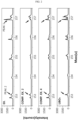
- FIGS. 2 and 3 show the results of ToF-SIMS of Comparative Examples 2 and 4 and Example. For the purpose of comparison, the result of LiBOz is also shown.
- the peak (peak 1) having the highest intensity among the peaks detected at a mass of 156.85-156.95 is the peak detected at a mass of 156.9.
- the peak (peak 2) having the highest intensity among the peaks detected at a mass of 153.05-153.15 is the peak detected at a mass of 153.1.
- the mass values are those measured by calibration of the ToF-SIMS spectrum with Li + , C + , C2 + and C3 + peaks.
- the ratio of peak 1 to peak 2 is 4.3.
- the ratio of the peak having highest intensity among the peaks detected at a mass of 156.85-156.95 to the peak having the highest intensity among the peaks detected at a mass of 153.05-153.15 may be 4.3 ⁇ 50%.
- the peak intensity ratio of the peak detected at a mass of 156.9 to the peak detected at a mass of 153.1 is similar to the peak intensity ratio of the corresponding peak intensity (i.e. peak intensity ratio of peak 1 to peak 2 in LiBO 2 compound) of LiBOz compound within a range of ⁇ 50%.
- the term 'similar' means that the ratio of Example is the same as the ratio of LiBOz within a range of ⁇ 50%.
- Comparative Examples 2 and 4 those peaks are observed in a different pattern.
- the ratio of peak 1 to peak 2 is 0.3 and 2.0, respectively.
- the peak (peak 3) having the highest intensity among the peaks detected at a mass of 182.85-182.95 is the peak detected at a mass of 182.9.
- the peak (peak 4) having the highest intensity among the peaks detected at a mass of 179.05-179.15 is the peak detected at a mass of 179.1.
- the mass values are those measured by calibration of the ToF-SIMS spectrum with Li + , C + , C2 + and C3 + peaks.
- the ratio of peak 3 to peak 4 is 9.9.
- the ratio of the peak having highest intensity among the peaks detected at a mass of 182.85-182.95 to the peak having the highest intensity among the peaks detected at a mass of 179.05-179.15 may be 9.9 ⁇ 50%.
- the peak intensity ratio of the peak detected at a mass of 182.9 to the peak detected at a mass of 179.1 is similar to the peak intensity ratio of the corresponding peak intensity (i.e. peak intensity ratio of peak 3 to peak 4 in LiBO 2 compound) of LiBOz compound within a range of ⁇ 50%.
- the term 'similar' means that the ratio of Example is the same as the ratio of LiBOz within a range of ⁇ 50%.
- Comparative Examples 2 and 4 those peaks are observed in a different pattern.
- the ratio of peak 3 to peak 4 is 1.5 and 3.0, respectively.
- the lithium boron compound having the above-mentioned peak intensity ratio characteristics is incorporated to the coating layer, high-temperature life characteristics and low-temperature output characteristics are improved.
- Each of the positive electrode active materials according to Example and Comparative Examples 1-5, carbon black as a conductive material and PVDF as a binder were mixed in N-methyl pyrrolidone as a solvent at a weight ratio of 96 : 2 : 2 to prepare a positive electrode slurry.
- the positive electrode slurry was applied onto one surface of an aluminum current collector, dried at 130°C and pressed to obtain a positive electrode.
- Lithium metal was used as a negative electrode.
- a porous polyethylene separator was interposed between the positive electrode and the negative electrode to provide an electrode assembly, which, in turn, was received in a casing, and an electrolyte was injected into the casing to obtain a lithium secondary battery.
- the electrolyte was prepared by dissolving 1.0 M of lithium hexafluorophosphate (LiPF 6 ) in an organic solvent including ethylene carbonate/ethyl methyl carbonate/diethyl carbonate (EC/MC/DEC) mixed at a volume ratio of 3/4/3.
- LiPF 6 lithium hexafluorophosphate
- organic solvent including ethylene carbonate/ethyl methyl carbonate/diethyl carbonate (EC/MC/DEC) mixed at a volume ratio of 3/4/3.
- Each of the lithium secondary battery half-cell was charged at 0.1 C to 4.25 V at 25°C in a constant current-constant voltage (CC-CV) mode, and discharged at a constant current of 0.1 C to 3.0 V to carry out a charge/discharge test.
- CC-CV constant current-constant voltage
- DCIR direct current internal resistance
- Each a positive electrode active material, a conductive material, a binder and an additive were mixed at a ratio of 97.5/1.0/1.35/0.15 to prepare a positive electrode slurry.
- the positive electrode slurry was coated on an aluminum current collector, and natural graphite was mixed with artificial graphite at a specific ratio to prepare a negative counter electrode.
- An electrolyte was prepared at a salt concentration of 0.7 M, and lithium bis(fluorosulfonyl)imide (LiFSI, 0.3 M) was added thereto in order to maintain the life.
- the electrolyte was injected in an amount of 100 ⁇ L, and a separator manufactured by our own company and prepared with an adequate size was interposed between the positive electrode and the negative electrode.
- the electrolyte was injected to the prepared mono-cell, charge/discharge cycles were carried out, and the initial gases were removed to prepare evaluation of the mono-cell.
- the charge/discharge cycles were carried out at a temperature of 25°C.
- the mono-cell was determined in terms of a drop in voltage ( ⁇ voltage) and resistance, while being discharged at -10°C and at 2.0 C from SOC 10 to 0.
- each mono-cell was charged at 45°C in a constant current mode at 0.5 C to 4.2 V, discharged at a constant current of 1.0 C to 3.0 V, charged at a constant current of 0.33 C to 4.2 V at 25°C when each of the 100 th , 200 th , 300 th and 400 th cycles reached, and discharged at a constant current of 0.33 C to 3.0 V to carry out a charge/discharge test, and the capacity retention and an increase in resistance were measured.
- the fired product of each positive electrode active material was determined in terms of improvement of a change with time.
- the change with time was evaluated as a change in Li 2 CO 3 weight remaining on the surface.
- Table 1 shows the results of the time change test of Comparative Examples 1 and 5, wherein the weight ratio of Li 2 CO 3 /fired product was measured on the first day (0 day), after 1 day (1 day), after 2 days (2 day) and after 3 days (3 day).
- [Table 1] Time change Weight ratio of Li 2 CO 3 /fired product 0 day 1 day 2 day 3 day Comp. Ex. 1 0.633 0.864 1.012 1.081 Comp. Ex. 5 0.445 0.602 0.679 0.696
- Comparative 5 shows a smaller change with time as compared to Comparative Example 1. Therefore, it can be seen that Comparative Example 5 in which the second firing step is carried out with the B source added thereto provides a better result in terms of a change with time, as compared to Comparative Example 1 with no B source added thereto. According to the present disclosure, the second firing step is carried out with the B source added, and thus it is possible to accomplish improvement in terms of a change with time.
- Table 2 shows the electrochemical data including the charge capacity, discharge capacity, efficiency and DCIR of each coin half-cell.
- Electrochemical data of coin half-cell 25°C 0.1 C/0.1 C Charge capacity Discharge capacity Efficiency DCIR Example 231.5 212.3 91.7 19.3 Comp. Ex. 2 230.0 207.9 90.4 19.7 Comp. Ex. 4 230.4 207.8 90.2 20.8
- Example according to the present disclosure shows a higher charge capacity, discharge capacity and efficiency, and a lower DCIR, as compared to Comparative Example 2 or 4.
- Comparative Example 2 includes two-step firing, but no B source is mixed in the second firing step, unlike the present disclosure. Comparative Example 2 includes mixing the B source in the first firing step, not in the second firing step, unlike the present disclosure. Therefore, when the B source is not mixed in the first firing step but mixed in the second firing step according to the present disclosure, it is possible to improve the charge capacity, discharge capacity, efficiency and DCIR. As a result, it can be seen that it is possible to reduce the surface resistance of the positive electrode active material in the positive electrode of a lithium secondary battery by using the method according to the present disclosure. Particularly, in the case of Comparative Example 4 wherein the B source is introduced in the firing step, it can be seen that the positive electrode active material cannot realize its capacity but causes an increase in DCIR undesirably.
- Table 3 shows the low-temperature output data of a mono-cell.
- Table 3 Low-temperature output data of mono-cell Discharge at -10°C/2.0 C 0-10 sec 0-1350 sec ⁇ Voltage Resistance ( ⁇ ) Percentage ⁇ of resistance (%) ⁇ Voltage Resistance ( ⁇ ) Percentage ⁇ of resistance (%) Example 0.212 27.107 -11 0.263 33.58 -10.5 Comp. Ex. 2 0.242 30.463 0 0.298 37.52 0
- Example according to the present disclosure shows improved output characteristics, including a drop in voltage ( ⁇ voltage) and resistance, as compared to Comparative Example 2.
- Comparative Example 2 includes two-step firing, but the B source is not mixed in the second firing step, unlike the present disclosure. Therefore, when the B source is not mixed in the first firing step but mixed in the second according to the present disclosure, it is possible to improve the low-temperature output characteristics.
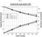
- Table 4 shows data of high-temperature life of a mono-cell, including capacity retention and an increase in resistance, as determined every 100 th cycle, and FIG. 4 is a graph illustrating the capacity retention and an increase in resistance as a function of cycle number.
- Table 4 High-temperature life data of mono-cell 25°C 0.33 C/0.33 C 100 th cycle 200 th cycle 300 th cycle 400 th cycle Capacity retention Increase in resistance Capacity retention Increase in resistance Capacity retention Increase in resistance Capacity retention Increase in resistance Capacity retention Increase in resistance Example 96.35 14.81 93.07 31.83 90.74 40.99 89.20 53.11 Comp. Ex. 2 95.82 18.52 92.16 37.09 89.62 45.70 87.81 56.31 Comp. Ex. 4 96.57 14.14 92.66 33.15 89.69 45.92 87.11 60.30
- Example according to the present disclosure shows a higher capacity retention and a smaller increase in resistance, as compared to Comparative Example 2 or 4.
- the coated positive electrode active material provides improved characteristics by carrying out the firing process in two steps and introducing the B source and lithium source at a different time point to improve the reactivity of the B source with the positive electrode active material.
Landscapes
- Chemical & Material Sciences (AREA)
- Chemical Kinetics & Catalysis (AREA)
- Electrochemistry (AREA)
- General Chemical & Material Sciences (AREA)
- Inorganic Chemistry (AREA)
- Organic Chemistry (AREA)
- Engineering & Computer Science (AREA)
- Composite Materials (AREA)
- Manufacturing & Machinery (AREA)
- Materials Engineering (AREA)
- Crystallography & Structural Chemistry (AREA)
- Battery Electrode And Active Subsutance (AREA)
Abstract
Description
- The present disclosure relates to a positive electrode active material for a lithium secondary battery and a method for preparing the same. The present application claims priority to
Korean Patent Application No. 10-2021-0107659 filed on August 13, 2021 - Rechargeable lithium secondary batteries have been spotlighted as substitutes for fossil energy. Lithium secondary batteries have been used frequently for conventional hand-held devices, such as cellular phones, video cameras and power tools. However, recently, application of such lithium secondary batteries tends to be extended gradually to electrically driven vehicles (EV, HEV, PHEV), large-capacity energy storage systems (ESS), uninterruptible power supply systems (UPS), or the like.
- A lithium secondary battery has a structure including an electrode assembly of unit cells having a positive electrode plate and a negative electrode plate, each of which includes an active material coated on an electrode current collector, and a separator interposed between both electrodes; and an exterior material, i.e. a battery casing configured to receive and seal the electrode assembly together with an electrolyte. As a positive electrode material for such a lithium secondary battery, a lithium transition metal composite oxide has been used. Particularly, lithium cobalt oxide (LiCoO2), lithium manganese oxide (LiMnOz or LiMn2O4), lithium iron phosphate (LiFePO4) or LiNiOz has been used frequently. In addition, in order to improve low heat stability of LiNiOz, while maintaining its excellent reversible capacity, there has been used nickel manganese-based lithium metal composite oxide in which nickel is partially substituted with manganese having high thermal stability, NCM-based lithium transition metal composite oxide in which nickel is partially substituted with manganese and cobalt, NCA-based lithium transition metal composite oxide in which nickel is partially substituted with cobalt and aluminum, or NCMA-based lithium transition metal composite oxide in which nickel is partially substituted with cobalt, manganese and aluminum.
- Among such positive electrode active materials, the Ni-based lithium positive electrode material using Ni has been prepared by mixing a lithium source with a precursor, firing the resultant mixture at high temperature, and further firing the resultant product together with H3BO3 at low temperature so that the surface may be coated with B. However, the above-mentioned method is problematic in that it has a limitation in improvement of the high-temperature life characteristics and resistance increase of a positive electrode active material, and thus there is a need for improvement of the problem.
- The present disclosure is designed to solve the problems of the related art, and therefore the present disclosure is directed to providing a positive electrode active material for a lithium secondary battery, improved in terms of high-temperature life characteristics and resistance increase, and a method for preparing the same.
- To solve the above technical problem, in one aspect of the present disclosure, there is provided a positive electrode active material for a lithium secondary battery, including a lithium boron compound coating layer on the surface of a powder of a positive electrode active material for a lithium secondary battery, wherein the coating layer shows a peak intensity ratio of two optional peaks in the spectrum of Time-of-Flight Secondary Ion Mass Spectrometry (ToF-SIMS), equal to the peak intensity ratio of the corresponding peaks of LiBO2 compound within a range of ±50%.
- Herein, the coating layer may show a peak intensity ratio of the peak having the highest intensity among the peaks detected at a mass of 156.85-156.95 to the peak having the highest intensity among the peaks detected at a mass of 153.05-153.15 of 4.3±50%, in the ToF-SIMS spectrum.
- In addition, the coating layer may show a peak intensity ratio of the peak having the highest intensity among the peaks detected at a mass of 182.85-182.95 to the peak having the highest intensity among the peaks detected at a mass of 179.05-179.15 of 9.9±50%, in the ToF-SIMS spectrum.
- In another aspect of the present disclosure, there is provided a method for preparing a positive electrode active material for a lithium secondary battery, including: a first firing step of mixing a lithium source with a precursor and heat treating the resultant mixture; a second firing step of mixing the fired product obtained from the first firing step with a first B source and heat treating the resultant mixture to form a surface protective layer on the fired product; a water-washing step of removing unreacted lithium remaining on the surface of the fired product obtained from the second firing step; and a coating step of drying the product washed with water in the preceding step and heat treating the resultant product together with a second B source.
- The precursor may be a Ni-rich lithium transition metal oxide, which may have a nickel content of 70 mol% or more based on the total mole number of transition metals.
- The heat treatment temperature in the first firing step may be 0.75-1.5 times of the heat treatment temperature in the second firing step.
- The water-washing step may be carried out by mixing the fired product with water at a weight ratio of 50-200% and carrying out agitation.
- The first B source or the second B source may be any one selected from H3BO3, H4BO4, B2O3, LiBO2, Li2B4O7, B4C, AlBO2 and AlB2O4, or a combination thereof.
- The content of the first B source and the second B source are in such levels that the weight ratio of B/positive electrode active material equals to 200-5,000 ppm.
- According to the present disclosure, there is provided a positive electrode active material for a lithium secondary battery, improved in terms of high-temperature life characteristics, resistance increase and output characteristics.
- According to the method of the present disclosure, it is possible to obtain a positive electrode active material for a lithium secondary battery, improved in terms of high-temperature life characteristics and resistance increase by controlling the B coating/doping time point during the firing step.
- In the method according to the present disclosure, the B source is added in the second firing step at a different time point from the addition of the lithium source, thereby providing an effect of improving the reactivity of the B source with the positive electrode active material.
- According to the method of the present disclosure, the second firing step includes a process of B element coating/doping to form a surface protective layer on the fired product of positive electrode active material. Therefore, the B element coating layer formed during the firing can effectively inhibit surface deterioration of the positive electrode active material that may occur during the water-washing step.
- According to the method of the present disclosure, the reactivity of the positive electrode active material surface with B is varied, when heat treating the dried water-washed product together with the second B source at low temperature, thereby providing the positive electrode active material with improved high-temperature life characteristics, resistance increase and low-temperature output characteristics.
- The accompanying drawings illustrate a preferred embodiment of the present disclosure and together with the foregoing disclosure, serve to provide further understanding of the technical features of the present disclosure, and thus, the present disclosure is not construed as being limited to the drawing.
-
FIG. 1 is a flow chart illustrating the method for preparing a positive electrode active material according to the present disclosure. -
FIGS. 2 and3 show the results of Time-of-Flight Secondary Ion Mass Spectrometry (ToF-SIMS) of Example and Comparative Examples 2 and 4. -
FIG. 4 is a graph illustrating the capacity retention and resistance increase as a function of cycle number. - Hereinafter, preferred embodiments of the present disclosure will be described in detail with reference to the accompanying drawings. Prior to the description, it should be understood that the terms used in the specification and the appended claims should not be construed as limited to general and dictionary meanings, but interpreted based on the meanings and concepts corresponding to technical aspects of the present disclosure on the basis of the principle that the inventor is allowed to define terms appropriately for the best explanation. Therefore, the description proposed herein is just a preferable example for the purpose of illustrations only, not intended to limit the scope of the disclosure, so it should be understood that other equivalents and modifications could be made thereto without departing from the scope of the disclosure.
- In the following description, reference will be made to the accompanying drawings forming a part of the present disclosure. The embodiments described in the detailed description, drawing and claims are not intended to be limiting of the present disclosure. Other embodiments and modifications may be made without departing from the scope of the present disclosure. The embodiments described generally herein and depicted in the drawings may be arranged, substituted, combined, separated and designed with various different constitutional elements. It will be understood that all of them are clearly considered herein.
- Unless otherwise stated, all of the technological and scientific terms used herein have the same meanings as understood commonly by those skilled in the art to which the present disclosure belongs.
- While the present disclosure will be described with respect to the specific embodiments, it will be apparent to those skilled in the art that various changes and modifications may be made without departing from the scope of the present disclosure. In addition to the above, it should be understood that other equivalents could be made without departing from the scope of the disclosure. Such modifications and changes also fall within the scope of the following claims. The scope of the present disclosure will be defined merely by the claims together with the whole range of equivalents qualified by the claims. It should be also understood that the present disclosure is not limited to particular embodiments which are variable. Further, it should be understood that the terminology used herein is for the purpose of describing particular embodiments only and is not intended to be limiting of the present disclosure.
-
FIG. 1 is a flow chart illustrating the method for preparing a positive electrode active material according to the present disclosure. Hereinafter, the method for preparing a positive electrode active material according to the present disclosure will be explained in more detail with reference toFIG. 1 . - First, the first firing step of mixing a lithium source with a precursor and carrying out heat treatment is carried out (step S10).
- A positive electrode active material for a lithium secondary battery is prepared through the first firing step (S10). For example, a NCM-based lithium transition metal composite oxide may be prepared. Preferably, the positive electrode active material prepared according to the present disclosure is a NCM-based lithium transition metal composite oxide, but a different type of positive electrode active material used for a lithium secondary battery may also be prepared according to the present disclosure.
- The precursor is a starting material, and may be prepared by mixing and reacting an aqueous solution of nickel compound, cobalt compound, manganese compound, or the like, with an alkaline solution to obtain a precipitate as a reaction product, and drying and heat treating the precipitate. For example, the precursor may be represented by the following Chemical Formula 1:
[Chemical Formula 1] Nix1Coy1Mnz1Als1(OH)2
wherein 0.7 ≤ x1 ≤ 0.99, 0 < y1 < 0.3, 0 < z1 < 0.3, and 0 ≤ s1 ≤ 0.1. - For example, the precursor may be one from which a Ni-rich lithium transition metal oxide is prepared, wherein the precursor may have a nickel content of 70 mol% or more based on the total mole number of transition metals.
- The lithium source may be a lithium compound, such as Li2CO3 or LiOH·H2O.
- The fired product obtained through the first firing step (S10) may be a lithium transition metal composite oxide represented by the following Chemical Formula 2:
[Chemical Formula 2] Lia[NibCocMndAle]1-fM1 fO2
wherein M1 represents at least one selected from the group consisting of Zr, W, Mg, Ce, Hf, Ta, La, Ti, Sr, Ba, F, P and S, 0.8 ≤ a ≤ 1.2, 0.7 ≤ b ≤ 0.99, 0 < c < 0.3, 0 < d < 0.3, 0.01 ≤ e ≤ 0.1, and 0 ≤ f ≤ 0.1. - For example, the lithium transition metal composite oxide may be LiNi0.86Co0.05Mn0.07Al0.02O2.
- In the first firing step, no B source is mixed.
- The heat treatment in the first firing step may be carried out at an oxygen concentration of 21-100%. The heat treatment temperature of the first firing step may be set to 0.75-1.5 times of the heat treatment temperature of the second firing step carried out after the first firing step. The heat treatment temperature may be varied suitably within the above-defined range depending on the content of each element in NCM. For example, the heat treatment in the first firing step may be carried out at 500-900°C. When the temperature is lower than 500°C, the reaction may not occur sufficiently. When the temperature is higher than 900°C, the positive electrode material may be thermally decomposed to cause degradation of performance.
- Next, the second firing step of mixing the fired product obtained from the first firing step with the first B source and carrying out heat treatment to form a surface protective layer on the fired product is carried out (step S20). The heat treatment in the second firing step may be carried out by cooling the fired product after the heat treatment of the first firing step (step S10) and introducing the first B source to the fired product.
- The method according to an embodiment of the present disclosure is characterized in that no B source is mixed in the first firing step (step S10), and then the B source is introduced subsequently twice in division. The first introduction time point is the second firing step (step S20). The B source introduced in the second firing step is referred to as the first B source.
- The first B source is a coating/doping material, and may be any one selected from H3BO3, H4BO4, B2O3, LiBO2, Li2B4O7, B4C, AlBOz and AlB2O4, or a combination thereof. The method for mixing the fired product obtained from the first firing step with the first B source may be carried out by a solid phase process or a liquid phase process. Such a solid phase or liquid phase process may include mixing, milling, spray drying, grinding, or the like. Preferably, a dry solid phase process is used.
- The heat treatment in the second firing step may be carried out at an oxygen concentration of 21-100%. Similarly to the heat treatment in the first firing step, the heat treatment in the second firing step may be carried out at 500-900°C. When the heat treatment temperature is lower than 500°C, it is not possible to form a surface protective layer smoothly or homogeneously. When the heat treatment temperature is higher than 900°C, the positive electrode active material may not retain its original properties. The heat treatment temperature may be varied suitably within the above-defined range depending on the content of each element in NCM. However, as mentioned above, the heat treatment temperature in the first firing step is preferably 0.75-1.5 times of the heat treatment temperature of the second firing step. It is shown that when the heat treatment temperature in the first firing step is not within the above-defined range, high-temperature life characteristics are degraded even after the first B source is added and firing, water-washing and coating are performed in the second firing step. Therefore, the condition of the relationship between the heat treatment temperature in the first firing step and the heat treatment temperature in the second firing step is critical, since it is required to prevent degradation of high-temperature life characteristics.
- In brief, the method according to an embodiment of the present disclosure is characterized in that firing is not carried out at once but is carried out twice (the first firing step and the second firing step) in division. In addition, the B source is not added in the first firing step but is added in the second firing step. The B source as a coating/doping material is not introduced in the first firing step, but is introduced merely in the second firing step. The first B source introduced in the second firing step allows the fired product to be coated/doped with B element to form a surface protective layer. One part of the first B source is incorporated into the fired product to perform doping, while the other part of the first B source is disposed on the surface of the fired product to form a B source coating layer, which functions as the surface protective layer.
- According to the related art, the B source is introduced merely in the final step after the completion of firing to carry out coating. According to the present disclosure, the B source is added in the second firing step at a time point different from the introduction time of the lithium source. In this manner, it is possible to obtain an effect of improving the reactivity of the B source with the positive electrode active material. The surface protective layer formed in the second firing step inhibits surface deterioration of the positive electrode active material in the subsequent water-washing step (S30). Therefore, it is to be noted that the surface protective layer is already formed on the surface of the fired product before carrying out the water-washing step (S30) according to the method of the present disclosure, thereby inhibiting surface deterioration of the positive electrode active material surface in the water-washing step (S30).
- The fired product obtained through the second firing step (S20) may be a lithium transition metal composite oxide represented by the following Chemical Formula 3:
[Chemical Formula 3] Lia[NibCocMndAle]1-f(B, M1)fO2
wherein M1 represents at least one selected from the group consisting of Zr, W, Mg, Ce, Hf, Ta, La, Ti, Sr, Ba, F, P and S, 0.8 ≤ a ≤ 1.2, 0.7 ≤ b ≤ 0.99, 0 < c < 0.3, 0 < d < 0.3, 0.01 ≤ e ≤ 0.1, and 0 ≤ f ≤ 0.1. - Then, a water-washing step of removing unreacted lithium remaining on the surface of the fired product obtained from the second firing step is carried out (step S30).
- Since the positive electrode active material may include a lithium compound, such as LiOH, remaining thereon, such a water-washing step may be required. The water-washing step may be carried out by mixing the fired product with water at a weight ratio of 50-200% and carrying out agitation. During the washing, additives, such as LiOH and NaOH, may be introduced.
- Since the surface protective layer is formed on the fired product of positive electrode active material by using a process of B element coating/doping in the second firing step, the B element coating layer formed during the firing may have an effect of inhibiting surface deterioration of the positive electrode active material that may occur in the water-washing step. As compared to the method of the related art in which the B source is introduced to carry out coating merely in the final step after the completion of firing, the method according to an embodiment of the present disclosure provides a significant effect of inhibiting surface deterioration of the positive electrode active material in the water-washing step. According to the related art, the surface of the fired product subjected to water-washing includes no surface protective layer as disclosed herein.
- After that, a coating step of drying the washed product obtained from the water-washing step and carrying out heat treatment together with the second B source is carried out (step S40).
- The B source is not mixed in the first firing step (step S10), but is added subsequently twice in division. The first introduction time point is the above-described second firing step (step S20), and the second introduction time point is the coating step (step S40). The B source introduced in the coating step is referred to as the second B source.
- The second B source is a coating/doping material, and may be any one selected from H3BO3, H4BO4, B2O3, LiBO2, Li2B4O7, B4C, AlBOz and AlB2O4, or a combination thereof. The method for mixing the water-washed and dried product with the second B source may be carried out by a solid phase process or a liquid phase process. Such a solid phase or liquid phase process may include mixing, milling, spray drying, grinding, or the like.
- The heat treatment in the second firing step may be carried out at an oxygen concentration of 21-100%. The heat treatment in step S40 may be carried out at 200-400°C. When the heat treatment temperature is lower than 200°C, the positive electrode active material may not realize its capacity sufficiently. When the heat treatment temperature is higher than 400°C, high-temperature life characteristics may be degraded. Therefore, the heat treatment temperature in step S40 is preferably lower than 400°C.
- The first source may be the same as or different from the second source. However, the content of the first B source and the second B source are in such levels that the weight ratio of B/positive electrode active material equals to 200-5,000 ppm.
- When the weight ratio of B/positive electrode active material is smaller than 200 ppm, there is no effect of coating. When the weight ratio of B/positive electrode active material is larger than 5,000 ppm, an excessive amount of coating layer may be formed, which is not preferred in terms of capacity and resistance. When the washed and dried product is heat treated together with the second B source at low temperature, the reactivity of the positive electrode active material surface with B is varied, thereby improving the high-temperature life, resistance increase and low-temperature output characteristics. Since deterioration of the positive electrode active material surface is inhibited by the surface protective layer in the water-washing step (step S30), the reactivity of the second B source introduced in the coating step (S40) with the positive electrode active material surface is higher than the reactivity of the B source with the deteriorated positive electrode active material surface having no surface protective layer and subjected to water-washing.
- The positive electrode active material that may be prepared by the above-described method according to the present disclosure has the following characteristics. The positive electrode active material according to the present disclosure includes a lithium boron compound coating layer on the surface of a powder of a positive electrode active material for a lithium secondary battery, wherein the coating layer shows a peak intensity ratio of two optional peaks in the spectrum of Time-of-Flight Secondary Ion Mass Spectrometry (ToF-SIMS), equal to the peak intensity ratio of the corresponding peaks of LiBO2 compound within a range of ±50%.
- The positive electrode active material according to the present disclosure may include a lithium boron compound coating layer on the surface of a powder of a positive electrode active material for a lithium secondary battery, wherein the coating layer may show a peak intensity ratio of two optional peaks in the spectrum of Time-of-Flight Secondary Ion Mass Spectrometry (ToF-SIMS), equal to the peak intensity ratio of the corresponding peaks of LiBOz compound within a range of ±50%.
- For example, the positive electrode active material may be a NCM-based lithium transition metal composite oxide. Particularly, in the case of a Ni-rich lithium transition metal composite oxide having a nickel content of 70% or more, the reactivity with an electrolyte should be reduced in order to increase the stability under cycle operation environment. The positive electrode active material including the coating layer according to the present disclosure can reduce the reactivity with an electrolyte, and thus can reduce gas generation at high temperature.
- The positive electrode active material including the coating layer according to the present disclosure provides improved high-temperature life, resistance increase and output characteristics.
- Herein, the coating layer may show a peak intensity ratio of the peak having the highest intensity among the peaks detected at a mass of 156.85-156.95 to the peak having the highest intensity among the peaks detected at a mass of 153.05-153.15 of 4.3±50%, in the ToF-SIMS spectrum. The expression '4.3±50%' refers to a range of 4.3-2.15 (50% of 4.3) to 4.3+2.15, i.e. 2.15 to 6.45.
- In addition, the coating layer may show a peak intensity ratio of the peak having the highest intensity among the peaks detected at a mass of 182.85-182.95 to the peak having the highest intensity among the peaks detected at a mass of 179.05-179.15 of 9.9±50%, in the ToF-SIMS spectrum. The expression '9.9+50%' refers to a range of 9.9-4.95 (50% of 9.9) to 9.9+4.95, i.e. 4.95 to 14.85.
- In other words, the coating layer of the positive electrode active material according to the present disclosure shows peaks present in a specific mass range as determined by ToF-SIMS, wherein the peaks have a predetermined peak intensity ratio, and the peak intensity ratio is equal to the peak intensity ratio of the corresponding peaks in LiBO2 compound within a range of ±50%. When the positive electrode active material is used for a positive electrode for a lithium secondary battery, it is possible to provide high output and high stability.
- As a result, according to the present disclosure, it is possible to improve the high-temperature life, resistance increase and low-temperature output characteristics of a positive electrode active material by controlling the time point of B coating/doping during the firing step.
- Hereinafter, the present disclosure will be explained in more detail with reference to Examples.
- First, LiOH·H2O used as a lithium source and Ni0.88Co0.05Mn0.07(OH)2 + A1(OH)3 used as a precursor were used and mixed in such a manner that the molar ratio of Li : transition metals (Ni, Co, Mn, Al) may be 1.03 : 1, and the resultant mixture was subjected to the first firing step at 700°C for 5 hours to obtain LiNi0.86Co0.05Mn0.07Al0.02O2 as the first fired product. Next, the first fired product was mixed with the first B source, H3BO3, at a weight ratio of 100 : 0.86, and the resultant mixture was subjected to the second firing step at 750°C for 5 hours. The fired product was mixed with water at a weight ratio of 100 : 100, and agitation was carried out for 5 minutes. Then, the washed product was filtered by using a filter press and vacuum dried at 130°C. After that, the dried product was mixed with the second B source, H3BO3, at a weight ratio of 100 : 0.57, and the resultant mixture was heat treated at 300°C for 4 hours to obtain a positive electrode active material surface-coated with B.
- LiOH HxO used as a lithium source was mixed with Ni0.88Co0.05Mn0.07(OH)2 + Al(OH)3 used as a precursor in such a manner that the molar ratio of Li : transition metals (Ni, Co, Mn, Al) may be 1.03 : 1, and the resultant mixture was subjected to the first firing step at 700°C for 5 hours to obtain the first fired product of LiNi0.86Co0.05Mn0.07Al0.02O2. Next, no B source was added thereto, and the second firing step was carried out at 750°C for 5 hours.
- LiOH·H2O used as a lithium source was mixed with Ni0.88Co0.05Mn0.07(OH)2 + Al(OH)3 used as a precursor in such a manner that the molar ratio of Li : transition metals (Ni, Co, Mn, Al) may be 1.03:1, and the resultant mixture was subjected to the first firing step at 700°C for 5 hours to obtain the first fired product of LiNi0.86Co0.05Mn0.07Al0.02O2. Next, no B source was added thereto, and the second firing step was carried out at 750°C for 5 hours. The fired product was mixed with water at a weight ratio of 100:100, and the resultant mixture was agitated for 5 minutes. Then, the washed product was filtered through a filter press, and vacuum drying was carried out at 130°C. After that, the dried product was mixed with H3BO3 at a weight ratio of 100:0.57, and heat treatment was carried out at 300°C for 4 hours.
- LiOH·H2O used as a lithium source was mixed with Ni0.88Co0.05Mn0.07(OH)2 + Al(OH)3 used as a precursor in such a manner that the molar ratio of Li : transition metals (Ni, Co, Mn, Al) may be 1.03 : 1, the resultant mixture was mixed with H3BO3 so that Ni0.88Co0.05Mn0.07(OH)2 and H3BO3 are mixed at a weight ratio of 100 : 0.91, and then the first firing step was carried out at 700°C for 5 hours, and the second firing step was carried out at 750°C for 5 hours.
- LiOH·H2O used as a lithium source was mixed with Ni0.88Co0.05Mn0.07(OH)2 + Al(OH)3 used as a precursor in such a manner that the molar ratio of Li : transition metals (Ni, Co, Mn, Al) may be 1.03 : 1, the resultant mixture was mixed with H3BO3 so that Ni0.88Co0.05Mn0.07(OH)2 and H3BO3 are mixed at a weight ratio of 100 : 0.91, and then the first firing step was carried out at 700°C for 5 hours, and the second firing step was carried out at 750°C for 5 hours. The fired product was mixed with water at a weight ratio of 100 : 100, and the resultant mixture was agitated for 5 minutes. Then, the washed product was filtered through a filter press, and vacuum drying was carried out at 130°C. After that, the dried product was mixed with H3BO3 at a weight ratio of 100 : 0.57, and heat treatment was carried out at 300°C for 4 hours.
- LiOH·H2O used as a lithium source was mixed with Ni0.88Co0.05Mn0.07(OH)2 + Al(OH)3 used as a precursor in such a manner that the molar ratio of Li : transition metals (Ni, Co, Mn, Al) may be 1.03 : 1, and the resultant mixture was subjected to the first firing step at 700°C for 5 hours to obtain the first fired product of LiNi0.86Co0.05Mn0.07Al0.02O2. Then, the first fired product was mixed with H3BO3 at a weight ratio of 100 : 0.86, and the second firing step was carried out at 750°C for 5 hours.
- In brief, the above Example and Comparative Examples are as follows.
- Example: Li + NCM(OH)2 + Al mixing → 700°C, the first firing step → positive electrode active material + the first B source mixing → 750°C, the second firing step → water-washing → drying, 130°C→ the second B source mixing and coating (300°C)
- Comparative Example 1 (Positive electrode active material + no B source mixing, two-step firing): Li + NCM(OH)2 + Al mixing → 700°C, the first firing step → 750°C, the second firing step
- Comparative Example 2 (Positive electrode active material + no B source mixing, two-step firing): Li + NCM(OH)2 + Al mixing → 700°C, the first firing step → 750°C, the second firing step → water-washing → drying, 130°C → H3BO3 mixing and coating (300°C)
- Comparative Example 3 (mixing lithium source with B source in the first firing step): Li + NCM(OH)2 + Al + H3BO3 mixing → 700°C, the first firing step → 750°C, the second firing step
- Comparative Example 4 (mixing lithium source with B source in the firing step): Li + NCM(OH)2 + Al + H3BO3 mixing → 700°C, the first firing step → 750°C, the second firing step → water-washing → drying, 130°C → H3BO3 mixing and coating (300°C)
- Comparative Example 5: Li + NCM(OH)2 + Al mixing → 700°C, the first firing step → positive electrode active material + H3BO3 mixing → 750°C, the second firing step
- The test items include a time change test, an electrochemical data of a coin half-cell, a low-temperature output data of a mono-cell, a high-temperature life data of a mono-cell, and determination of peaks detected upon the B source addition through Time-of-Flight Secondary Ion Mass Spectrometry (ToF-SIMS).
- ToF-SIMS was carried out to identify the ingredients of the coating layer. In general, X-ray diffractometry (XRD) is used to determine the composition and crystal structure of a material. However, since the coating layer of the positive electrode active material has a thickness of several nanometers to several tens of nanometers, it is difficult to detect peaks by XRD. According to the present disclosure, a significantly thin coating layer were analyzed in terms of its ingredients through ToF-SIMS. After carrying out ToF-SIMS, it was shown that a lithium boron compound coating layer was formed additionally on the positive electrode active material surface. In other words, it was shown that a lithium boron compound was formed additionally by the method according to the present disclosure.
-
FIGS. 2 and3 show the results of ToF-SIMS of Comparative Examples 2 and 4 and Example. For the purpose of comparison, the result of LiBOz is also shown. - Referring to
FIG. 2 , in Example, the peak (peak 1) having the highest intensity among the peaks detected at a mass of 156.85-156.95 is the peak detected at a mass of 156.9. In Example, the peak (peak 2) having the highest intensity among the peaks detected at a mass of 153.05-153.15 is the peak detected at a mass of 153.1. The mass values are those measured by calibration of the ToF-SIMS spectrum with Li+, C+, C2+ and C3+ peaks. In Example, the ratio ofpeak 1 to peak 2 is 4.3. Even when the detection error and other conditions in preparation are considered, according to the above Example, the ratio of the peak having highest intensity among the peaks detected at a mass of 156.85-156.95 to the peak having the highest intensity among the peaks detected at a mass of 153.05-153.15 may be 4.3±50%. - In Example, the peak intensity ratio of the peak detected at a mass of 156.9 to the peak detected at a mass of 153.1 is similar to the peak intensity ratio of the corresponding peak intensity (i.e. peak intensity ratio of
peak 1 to peak 2 in LiBO2 compound) of LiBOz compound within a range of ±50%. The term 'similar' means that the ratio of Example is the same as the ratio of LiBOz within a range of ±50%. In Comparative Examples 2 and 4, those peaks are observed in a different pattern. In comparative Examples 2 and 4, the ratio ofpeak 1 to peak 2 is 0.3 and 2.0, respectively. - Referring to
FIG. 3 , in Example, the peak (peak 3) having the highest intensity among the peaks detected at a mass of 182.85-182.95 is the peak detected at a mass of 182.9. In Example, the peak (peak 4) having the highest intensity among the peaks detected at a mass of 179.05-179.15 is the peak detected at a mass of 179.1. The mass values are those measured by calibration of the ToF-SIMS spectrum with Li+, C+, C2+ and C3+ peaks. In Example, the ratio ofpeak 3 to peak 4 is 9.9. Even when the detection error and other conditions in preparation are considered, according to the above Example, the ratio of the peak having highest intensity among the peaks detected at a mass of 182.85-182.95 to the peak having the highest intensity among the peaks detected at a mass of 179.05-179.15 may be 9.9±50%. - In Example, the peak intensity ratio of the peak detected at a mass of 182.9 to the peak detected at a mass of 179.1 is similar to the peak intensity ratio of the corresponding peak intensity (i.e. peak intensity ratio of
peak 3 to peak 4 in LiBO2 compound) of LiBOz compound within a range of ±50%. The term 'similar' means that the ratio of Example is the same as the ratio of LiBOz within a range of ±50%. In Comparative Examples 2 and 4, those peaks are observed in a different pattern. In comparative Examples 2 and 4, the ratio ofpeak 3 to peak 4 is 1.5 and 3.0, respectively. - According to the present disclosure, it can be seen that since the lithium boron compound having the above-mentioned peak intensity ratio characteristics is incorporated to the coating layer, high-temperature life characteristics and low-temperature output characteristics are improved.
- Each of the positive electrode active materials according to Example and Comparative Examples 1-5, carbon black as a conductive material and PVDF as a binder were mixed in N-methyl pyrrolidone as a solvent at a weight ratio of 96 : 2 : 2 to prepare a positive electrode slurry. The positive electrode slurry was applied onto one surface of an aluminum current collector, dried at 130°C and pressed to obtain a positive electrode. Lithium metal was used as a negative electrode. Then, a porous polyethylene separator was interposed between the positive electrode and the negative electrode to provide an electrode assembly, which, in turn, was received in a casing, and an electrolyte was injected into the casing to obtain a lithium secondary battery. Herein, the electrolyte was prepared by dissolving 1.0 M of lithium hexafluorophosphate (LiPF6) in an organic solvent including ethylene carbonate/ethyl methyl carbonate/diethyl carbonate (EC/MC/DEC) mixed at a volume ratio of 3/4/3.
- Each of the lithium secondary battery half-cell was charged at 0.1 C to 4.25 V at 25°C in a constant current-constant voltage (CC-CV) mode, and discharged at a constant current of 0.1 C to 3.0 V to carry out a charge/discharge test. In the test, the charge capacity, discharge capacity, efficiency and direct current internal resistance (DCIR) were determined.
- Each a positive electrode active material, a conductive material, a binder and an additive were mixed at a ratio of 97.5/1.0/1.35/0.15 to prepare a positive electrode slurry. The positive electrode slurry was coated on an aluminum current collector, and natural graphite was mixed with artificial graphite at a specific ratio to prepare a negative counter electrode. An electrolyte was prepared at a salt concentration of 0.7 M, and lithium bis(fluorosulfonyl)imide (LiFSI, 0.3 M) was added thereto in order to maintain the life. The electrolyte was injected in an amount of 100 µL, and a separator manufactured by our own company and prepared with an adequate size was interposed between the positive electrode and the negative electrode. The electrolyte was injected to the prepared mono-cell, charge/discharge cycles were carried out, and the initial gases were removed to prepare evaluation of the mono-cell.
- The charge/discharge cycles were carried out at a temperature of 25°C. When the initial capacity was completed, the mono-cell was determined in terms of a drop in voltage (Δ voltage) and resistance, while being discharged at -10°C and at 2.0 C from SOC 10 to 0. To determine the high-temperature life characteristics, each mono-cell was charged at 45°C in a constant current mode at 0.5 C to 4.2 V, discharged at a constant current of 1.0 C to 3.0 V, charged at a constant current of 0.33 C to 4.2 V at 25°C when each of the 100th, 200th, 300th and 400th cycles reached, and discharged at a constant current of 0.33 C to 3.0 V to carry out a charge/discharge test, and the capacity retention and an increase in resistance were measured.
- The fired product of each positive electrode active material was determined in terms of improvement of a change with time. The change with time was evaluated as a change in Li2CO3 weight remaining on the surface. Table 1 shows the results of the time change test of Comparative Examples 1 and 5, wherein the weight ratio of Li2CO3/fired product was measured on the first day (0 day), after 1 day (1 day), after 2 days (2 day) and after 3 days (3 day).
[Table 1] Time change Weight ratio of Li2CO3/fired product 0 day 1 day 2 day 3 day Comp. Ex. 1 0.633 0.864 1.012 1.081 Comp. Ex. 5 0.445 0.602 0.679 0.696 - Referring to Table 1, Comparative 5 shows a smaller change with time as compared to Comparative Example 1. Therefore, it can be seen that Comparative Example 5 in which the second firing step is carried out with the B source added thereto provides a better result in terms of a change with time, as compared to Comparative Example 1 with no B source added thereto. According to the present disclosure, the second firing step is carried out with the B source added, and thus it is possible to accomplish improvement in terms of a change with time.
- Table 2 shows the electrochemical data including the charge capacity, discharge capacity, efficiency and DCIR of each coin half-cell.
[Table 2] Electrochemical data of coin half-cell 25°C 0.1 C/0.1 C Charge capacity Discharge capacity Efficiency DCIR Example 231.5 212.3 91.7 19.3 Comp. Ex. 2 230.0 207.9 90.4 19.7 Comp. Ex. 4 230.4 207.8 90.2 20.8 - Referring to Table 2, Example according to the present disclosure shows a higher charge capacity, discharge capacity and efficiency, and a lower DCIR, as compared to Comparative Example 2 or 4.
- Comparative Example 2 includes two-step firing, but no B source is mixed in the second firing step, unlike the present disclosure. Comparative Example 2 includes mixing the B source in the first firing step, not in the second firing step, unlike the present disclosure. Therefore, when the B source is not mixed in the first firing step but mixed in the second firing step according to the present disclosure, it is possible to improve the charge capacity, discharge capacity, efficiency and DCIR. As a result, it can be seen that it is possible to reduce the surface resistance of the positive electrode active material in the positive electrode of a lithium secondary battery by using the method according to the present disclosure. Particularly, in the case of Comparative Example 4 wherein the B source is introduced in the firing step, it can be seen that the positive electrode active material cannot realize its capacity but causes an increase in DCIR undesirably.
- Table 3 shows the low-temperature output data of a mono-cell.
[Table 3] Low-temperature output data of mono-cell Discharge at -10°C/2.0 C 0-10 sec 0-1350 sec ΔVoltage Resistance (Ω) Percentage∗ of resistance (%) ΔVoltage Resistance (Ω) Percentage∗ of resistance (%) Example 0.212 27.107 -11 0.263 33.58 -10.5 Comp. Ex. 2 0.242 30.463 0 0.298 37.52 0 - Referring to Table 3, Example according to the present disclosure shows improved output characteristics, including a drop in voltage (Δvoltage) and resistance, as compared to Comparative Example 2.
- Comparative Example 2 includes two-step firing, but the B source is not mixed in the second firing step, unlike the present disclosure. Therefore, when the B source is not mixed in the first firing step but mixed in the second according to the present disclosure, it is possible to improve the low-temperature output characteristics.
- Table 4 shows data of high-temperature life of a mono-cell, including capacity retention and an increase in resistance, as determined every 100th cycle, and
FIG. 4 is a graph illustrating the capacity retention and an increase in resistance as a function of cycle number.[Table 4] High-temperature life data of mono-cell 25°C 0.33 C/0.33 C 100th cycle 200th cycle 300th cycle 400th cycle Capacity retention Increase in resistance Capacity retention Increase in resistance Capacity retention Increase in resistance Capacity retention Increase in resistance Example 96.35 14.81 93.07 31.83 90.74 40.99 89.20 53.11 Comp. Ex. 2 95.82 18.52 92.16 37.09 89.62 45.70 87.81 56.31 Comp. Ex. 4 96.57 14.14 92.66 33.15 89.69 45.92 87.11 60.30 - Referring to Table 4 and
FIG. 4 , it can be seen that Example according to the present disclosure shows a higher capacity retention and a smaller increase in resistance, as compared to Comparative Example 2 or 4. - Therefore, when the B source is not mixed in the first firing step but mixed in the second according to the present disclosure, it is possible to improve the high-temperature life characteristics. When putting the above results together, it can be seen that the coated positive electrode active material provides improved characteristics by carrying out the firing process in two steps and introducing the B source and lithium source at a different time point to improve the reactivity of the B source with the positive electrode active material.
- The present disclosure has been described in detail with reference to specific Examples and drawings. However, it should be understood that the detailed description and specific examples are given by way of illustration only, since various changes and modifications within the scope of the disclosure will become apparent to those skilled in the art from this detailed description.
Claims (9)
- A positive electrode active material for a lithium secondary battery, comprising a lithium boron compound coating layer on the surface of a powder of a positive electrode active material for a lithium secondary battery, wherein the coating layer shows a peak intensity ratio of two optional peaks in the spectrum of Time-of-Flight Secondary Ion Mass Spectrometry (ToF-SIMS), equal to the peak intensity ratio of the corresponding peaks of LiBOz compound within a range of ±50%.
- The positive electrode active material for a lithium secondary battery according to claim 1, wherein the coating layer shows a peak intensity ratio of the peak having the highest intensity among the peaks detected at a mass of 156.85-156.95 to the peak having the highest intensity among the peaks detected at a mass of 153.05-153.15 of 4.3±50%, in the ToF-SIMS spectrum.
- The positive electrode active material for a lithium secondary battery according to claim 1, wherein the coating layer shows a peak intensity ratio of the peak having the highest intensity among the peaks detected at a mass of 182.85-182.95 to the peak having the highest intensity among the peaks detected at a mass of 179.05-179.15 of 9.9±50%, in the ToF-SIMS spectrum.
- A method for preparing a positive electrode active material for a lithium secondary battery, comprising:a first firing step of mixing a lithium source with a precursor and heat treating the resultant mixture;a second firing step of mixing the fired product obtained from the first firing step with a first B source and heat treating the resultant mixture to form a surface protective layer on the fired product;a water-washing step of removing unreacted lithium remaining on the surface of the fired product obtained from the second firing step; anda coating step of drying the product washed with water in the preceding step and heat treating the resultant product together with a second B source.
- The method for preparing a positive electrode active material for a lithium secondary battery according to claim 4, wherein the precursor is a Ni-rich lithium transition metal oxide, which has a nickel content of 70 mol% or more based on the total mole number of transition metals.
- The method for preparing a positive electrode active material for a lithium secondary battery according to claim 4, wherein the heat treatment temperature in the first firing step is 0.75-1.5 times of the heat treatment temperature in the second firing step.
- The method for preparing a positive electrode active material for a lithium secondary battery according to claim 4, wherein the water-washing step is carried out by mixing the fired product with water at a weight ratio of 50-200% and carrying out agitation.
- The method for preparing a positive electrode active material for a lithium secondary battery according to claim 4, wherein the first B source or the second B source is any one selected from H3BO3, H4BO4, B2O3, LiBO2, Li2B4O7, B4C, AlBOz and AlB2O4, or a combination thereof.
- The method for preparing a positive electrode active material for a lithium secondary battery according to claim 4, wherein the content of the first B source and the second B source are in such levels that the weight ratio of B/positive electrode active material equals to 200-5,000 ppm.
Applications Claiming Priority (2)
| Application Number | Priority Date | Filing Date | Title |
|---|---|---|---|
| KR20210107659 | 2021-08-13 | ||
| PCT/KR2022/012210 WO2023018317A1 (en) | 2021-08-13 | 2022-08-16 | Positive electrode active material for lithium secondary battery and method for manufacturing same |
Publications (2)
| Publication Number | Publication Date |
|---|---|
| EP4207374A1 true EP4207374A1 (en) | 2023-07-05 |
| EP4207374A4 EP4207374A4 (en) | 2024-08-21 |
Family
ID=85200230
Family Applications (1)
| Application Number | Title | Priority Date | Filing Date |
|---|---|---|---|
| EP22856310.2A Pending EP4207374A4 (en) | 2021-08-13 | 2022-08-16 | POSITIVE ELECTRODE ACTIVE MATERIAL FOR LITHIUM SECONDARY BATTERY AND METHOD FOR PRODUCING THE SAME |
Country Status (6)
| Country | Link |
|---|---|
| US (1) | US20240047670A1 (en) |
| EP (1) | EP4207374A4 (en) |
| JP (1) | JP7714648B2 (en) |
| KR (1) | KR102793307B1 (en) |
| CN (1) | CN116325238B (en) |
| WO (1) | WO2023018317A1 (en) |
Family Cites Families (15)
| Publication number | Priority date | Publication date | Assignee | Title |
|---|---|---|---|---|
| EP2337125A1 (en) | 2006-12-26 | 2011-06-22 | Mitsubishi Chemical Corporation | Lithium transition metal based compound powder and method for manufacturing the same |
| JP2013137947A (en) | 2011-12-28 | 2013-07-11 | Panasonic Corp | Lithium ion secondary battery and method of manufacturing cathode active material for lithium ion secondary battery |
| CN103066299B (en) * | 2013-01-08 | 2016-12-28 | 东莞新能源科技有限公司 | Native graphite of borosilicate coating modification and preparation method thereof |
| CN104781960B (en) | 2013-10-29 | 2018-03-06 | 株式会社Lg 化学 | Preparation method of positive electrode active material and positive electrode active material for lithium secondary battery prepared by the method |
| KR20170075596A (en) * | 2015-12-23 | 2017-07-03 | 주식회사 포스코 | Positive electrode active material for rechargeable lithium battery, method for menufacturing the same, and rechargeable lithium battery including the same |
| JP7060776B2 (en) * | 2017-05-31 | 2022-04-27 | 住友金属鉱山株式会社 | Positive electrode active material for non-aqueous electrolyte secondary battery and its manufacturing method, positive electrode mixture paste for non-aqueous electrolyte secondary battery and non-aqueous electrolyte secondary battery |
| US11670754B2 (en) * | 2017-12-04 | 2023-06-06 | Samsung Sdi Co., Ltd. | Positive active material for rechargeable lithium battery, preparing method thereof and rechargeable lithium battery comprising positive electrode including positive active material |
| US10847781B2 (en) | 2017-12-04 | 2020-11-24 | Samsung Sdi Co., Ltd. | Positive active material for rechargeable lithium battery, preparing method thereof and rechargeable lithium battery comprising positive electrode including positive active material |
| WO2019132332A1 (en) | 2017-12-26 | 2019-07-04 | 주식회사 포스코 | Cathode active material for lithium secondary battery, production method therefor, and lithium secondary battery comprising same |
| KR102010929B1 (en) * | 2017-12-26 | 2019-08-16 | 주식회사 포스코 | Positive electrode active material for rechargable lithium battery, and rechargable lithium battery including the same |
| FR3090669A3 (en) | 2018-12-21 | 2020-06-26 | Michelin & Cie | Tire with an external sidewall, the composition of which comprises a polyethylene oxide derivative |
| KR102781582B1 (en) * | 2019-09-09 | 2025-03-12 | 에스케이온 주식회사 | Cathode active material for lithium secondary battery and methode of manufacturing the same |
| KR102816071B1 (en) * | 2019-09-20 | 2025-06-04 | 주식회사 엘지에너지솔루션 | Method for preparing positive electrode material for secondary battery |
| WO2021107684A1 (en) * | 2019-11-28 | 2021-06-03 | 주식회사 엘지화학 | Method for preparing positive electrode active material for lithium secondary battery, and positive electrode active material prepared thereby for lithium secondary battery |
| CN111435738B (en) | 2019-12-18 | 2024-08-20 | 蜂巢能源科技有限公司 | Positive electrode material, preparation method and application thereof |
-
2022
- 2022-08-16 EP EP22856310.2A patent/EP4207374A4/en active Pending
- 2022-08-16 CN CN202280006576.1A patent/CN116325238B/en active Active
- 2022-08-16 WO PCT/KR2022/012210 patent/WO2023018317A1/en not_active Ceased
- 2022-08-16 JP JP2023527785A patent/JP7714648B2/en active Active
- 2022-08-16 KR KR1020220102290A patent/KR102793307B1/en active Active
- 2022-08-16 US US18/268,802 patent/US20240047670A1/en active Pending
Also Published As
| Publication number | Publication date |
|---|---|
| CN116325238A (en) | 2023-06-23 |
| KR102793307B1 (en) | 2025-04-09 |
| CN116325238B (en) | 2026-03-13 |
| EP4207374A4 (en) | 2024-08-21 |
| JP2023548891A (en) | 2023-11-21 |
| JP7714648B2 (en) | 2025-07-29 |
| WO2023018317A1 (en) | 2023-02-16 |
| KR20230025370A (en) | 2023-02-21 |
| US20240047670A1 (en) | 2024-02-08 |
Similar Documents
| Publication | Publication Date | Title |
|---|---|---|
| EP3473600B1 (en) | Method for manufacturing a positive electrode active material for a secondary battery | |
| EP3267517B1 (en) | Positive electrode active substance for non-aqueous electrolyte secondary battery, and method for producing same | |
| US11316151B2 (en) | Positive electrode active material for lithium secondary battery, method of preparing the same, and positive electrode for lithium secondary battery and lithium secondary battery which include the positive electrode active material | |
| US12334537B2 (en) | Positive active material for rechargeable lithium ion battery, preparing method of the same, and rechargeable lithium ion battery comprising the same | |
| EP3943453B1 (en) | Method for preparing cathode active material for lithium secondary battery, cathode for lithium secondary battery, comprising cathode active material prepared by preparation method, and lithium secondary battery | |
| EP3974391A1 (en) | Cathode active material for lithium secondary battery and method of manufacturing the same | |
| EP3868714A1 (en) | Octahedral lithium manganese-based positive electrode active material, and positive electrode and lithium secondary battery including same | |
| KR20020062012A (en) | Positive active material for lithium secondary battery and method of preparing same | |
| KR20120089845A (en) | Layer-layer lithium rich complex metal oxides with high specific capacity and excellent cycling | |
| EP4174026A1 (en) | Cathode active material and preparation method therefor | |
| CN113839012A (en) | A positive electrode active material and an electrochemical device comprising the same | |
| EP3951940A1 (en) | Method for preparing cathode active material for lithium secondary battery, and cathode active material prepared by preparation method | |
| US12126019B2 (en) | Method of preparing positive electrode active material | |
| EP4535460A1 (en) | Positive electrode material, and positive electrode sheet and battery comprising same | |
| KR20180023732A (en) | Composite positive electrode active material for lithium ion battery, preparing method thereof, and lithium ion battery including positive electrode comprising the same | |
| EP4024526A1 (en) | Lithium-rich manganese-based positive electrode material for use in lithium-ion battery, preparation method for the material, positive electrode tab, lithium-ion battery, and electric vehicle | |
| KR20230159139A (en) | Positive electrode active material for lithium secondary battery and method for manufacturing the same | |
| EP4428949A1 (en) | Cathode active material for lithium secondary battery and method for manufacturing same | |
| EP4207374A1 (en) | Positive electrode active material for lithium secondary battery and method for manufacturing same | |
| CN115763746B (en) | Coated ternary positive electrode material, and preparation method and application thereof | |
| CN118511322B (en) | Positive electrode active materials, electrochemical devices and electronic equipment | |
| KR20230065076A (en) | Electrode active material, preparation method thereof, and electrode and secondary battery comprising the same | |
| KR20230065074A (en) | Composite electrode active material, preparation method thereof, and electrode and secondary battery comprising the same | |
| KR20180098785A (en) | A transition metal composite precursor and cathode materials for secondary battery | |
| EP3489198A1 (en) | Cathode active material of lithium secondary battery |
Legal Events
| Date | Code | Title | Description |
|---|---|---|---|
| STAA | Information on the status of an ep patent application or granted ep patent |
Free format text: STATUS: THE INTERNATIONAL PUBLICATION HAS BEEN MADE |
|
| PUAI | Public reference made under article 153(3) epc to a published international application that has entered the european phase |
Free format text: ORIGINAL CODE: 0009012 |
|
| STAA | Information on the status of an ep patent application or granted ep patent |
Free format text: STATUS: REQUEST FOR EXAMINATION WAS MADE |
|
| 17P | Request for examination filed |
Effective date: 20230329 |
|
| AK | Designated contracting states |
Kind code of ref document: A1 Designated state(s): AL AT BE BG CH CY CZ DE DK EE ES FI FR GB GR HR HU IE IS IT LI LT LU LV MC MK MT NL NO PL PT RO RS SE SI SK SM TR |
|
| A4 | Supplementary search report drawn up and despatched |
Effective date: 20240723 |
|
| RIC1 | Information provided on ipc code assigned before grant |
Ipc: H01M 10/0525 20100101ALI20240717BHEP Ipc: H01M 4/131 20100101ALI20240717BHEP Ipc: H01M 4/58 20100101ALI20240717BHEP Ipc: H01M 4/485 20100101ALI20240717BHEP Ipc: H01M 4/1391 20100101ALI20240717BHEP Ipc: H01M 4/04 20060101ALI20240717BHEP Ipc: H01M 4/02 20060101ALI20240717BHEP Ipc: H01M 10/052 20100101ALI20240717BHEP Ipc: C01G 53/00 20060101ALI20240717BHEP Ipc: H01M 4/505 20100101ALI20240717BHEP Ipc: H01M 4/525 20100101ALI20240717BHEP Ipc: H01M 4/62 20060101ALI20240717BHEP Ipc: H01M 4/36 20060101AFI20240717BHEP |
|
| DAV | Request for validation of the european patent (deleted) | ||
| DAX | Request for extension of the european patent (deleted) | ||
| STAA | Information on the status of an ep patent application or granted ep patent |
Free format text: STATUS: EXAMINATION IS IN PROGRESS |
|
| 17Q | First examination report despatched |
Effective date: 20250129 |
|
| REG | Reference to a national code |
Ref country code: DE Ref legal event code: R079 Free format text: PREVIOUS MAIN CLASS: H01M0004360000 Ipc: C01G0053420000 |
|
| GRAP | Despatch of communication of intention to grant a patent |
Free format text: ORIGINAL CODE: EPIDOSNIGR1 |
|
| STAA | Information on the status of an ep patent application or granted ep patent |
Free format text: STATUS: GRANT OF PATENT IS INTENDED |
|
| RIC1 | Information provided on ipc code assigned before grant |
Ipc: C01G 53/42 20250101AFI20251216BHEP Ipc: C01G 53/50 20250101ALI20251216BHEP Ipc: H01M 4/36 20060101ALI20251216BHEP Ipc: H01M 10/0525 20100101ALI20251216BHEP Ipc: H01M 4/131 20100101ALI20251216BHEP Ipc: H01M 4/58 20100101ALI20251216BHEP Ipc: H01M 4/485 20100101ALI20251216BHEP Ipc: H01M 4/1391 20100101ALI20251216BHEP Ipc: H01M 4/04 20060101ALI20251216BHEP Ipc: H01M 4/02 20060101ALI20251216BHEP Ipc: H01M 10/052 20100101ALI20251216BHEP Ipc: C01G 53/00 20060101ALI20251216BHEP Ipc: H01M 4/505 20100101ALI20251216BHEP Ipc: H01M 4/525 20100101ALI20251216BHEP Ipc: H01M 4/62 20060101ALI20251216BHEP |
|
| INTG | Intention to grant announced |
Effective date: 20260115 |