EP4207216B1 - Dynamic and static submarine cable and manufacturing method therefor - Google Patents
Dynamic and static submarine cable and manufacturing method therefor Download PDFInfo
- Publication number
- EP4207216B1 EP4207216B1 EP21940375.5A EP21940375A EP4207216B1 EP 4207216 B1 EP4207216 B1 EP 4207216B1 EP 21940375 A EP21940375 A EP 21940375A EP 4207216 B1 EP4207216 B1 EP 4207216B1
- Authority
- EP
- European Patent Office
- Prior art keywords
- section
- dynamic
- static
- layer
- peripheral surface
- Prior art date
- Legal status (The legal status is an assumption and is not a legal conclusion. Google has not performed a legal analysis and makes no representation as to the accuracy of the status listed.)
- Active
Links
Images



Classifications
-
- H—ELECTRICITY
- H01—ELECTRIC ELEMENTS
- H01B—CABLES; CONDUCTORS; INSULATORS; SELECTION OF MATERIALS FOR THEIR CONDUCTIVE, INSULATING OR DIELECTRIC PROPERTIES
- H01B7/00—Insulated conductors or cables characterised by their form
- H01B7/14—Submarine cables
-
- H—ELECTRICITY
- H01—ELECTRIC ELEMENTS
- H01B—CABLES; CONDUCTORS; INSULATORS; SELECTION OF MATERIALS FOR THEIR CONDUCTIVE, INSULATING OR DIELECTRIC PROPERTIES
- H01B13/00—Apparatus or processes specially adapted for manufacturing conductors or cables
- H01B13/22—Sheathing; Armouring; Screening; Applying other protective layers
- H01B13/26—Sheathing; Armouring; Screening; Applying other protective layers by winding, braiding or longitudinal lapping
- H01B13/2606—Sheathing; Armouring; Screening; Applying other protective layers by winding, braiding or longitudinal lapping by braiding
-
- H—ELECTRICITY
- H01—ELECTRIC ELEMENTS
- H01B—CABLES; CONDUCTORS; INSULATORS; SELECTION OF MATERIALS FOR THEIR CONDUCTIVE, INSULATING OR DIELECTRIC PROPERTIES
- H01B7/00—Insulated conductors or cables characterised by their form
- H01B7/17—Protection against damage caused by external factors, e.g. sheaths or armouring
- H01B7/18—Protection against damage caused by wear, mechanical force or pressure; Sheaths; Armouring
- H01B7/22—Metal wires or tapes, e.g. made of steel
-
- H—ELECTRICITY
- H01—ELECTRIC ELEMENTS
- H01B—CABLES; CONDUCTORS; INSULATORS; SELECTION OF MATERIALS FOR THEIR CONDUCTIVE, INSULATING OR DIELECTRIC PROPERTIES
- H01B7/00—Insulated conductors or cables characterised by their form
- H01B7/17—Protection against damage caused by external factors, e.g. sheaths or armouring
- H01B7/18—Protection against damage caused by wear, mechanical force or pressure; Sheaths; Armouring
- H01B7/24—Devices affording localised protection against mechanical force or pressure
-
- H—ELECTRICITY
- H01—ELECTRIC ELEMENTS
- H01B—CABLES; CONDUCTORS; INSULATORS; SELECTION OF MATERIALS FOR THEIR CONDUCTIVE, INSULATING OR DIELECTRIC PROPERTIES
- H01B9/00—Power cables
- H01B9/005—Power cables including optical transmission elements
-
- H—ELECTRICITY
- H01—ELECTRIC ELEMENTS
- H01B—CABLES; CONDUCTORS; INSULATORS; SELECTION OF MATERIALS FOR THEIR CONDUCTIVE, INSULATING OR DIELECTRIC PROPERTIES
- H01B11/00—Communication cables or conductors
- H01B11/22—Cables including at least one electrical conductor together with optical fibres
-
- H—ELECTRICITY
- H01—ELECTRIC ELEMENTS
- H01B—CABLES; CONDUCTORS; INSULATORS; SELECTION OF MATERIALS FOR THEIR CONDUCTIVE, INSULATING OR DIELECTRIC PROPERTIES
- H01B7/00—Insulated conductors or cables characterised by their form
- H01B7/17—Protection against damage caused by external factors, e.g. sheaths or armouring
- H01B7/18—Protection against damage caused by wear, mechanical force or pressure; Sheaths; Armouring
- H01B7/1875—Multi-layer sheaths
-
- H—ELECTRICITY
- H01—ELECTRIC ELEMENTS
- H01B—CABLES; CONDUCTORS; INSULATORS; SELECTION OF MATERIALS FOR THEIR CONDUCTIVE, INSULATING OR DIELECTRIC PROPERTIES
- H01B7/00—Insulated conductors or cables characterised by their form
- H01B7/17—Protection against damage caused by external factors, e.g. sheaths or armouring
- H01B7/18—Protection against damage caused by wear, mechanical force or pressure; Sheaths; Armouring
- H01B7/22—Metal wires or tapes, e.g. made of steel
- H01B7/228—Metal braid
Definitions
- the present invention relates to the field of submarine cable technologies, and in particular, to a dynamic and static submarine cable and a method for manufacturing the same.
- a dynamic and static submarine cable generally includes a dynamic cable and a static cable that are connected.
- the dynamic cable is arranged in seawater and constantly moves under the influence of environmental factors such as wind, waves and currents, etc.
- the static cable is buried in the seabed, and is less affected by the environmental factors, and thus no constant motion is caused.
- the dynamic cable and the static cable Due to different working conditions, structures of the dynamic cable and the static cable are different. Taking an armor layer as an example, generally the dynamic cable is subjected to more impact and wear than the static cable, so the number of armor layers of the dynamic cable is more than that of the static cable.
- the dynamic cable and the static cable are generally produced separately, and then a service joint box is used to connect the dynamic cable and the static cable to form a dynamic and static submarine cable.
- CN111477393A discloses a dynamic submarine cable and static submarine cable transition assembly and a preparation method thereof.
- the dynamic submarine cable and static submarine cable transition assembly is composed of a cable unit, an armored transition unit and a sheath transition unit.
- the dynamic submarine cable and the static submarine cable are respectively composed of a cable unit, an armored steel wire and a sheath, the dynamic submarine cable and the static submarine cable adopt the same cable unit, the cable units are continuous in the production and manufacturing process, and online transition of the cable units is mainly reflected in transition of the armored unit and the sheath unit.
- CA3059844A1 discloses a submarine power cable comprising: a power core including a conductor, wherein the conductor has a conductor joint in a joint region (R) of the power core, a main armour layer comprising a plurality of main armour wires arranged around the power core and extending in the axial direction of the power core, and a joint reinforcement armour layer comprising a plurality of joint reinforcement armour wires axially locked relative to the main armour wires, wherein the joint reinforcement armour layer is provided only in the joint region and arranged layered with the main armour layer, the joint reinforcement armour layer and the main armour layer thereby forming a dual-layer armour only in the joint region (R).
- the present invention provides a dynamic and static submarine cable according to claim 1 and a method for manufacturing the same, to shorten the production cycle of the dynamic and static submarine cable, according to claim 7.
- the present invention provides a dynamic and static submarine cable, according to claim 1. covering part of the transition device and welded to an outer peripheral surface of the
- the dynamic and static submarine cable provided by the present invention has the following advantages: in the dynamic and static submarine cable provided by the embodiments of the present invention, the first armor layer is sleeved outside the dynamic section, the static section, and the transition section of the cable core, and the transition device is sleeved outside the first armor layer corresponding to the transition section.
- the second armor layer is sleeved outside the first armor layer corresponding to the dynamic section, and the first end of the second armor layer is welded to the outer peripheral surface of the transition device.
- the present invention provides a method manufacturing a dynamic and static submarine cable according to claim 7.
- the method for manufacturing the dynamic and static submarine cable provided by the present invention has the following advantages: in the method for manufacturing the dynamic and static submarine cable provided by the embodiments of the present invention, the cable core is continuously produced, and the cable core is divided into the dynamic section, the static section and the transition section by setting the demarcation points.
- the first armor layer is stranded on the outer peripheral surface of the dynamic section, on the outer peripheral surface of the static section, and on the outer peripheral surface of the transition section.
- the heat transfer unit is formed on the outer peripheral surface of the first armor layer corresponding to the transition section, and the welding unit is sleeved on the outer peripheral surface of the heat transfer unit.
- the second armor layer is stranded on the outer peripheral surface of the first armor layer corresponding to the dynamic section, and the first end of the second armor layer covers part of the welding unit and is welded to the outer peripheral surface of the welding unit.
- a dynamic and static submarine cable generally includes a dynamic cable and a static cable that are connected.
- Both the dynamic cable and the static cable include a cable core and an armor layer covering the cable core. Since the dynamic cable is arranged in seawater and the static cable is buried in the seabed, the static cable is subjected to less impact and wear than the dynamic cable. Therefore, the number of armor layers of the static cable is generally less than that of the dynamic cable, rendering different structures of the dynamic cable and the static cable.
- the dynamic cable and the static cable are generally produced separately, and then a service joint box is used to connect cable cores and armor layers of the dynamic cable and the static cable to realize transition between the dynamic cable and the static cable so as to form a dynamic and static submarine cable.
- a dynamic and static submarine cable provided by embodiments of the present invention includes a continuous cable core, where a first armor layer is arranged outside the cable core, a transition device is arranged on the first armor layer corresponding to a transition section of the cable core, and one end of a second armor layer is welded to the transition device, thereby realizing transition from double armor layers to one armor layer, and ensuring continuity of a production process of the dynamic and static submarine cable.
- the dynamic section and the static section can be in the same cable core, so that the dynamic and static submarine cable can be produced continuously without separate production, and thus there is no need to connect the dynamic cable core and the static cable core, thereby shortening the production cycle and reducing the transmission loss of the cable core.
- an embodiment of the present invention provides a dynamic and static submarine cable, including a cable core 10, a first armor layer 20, a transition device 70 and a second armor layer 40.
- the cable core 10 includes a dynamic section 15, a static section 16 and a transition section 17 connecting the dynamic section 15 and the static section 16, and the dynamic section 15, the static section 16 and the transition section 17 are of an integral structure.
- the first armor layer 20 is sleeved outside the dynamic section 15, the static section 16 and the transition section 17.
- the transition device 70 is sleeved outside the first armor layer 20 corresponding to the transition section 17.
- the second armor layer 40 is sleeved outside the first armor layer 20 corresponding to the dynamic section 15, and has a first end covering part of the transition device 70 and welded to an outer peripheral surface of the transition device 70.
- the first end of the second armor layer 40 is an end of the second armor layer 40 close to the static section 16, and a dynamic and static submarine cable section corresponding to the static section 16 can be understood as a static cable, such as a section C as shown in FIGS. 2 and 3 ; a dynamic and static submarine cable section corresponding to the dynamic section 15 can be understood as a dynamic cable, such as a section A as shown in FIGS. 2 and 3 ; and a dynamic and static submarine cable section corresponding to the transition section 17 can be understood as a transition cable, such as a section B as shown in FIGS. 2 and 3 .
- the transition device 70 may be ring-shaped, and the ring-shaped transition device 70 is sleeved outside the first armor layer 20 corresponding to the transition section 17.
- the dynamic and static submarine cable provided by the embodiment of the present invention has the cable core 10.
- the dynamic section 15, the static section 16 and the transition section 17 in the cable core 10 are of an integral structure.
- the first armor layer 20 is provided on an outside of the cable core 10.
- the dynamic section and the static section can be in the same cable core, so that the dynamic and static submarine cable can be produced continuously without separate production, and thus there is no need to connect the dynamic cable core and the static cable core, thereby shortening the production cycle and reducing the transmission loss of the cable core 10.
- the dynamic and static submarine cable provided by the embodiment of the present invention includes the cable core 10.
- the cable core 10 includes a plurality of electrical units 11 and a plurality of optical units 12, and the plurality of electrical units 11 and the plurality of optical units 12 are stranded.
- the electrical units 11 are applicable to conducting electricity and transmitting signals, and the number of the electrical units 11 may be 1, 2, 3, etc. In this embodiment, the number of the electrical units 11 is 3.
- the number of the optical units 12 may be 1, 2, 3, etc. In this embodiment, the number of the optical units 12 is 2.
- each electrical unit 11 includes, from inside to outside in a radial direction, an electrical unit core, an inner semi-conductive shielding layer 112, an insulating layer 113, an outer semi-conductive shielding layer 114, a semi-conductive water-blocking layer 115, a metal shielding layer 116 and a phase-splitting sheath layer 117, where the electrical unit core includes a plurality of stranded conductors 111.
- the conductors 111 may be copper conductors, aluminum conductors, or the like.
- the inner semi-conductive shielding layer 112 covers an outer peripheral surface of the electrical unit core, and may be used to avoid partial discharge between the conductors 111 and the insulating layer 113.
- the insulating layer 113 covers an outer peripheral surface of the inner semi-conductive shielding layer 112, and may be used to insulate the electrical unit core from external environment or adjacent electrical unit cores, thereby ensuring electrical performance of the dynamic and static submarine cable.
- the insulating layer 113 may be formed by extrusion cladding.
- the outer semi-conductive shielding layer 114 covers an outer peripheral surface of the insulating layer 113, and may be used to prevent partial discharge between the insulating layer 113 and the metal shielding layer 116 due to defects such as cracks on a surface of the insulating layer 113.
- the semi-conductive water-blocking layer 115 covers an outer peripheral surface of the outer semi-conductive shielding layer 114, and may play a role of blocking water.
- the metal shielding layer 116 covers an outer peripheral surface of the semi-conductive water-blocking layer 115.
- the metal shielding layer 116 may be a copper tape shielding layer, a steel tape shielding layer, an aluminum-plastic composite tape shielding layer and other composite tape shielding layers, and can shield electromagnetic interference.
- the phase-splitting sheath layer 117 covers an outer peripheral surface of the metal shielding layer 116, this can avoid direct contact between metal shielding layers 116 of the plurality of electrical units, thereby avoiding abrasion between the metal shielding layers 116 of the plurality of electrical units and playing a role of water resistance and blocking water.
- the phase-splitting sheath layer 117 is an extruded sheath layer.
- the optical unit 12 provided by an embodiment of the present invention includes an optical fiber 121 and a protective layer covering an outer peripheral surface of the optical fiber 121, and the optical unit may be used to transmit signals.
- the optical unit includes an outer casing 123 and a plurality of optical fibers 121 arranged inside the outer casing.
- the outer casing may be a stainless steel tube.
- Water-blocking fillings 122 are further arranged between the plurality of optical fibers 121 in the outer casing 123.
- an outer peripheral surface of the outer casing 123 is covered sequentially with an inner semi-conductive sheath 124, an optical unit armor layer 125; a water-blocking tape 126; and an outer semi-conductive sheath 127.
- the cable core 10 further includes a central reinforcing member, and the plurality of optical units 11 and the plurality of electrical units 12 are stranded around the central reinforcing member.
- the central reinforcing member may be a metal wire or a non-metallic wire. Tension resistance and balance of the cable core 10 can be enhanced by arranging the central reinforcing member.
- the cable core 10 further includes fillers 13 filled in stranded gaps between the plurality of optical units 12 and the plurality of electrical units 11, and the fillers 13 may be filling strips, filling ropes and the like.
- the cable core 10 further includes a first sheath layer 14, and the first sheath layer 14 covers an outside of the stranded electrical units 11 and optical units 12. Arrangement of the first sheath layer 14, not covered by claims, can ensure water-blocking performance of the cable core 10.
- the first sheath layer 14 is an extruded sheath layer.
- the cable core 10 provided by the embodiment of the present invention axially includes the dynamic section 15, the static section 16 and the transition section 17 connecting the dynamic section 15 and the static section 16, and the dynamic section 15, the static section 16 and the transition section 17 are of an integral structure, where the dynamic section 15 corresponds to a dynamic cable, and the static section 16 corresponds to a static cable.
- the dynamic section 15 corresponds to a dynamic cable
- the static section 16 corresponds to a static cable.
- the first armor layer 20 is sleeved outside the dynamic section 15, the static section 16 and the transition section 17, and the first armor layer 20 is continuous.
- Both the first armor layer 20 and the second armor layer 40 may be formed by stranding or braiding metal wires such as steel wires. With such arrangement, in the manufacturing process, the first armor layer 20 of the dynamic and static submarine cable can be continuously produced without separate manufacturing, thereby shortening the production cycle.
- the dynamic and static submarine cable provided by the embodiment of the present invention further includes the transition device 70 and the second armor layer 40.
- the transition device 70 is sleeved outside the first armor layer 20 corresponding to the transition section 17.
- the second armor layer 40 is sleeved outside the first armor layer 20 corresponding to the dynamic section 15.
- the first end of the second armor layer 40 covers part of the transition device 70, and is welded to the outer peripheral surface of the transition device 70.
- an inner cushion layer 30 may also be arranged between the second armor layer 40 and the first armor layer 20. With such arrangement, direct contact between the second armor layer 40 and the first armor layer 20 can be avoided, and mutual abrasion between the second armor layer 40 and the first armor layer 20 is thereby avoided.
- an outer peripheral surface of the second armor layer 40 is further covered with a second sheath layer 50.
- the second sheath layer 50 may be an extruded sheath layer, and material of the second sheath layer 50 can be PE material.
- An outer peripheral surface of the first armor layer 20 corresponding to the static section 16 is further covered with a third sheath layer 60.
- the third sheath layer 60 may be a wrapping sheath layer, and material of the third sheath layer 60 may be PP winding rope.
- the transition device 70 includes a heat transfer unit and a welding unit 71.
- the heat transfer unit covers an outside of the first armor layer 20 corresponding to the transition section 17, and the welding unit 71 is an annular structure and is sleeved outside the heat transfer unit.
- the first end of the second armor layer 40 is welded to an outer peripheral surface of the welding unit 71.
- the heat transfer unit can release heat during a welding process, and at the same time acts as an isolation buffer layer to ensure welding quality.
- the heat transfer unit is a metal tape wrapped around an outer peripheral surface of the first armor layer 20 corresponding to the transition section 17.
- an inner peripheral surface and the outer peripheral surface of the welding unit 71 are respectively arranged with an anti-corrosion coating.
- an anti-corrosion coating By arranging the anti-corrosion coating, corrosion resistance of the welding unit 71 can be improved, thereby increasing service life of the welding unit 71.
- material of the anti-corrosion coating is a composite material with good stability, which can maintain good anti-corrosion performance in both high temperature and low temperature environments.
- the welding unit 71 is of a half type, including two half-ring parts 711.
- the two half-ring parts 711 are of a split structure. Inner ring surfaces of the two half-ring parts 711 are opposite, and two ends of one half-ring part 711 along a circumferential direction thereof are connected to two ends of the other half-ring part 711 along a circumferential direction thereof in a one-to-one relationship.
- a mode of connecting the two half-ring parts 711 is welding.
- the welding unit 71 can be directly sleeved outside the heat transfer unit, without inserting and moving the welding unit 71 from one end of the dynamic and static submarine cable to the outside of the heat transfer unit along an axis of the dynamic and static submarine cable, and the operation is thus more convenient.
- each half-ring part 711 includes a welding fixing area 712 and two smooth transition areas 713 respectively connected to two ends of the welding fixing area 712.
- a thickness of the welding fixing area 712 is greater than thicknesses of the smooth transition areas 713.
- the first end of the second armor layer 40 is welded to an outer peripheral surface of the welding fixing area 712. With such arrangement, heat generated during a process of welding the first end of the second armor layer 40 can be better transferred.
- the thickness of the half-ring part 711 changes continuously, that is, the thicknesses at junctions between the smooth transition areas 713 and the welding fixing area 712 do not change abruptly.
- each half-ring part 711 the thicknesses of the smooth transition areas 713 decrease linearly along a direction away from the welding fixing area 712.
- metal wires at the first end of the second armor layer 40 can better fit to the welding unit 71, thereby improving strength and stability of the welding.
- each half-ring part 711 the thickness of the welding fixing area does not change.
- a minimum thickness of each of the smooth transition areas 713 is 20% of the thickness of the welding fixing area 712.
- the axial cross-section is a cross section of an axis passing through the half-ring part 711. Referring to FIG. 10 , the minimum thickness of the smooth transition areas 713 is at ends of the smooth transition areas 713 away from the welding fixing area 712.
- Such arrangement can not only make the metal wires at the first end of the second armor layer 40 better fit to the welding unit 71, but also rapidly conduct and reduce welding heat and avoid damage to a structure of the cable core 10.
- the half-ring part 711 has a middle part protruding outwards, and is presented in a circular arch shape.
- a thickness of the circular arch shaped structure located at an edge of the half-ring part is equal to 20% of a thickness of the circular arch shaped structure located at a middle of the half-ring part.
- a welding point between the first end of the second armor layer 40 and the welding fixing area 712 is further coated with an anti-corrosion coating, so as to improve anti-corrosion performance at the welding point.
- an anti-corrosion coating for the material of the anti-corrosion coating, reference may be made to the above description.
- the thickness of the welding fixing area 712 and the thicknesses of the smooth transition areas 713 are all constant, and the thicknesses of the smooth transition areas 713 are equal to 20% of the thickness of the welding fixing area 712, and a transition portion is further arranged between the welding fixing area 712 and each smooth transition area 713.
- Claim 7 of the present invention further provides a method for manufacturing a dynamic and static submarine cable, including:
- the welding unit in the step of having the welding unit sleeved on the outer peripheral surface of the heat transfer unit, includes two half-ring parts.
- the two half-ring parts are of a split structure. Inner ring surfaces of the two half-ring parts are opposite, and two ends of one half-ring part along the circumferential direction thereof are connected to two ends of the other half-ring part along the circumferential direction thereof in a one-to-one relationship.
- a spot welding machine may be used to weld the two half-ring parts, so as to fix a position of the welding unit.
- the first end of the second armor layer is welded to the welding fixing area of the welding unit, with welding points evenly distributed.
- metal wires at the first end of the second armor layer fit snugly to the smooth transition areas to ensure a reliable and stable welding process.
- reservation and confirmation of a position of the second armor layer are also included before welding.
- the welding position is located in the middle of the welding fixing area. After the welding is completed, an anti-corrosion coating may be applied to outsides of the welding points.
- armor layers of the dynamic and static submarine cable include not only the first armor layer and the second armor layer, but also a third armor layer, a fourth armor layer and so on.
- the following is further included: having a further transition device sleeved outside the second armor layer, where the further transition device may be sleeved at any position outside the second armor layer, and for the structure of the further transition device, reference may be made to the above-mentioned product embodiments, which will not be repeated here; and then stranding the third armor layer on the outer peripheral surface of the second armor layer, and welding a first end of the third armor layer to an outer peripheral surface of this outermost welding unit, with a second end of the third armor layer aligned with an end of the second armor layer.
- the above steps may be repeated when more armor layers such as a fourth armor layer and a fifth armor layer are included.
Landscapes
- Engineering & Computer Science (AREA)
- Manufacturing & Machinery (AREA)
- Insulated Conductors (AREA)
Description
- The present invention relates to the field of submarine cable technologies, and in particular, to a dynamic and static submarine cable and a method for manufacturing the same.
- A dynamic and static submarine cable generally includes a dynamic cable and a static cable that are connected. The dynamic cable is arranged in seawater and constantly moves under the influence of environmental factors such as wind, waves and currents, etc. The static cable is buried in the seabed, and is less affected by the environmental factors, and thus no constant motion is caused. With the development and utilization of marine resources, offshore platforms such as offshore oil and gas platforms, offshore wind turbines, wave energy generators, and tidal energy generators are gradually increasing, and the demand for dynamic and static submarine cables is also gradually increasing.
- Due to different working conditions, structures of the dynamic cable and the static cable are different. Taking an armor layer as an example, generally the dynamic cable is subjected to more impact and wear than the static cable, so the number of armor layers of the dynamic cable is more than that of the static cable. In the related art, the dynamic cable and the static cable are generally produced separately, and then a service joint box is used to connect the dynamic cable and the static cable to form a dynamic and static submarine cable.
- However, there is a long production cycle for the above-mentioned dynamic and static submarine cable.
-
CN111477393A discloses a dynamic submarine cable and static submarine cable transition assembly and a preparation method thereof. The dynamic submarine cable and static submarine cable transition assembly is composed of a cable unit, an armored transition unit and a sheath transition unit. The dynamic submarine cable and the static submarine cable are respectively composed of a cable unit, an armored steel wire and a sheath, the dynamic submarine cable and the static submarine cable adopt the same cable unit, the cable units are continuous in the production and manufacturing process, and online transition of the cable units is mainly reflected in transition of the armored unit and the sheath unit. -
CA3059844A1 discloses a submarine power cable comprising: a power core including a conductor, wherein the conductor has a conductor joint in a joint region (R) of the power core, a main armour layer comprising a plurality of main armour wires arranged around the power core and extending in the axial direction of the power core, and a joint reinforcement armour layer comprising a plurality of joint reinforcement armour wires axially locked relative to the main armour wires, wherein the joint reinforcement armour layer is provided only in the joint region and arranged layered with the main armour layer, the joint reinforcement armour layer and the main armour layer thereby forming a dual-layer armour only in the joint region (R). - In view of the above problem, the present invention provides a dynamic and static submarine cable according to claim 1 and a method for manufacturing the same, to shorten the production cycle of the dynamic and static submarine cable, according to claim 7.
- The present invention is set out in the appended set of claims.
- In order to achieve the above purpose, embodiments of the present invention provide the following technical solutions.
- The present invention provides a dynamic and static submarine cable, according to claim 1. covering part of the transition device and welded to an outer peripheral surface of the
- The dynamic and static submarine cable provided by the present invention has the following advantages:
in the dynamic and static submarine cable provided by the embodiments of the present invention, the first armor layer is sleeved outside the dynamic section, the static section, and the transition section of the cable core, and the transition device is sleeved outside the first armor layer corresponding to the transition section. The second armor layer is sleeved outside the first armor layer corresponding to the dynamic section, and the first end of the second armor layer is welded to the outer peripheral surface of the transition device. With such arrangement, transition between the armor layer of the dynamic section and the armor layer of the static section can be realized through the connection of the transition device and the second armor layer, thereby ensuring continuity of a production process of the dynamic and static submarine cable. There is no need to separately produce the dynamic cable and the static cable at a time of producing the dynamic and static submarine cable, thereby shortening the production cycle. - The present invention provides a method manufacturing a dynamic and static submarine cable according to claim 7.
- The method for manufacturing the dynamic and static submarine cable provided by the present invention has the following advantages:
in the method for manufacturing the dynamic and static submarine cable provided by the embodiments of the present invention, the cable core is continuously produced, and the cable core is divided into the dynamic section, the static section and the transition section by setting the demarcation points. The first armor layer is stranded on the outer peripheral surface of the dynamic section, on the outer peripheral surface of the static section, and on the outer peripheral surface of the transition section. The heat transfer unit is formed on the outer peripheral surface of the first armor layer corresponding to the transition section, and the welding unit is sleeved on the outer peripheral surface of the heat transfer unit. The second armor layer is stranded on the outer peripheral surface of the first armor layer corresponding to the dynamic section, and the first end of the second armor layer covers part of the welding unit and is welded to the outer peripheral surface of the welding unit. With such arrangement, transition between the armor layer of the dynamic section and the armor layer of the static section can be realized through the connection of the welding unit and the second armor layer, and the dynamic and static submarine cable can be produced continuously without the need to separately produce the dynamic cable and the static cable, thereby shortening the production cycle. - In order to illustrate the technical solutions in the embodiments of the present invention or in the prior art more clearly, the drawings required for describing the embodiments or the prior art will be briefly introduced below. Obviously, the accompanying drawings described below show some embodiments of the present invention, and persons of ordinary skill in the art may still derive other drawings from these accompanying drawings without creative efforts.
-
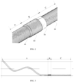
FIG. 1 is a cross-sectional diagram of a dynamic and static submarine cable provided by the present invention. -
FIG. 2 is a schematic structural diagram of a transition region of a dynamic and static submarine cable provided by the present invention. -
FIG. 3 is a schematic structural diagram of a dynamic and static submarine cable provided by the present invention. -
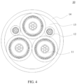
FIG. 4 is a schematic structural diagram of a cable core in an embodiment of the present invention. -
FIG. 5 is a schematic structural diagram of an electrical unit in an embodiment of the present invention. -
FIG. 6 is a schematic structural diagram of an optical unit in an embodiment of the present invention. -
FIG. 7 is a schematic diagram of an outer layer structure of a dynamic section according to the present invention. -
FIG. 8 is a schematic diagram of an outer layer structure of a static section according to the present invention. -
FIG. 9 is a schematic structural diagram of a half-ring part according to the present invention. -
FIG. 10 is a schematic axial cross-sectional diagram of a half-ring part in according to the present invention. -
FIG. 11 is a schematic axial cross-sectional diagram of another half-ring part in an embodiment of the present invention. - Description of reference numerals:
- 10: cable core; 11: electrical unit;
- 111: conductor; 112: inner semi-conductive shielding layer;
- 113: insulating layer; 114: outer semi-conductive shielding layer;
- 115: semi-conductive water-blocking layer; 116: metal shielding layer;
- 117: phase-splitting sheath layer; 12: optical unit;
- 121: optical fiber; 122: water-blocking filling;
- 123: outer casing; 124: inner semi-conductive sheath;
- 125: optical unit armor layer; 126: water-blocking tape;
- 127: outer semi-conductive sheath; 13: filler;
- 14: first sheath layer; 15: dynamic section;
- 16: static section; 17: transition section;
- 20: first armor layer; 30: inner cushion layer;
- 40: second armor layer; 50: second sheath layer;
- 60: third sheath layer; 70: transition device;
- 71: welding unit; 711: half-ring part;
- 712: welding fixing area; 713: smooth transition area.
- A dynamic and static submarine cable generally includes a dynamic cable and a static cable that are connected. Both the dynamic cable and the static cable include a cable core and an armor layer covering the cable core. Since the dynamic cable is arranged in seawater and the static cable is buried in the seabed, the static cable is subjected to less impact and wear than the dynamic cable. Therefore, the number of armor layers of the static cable is generally less than that of the dynamic cable, rendering different structures of the dynamic cable and the static cable. In the related art, the dynamic cable and the static cable are generally produced separately, and then a service joint box is used to connect cable cores and armor layers of the dynamic cable and the static cable to realize transition between the dynamic cable and the static cable so as to form a dynamic and static submarine cable. However, separately producing the dynamic cable and the static cable increases the production cycle, and the process of connecting the cable cores and the armor layers is time-consuming, which further increases the production cycle. In addition, connecting the dynamic cable core and the static cable core by the service joint box increases transmission loss of cable cores.
- In view of the above problems, a dynamic and static submarine cable provided by embodiments of the present invention includes a continuous cable core, where a first armor layer is arranged outside the cable core, a transition device is arranged on the first armor layer corresponding to a transition section of the cable core, and one end of a second armor layer is welded to the transition device, thereby realizing transition from double armor layers to one armor layer, and ensuring continuity of a production process of the dynamic and static submarine cable. In addition, the dynamic section and the static section can be in the same cable core, so that the dynamic and static submarine cable can be produced continuously without separate production, and thus there is no need to connect the dynamic cable core and the static cable core, thereby shortening the production cycle and reducing the transmission loss of the cable core.
- In order to make the above objectives, features and advantages of the embodiments according to the present invention clearer and understandable, the following clearly and completely describes the technical solutions in the embodiments according to the present invention with reference to the accompanying drawings in the embodiments according to the present invention. Apparently, the described embodiments are only some but not all of the embodiments according to the present invention. All other embodiments obtained by persons of ordinary skill in the art based on the embodiments according to the present invention without creative efforts shall fall within the protection scope of the present invention.
- As shown in
FIG. 1 , an embodiment of the present invention provides a dynamic and static submarine cable, including acable core 10, afirst armor layer 20, atransition device 70 and asecond armor layer 40. Thecable core 10 includes adynamic section 15, astatic section 16 and atransition section 17 connecting thedynamic section 15 and thestatic section 16, and thedynamic section 15, thestatic section 16 and thetransition section 17 are of an integral structure. Thefirst armor layer 20 is sleeved outside thedynamic section 15, thestatic section 16 and thetransition section 17. Thetransition device 70 is sleeved outside thefirst armor layer 20 corresponding to thetransition section 17. Thesecond armor layer 40 is sleeved outside thefirst armor layer 20 corresponding to thedynamic section 15, and has a first end covering part of thetransition device 70 and welded to an outer peripheral surface of thetransition device 70. - The first end of the
second armor layer 40 is an end of thesecond armor layer 40 close to thestatic section 16, and a dynamic and static submarine cable section corresponding to thestatic section 16 can be understood as a static cable, such as a section C as shown inFIGS. 2 and 3 ; a dynamic and static submarine cable section corresponding to thedynamic section 15 can be understood as a dynamic cable, such as a section A as shown inFIGS. 2 and 3 ; and a dynamic and static submarine cable section corresponding to thetransition section 17 can be understood as a transition cable, such as a section B as shown inFIGS. 2 and 3 . Thetransition device 70 may be ring-shaped, and the ring-shapedtransition device 70 is sleeved outside thefirst armor layer 20 corresponding to thetransition section 17. - The dynamic and static submarine cable provided by the embodiment of the present invention has the
cable core 10. Thedynamic section 15, thestatic section 16 and thetransition section 17 in thecable core 10 are of an integral structure. Thefirst armor layer 20 is provided on an outside of thecable core 10. By arranging thetransition device 70 on thefirst armor layer 20 corresponding to thetransition section 17, and welding one end of thesecond armor layer 40 to thetransition device 70, the transition from the armor layer of the dynamic section to the armor layer of the static section can be completed, therefore, the continuity of a production process of the dynamic and static submarine cable is guaranteed. With such arrangement, the dynamic section and the static section can be in the same cable core, so that the dynamic and static submarine cable can be produced continuously without separate production, and thus there is no need to connect the dynamic cable core and the static cable core, thereby shortening the production cycle and reducing the transmission loss of thecable core 10. - Referring to
FIG. 4 , the dynamic and static submarine cable provided by the embodiment of the present invention includes thecable core 10. Thecable core 10 includes a plurality of electrical units 11 and a plurality ofoptical units 12, and the plurality of electrical units 11 and the plurality ofoptical units 12 are stranded. - The electrical units 11 are applicable to conducting electricity and transmitting signals, and the number of the electrical units 11 may be 1, 2, 3, etc. In this embodiment, the number of the electrical units 11 is 3. The number of the
optical units 12 may be 1, 2, 3, etc. In this embodiment, the number of theoptical units 12 is 2. - Referring to
FIG. 5 , in a specific embodiment, each electrical unit 11 includes, from inside to outside in a radial direction, an electrical unit core, an innersemi-conductive shielding layer 112, an insulatinglayer 113, an outersemi-conductive shielding layer 114, a semi-conductive water-blocking layer 115, ametal shielding layer 116 and a phase-splittingsheath layer 117, where the electrical unit core includes a plurality of strandedconductors 111. Theconductors 111 may be copper conductors, aluminum conductors, or the like. - The inner
semi-conductive shielding layer 112 covers an outer peripheral surface of the electrical unit core, and may be used to avoid partial discharge between theconductors 111 and the insulatinglayer 113. The insulatinglayer 113 covers an outer peripheral surface of the innersemi-conductive shielding layer 112, and may be used to insulate the electrical unit core from external environment or adjacent electrical unit cores, thereby ensuring electrical performance of the dynamic and static submarine cable. Exemplarily, the insulatinglayer 113 may be formed by extrusion cladding. - The outer
semi-conductive shielding layer 114 covers an outer peripheral surface of the insulatinglayer 113, and may be used to prevent partial discharge between the insulatinglayer 113 and themetal shielding layer 116 due to defects such as cracks on a surface of the insulatinglayer 113. The semi-conductive water-blocking layer 115 covers an outer peripheral surface of the outersemi-conductive shielding layer 114, and may play a role of blocking water. Themetal shielding layer 116 covers an outer peripheral surface of the semi-conductive water-blocking layer 115. Themetal shielding layer 116 may be a copper tape shielding layer, a steel tape shielding layer, an aluminum-plastic composite tape shielding layer and other composite tape shielding layers, and can shield electromagnetic interference. The phase-splittingsheath layer 117 covers an outer peripheral surface of themetal shielding layer 116, this can avoid direct contact betweenmetal shielding layers 116 of the plurality of electrical units, thereby avoiding abrasion between the metal shielding layers 116 of the plurality of electrical units and playing a role of water resistance and blocking water. In this embodiment, the phase-splittingsheath layer 117 is an extruded sheath layer. - The
optical unit 12 provided by an embodiment of the present invention includes anoptical fiber 121 and a protective layer covering an outer peripheral surface of theoptical fiber 121, and the optical unit may be used to transmit signals. Exemplarily, referring toFIG. 6 , the optical unit includes anouter casing 123 and a plurality ofoptical fibers 121 arranged inside the outer casing. The outer casing may be a stainless steel tube. Water-blockingfillings 122 are further arranged between the plurality ofoptical fibers 121 in theouter casing 123. Along a radial direction of theouter casing 123, an outer peripheral surface of theouter casing 123 is covered sequentially with an innersemi-conductive sheath 124, an opticalunit armor layer 125; a water-blockingtape 126; and an outersemi-conductive sheath 127. - In some embodiments, not covered by claims, the
cable core 10 further includes a central reinforcing member, and the plurality of optical units 11 and the plurality ofelectrical units 12 are stranded around the central reinforcing member. The central reinforcing member may be a metal wire or a non-metallic wire. Tension resistance and balance of thecable core 10 can be enhanced by arranging the central reinforcing member. - Further, in embodiments not covered by claims, the
cable core 10 further includesfillers 13 filled in stranded gaps between the plurality ofoptical units 12 and the plurality of electrical units 11, and thefillers 13 may be filling strips, filling ropes and the like. - Referring to
FIG. 4 , in some specific embodiments, thecable core 10 further includes afirst sheath layer 14, and thefirst sheath layer 14 covers an outside of the stranded electrical units 11 andoptical units 12. Arrangement of thefirst sheath layer 14, not covered by claims, can ensure water-blocking performance of thecable core 10. In this embodiment, thefirst sheath layer 14 is an extruded sheath layer. - Referring to
FIG. 1 , thecable core 10 provided by the embodiment of the present invention axially includes thedynamic section 15, thestatic section 16 and thetransition section 17 connecting thedynamic section 15 and thestatic section 16, and thedynamic section 15, thestatic section 16 and thetransition section 17 are of an integral structure, where thedynamic section 15 corresponds to a dynamic cable, and thestatic section 16 corresponds to a static cable. With such arrangement, during the manufacturing process, cable cores of the dynamic cable and the static cable can be continuously produced without separate manufacturing, thereby shortening the production cycle. There is also no need to connect the dynamic cable core and the static cable core, thereby reducing transmission loss of thecable core 10 and improving performance stability of thecable core 10. - The
first armor layer 20 is sleeved outside thedynamic section 15, thestatic section 16 and thetransition section 17, and thefirst armor layer 20 is continuous. Both thefirst armor layer 20 and thesecond armor layer 40 may be formed by stranding or braiding metal wires such as steel wires. With such arrangement, in the manufacturing process, thefirst armor layer 20 of the dynamic and static submarine cable can be continuously produced without separate manufacturing, thereby shortening the production cycle. - Referring to
FIGS. 1 ,7 and 8 , the dynamic and static submarine cable provided by the embodiment of the present invention further includes thetransition device 70 and thesecond armor layer 40. Thetransition device 70 is sleeved outside thefirst armor layer 20 corresponding to thetransition section 17. Thesecond armor layer 40 is sleeved outside thefirst armor layer 20 corresponding to thedynamic section 15. The first end of thesecond armor layer 40 covers part of thetransition device 70, and is welded to the outer peripheral surface of thetransition device 70. With such arrangement, transition between the armor layer of the dynamic cable and the armor layer of the static cable can be realized. - Further, in embodiments not covered by claims, an
inner cushion layer 30 may also be arranged between thesecond armor layer 40 and thefirst armor layer 20. With such arrangement, direct contact between thesecond armor layer 40 and thefirst armor layer 20 can be avoided, and mutual abrasion between thesecond armor layer 40 and thefirst armor layer 20 is thereby avoided. - Referring to
FIG. 7 , in some embodiments, an outer peripheral surface of thesecond armor layer 40 is further covered with asecond sheath layer 50. Thesecond sheath layer 50 may be an extruded sheath layer, and material of thesecond sheath layer 50 can be PE material. An outer peripheral surface of thefirst armor layer 20 corresponding to thestatic section 16 is further covered with athird sheath layer 60. Thethird sheath layer 60 may be a wrapping sheath layer, and material of thethird sheath layer 60 may be PP winding rope. - According to the invention, referring to
FIG. 9 , thetransition device 70 includes a heat transfer unit and a welding unit 71. The heat transfer unit covers an outside of thefirst armor layer 20 corresponding to thetransition section 17, and the welding unit 71 is an annular structure and is sleeved outside the heat transfer unit. The first end of thesecond armor layer 40 is welded to an outer peripheral surface of the welding unit 71. The heat transfer unit can release heat during a welding process, and at the same time acts as an isolation buffer layer to ensure welding quality. The heat transfer unit is a metal tape wrapped around an outer peripheral surface of thefirst armor layer 20 corresponding to thetransition section 17. - In some possible embodiments, an inner peripheral surface and the outer peripheral surface of the welding unit 71 are respectively arranged with an anti-corrosion coating. By arranging the anti-corrosion coating, corrosion resistance of the welding unit 71 can be improved, thereby increasing service life of the welding unit 71. Exemplarily, material of the anti-corrosion coating is a composite material with good stability, which can maintain good anti-corrosion performance in both high temperature and low temperature environments.
- Referring to
FIG. 9 , according to the invention, the welding unit 71 is of a half type, including two half-ring parts 711. The two half-ring parts 711 are of a split structure. Inner ring surfaces of the two half-ring parts 711 are opposite, and two ends of one half-ring part 711 along a circumferential direction thereof are connected to two ends of the other half-ring part 711 along a circumferential direction thereof in a one-to-one relationship. Exemplarily, a mode of connecting the two half-ring parts 711 is welding. With such arrangement, the welding unit 71 can be directly sleeved outside the heat transfer unit, without inserting and moving the welding unit 71 from one end of the dynamic and static submarine cable to the outside of the heat transfer unit along an axis of the dynamic and static submarine cable, and the operation is thus more convenient. - Further, along an axial direction of each half-
ring part 711, each half-ring part 711 includes awelding fixing area 712 and twosmooth transition areas 713 respectively connected to two ends of thewelding fixing area 712. A thickness of thewelding fixing area 712 is greater than thicknesses of thesmooth transition areas 713. The first end of thesecond armor layer 40 is welded to an outer peripheral surface of thewelding fixing area 712. With such arrangement, heat generated during a process of welding the first end of thesecond armor layer 40 can be better transferred. - Referring to
FIG. 10 , in some specific embodiments, along the axial direction of each half-ring part 711, the thickness of the half-ring part 711 changes continuously, that is, the thicknesses at junctions between thesmooth transition areas 713 and thewelding fixing area 712 do not change abruptly. - Further, referring to
FIG. 10 , on an axial cross-section of each half-ring part 711, the thicknesses of thesmooth transition areas 713 decrease linearly along a direction away from thewelding fixing area 712. With such arrangement, metal wires at the first end of thesecond armor layer 40 can better fit to the welding unit 71, thereby improving strength and stability of the welding. - Further, along the axial direction of each half-
ring part 711, the thickness of the welding fixing area does not change. On the axial cross-section of each half-ring part 711, a minimum thickness of each of thesmooth transition areas 713 is 20% of the thickness of thewelding fixing area 712. The axial cross-section is a cross section of an axis passing through the half-ring part 711. Referring toFIG. 10 , the minimum thickness of thesmooth transition areas 713 is at ends of thesmooth transition areas 713 away from thewelding fixing area 712. Such arrangement can not only make the metal wires at the first end of thesecond armor layer 40 better fit to the welding unit 71, but also rapidly conduct and reduce welding heat and avoid damage to a structure of thecable core 10. - In some embodiments, the half-
ring part 711 has a middle part protruding outwards, and is presented in a circular arch shape. Along the axial direction of the half-ring part 711, a thickness of the circular arch shaped structure located at an edge of the half-ring part is equal to 20% of a thickness of the circular arch shaped structure located at a middle of the half-ring part. - Exemplarily, a welding point between the first end of the
second armor layer 40 and thewelding fixing area 712 is further coated with an anti-corrosion coating, so as to improve anti-corrosion performance at the welding point. For the material of the anti-corrosion coating, reference may be made to the above description. - In some other specific embodiments, referring to
FIG. 11 , along the axial direction of the half-ring part 711, the thickness of thewelding fixing area 712 and the thicknesses of thesmooth transition areas 713 are all constant, and the thicknesses of thesmooth transition areas 713 are equal to 20% of the thickness of thewelding fixing area 712, and a transition portion is further arranged between thewelding fixing area 712 and eachsmooth transition area 713. - Claim 7 of the present invention further provides a method for manufacturing a dynamic and static submarine cable, including:
- providing a cable core, which includes a dynamic section, a static section, and a transition section connecting the dynamic section and the static section, where the dynamic section, the static section, and the transition section are of an integral structure because of which the cable core can be continuously produced;
- marking demarcation points of the dynamic section, the static section and the transition section on an outer peripheral surface of the dynamic section, an outer peripheral surface of the static section and an outer peripheral surface of the transition section, respectively;
- stranding a first armor layer on an outer peripheral surface of the cable core;
- winding a metal tape around an outer peripheral surface of the first armor layer corresponding to the transition section, to form a heat transfer unit, where exemplarily, the metal tape is evenly wound around the outer peripheral surface of the first armor layer corresponding to the transition section;
- having a welding unit sleeved on an outer peripheral surface of the heat transfer unit;
- stranding a second armor layer on an outer peripheral surface of the first armor layer corresponding to the dynamic section, and making an first end of the second armor layer cover part of the welding unit; and
- welding the first end of the second armor layer to an outer peripheral surface of the welding unit, wherein the welding unit comprises two half-ring parts, and each of the half-ring parts comprises, along an axial direction thereof, a welding fixing area, and two smooth transition areas respectively connected to two ends of the welding fixing area; and wherein a thickness of the welding fixing area is greater than thicknesses of the smooth transition areas, and the first end of the second armor layer is welded to an outer peripheral surface of the welding fixing area.
- Neither separate production of the dynamic cable and the static cable nor connection of the dynamic cable core and the static cable core is required by the method for manufacturing the dynamic and static submarine cable provided by the embodiment, thereby shortening the production cycle and reducing the transmission loss of the cable core.
- Exemplarily, for structures and materials of the cable core and the welding unit in the above-mentioned method embodiments, reference may be made to the above-mentioned product embodiments, which will not be repeated here.
- According to the invention, in the step of having the welding unit sleeved on the outer peripheral surface of the heat transfer unit, the welding unit includes two half-ring parts. The two half-ring parts are of a split structure. Inner ring surfaces of the two half-ring parts are opposite, and two ends of one half-ring part along the circumferential direction thereof are connected to two ends of the other half-ring part along the circumferential direction thereof in a one-to-one relationship. Exemplarily, a spot welding machine may be used to weld the two half-ring parts, so as to fix a position of the welding unit.
- Exemplarily, in the step of welding the first end of the second armor layer to the outer peripheral surface of the welding unit, the first end of the second armor layer is welded to the welding fixing area of the welding unit, with welding points evenly distributed. During the welding process, metal wires at the first end of the second armor layer fit snugly to the smooth transition areas to ensure a reliable and stable welding process. Further, reservation and confirmation of a position of the second armor layer are also included before welding. The welding position is located in the middle of the welding fixing area. After the welding is completed, an anti-corrosion coating may be applied to outsides of the welding points.
- After the step of welding the first end of the second armor layer to the outer peripheral surface of the welding unit, the following are further included:
- having a second sheath layer cover an outer peripheral surface of the second armor layer; and
- having a third sheath layer cover an outer peripheral surface of the first armor layer corresponding to the static section.
- Exemplarily, for structures of the second sheath layer and the third sheath layer, reference may be made to the above-mentioned product embodiments, which will not be repeated here.
- In some embodiments, not coverdd by claims, armor layers of the dynamic and static submarine cable include not only the first armor layer and the second armor layer, but also a third armor layer, a fourth armor layer and so on. At this point, after the step of welding the first end of the second armor layer to the outer peripheral surface of the welding unit, the following is further included:
having a further transition device sleeved outside the second armor layer, where the further transition device may be sleeved at any position outside the second armor layer, and for the structure of the further transition device, reference may be made to the above-mentioned product embodiments, which will not be repeated here; and then stranding the third armor layer on the outer peripheral surface of the second armor layer, and welding a first end of the third armor layer to an outer peripheral surface of this outermost welding unit, with a second end of the third armor layer aligned with an end of the second armor layer. Similarly, the above steps may be repeated when more armor layers such as a fourth armor layer and a fifth armor layer are included. - Embodiments or implementations in the present specification are described in a progressive manner. Description of each embodiment focuses on a difference from other embodiments, and references may be made to each other for same or similar parts among respective embodiments.
- Those skilled in the art should understand that in the disclosure of the present invention, terms such as "longitudinal", "transverse", "upper", "lower", "front", "rear", "left", "right", "vertical", "horizontal", "top", "bottom", "inner", and "outer", etc. refer to orientations or positional relationships based on orientations or positional relationships illustrated in the accompanying drawings, which are only to facilitate and simplify descriptions of the present invention, rather than to indicate or imply that the system or element referred to must be of a particular orientation or must be constructed and operate in a particular orientation, and therefore the above terms should not be construed as limiting the present invention.
- Reference throughout the present specification to "an embodiment," "some embodiments," "an illustrative embodiment," "an example," "a specific example," or "some examples" means that a particular feature, structure, material, or characteristic described in connection with the embodiment or example is included in at least one embodiment or example of the present invention. Thus, the indicative descriptions of the above terms in the present specification are not necessarily referring to the same embodiment or example. Furthermore, the particular features, structures, materials, or characteristics described may be combined in any suitable manner in one or more embodiments or examples.
Claims (8)
- A dynamic and static submarine cable, comprising:
a cable core (10) comprising:a dynamic section (15),a static section (16), anda transition section (17) connecting the dynamic section (15) and the static section (16),wherein the dynamic section (15), the static section (16), and the transition section (17) are of an integral structure;a first armor layer (20) sleeved outside the dynamic section (15), the static section (16) and the transition section (17); anda second armor layer (40) sleeved outside the first armor layer (20) corresponding to the dynamic section (15),characterized by further comprising:a transition device (70) sleeved outside the first armor layer (20) corresponding to the transition section (17); andthe second armor layer (40) having a first end covering part of the transition device (70) and welded to an outer peripheral surface of the transition device (70);wherein the transition device (70) comprises a heat transfer unit and a welding unit (71), and the heat transfer unit covers an outside of the first armor layer (20) corresponding to the transition section (17);the welding unit (71) is of an annular structure and is sleeved outside the heat transfer unit; andthe first end of the second armor layer (40) is welded to an outer peripheral surface of the welding unit (71);wherein the welding unit (71) comprises two half-ring parts (711), and each of the half-ring parts (711) comprises, along an axial direction thereof, a welding fixing area (712), and two smooth transition areas (713) respectively connected to two ends of the welding fixing area (712); andwherein a thickness of the welding fixing area (712) is greater than thicknesses of the smooth transition areas (713), and the first end of the second armor layer (40) is welded to an outer peripheral surface of the welding fixing area (712). - The dynamic and static submarine cable according to claim 1, wherein an inner peripheral surface and the outer peripheral surface of the welding unit (71) are respectively arranged with an anti-corrosion coating.
- The dynamic and static submarine cable according to claim 1, wherein on an axial cross-section of each of the half-ring parts (711), the thicknesses of the smooth transition areas (713) decrease linearly along a direction away from the welding fixing area (712).
- The dynamic and static submarine cable according to claim 3, wherein a minimum thickness of each of the smooth transition areas (713) is 20% of the thickness of the welding fixing area (712).
- The dynamic and static submarine cable according to any one of claims 1 to 4, wherein the cable core (10) comprises a plurality of electrical units (11) and a plurality of optical units (12), and the plurality of electrical units (11) and the plurality of optical units (12) are stranded;each of the electrical units (11) comprises, from inside to outside in a radial direction, an electrical unit core, an inner semi-conductive shielding layer (112), an insulating layer (113), an outer semi-conductive shielding layer (114), a semi-conductive water-blocking layer (115), a metal shielding layer (116), and a phase-splitting sheath layer (117), wherein the electrical unit core comprises a plurality of stranded conductors (111); andeach of the optical units (12) comprises an optical fiber (121) and a protective layer covering an outer peripheral surface of the optical fiber (121).
- The dynamic and static submarine cable according to claim 5, wherein the cable core (10) further comprises a first sheath layer (14), and the first sheath layer (14) covers an outside of the stranded electrical units (11) and optical units (12).
- A method for manufacturing a dynamic and static submarine cable, comprising the following steps:providing a cable core (10) comprising a dynamic section (15), a static section (16), and a transition section (17) connecting the dynamic section (15) and the static section (16), wherein the dynamic section (15), the static section (16), and the transition section (17) are of an integral structure;marking demarcation points of the dynamic section (15), the static section (16) and the transition section (17) on an outer peripheral surface of the cable core (10);stranding a first armor layer (20) on an outer peripheral surface of the dynamic section (15), on an outer peripheral surface of the static section (16), and on an outer peripheral surface of the transition section (17);winding a metal tape around an outer peripheral surface of the first armor layer (20) corresponding to the transition section (17), to form a heat transfer unit;having a welding unit (71) sleeved on an outer peripheral surface of the heat transfer unit;stranding a second armor layer (40) on an outer peripheral surface of the first armor layer (20) corresponding to the dynamic section (15), and making an first end of the second armor layer (40) cover part of the welding unit (71); andwelding the first end of the second armor layer (40) to an outer peripheral surface of the welding unit (71);wherein the welding unit (71) comprises two half-ring parts (711), and each of the half-ring parts (711) comprises, along an axial direction thereof, a welding fixing area (712), and two smooth transition areas (713) respectively connected to two ends of the welding fixing area (712); andwherein a thickness of the welding fixing area (712) is greater than thicknesses of the smooth transition areas (713), and the first end of the second armor layer (40) is welded to an outer peripheral surface of the welding fixing area (712).
- The method for manufacturing the dynamic and static submarine cable according to claim 7, wherein
after the step of welding the first end of the second armor layer (40) to the welding unit (71), the method further comprises:having a second sheath layer (50) cover an outer peripheral surface of the second armor layer (40); andhaving a third sheath layer (60) cover an outer peripheral surface of the first armor layer (20) corresponding to the static section (16).
Applications Claiming Priority (2)
| Application Number | Priority Date | Filing Date | Title |
|---|---|---|---|
| CN202110559909.0A CN113299431B (en) | 2021-05-21 | 2021-05-21 | Dynamic and static submarine cable and manufacturing method thereof |
| PCT/CN2021/105165 WO2022241926A1 (en) | 2021-05-21 | 2021-07-08 | Dynamic and static submarine cable and manufacturing method therefor |
Publications (4)
| Publication Number | Publication Date |
|---|---|
| EP4207216A1 EP4207216A1 (en) | 2023-07-05 |
| EP4207216A4 EP4207216A4 (en) | 2024-04-10 |
| EP4207216C0 EP4207216C0 (en) | 2025-02-26 |
| EP4207216B1 true EP4207216B1 (en) | 2025-02-26 |
Family
ID=77323878
Family Applications (1)
| Application Number | Title | Priority Date | Filing Date |
|---|---|---|---|
| EP21940375.5A Active EP4207216B1 (en) | 2021-05-21 | 2021-07-08 | Dynamic and static submarine cable and manufacturing method therefor |
Country Status (5)
| Country | Link |
|---|---|
| EP (1) | EP4207216B1 (en) |
| CN (1) | CN113299431B (en) |
| ES (1) | ES3018111T3 (en) |
| PL (1) | PL4207216T3 (en) |
| WO (1) | WO2022241926A1 (en) |
Families Citing this family (5)
| Publication number | Priority date | Publication date | Assignee | Title |
|---|---|---|---|---|
| DE102021131422A1 (en) | 2021-11-30 | 2023-06-01 | Rwe Renewables Gmbh | Submarine cable system and method of laying a submarine cable system |
| CN114530282B (en) * | 2021-12-20 | 2024-02-23 | 烽火海洋网络设备有限公司 | Cable type transition joint with different armored structures for submarine cables and online transition method thereof |
| CN120345040A (en) * | 2022-11-30 | 2025-07-18 | Ls电线有限公司 | Submarine cables |
| EP4560651A1 (en) * | 2023-11-21 | 2025-05-28 | NKT HV Cables AB | A submarine power cable |
| CN119132706A (en) * | 2024-09-06 | 2024-12-13 | 中天科技海缆股份有限公司 | Submarine cable suitable for floating wind power and processing method thereof |
Family Cites Families (11)
| Publication number | Priority date | Publication date | Assignee | Title |
|---|---|---|---|---|
| CN201918202U (en) * | 2011-01-14 | 2011-08-03 | 宁波东方电缆股份有限公司 | Submarine cable for floating platform |
| CN205283073U (en) * | 2015-12-07 | 2016-06-01 | 江苏亨通海洋光网系统有限公司 | Cable type transition joint of sea cable |
| CN206023162U (en) * | 2016-08-29 | 2017-03-15 | 中天海洋系统有限公司 | A kind of connection seabed dynamic cable and the piecing devices of seabed static state cable |
| KR101805668B1 (en) * | 2016-09-29 | 2017-12-06 | 삼성중공업 주식회사 | Riser buoyancy control apparatus |
| CN208849433U (en) * | 2018-09-06 | 2019-05-10 | 青岛汉缆股份有限公司 | Boundling dynamic sea cable middle transition section attachment device |
| EP3644326B1 (en) * | 2018-10-26 | 2022-07-27 | NKT HV Cables AB | Reinforced submarine power cable |
| EP3671771B1 (en) * | 2018-12-21 | 2023-02-08 | Nexans | Cable sheathing of a pb-ca-sn alloy and method of manufacture thereof |
| CN109727718B (en) * | 2018-12-24 | 2020-04-24 | 江苏亨通高压海缆有限公司 | Bunched submarine cable and dynamic and static transition method thereof |
| CN111292889A (en) * | 2020-02-20 | 2020-06-16 | 中天科技海缆有限公司 | Dynamic and static armored cable and manufacturing method thereof |
| CN111477393B (en) * | 2020-04-24 | 2021-09-28 | 中海石油(中国)有限公司 | Dynamic submarine cable and static submarine cable transition assembly and preparation method thereof |
| CN111899927B (en) * | 2020-07-16 | 2021-11-23 | 中天科技海缆股份有限公司 | Dynamic and static submarine cable with continuous cable core and production method thereof |
-
2021
- 2021-05-21 CN CN202110559909.0A patent/CN113299431B/en active Active
- 2021-07-08 PL PL21940375.5T patent/PL4207216T3/en unknown
- 2021-07-08 EP EP21940375.5A patent/EP4207216B1/en active Active
- 2021-07-08 ES ES21940375T patent/ES3018111T3/en active Active
- 2021-07-08 WO PCT/CN2021/105165 patent/WO2022241926A1/en not_active Ceased
Also Published As
| Publication number | Publication date |
|---|---|
| ES3018111T3 (en) | 2025-05-14 |
| EP4207216A1 (en) | 2023-07-05 |
| WO2022241926A1 (en) | 2022-11-24 |
| EP4207216A4 (en) | 2024-04-10 |
| PL4207216T3 (en) | 2025-04-28 |
| CN113299431B (en) | 2022-04-15 |
| EP4207216C0 (en) | 2025-02-26 |
| CN113299431A (en) | 2021-08-24 |
Similar Documents
| Publication | Publication Date | Title |
|---|---|---|
| EP4207216A1 (en) | Dynamic and static submarine cable and manufacturing method therefor | |
| US9722406B2 (en) | Undersea cable, undersea cable installation structure, and method for installing undersea cable | |
| CN113571245A (en) | Deep water submarine cable | |
| CN113782264B (en) | Submarine cable | |
| CN111292883B (en) | Light-duty nonmetal armor submarine cable | |
| KR20200047419A (en) | Reinforced submarine power cable | |
| CN210006533U (en) | direct current submarine cable for deep sea | |
| CN118888189B (en) | Umbilical cable | |
| CN115862935B (en) | DC composite submarine cable and its manufacturing method | |
| JP2015038841A (en) | Water/water bottom cable | |
| CN113077926A (en) | High-current-carrying corrosion-resistant long-life high-pressure submarine cable | |
| CN209747202U (en) | Underwater communication cable | |
| CN111292889A (en) | Dynamic and static armored cable and manufacturing method thereof | |
| CN217902754U (en) | Dynamic submarine cable | |
| CN113393959B (en) | Submarine cable and manufacturing method and coating equipment thereof | |
| CN107301890B (en) | WMF high-toughness low-stress load-bearing detection cable | |
| CN222826108U (en) | An ultra-deepwater dynamic hose umbilical cable | |
| CN221427398U (en) | Sea cable with split water-blocking conductors | |
| CN117790052B (en) | A built-in optical fiber DC dynamic composite submarine power cable and its manufacturing method | |
| CN111653401A (en) | Steel wire armored submarine cable design method | |
| JP2017135121A (en) | Electric power underwater / underwater cable track | |
| CN222421393U (en) | Composite cable | |
| CN218100764U (en) | Waterproof and moistureproof sheath cable | |
| CN112750557A (en) | Photoelectric composite trailing cable and manufacturing method thereof | |
| CN217157754U (en) | Super-large width-thickness ratio heat-resistant long-life wire for suspension module |
Legal Events
| Date | Code | Title | Description |
|---|---|---|---|
| STAA | Information on the status of an ep patent application or granted ep patent |
Free format text: STATUS: THE INTERNATIONAL PUBLICATION HAS BEEN MADE |
|
| PUAI | Public reference made under article 153(3) epc to a published international application that has entered the european phase |
Free format text: ORIGINAL CODE: 0009012 |
|
| STAA | Information on the status of an ep patent application or granted ep patent |
Free format text: STATUS: REQUEST FOR EXAMINATION WAS MADE |
|
| 17P | Request for examination filed |
Effective date: 20230329 |
|
| AK | Designated contracting states |
Kind code of ref document: A1 Designated state(s): AL AT BE BG CH CY CZ DE DK EE ES FI FR GB GR HR HU IE IS IT LI LT LU LV MC MK MT NL NO PL PT RO RS SE SI SK SM TR |
|
| A4 | Supplementary search report drawn up and despatched |
Effective date: 20240312 |
|
| RIC1 | Information provided on ipc code assigned before grant |
Ipc: H01B 13/26 20060101ALI20240305BHEP Ipc: H01B 11/22 20060101ALI20240305BHEP Ipc: H01B 9/00 20060101ALI20240305BHEP Ipc: H01B 7/18 20060101ALI20240305BHEP Ipc: H01B 7/24 20060101ALI20240305BHEP Ipc: H01B 7/22 20060101ALI20240305BHEP Ipc: H01B 7/14 20060101AFI20240305BHEP |
|
| STAA | Information on the status of an ep patent application or granted ep patent |
Free format text: STATUS: EXAMINATION IS IN PROGRESS |
|
| 17Q | First examination report despatched |
Effective date: 20240624 |
|
| DAV | Request for validation of the european patent (deleted) | ||
| DAX | Request for extension of the european patent (deleted) | ||
| GRAP | Despatch of communication of intention to grant a patent |
Free format text: ORIGINAL CODE: EPIDOSNIGR1 |
|
| STAA | Information on the status of an ep patent application or granted ep patent |
Free format text: STATUS: GRANT OF PATENT IS INTENDED |
|
| INTG | Intention to grant announced |
Effective date: 20241204 |
|
| GRAS | Grant fee paid |
Free format text: ORIGINAL CODE: EPIDOSNIGR3 |
|
| GRAA | (expected) grant |
Free format text: ORIGINAL CODE: 0009210 |
|
| STAA | Information on the status of an ep patent application or granted ep patent |
Free format text: STATUS: THE PATENT HAS BEEN GRANTED |
|
| AK | Designated contracting states |
Kind code of ref document: B1 Designated state(s): AL AT BE BG CH CY CZ DE DK EE ES FI FR GB GR HR HU IE IS IT LI LT LU LV MC MK MT NL NO PL PT RO RS SE SI SK SM TR |
|
| REG | Reference to a national code |
Ref country code: GB Ref legal event code: FG4D |
|
| REG | Reference to a national code |
Ref country code: CH Ref legal event code: EP |
|
| REG | Reference to a national code |
Ref country code: DE Ref legal event code: R096 Ref document number: 602021026962 Country of ref document: DE |
|
| REG | Reference to a national code |
Ref country code: IE Ref legal event code: FG4D |
|
| U01 | Request for unitary effect filed |
Effective date: 20250320 |
|
| REG | Reference to a national code |
Ref country code: GR Ref legal event code: EP Ref document number: 20250400530 Country of ref document: GR Effective date: 20250409 |
|
| U07 | Unitary effect registered |
Designated state(s): AT BE BG DE DK EE FI FR IT LT LU LV MT NL PT RO SE SI Effective date: 20250326 |
|
| PG25 | Lapsed in a contracting state [announced via postgrant information from national office to epo] |
Ref country code: RS Free format text: LAPSE BECAUSE OF FAILURE TO SUBMIT A TRANSLATION OF THE DESCRIPTION OR TO PAY THE FEE WITHIN THE PRESCRIBED TIME-LIMIT Effective date: 20250526 |
|
| PGFP | Annual fee paid to national office [announced via postgrant information from national office to epo] |
Ref country code: PL Payment date: 20250627 Year of fee payment: 5 |
|
| PG25 | Lapsed in a contracting state [announced via postgrant information from national office to epo] |
Ref country code: HR Free format text: LAPSE BECAUSE OF FAILURE TO SUBMIT A TRANSLATION OF THE DESCRIPTION OR TO PAY THE FEE WITHIN THE PRESCRIBED TIME-LIMIT Effective date: 20250226 |
|
| U20 | Renewal fee for the european patent with unitary effect paid |
Year of fee payment: 5 Effective date: 20250709 |
|
| PG25 | Lapsed in a contracting state [announced via postgrant information from national office to epo] |
Ref country code: SM Free format text: LAPSE BECAUSE OF FAILURE TO SUBMIT A TRANSLATION OF THE DESCRIPTION OR TO PAY THE FEE WITHIN THE PRESCRIBED TIME-LIMIT Effective date: 20250226 |
|
| PGFP | Annual fee paid to national office [announced via postgrant information from national office to epo] |
Ref country code: ES Payment date: 20250807 Year of fee payment: 5 |
|
| PGFP | Annual fee paid to national office [announced via postgrant information from national office to epo] |
Ref country code: GR Payment date: 20250716 Year of fee payment: 5 Ref country code: NO Payment date: 20250709 Year of fee payment: 5 |
|
| PGFP | Annual fee paid to national office [announced via postgrant information from national office to epo] |
Ref country code: GB Payment date: 20250703 Year of fee payment: 5 |
|
| PG25 | Lapsed in a contracting state [announced via postgrant information from national office to epo] |
Ref country code: CZ Free format text: LAPSE BECAUSE OF FAILURE TO SUBMIT A TRANSLATION OF THE DESCRIPTION OR TO PAY THE FEE WITHIN THE PRESCRIBED TIME-LIMIT Effective date: 20250226 |
|
| PGFP | Annual fee paid to national office [announced via postgrant information from national office to epo] |
Ref country code: IE Payment date: 20250702 Year of fee payment: 5 |
|
| PG25 | Lapsed in a contracting state [announced via postgrant information from national office to epo] |
Ref country code: SK Free format text: LAPSE BECAUSE OF FAILURE TO SUBMIT A TRANSLATION OF THE DESCRIPTION OR TO PAY THE FEE WITHIN THE PRESCRIBED TIME-LIMIT Effective date: 20250226 |
|
| PGFP | Annual fee paid to national office [announced via postgrant information from national office to epo] |
Ref country code: IS Payment date: 20250709 Year of fee payment: 5 |
|
| PLBE | No opposition filed within time limit |
Free format text: ORIGINAL CODE: 0009261 |
|
| STAA | Information on the status of an ep patent application or granted ep patent |
Free format text: STATUS: NO OPPOSITION FILED WITHIN TIME LIMIT |
|
| REG | Reference to a national code |
Ref country code: CH Ref legal event code: L10 Free format text: ST27 STATUS EVENT CODE: U-0-0-L10-L00 (AS PROVIDED BY THE NATIONAL OFFICE) Effective date: 20260107 |
|
| 26N | No opposition filed |
Effective date: 20251127 |
|
| REG | Reference to a national code |
Ref country code: CH Ref legal event code: H13 Free format text: ST27 STATUS EVENT CODE: U-0-0-H10-H13 (AS PROVIDED BY THE NATIONAL OFFICE) Effective date: 20260224 |
|
| PG25 | Lapsed in a contracting state [announced via postgrant information from national office to epo] |
Ref country code: CH Free format text: LAPSE BECAUSE OF NON-PAYMENT OF DUE FEES Effective date: 20250731 |