EP4207084A1 - 3d virtual-reality display device, head-mounted display, and 3d virtual-reality display method - Google Patents
3d virtual-reality display device, head-mounted display, and 3d virtual-reality display method Download PDFInfo
- Publication number
- EP4207084A1 EP4207084A1 EP20951378.7A EP20951378A EP4207084A1 EP 4207084 A1 EP4207084 A1 EP 4207084A1 EP 20951378 A EP20951378 A EP 20951378A EP 4207084 A1 EP4207084 A1 EP 4207084A1
- Authority
- EP
- European Patent Office
- Prior art keywords
- real
- virtual reality
- image
- real object
- display
- Prior art date
- Legal status (The legal status is an assumption and is not a legal conclusion. Google has not performed a legal analysis and makes no representation as to the accuracy of the status listed.)
- Pending
Links
Images








Classifications
-
- G—PHYSICS
- G06—COMPUTING OR CALCULATING; COUNTING
- G06T—IMAGE DATA PROCESSING OR GENERATION, IN GENERAL
- G06T19/00—Manipulating three-dimensional [3D] models or images for computer graphics
- G06T19/20—Editing of three-dimensional [3D] images, e.g. changing shapes or colours, aligning objects or positioning parts
-
- G—PHYSICS
- G06—COMPUTING OR CALCULATING; COUNTING
- G06F—ELECTRIC DIGITAL DATA PROCESSING
- G06F3/00—Input arrangements for transferring data to be processed into a form capable of being handled by the computer; Output arrangements for transferring data from processing unit to output unit, e.g. interface arrangements
- G06F3/01—Input arrangements or combined input and output arrangements for interaction between user and computer
- G06F3/011—Arrangements for interaction with the human body, e.g. for user immersion in virtual reality
-
- G—PHYSICS
- G06—COMPUTING OR CALCULATING; COUNTING
- G06T—IMAGE DATA PROCESSING OR GENERATION, IN GENERAL
- G06T15/00—Three-dimensional [3D] image rendering
- G06T15/10—Geometric effects
-
- G—PHYSICS
- G06—COMPUTING OR CALCULATING; COUNTING
- G06T—IMAGE DATA PROCESSING OR GENERATION, IN GENERAL
- G06T19/00—Manipulating three-dimensional [3D] models or images for computer graphics
- G06T19/006—Mixed reality
-
- G—PHYSICS
- G06—COMPUTING OR CALCULATING; COUNTING
- G06T—IMAGE DATA PROCESSING OR GENERATION, IN GENERAL
- G06T2210/00—Indexing scheme for image generation or computer graphics
- G06T2210/62—Semi-transparency
-
- G—PHYSICS
- G06—COMPUTING OR CALCULATING; COUNTING
- G06T—IMAGE DATA PROCESSING OR GENERATION, IN GENERAL
- G06T2219/00—Indexing scheme for manipulating 3D models or images for computer graphics
- G06T2219/20—Indexing scheme for editing of 3D models
- G06T2219/2004—Aligning objects, relative positioning of parts
Definitions
- the present invention relates to a 3D virtual reality display device, a head-mounted display, and a 3D virtual reality display method, and more particularly, to a technology used for experiencing Mixed Reality (MR) including a real space and a virtual reality object (AR object: Argument Reality Object).
- MR Mixed Reality
- AR object Argument Reality Object
- Patent Literature 1 discloses a technique in which "an information processing device that outputs a composite image obtained by compositing a real space image and a virtual object image to a display device identifies a position of a real object, determines whether the real object is moving based on information on the identified position of the real object, and outputs the composite image so as to cause the display device to display the composite image in a manner allowing the presence or absence of the real object to be recognized when the real object is moving (excerpted from Abstract)".
- Patent Literature 1 JP-A-2016-122392
- Patent Literature 1 in the case where a 3D AR object and a real object of a real space overlap each other on a line of sight from an HMD, the appearance of displaying the 3D AR object is restricted, for example, by causing the 3D AR object to be displayed semi-transparently or not displaying the 3D AR object near the real object. This may cause difficulty in accurately recognizing the 3D AR object and experiencing MR.
- the present invention has been made in view of the problem above, and an object of the present invention is to provide a technology capable of realizing more accurate recognition of a 3D AR object.
- a 3D virtual reality display device comprising: a camera that takes an image of a real space and outputs a real object image of a real object included in the real space; a distance sensor that measures a distance from an observer of the real space to the real object; a display; and a processor that displays a 3D virtual reality object on the display; the processor being configured to: when the real object is on a line of sight of the observer who is observing the 3D virtual reality object, compare a distance from the observer to a position at which the 3D virtual reality object is being displayed with a distance from the observer to the real object; and when the real object is overlapping the 3D virtual reality object, perform overlapping elimination display processing of displaying the 3D virtual reality object on the line of sight while not displaying the real object image on the line of sight.
- a 3D virtual reality object (hereinafter, referred to as a "3D AR object", and in the drawings, referred to as a "3D-ARO") created by computer graphics (CG) is composited on a 3D real space image (hereinafter, referred to as a "real space image”) obtained by taking images of a real space using a ranging camera, and the image thus composited is displayed.
- a camera and a distance sensor for measuring a distance are integrally configured by using a ranging camera 20, however the camera and a separate distance sensor such as an ultrasonic range finder may be combined and used.
- An image of a mixed reality (MR) space obtained by compositing an AR image on an image of a background of a real space is used for contents such as games, maintenance work, and sales promotion.
- MR mixed reality
- For compositing an AR image for example, an image of a subject called an AR marker is taken based on the real space image, and then an AR image associated with the AR marker is superimposed on an area of the subject.
- an HMD head-mounted display
- integrating a camera and a display is used, and accordingly, hereinafter, an embodiment for implementing the present invention in HMDs will be described.
- a first embodiment will be described with reference to FIG. 1 to FIG. 9 .
- FIG. 1 is a schematic diagram of a 3D virtual reality display system according to the first embodiment.
- FIG. 1 illustrates that an MR experiencing person 2 is wearing an HMD 2a on the head and viewing an MR space 1. Similarly, an MR experiencing person 3 is wearing an HMD 3a on the head and viewing the MR space 1.
- the HMDs 2a, 3a transmit and receive wireless LAN signals 1b, 2b, 3b to and from an access point 1a so as to be connected thereto, respectively, and establish wireless communication.
- the access point 1a is placed in the MR space 1, and connected to a network 7 outside the MR space 1 so as to cause the HMDs 2a, 3a to communicate with a VR service server 8 and MR support server 9 located on the network 7, respectively.
- VR Virtual Reality
- VR means a virtual reality space.
- the real space includes MR non-experiencing persons 4a, 4b.
- the real space also includes a vase 5a and a window 5b as portions of the background of the real space.
- a 3D AR object 6 is a 3D AR object of a car.
- the MR space 1 is a space intended to be used for sales promotion of cars.
- the MR space 1 is not limited for use by one particular MR experiencing person, but may provide a plurality of persons, such as the MR experiencing persons 2, 3, with simultaneous MR experiences.
- the MR experiencing person 3 may be a promoter who is explaining a product while observing the same 3D AR object 6 that the MR experiencing person 2 is also observing from a different orientation, or may be another visitor who is observing a 3D AR object different from the 3D AR object 6 that the MR experiencing person 2 is observing.
- the promoter has only to present a car to be sold as the 3D AR object 6, but does not have to display an expensive real object (car), nor prepare a large space for displaying a plurality of cars.
- the MR space 1 may include visitors such as MR non-experiencing persons 4a, 4b.
- the MR non-experiencing persons 4a, 4b may be family members of the MR experiencing persons 2, 3, visitors who are standing by for an MR experience, and the like.
- the MR non-experiencing persons 4a, 4b are not observing the 3D AR object 6, and can freely move in the MR space 1. This may cause a situation in which, for example, the MR non-experiencing person 4b is at the same position of the 3D AR object 6.
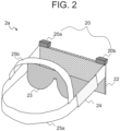
- FIG. 2 illustrates appearance of each of the HMDs 2a, 3a, which are examples of a 3D virtual reality display device.
- the HMD 2a is a video see-through HMD.
- the HMD 3a has the same configuration as that of the HMD 2a, and thus the configuration thereof will not be described herein.
- the HMD 2a includes the ranging camera 20 with parallax and a display 22.
- the HMD 2a takes an image of the foreground using the ranging camera 20, composites the 3D AR object 6 drawn by CG or the like on the image taken by the ranging camera 20, displays the composite image on the display 22 arranged in front of the MR experiencing person 2.
- the ranging camera 20 includes a left camera 20a and a right camera 20b, and measures a distance to an object which is being taken.
- the display 22 is a flat display, and is provided with a shutter 23 inside thereof.
- a left-eye image and a right-eye image are alternately displayed on the display 22, and the shutter 23 is opened and closed in synchronization therewith. That is, when an image for the left eye is displayed, the left half of the display 22 is opened and the right half is closed, and when an image for the right eye is displayed, the left half of the display 22 is closed and the right half is opened.
- This enables 3D display in the HMD 2a.
- the MR experiencing person 2 views the displayed image alternately with only one of the eyes in synchronization with the displayed image.
- the HMD 2a further includes a processor 24 and wearing housings 25a, 25b.
- the HMD 2a is worn to the head via the wearing housings 25a, 25b.
- the display 22 displays a real space image of the front taken by the left camera 20a and right camera 20b, and the MR experiencing person 2 views the displayed real space image. Furthermore, the display 22 displays the 3D AR object 6 superimposed on the real space image. At this time, on the display 22, displaying the image taken by the left camera 20a on which an image of an AR object for the left eye is superimposed and displaying the image taken by the right camera 20b on which an image of an AR object for the right eye is superimposed causes the 3D AR object 6 to be displayed stereographically (three-dimensionally) as if it was at a predetermined distance in the real space.
- the front and rear relation of distances of the real objects of the real space for example, the MR non-experiencing person 4b, vase 5a, and window 5b illustrated in FIG. 1 , and the 3D AR object 6 are reflected.
- the occlusion processing is performed to process the drawing data on the 3D AR object 6 so as to make the portion of the 3D AR object 6 appear hidden by the portion of the real object (MR non-experiencing person 4b).
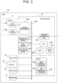
- FIG. 3 is a block diagram of the HMD 2a.
- the components common to those illustrated in FIG. 2 are provided with the same reference signs.
- the processor 24 is surrounded by a broken line, and connected to the left camera 20a, the right camera 20b, the display 22, the shutter 23, a speaker 26, and a microphone 27.
- the processor 24 includes a camera processor 240, an orientation sensor 241, a gyro sensor 242, an acceleration sensor 243, a wireless communication unit 244, a CPU 245 (corresponding to a main processor), a RAM 246, an image RAM 247, a Flash ROM (FROM) 248, and an internal bus 249. These elements above are connected to each other via the internal bus 249.
- the wireless communication unit 244 selects the appropriate processing from among several kinds of communication processing, for example, mobile communication such as 4G and 5G, wireless LAN, and the like, and connects the HMD 2a to the network 7 via the access point 1a.
- mobile communication such as 4G and 5G, wireless LAN, and the like
- the FROM 248 includes a basic program 250 and an MR experience program 251.
- the CPU 245 loads these processing programs onto the RAM 246 and then executes them. Furthermore, the FROM 248 retains data necessary for execution of the processing programs.
- the FROM 248 may be a non-volatile medium other than the Flash ROM.
- the CPU 245 stores image data to be output to the display 22 in the image RAM 247, and then reads out the image data.
- the camera processor 240 executes the processing for calculating a distance to a subject (corresponding to a real object) of the real space image based on the images taken by the left camera 20a and the right camera 20b, and adds, to the real space image, data on the distance to the subject of the real space image.
- the "real space image” refers to only an image, while data to which the distance data is added is referred to as "real space image data”.
- the group of sensors including, for example, the orientation sensor 241, the gyro sensor 242, and the acceleration sensor 243 is used to obtain the position of the HMD 2a and the photographing direction of the ranging camera 20 (used as a line of sight of the MR experiencing person 2 who is wearing the HMD 2a).
- the HMD 2a may include some or all of the processing executed by the VR service server 8 and MR support server 9, which will be described below.
- FIG. 4 is a block diagram of the VR service server 8.
- the VR service server 8 includes a network interface (network IF) 81 for a wired LAN or the like, a CPU 82, a RAM 83, and storage 84, and these are connected to each other via an internal bus 85.
- network IF network interface
- the storage 84 may be the one with which a hard disk drive or the like is combined, other than Flash ROM.
- the storage 84 retains a VR service program 86.
- the CPU 82 loads the VR service program 86 onto the RAM 83 and executes it.
- the storage 84 further retains VR data 87 such as a 3D AR object and the like.
- the VR data 87 is data necessary for execution of the VR service program 86.
- the VR data 87 may also include, in addition to the 3D AR object, VR (Virtual Reality) image data.
- the VR image data is an image used for replacing the entire real space image of the MR experiencing persons 2, 3. Replacement with the VR image data enables the MR experiencing persons 2, 3 to experience observation of the 3D AR object 6 while feeling as if they were in another space given by the VR image data.
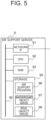
- FIG. 5 is a block diagram of the MR support server 9.
- the MR support server 9 includes a network IF 91 for a wired LAN or the like, a CPU 92, a RAM 93, and a storage 94, which are connected to each other via an internal bus 95.
- the storage 94 may be the one with which a hard disk drive or the like is combined, other than the Flash ROM.
- the storage 94 includes an MR support program 96 as a processing program.
- the CPU 92 loads the MR support program 96 onto the RAM 93 and then executes it.
- the storage 94 further retains a background object image 97 and a real object image 98, which are data necessary for execution of the MR support program 96.
- the background object image 97 and the real object image 98 are data used for an MR experience by a user. In experiencing MR by a plurality of users, data separated for each of the users is provided.
- the real object image 98 is data obtained by detecting an area in which motion is found based on time difference or the like from the real space image received from the HMD 2a and recognizing one grouped area as a real object. Based on the shape of the real object or the like, what the real object is, for example, whether the real object is a person may be detected.
- the background object image 97 is data on a background image obtained by removing an area of the real object from the real space image, and is data on an area where no motion is found in the real space image.
- the background image 97 is on the rear side of the real object image 98, at a certain point in time, that is, in a plurality of same frames (target frame) of the 3D real space image, an image of the background object that is further behind the real object image 98 is not taken.
- the MR support program 96 recognizes the real object image 98 in the target frame and extracts the background object image 97 from the other frames in which the real object is not reflected, thereby generating the background object image 97.
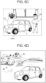
- FIG. 6A to FIG. 6D are diagrams for explaining a 3D virtual reality display method.
- FIG. 6A illustrates an example of the conventional 3D virtual reality display (illustrating an example in which the 3D AR object and the real object are overlapping each other)
- FIG. 6B illustrates the 3D virtual reality display (example of first overlapping elimination display) according to the first embodiment
- FIG. 6C illustrates the 3D virtual reality display (example of second overlapping elimination display) according to the first embodiment
- FIG. 6D illustrates the 3D virtual reality display (example of third overlapping elimination display) according to the first embodiment.
- Each of FIG. 6A to FIG. 6C is illustrated to correspond to the area (AREA) surrounded by a dashed line in FIG. 1 .
- FIG. 1 As illustrated in FIG.
- the MR non-experiencing person 4b that is a real object and the 3D AR object 6 are located at almost the same positions in view of relation of the distances, and are overlapping each other on the line of sight of the HMD 2a.
- the "relation of distances” referred herein is the relation of distances starting from the HMD 2a on the direction same as that of a line-of-sight of the MR experiencing person 2 who is a wearer of the HMD 2a.
- the “relation of distances” does not include relation of distances in the direction different from that of the line-of-sight direction even if the distances from the MR experiencing person 2 are the same.
- FIG. 6A illustrates an image obtained by having performed occlusion between the MR non-experiencing person 4b (real object) and the 3D AR object 6 which are overlapping each other.
- the upper portion of the MR non-experiencing person 4b, which is in front of the 3D AR object 6, is being displayed, however, the lower portion of the MR non-experiencing person 4b, which is behind the 3D AR object 6, is not being displayed.
- occlusion is not executed between the real object (MR non-experiencing person 4b) and the 3D AR object 6 which are at almost the same positions in view of the distances. Instead, a background object image 10 obtained by cutting out from the background image is inserted into the area of the real object (MR non-experiencing person 4b), and occlusion is performed between the background object image 10 and the 3D AR object 6.
- the background object image 10 is located at a distance farther on the same line of sight than the 3D AR object 6, and thus the 3D MR object 6 can be displayed without being lacked, and also a background (for example, the vase 5a) which has been hidden by the real object (MR non-experiencing person 4b) can also be displayed.
- a background for example, the vase 5a
- the real object MR non-experiencing person 4b
- FIG. 6B first overlapping elimination display
- FIG. 6C in addition to FIG. 6B , an image of the real object (MR non-experiencing person 4b) is moved (put off) to a location that does not hinder the recognition of the 3D AR object 6 (second overlapping elimination display).
- An image 11 illustrated in FIG. 6C corresponds to the real object (MR non-experiencing 4b) after being moved.
- a real object is the one who should be paid attention to at all times, for example, a child of the MR experiencing persons 2, 3, the 3D AR object 6 and the real object (MR non-experiencing person 4b) are displayed so as to be visually recognized simultaneously without the real object being hidden, and also the image displayed thereby is not unnatural like the one processed by occlusion. This can maintain the immersive MR experience.
- the distances on the same line of sight from the MR experiencing person 2 may differ such as far or near, and in such a case, reducing or enlarging the scale of the real object (MR non-experiencing person 4b) in accordance with the distances from the MR experiencing person 2 enables visual recognition of the real object in a natural size.
- FIG. 6D illustrates an example of replacing a real space image with VR image data 6a (example of third overlapping elimination display).
- the VR image data 6a is on the back of the 3D AR object 6, the 3D AR object 6 is displayed against the background of the VR image data 6a.
- switching from the video of FIG. 6B or FIG. 6C to the display as illustrated in FIG. 6D enables a video in which various backgrounds and the 3D AR object 6 are combined to be displayed. This allows an experiencing person to visually recognize the 3D AR object 6 in various scenes.
- the video may be gradually composited and varied, or processing such as a wipe may be performed.
- FIG. 7A illustrates a flowchart of the MR experience program 251 according to the first embodiment.
- the MR experiencing person 2 starts the MR experience program 251 stored in the HMD 2a (step S101) and logs-in to the VR service server 8 and the MR support server 9.
- steps S101 operations during execution of the MR experience program 251 by the HMD 2a will be described in order of steps.
- the processing in the case where the MR non-experiencing person 4b as a real object overlaps or does not overlap the 3D AR object 6 of a car will be exemplified.
- the HMD 2a starts taking images (step S102).
- the images taken by the ranging camera 20 are provided with data on a distance to a real object. Taking images may be performed by taking a motion video, for example, at 30fps (frame per second) so as to generate 3D real space image data in which multiple frames are arranged in time series and capturing the image taken thereby.
- the subsequent steps may be performed in synchronization with camera-photographing cycles.
- the HMD 2a transmits 3D real space image data to the MR support server 9 via the wireless communication unit 244 (step S103).
- the MR support server 9 separates an image of a real object (MR non-experiencing person 4b) and an image of a background object (for example, vase 5a, window 5b) from the real space image.
- the HMD 2a transmits, to the VR service server 8, a request to transmit drawing data (included in the VR data 87) on the 3D AR object 6 (step S104).
- the HMD 2a receives, from the MR support server 9, data on at least one or more, preferably all the real object images (including the images of the real object and the distance data thereof) extracted from the real space image (step S105), and receives, from the VR service server 8, the drawing data on the 3D AR object (in the present embodiment, 3D AR object 6) and VR image data (step S106).
- the HMD 2a compares three-dimensional overlapping between each real object (MR non-experiencing person 4b) and the 3D AR object 6, in other words, a distance from the HMD 2a to the real object image (including an image of the MR non-experiencing person 4b and data on a distance thereto) and a distance from the HMD 2a to the 3D AR object 6, starting from the HMD 2a and on the same line of sight.
- the volume of the real object and that of the 3D AR object are overlapping each other.
- the occlusion is successful for the front side of the 3D AR object 6 and the surface of the real object, however, in the depth side of the 3D AR object 6, the occlusion cannot be appropriately processed for the relation of distances with the surface of the real object. This causes unnatural display as if the real object was suddenly appearing from the 3D AR object 6.
- the HMD 2a selects execution of the conventional occlusion processing or overlapping elimination display processing in accordance with the level of the overlapping between the volume of the real object and that of the 3D AR object 6.
- the HMD 2a performs the occlusion processing for the real object and the 3D AR object (step S108) .
- the HMD 2a performs the overlapping elimination display processing.
- FIG. 7B illustrates an exemplary algorithm for determining the level of overlapping of the volumes.
- a display surface of the HMD 2a is assumed to be a surface parallel to the vertical direction. Where one point on the display 22, for example, the upper left corner of the display 22 is set as an origin, 3D coordinates of reality are defined using the x-y plane of 2D coordinates of the screen and the z-axis orthogonal thereto.
- the z-x plane is the horizontal plane and the z-axis represents a distance in the depth direction of the line of sight as viewed from the HMD 2a.
- a value of the z-axis corresponds to a distance from the HMD 2a to the MR non-experiencing person 4b. Since the MR non-experiencing person 4b is visually recognized using the ranging camera 20, a position P R (x R , z R ) of the MR non-experiencing person 4b on a line of sight L from an observer can be expressed by an intersection point between a surface of the MR non-experiencing person 4b which faces the HMD 2a and the line of sight L.
- the shape of the 3D AR object 6 is assumed to be defined using three-axes coordinates of (s, t, u) of a 3D image system.
- the 3D AR object 6 Upon appearance of an AR marker in the real space, the 3D AR object 6 is superimposed thereon and displayed.
- the origin (s 0 , t 0 , u 0 ) of the 3D AR object 6 is superimposed on 3D coordinates (x l , y m , z n ) of the AR marker, (s 0 , t 0 , u 0 ) can be converted into (x l , y m , z n ).
- the processor 24 selects the point as a farthest point P n , while if there is a plurality of points such as P 1 , ..., P n-2 , P n-1 , P n , the processor 24 selects, as the farthest point P n , a point farthest from the HMD 2a, that is, a point having the largest z-axis value. Note that a point P 1 having the smallest z-axis value is the closest point.
- z R >z ARn the processor 24 determines that there is no overlapping of the volumes between the real object and the 3D AR object 6 (State 1).
- z R ⁇ z ARn the processor 24 determines that there is overlapping of the volumes between the real object and the 3D AR object 6 (State 2).
- the HMD 2a makes a request of transmission of data about a background object image (corresponding to the background object image 10 in FIG. 6B ) corresponding to an area of the real object (MR non-experiencing person 4b) to the MR support server 9 (step S109), and receives the data (step S110).
- the HMD 2a hides the real object (MR non-experiencing person 4b) with the background object image 10 and the 3D AR object 6 (first overlapping elimination display).
- the HMD 2a cuts out the real object (MR non-experiencing person 4b) and displays it at a location that does not overlap the 3D AR object 6, and inserts the background object image 10 into the area where the real object (MR non-experiencing person 4b) is actually present (second overlapping elimination display).
- the HMD 2a replaces the background object image within the real object with the VR image in steps S107 and S108, and performs the occlusion processing for the VR image of the background, the 3D AR object, and the real object, and the composition processing such as moving the real object.
- the HMD 2a performs the processing of compositing the images displayed on the HMD 2a, however, a subject of performing the composition processing is not limited thereto, and a server connected via a network, a smart phone or tablet linked and connected, or the like, as will be described later, may perform the processing.
- the HMD 2a confirms whether the steps S107 to Sill have been performed for all the real objects that overlap the 3D AR object 6, and if any real object remains unprocessed, the HMD 2a returns to step S107 (step S112: No). On the other hand, if all the real objects have been already processed (step S112: Yes), the HMD 2a displays the processed images on the display 22 of the HMD 2a (step S113) .
- step S114: No the HMD 2a ends the processing above.
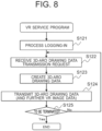
- FIG. 8 illustrates a flowchart of the VR service program 86.
- the VR service server 8 Upon receiving the log-in request from the registered MR experiencing person 2, the VR service server 8 executes log-in processing (step S121).
- the VR service server 8 Upon receiving the request to transmit the drawing data on the 3D AR object 6 from the HMD 2a (step S122), the VR service server 8 creates the requested drawing data on the 3D AR object (step S123).
- the drawing data on the 3D AR object is data (object file) obtained by three-dimensionally drawing the 3D AR object 6 in accordance with, for example, the distance between the HMD 2a and the 3D AR object and the line-of-sight direction of the HMD 2a, which are included in the transmission request of the drawing data on the 3D AR object.
- the drawing data is updated as the HMD 2a moves and the line-of-sight changes.
- the drawing data may additionally include, as images, influences of reflection and shadows based on a direction of a light source such as the sun or illumination.
- the VR service server 8 transmits the created drawing data to the HMD 2a (step S124).
- the VR service server 8 continues the processes from steps S122 to S124 until a termination condition of the VR service program 86, for example, logging-out by the MR experiencing person 2 or termination of the MR experience program 251, is satisfied (step S125: No).
- step S125: Yes Upon satisfaction of the termination condition of the VR service program 86 (step S125: Yes), the VR service server 8 ends the series of processes described above.
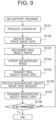
- FIG. 9 illustrates a flowchart of the MR support program 96.
- the MR support server 9 processes the log-in request from the registered MR experiencing person 2 (step S131).
- the MR support server 9 receives the real space image data from the HMD 2a (step S132), recognizes the real object image (step S133), extracts the real object image data, and obtains the background image.
- the MR support server 9 updates the background image each time it receives a real space image (step S134).
- the MR support server 9 transmits the real object image data to the HMD 2a (step S135). Upon receiving the request to transmit the background object image (step S136), the MR support server 9 transmits the background object image data to the HMD 2a (step S137).
- the MR support server 9 continues the processes from steps S132 to S137 until a termination condition of the MR support program 96, for example, logging-out by the MR experiencing person 2 or termination of the MR experience program 251, is satisfied (step S138: No).
- the MR support server 9 Upon satisfaction of the termination condition of the MR support program 96 (step S138: Yes), the MR support server 9 ends the series of processes.
- the occlusion is performed while, when the real object and the 3D AR object 6 are so close to each other that they overlap each other, the overlapping elimination processing is performed without occlusion.
- This can prevent the real object and the 3D AR object 6 from being displayed with unnaturally overlapping each other, and thus can realize enhancement of the immersive experience of MR.
- FIG. 10A illustrates the conventional 3D virtual reality display (illustrating a state in which a real object is in front of the 3D AR object 6).
- FIG. 10B illustrates the 3D virtual reality display (fourth overlapping elimination display) according to the second embodiment.
- the MR non-experiencing person 4b that is a real object and the 3D AR object 6 are at almost the same positions at the same distance.
- another MR non-experiencing person 4c that is a real object is in front of the 3D AR object 6. Both of them overlap the 3D AR object 6 from the line of sight of the HMD 2a, and thus hinder the observation of the 3D AR object 6.
- the MR non-experiencing person 4b behind the 3D AR object 6 is replaced with the background object image 10.
- the other MR non-experiencing person 4c is deleted such that the 3D AR object 6 is arranged. Furthermore, within an area where the MR non-experiencing person 4c has been deleted, in a remaining area where the 3D AR object 6 does not overlap, a foreground image, which has been generated by extracting an image corresponding to the remaining area from the images of the overall view in other frames is embedded.
- the 3D AR object 6 and the background object image 10 correspond to the MR non-experiencing person 4b
- the 3D AR object 6 and a foreground image 11a correspond to the other MR non-experiencing person 4c.
- the processing of overwriting and hiding the real object images of the MR non-experiencing person 4b and other MR non-experiencing person 4c is performed (example of fourth overlapping elimination display). This enables the entire 3D AR object 6 to be observed.
- FIG. 11 illustrates a flowchart of the MR experience program 251 according to the second embodiment.
- the flowchart illustrated in FIG. 11 is different from the flowchart illustrated in FIG. 7 in distance comparison in step S150.
- step S150 whether the distance between a real object and the 3D AR object 6 falls within a case of "being on rear and apart” or a case of “being close or on front” is determined, and in the former case, occlusion is performed between the real object and the 3D AR object 6 (step S108), and in the latter case, a request to transmit the background object image and the foreground image is made (step S151) to receive the data (step S152). Then, the real object image is hidden with the background object image, the 3D AR object 6, and the foreground image (step S153). In the example above, the processing of displaying as if the MR non-experiencing person 4b and the other non-experiencing person 4c were not there is performed.
- the same features as those of the first embodiment are provided, and also, even if a real object is in front of the 3D AR object 6, it is possible to remove the real object that interferes observation of the 3D AR object 6.
- FIG. 12A illustrates the conventional 3D virtual reality display (illustrating a state in which the 3D AR objects and the real object are overlapping each other).
- FIG. 12B illustrates an example of the 3D virtual reality display according to a third embodiment (example of processing a transparent part).
- FIG. 12C illustrates an example of the 3D virtual reality display according to the third embodiment (example of replacement with a VR image).
- the MR experiencing person 2 is experiencing a situation as if he or she was sitting in a driver's seat.
- a dashboard 60, a front window 61, a rearview mirror 62, a steering wheel 63, and the like are being displayed.
- the MR non-experiencing persons 4d, 4e overlap the front window 61 and are visible through the front window 61.
- the dashboard 60, the front window 61, the rearview mirror 62, and the steering wheel 63 are components of the 3D AR object 6 of a car.
- the 3D AR object 6, which is one virtual reality object is divided into a plurality of parts of the virtual reality object, and a flag for defining the type of occlusion is added to each of the parts.
- Each of the dashboard 60, the rearview mirror 62, and the handle 63, which is a non-transparent area of the 3D AR object 6, is provided with a non-transparent area flag.
- the front window 61, which is a transparent area of the 3D AR object 6, is provided with a transparent area flag.
- FIG. 12A occlusion has not been performed, and thus the MR non-experiencing persons 4d, 4e appear unnaturally overlapping the 3D AR object 6.
- FIG. 12B illustrates the state after occlusion has been performed.
- an Occlusion Flag which will be described in FIG. 13 is set for the drawing data on the 3D AR object 6 of the front window 61, and thus the processing of replacing the real object overlapping the front window 61 with the 3D AR object 6 is prohibited while occlusion is performed between the real object and the 3D AR object 6. This allows the MR non-experiencing persons 4d, 4e to be observed through the front window 61.
- the MR non-experiencing person 4e is farther than the dashboard (3D AR object) 60, the steering wheel 63(3D AR object), and also the 3D AR object 6 that is the vehicle body, and thus is processed with occlusion based on the relation of distances to the components above other than the front window 61 which is treated as being transparent.
- FIG. 12C illustrates the case where the background image of the real space is replaced with a VR image 6b.
- the dashboard 60, the steering wheel 63, and the VR image 6b are processed by occlusion.
- the front window 61 is a transparent or semi-transparent 3D AR object through which the VR image 6b at the back of the line of sight can be observed. This can realize an experience as if an experiencing person was in a virtual location provided by the VR image.
- FIG. 13 illustrates an exemplary table 100 of the 3D AR objects.
- the 3D AR objects are identified by a "CONTENTS ID", and a plurality of 3D AR objects (such as AR Object 1 to 7) can be grouped together as being related to each other.
- Each of the 3D AR objects includes, in addition to a "Data id” specific to each of the 3D AR objects, and a “Title” for helping users such as MR experiencing persons to grasp them, the "Occlusion Flag" and "3D Image Data”.
- the "Occlusion Flag” defines “00", "01", and "10". When the value of the "Occlusion Flag” is "00", occlusion is performed in accordance with the distances of the real object and 3D AR object. A flag with the "Occlusion Flag” of "00" corresponds to a non-transparent part flag.
- the 3D AR object is treated as being transparent regardless of the distance, and occlusion is performed between the 3D AR object ahead of the front window 61 and the real object.
- a flag with the "Occlusion Flag" of "10" corresponds to a transparent part flag.
- the 3D AR object ahead of the front window 61 may be a portion of the 3D AR object 6 of the car such as a hood, or may be another 3D AR object different from the 3D AR object 6 of the car such as a 3D AR object of another car.
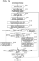
- FIG. 14 illustrates a flowchart of the MR experience program 251 according to the third embodiment.
- the flowchart illustrated in FIG. 14 is different from the flowchart illustrated in FIG. 7 in steps S160 and S161 which have been added.
- step S160 the HMD 2a checks the "Occlusion Flag" of the 3D AR object, so as to, as described with reference to FIG. 13 , make the processing differ depending on the values of the "Occlusion Flag".
- the HMD 2a performs occlusion in accordance with the relation of the distances of the real object and 3D AR object in step S108. (This processing will be described with reference to FIG. 15 .)
- step S161 the HMD 2a treats the AR object as a transparent object like the front window 61 illustrated in FIG. 12 , and performs the processing of making the AR object appear transparent even if it is closer than the real object. Thereafter, the processing enters step S107.
- the HMD 2a compares the distances of the real object and 3D AR object in step S107, and makes the processing different between the case of being apart and the case being close or overlapping.
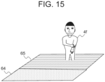
- FIG. 15 illustrates an exemplary image in the case of the "Occlusion Flag" of "00".
- FIG. 15 illustrates a situation in which a real object 4f is playing at the seaside (including 3D AR objects of a sand beach 64 and sea surface 65).
- the "Occlusion Flag" of the sea surface 65 is set to "00".
- a person who is the real object 4f is appearing only by half from the sea surface 65, but this does not cause unnaturalness. Accordingly, occlusion may be performed based on the relation of the distances of the sea surface 65 and real object 4f.
- the same features as those of the first embodiment are provided, and also, it is possible to apply occlusion in accordance with the characteristics of 3D AR objects.
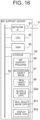
- FIG. 16 is a block diagram of the MR support server 9 according to the fourth embodiment.
- the MR support server 9 according to the fourth embodiment holds 3D AR object & VR image data 900, real space image data 901, and display image data 902 in the storage 94.
- the MR support server 9 Based on an instruction from the HMD 2a, the MR support server 9 according to the fourth embodiment holds the 3D AR object & VR image data 900 received from the VR service server 8 and the real space image data 901 received from the HMD 2a.
- the MR support server 9 recognizes and extracts an object located, in the depth direction on the line of sight, on the deeper side (farther side) from the real object image 98 as a background object from the real space image data 901, so as to generate the background object image 97.
- the MR support server 9 performs occlusion and the like between the real object image 98 and the 3D AR object & VR image data 900 to obtain the display image data 902 obtained by compositing the data above with the real space image.
- the MR support server 9 transmits the display image data 902 to the HMD 2a, and the HMD 2a displays the display image data 902 on the display 22.
- the MR support server 9 stores it in the 3D AR object & VR image data 900.
- the MR support server 9 includes a program for replacing the background image within the real object with the VR image data, performing occlusion for the VR image of the background, the 3D AR object, and the real object, and performing composition such as moving the real object.
- FIG. 17 illustrates a flowchart of the MR support program 96 according to the fourth embodiment.
- the MR support server 9 processes the log-in request from the registered MR experiencing person 2 (step S131). Furthermore, the MR support server 9 receives the real space image data from the HMD 2a (step S132).
- the MR support server 9 transmits, to the VR service server, the request to transmit the drawing data on the 3D AR object (step S140).
- a user of the HMD 2a decides which AR content to be composited, and the MR support server 9 receives an instruction to transmit the drawing data about the 3D AR object based on the decision above.
- the MR support server 9 recognizes the real object from the real space image data received in step S132 (step S133), and updates the background image based on the real space image data as received (step S134).
- the MR support server 9 receives the drawing data about the 3D AR object and the VR image (may not receive the VR image) data (step S141).
- the MR support server 9 detects the overlapping between the real object and the 3D AR object, and also compares the distances of the two objects (step S142). When they are so apart that the volumes thereof are not overlapping each other (step S142: being apart), the MR support server 9 performs occlusion between the real object and the 3D AR object (step S143).
- the MR support server 9 when they are overlapping each other (step S142: overlapping), the MR support server 9 generates the data on the background object image based on the background image (step S144), and performs the processing for overwriting and hiding the real object with the background object image and the 3D AR object (step S145) .
- the MR support server 9 confirms whether the processes in steps from S142 to S145 have been executed for all the real objects overlapping the 3D AR object, and returns to step S142 if any real object remains unprocessed (step S146: No).
- the MR support server 9 Upon completion of processes for all the real objects (step S146: Yes), the MR support server 9 transmits the processed images to the HMD 2a as the display image data (step S147) .
- the MR support server 9 confirms whether the program is to be terminated. If the program is not to be terminated (step S138: No), the MR support server 9 continues the steps from step S142. If the program is to be terminated (step S138: Yes), the MR support server 9 ends the series of processes.
- the same features as those of the first embodiment are provided, and also, it is possible to make the implementation flexible by, for example, realizing execution of the most of the MR experience processing by the high-performance MR support server 9 so as to reduce the processing load on the HMD 2a.
- the present invention is not limited to the embodiments illustrated in FIG. 1 to FIG. 17 , but allows a part of the configuration of one embodiment to be replaced with a part of other embodiments. Furthermore, configurations of other embodiments may be added to configurations of a certain embodiment. All of these are included in the scope of the present invention.
- the numerical values and messages appearing in the text and drawings are merely examples, and thus the advantageous effects of the present invention are not impaired even if different ones are used.
Landscapes
- Engineering & Computer Science (AREA)
- Physics & Mathematics (AREA)
- Theoretical Computer Science (AREA)
- General Physics & Mathematics (AREA)
- General Engineering & Computer Science (AREA)
- Computer Graphics (AREA)
- Software Systems (AREA)
- Computer Hardware Design (AREA)
- Geometry (AREA)
- Architecture (AREA)
- Human Computer Interaction (AREA)
- Processing Or Creating Images (AREA)
- User Interface Of Digital Computer (AREA)
Abstract
Description
- The present invention relates to a 3D virtual reality display device, a head-mounted display, and a 3D virtual reality display method, and more particularly, to a technology used for experiencing Mixed Reality (MR) including a real space and a virtual reality object (AR object: Argument Reality Object).
-
Patent Literature 1 discloses a technique in which "an information processing device that outputs a composite image obtained by compositing a real space image and a virtual object image to a display device identifies a position of a real object, determines whether the real object is moving based on information on the identified position of the real object, and outputs the composite image so as to cause the display device to display the composite image in a manner allowing the presence or absence of the real object to be recognized when the real object is moving (excerpted from Abstract)". - Patent Literature 1:
JP-A-2016-122392 - In
Patent Literature 1, in the case where a 3D AR object and a real object of a real space overlap each other on a line of sight from an HMD, the appearance of displaying the 3D AR object is restricted, for example, by causing the 3D AR object to be displayed semi-transparently or not displaying the 3D AR object near the real object. This may cause difficulty in accurately recognizing the 3D AR object and experiencing MR. - The present invention has been made in view of the problem above, and an object of the present invention is to provide a technology capable of realizing more accurate recognition of a 3D AR object.
- In order to solve the problem above, the present invention includes the features recited in the scope of claims. One of the aspects thereof is a 3D virtual reality display device, comprising: a camera that takes an image of a real space and outputs a real object image of a real object included in the real space; a distance sensor that measures a distance from an observer of the real space to the real object; a display; and a processor that displays a 3D virtual reality object on the display; the processor being configured to: when the real object is on a line of sight of the observer who is observing the 3D virtual reality object, compare a distance from the observer to a position at which the 3D virtual reality object is being displayed with a distance from the observer to the real object; and when the real object is overlapping the 3D virtual reality object, perform overlapping elimination display processing of displaying the 3D virtual reality object on the line of sight while not displaying the real object image on the line of sight.
- According to the present invention, it is possible to realize more accurate recognition of a 3D AR object. The problems, configurations, and advantageous effects other than those described above will be clarified by explanation of the embodiments below.
-
- [
FIG. 1] FIG. 1 is a schematic diagram of a 3D virtual reality display system according to a first embodiment. - [
FIG. 2] FIG. 2 illustrates appearance of an HMD which is an example of a 3D virtual reality display device. - [
FIG. 3] FIG. 3 is a block diagram of an HMD. - [
FIG. 4] FIG. 4 is a block diagram of a VR service server. - [
FIG. 5] FIG. 5 is a block diagram of an MR support server. - [
FIG. 6A] FIG. 6A illustrates an example of conventional 3D virtual reality display (illustrating a state in which a 3D AR object and a real object are overlapping each other). - [
FIG. 6B] FIG. 6B illustrates 3D virtual reality display (example of first overlapping elimination display) according to the first embodiment. - [
FIG. 6C] FIG. 6C illustrates 3D virtual reality display (example of second overlapping elimination display) according to the first embodiment. - [
FIG. 6D] FIG. 6D illustrates 3D virtual reality display (example of third overlapping elimination display) according to the first embodiment. - [
FIG. 7A] FIG. 7A illustrates a flowchart of an MR experience program according to the first embodiment. - [
FIG. 7B] FIG. 7B illustrates an example of a determination algorithm for the level of overlapping of volumes. - [
FIG. 8] FIG. 8 illustrates a flowchart of a VR service server according to the first embodiment. - [
FIG. 9] FIG. 9 illustrates a flowchart of an MR support server according to the first embodiment. - [
FIG. 10A] FIG. 10A illustrates an example of conventional 3D virtual reality display (illustrating a state in which a real object is in front of a 3D AR object). - [
FIG. 10B] FIG. 10B illustrates 3D virtual reality display (example of fourth overlapping elimination display) according to a second embodiment. - [
FIG. 11] FIG. 11 illustrates a flowchart of an MR experience program according to the second embodiment. - [
FIG. 12A] FIG. 12A illustrates an example of conventional 3D virtual reality display (illustrating a state in which a 3D AR object and a real object are overlapping each other). - [
FIG. 12B] FIG. 12B illustrates an example of 3D virtual reality display (example of processing a transparent part) according to a third embodiment. - [
FIG. 12C] FIG. 12C illustrates an example of 3D virtual reality display (example of replacement with a VR image) according to the third embodiment. - [
FIG. 13] FIG. 13 illustrates a 3D AR object table. - [
FIG. 14] FIG. 14 illustrates a flowchart of an MR experience program according to the third embodiment. - [
FIG. 15] FIG. 15 illustrates another example of 3D virtual reality display according to the third embodiment. - [
FIG. 16] FIG. 16 is a block diagram of an MR support server according to a fourth embodiment. - [
FIG. 17] FIG. 17 illustrates a flowchart of 3D virtual reality display processing according to the fourth embodiment. - Hereinafter, embodiments of the present invention will be described with reference to the drawings. Throughout all the drawings, the common elements and steps are provided with the same reference signs, and are not described in detailed repetitively.
- In the present embodiment, a 3D virtual reality object (hereinafter, referred to as a "3D AR object", and in the drawings, referred to as a "3D-ARO") created by computer graphics (CG) is composited on a 3D real space image (hereinafter, referred to as a "real space image") obtained by taking images of a real space using a ranging camera, and the image thus composited is displayed. In the present embodiment, a camera and a distance sensor for measuring a distance are integrally configured by using a ranging
camera 20, however the camera and a separate distance sensor such as an ultrasonic range finder may be combined and used. - In superimposing a 3D AR object on a 3D real space image obtained by taking an image of a real space and displaying the image thus composited, an image to be displayed far from a viewpoint has a shielded area due to an image to be displayed close to the viewpoint. As an image processing method for expressing the shielded area, occlusion has been known.
- An image of a mixed reality (MR) space obtained by compositing an AR image on an image of a background of a real space is used for contents such as games, maintenance work, and sales promotion. For compositing an AR image, for example, an image of a subject called an AR marker is taken based on the real space image, and then an AR image associated with the AR marker is superimposed on an area of the subject. There are often the cases that, as hardware for displaying 3D virtual reality, an HMD (head-mounted display) integrating a camera and a display is used, and accordingly, hereinafter, an embodiment for implementing the present invention in HMDs will be described.
- A first embodiment will be described with reference to
FIG. 1 to FIG. 9 . -
FIG. 1 is a schematic diagram of a 3D virtual reality display system according to the first embodiment. -
FIG. 1 illustrates that anMR experiencing person 2 is wearing anHMD 2a on the head and viewing anMR space 1. Similarly, anMR experiencing person 3 is wearing anHMD 3a on the head and viewing theMR space 1. - The
HMDs access point 1a so as to be connected thereto, respectively, and establish wireless communication. - The
access point 1a is placed in theMR space 1, and connected to anetwork 7 outside theMR space 1 so as to cause theHMDs VR service server 8 andMR support server 9 located on thenetwork 7, respectively. Here, VR (Virtual Reality) means a virtual reality space. - The real space includes MR
non-experiencing persons vase 5a and awindow 5b as portions of the background of the real space. A3D AR object 6 is a 3D AR object of a car. - The
MR space 1 is a space intended to be used for sales promotion of cars. TheMR space 1 is not limited for use by one particular MR experiencing person, but may provide a plurality of persons, such as theMR experiencing persons MR experiencing person 3 may be a promoter who is explaining a product while observing the same3D AR object 6 that theMR experiencing person 2 is also observing from a different orientation, or may be another visitor who is observing a 3D AR object different from the3D AR object 6 that theMR experiencing person 2 is observing. The promoter has only to present a car to be sold as the3D AR object 6, but does not have to display an expensive real object (car), nor prepare a large space for displaying a plurality of cars. In addition to theMR experiencing persons MR space 1 may include visitors such as MRnon-experiencing persons non-experiencing persons MR experiencing persons - The MR
non-experiencing persons 3D AR object 6, and can freely move in theMR space 1. This may cause a situation in which, for example, the MRnon-experiencing person 4b is at the same position of the3D AR object 6. -
FIG. 2 illustrates appearance of each of theHMDs HMD 2a is a video see-through HMD. TheHMD 3a has the same configuration as that of theHMD 2a, and thus the configuration thereof will not be described herein. TheHMD 2a includes the rangingcamera 20 with parallax and adisplay 22. TheHMD 2a takes an image of the foreground using the rangingcamera 20, composites the3D AR object 6 drawn by CG or the like on the image taken by the rangingcamera 20, displays the composite image on thedisplay 22 arranged in front of theMR experiencing person 2. - The ranging
camera 20 includes aleft camera 20a and aright camera 20b, and measures a distance to an object which is being taken. Thedisplay 22 is a flat display, and is provided with ashutter 23 inside thereof. A left-eye image and a right-eye image are alternately displayed on thedisplay 22, and theshutter 23 is opened and closed in synchronization therewith. That is, when an image for the left eye is displayed, the left half of thedisplay 22 is opened and the right half is closed, and when an image for the right eye is displayed, the left half of thedisplay 22 is closed and the right half is opened. This enables 3D display in theHMD 2a. TheMR experiencing person 2 views the displayed image alternately with only one of the eyes in synchronization with the displayed image. - The
HMD 2a further includes aprocessor 24 and wearinghousings HMD 2a is worn to the head via the wearinghousings - The
display 22 displays a real space image of the front taken by theleft camera 20a andright camera 20b, and theMR experiencing person 2 views the displayed real space image. Furthermore, thedisplay 22 displays the3D AR object 6 superimposed on the real space image. At this time, on thedisplay 22, displaying the image taken by theleft camera 20a on which an image of an AR object for the left eye is superimposed and displaying the image taken by theright camera 20b on which an image of an AR object for the right eye is superimposed causes the3D AR object 6 to be displayed stereographically (three-dimensionally) as if it was at a predetermined distance in the real space. - In displaying by the
HMD 2a, the front and rear relation of distances of the real objects of the real space, for example, the MRnon-experiencing person 4b,vase 5a, andwindow 5b illustrated inFIG. 1 , and the3D AR object 6 are reflected. For example, in the relation in which a portion of a real object (MRnon-experiencing person 4b) is in front of a portion of the3D AR object 6, the occlusion processing is performed to process the drawing data on the3D AR object 6 so as to make the portion of the3D AR object 6 appear hidden by the portion of the real object (MRnon-experiencing person 4b). -
FIG. 3 is a block diagram of theHMD 2a. InFIG. 3 , the components common to those illustrated inFIG. 2 are provided with the same reference signs. InFIG. 3 , theprocessor 24 is surrounded by a broken line, and connected to theleft camera 20a, theright camera 20b, thedisplay 22, theshutter 23, aspeaker 26, and amicrophone 27. - The
processor 24 includes acamera processor 240, anorientation sensor 241, agyro sensor 242, anacceleration sensor 243, awireless communication unit 244, a CPU 245 (corresponding to a main processor), aRAM 246, animage RAM 247, a Flash ROM (FROM) 248, and aninternal bus 249. These elements above are connected to each other via theinternal bus 249. - The
wireless communication unit 244 selects the appropriate processing from among several kinds of communication processing, for example, mobile communication such as 4G and 5G, wireless LAN, and the like, and connects theHMD 2a to thenetwork 7 via theaccess point 1a. - The FROM 248 includes a
basic program 250 and anMR experience program 251. TheCPU 245 loads these processing programs onto theRAM 246 and then executes them. Furthermore, the FROM 248 retains data necessary for execution of the processing programs. The FROM 248 may be a non-volatile medium other than the Flash ROM. - The
CPU 245 stores image data to be output to thedisplay 22 in theimage RAM 247, and then reads out the image data. - The
camera processor 240 executes the processing for calculating a distance to a subject (corresponding to a real object) of the real space image based on the images taken by theleft camera 20a and theright camera 20b, and adds, to the real space image, data on the distance to the subject of the real space image. In the present description, the "real space image" refers to only an image, while data to which the distance data is added is referred to as "real space image data". - The group of sensors including, for example, the
orientation sensor 241, thegyro sensor 242, and theacceleration sensor 243 is used to obtain the position of theHMD 2a and the photographing direction of the ranging camera 20 (used as a line of sight of theMR experiencing person 2 who is wearing theHMD 2a). - The
HMD 2a may include some or all of the processing executed by theVR service server 8 andMR support server 9, which will be described below. -
FIG. 4 is a block diagram of theVR service server 8. TheVR service server 8 includes a network interface (network IF) 81 for a wired LAN or the like, aCPU 82, aRAM 83, andstorage 84, and these are connected to each other via aninternal bus 85. - The
storage 84 may be the one with which a hard disk drive or the like is combined, other than Flash ROM. Thestorage 84 retains aVR service program 86. TheCPU 82 loads theVR service program 86 onto theRAM 83 and executes it. - The
storage 84 further retainsVR data 87 such as a 3D AR object and the like. TheVR data 87 is data necessary for execution of theVR service program 86. - The
VR data 87 may also include, in addition to the 3D AR object, VR (Virtual Reality) image data. The VR image data is an image used for replacing the entire real space image of theMR experiencing persons MR experiencing persons 3D AR object 6 while feeling as if they were in another space given by the VR image data. -
FIG. 5 is a block diagram of theMR support server 9. TheMR support server 9 includes a network IF 91 for a wired LAN or the like, aCPU 92, aRAM 93, and astorage 94, which are connected to each other via aninternal bus 95. - The
storage 94 may be the one with which a hard disk drive or the like is combined, other than the Flash ROM. Thestorage 94 includes anMR support program 96 as a processing program. TheCPU 92 loads theMR support program 96 onto theRAM 93 and then executes it. - The
storage 94 further retains abackground object image 97 and areal object image 98, which are data necessary for execution of theMR support program 96. - The
background object image 97 and thereal object image 98 are data used for an MR experience by a user. In experiencing MR by a plurality of users, data separated for each of the users is provided. - The
real object image 98 is data obtained by detecting an area in which motion is found based on time difference or the like from the real space image received from theHMD 2a and recognizing one grouped area as a real object. Based on the shape of the real object or the like, what the real object is, for example, whether the real object is a person may be detected. - The
background object image 97 is data on a background image obtained by removing an area of the real object from the real space image, and is data on an area where no motion is found in the real space image. In the area of the real object which has been removed, among the real space images obtained back in time, data when the real object has not appearred in the area is interpolated, whereby the background image is obtained. More specifically, since thebackground object image 97 is on the rear side of thereal object image 98, at a certain point in time, that is, in a plurality of same frames (target frame) of the 3D real space image, an image of the background object that is further behind thereal object image 98 is not taken. TheMR support program 96 recognizes thereal object image 98 in the target frame and extracts thebackground object image 97 from the other frames in which the real object is not reflected, thereby generating thebackground object image 97. -
FIG. 6A to FIG. 6D are diagrams for explaining a 3D virtual reality display method.FIG. 6A illustrates an example of the conventional 3D virtual reality display (illustrating an example in which the 3D AR object and the real object are overlapping each other),FIG. 6B illustrates the 3D virtual reality display (example of first overlapping elimination display) according to the first embodiment,FIG. 6C illustrates the 3D virtual reality display (example of second overlapping elimination display) according to the first embodiment, andFIG. 6D illustrates the 3D virtual reality display (example of third overlapping elimination display) according to the first embodiment. Each ofFIG. 6A to FIG. 6C is illustrated to correspond to the area (AREA) surrounded by a dashed line inFIG. 1 . As illustrated inFIG. 1 , the MRnon-experiencing person 4b that is a real object and the3D AR object 6 are located at almost the same positions in view of relation of the distances, and are overlapping each other on the line of sight of theHMD 2a. The "relation of distances" referred herein is the relation of distances starting from theHMD 2a on the direction same as that of a line-of-sight of theMR experiencing person 2 who is a wearer of theHMD 2a. The "relation of distances" does not include relation of distances in the direction different from that of the line-of-sight direction even if the distances from theMR experiencing person 2 are the same. -
FIG. 6A illustrates an image obtained by having performed occlusion between the MRnon-experiencing person 4b (real object) and the3D AR object 6 which are overlapping each other. The upper portion of the MRnon-experiencing person 4b, which is in front of the3D AR object 6, is being displayed, however, the lower portion of the MRnon-experiencing person 4b, which is behind the3D AR object 6, is not being displayed. This results in an unnatural image in which thenon-experiencing person 4b is appearing from the 3D AR object 6 (as if the person's upper body was on the hood of the car or growing therefrom), and thus causes the presence of the MRnon-experiencing person 4b to hinder the recognition of the3D AR object 6. For avoiding such unnaturalness, in the present embodiment, the processing illustrated inFIG. 6B orFIG. 6C is performed. - In
FIG. 6B andFIG. 6C , occlusion is not executed between the real object (MRnon-experiencing person 4b) and the3D AR object 6 which are at almost the same positions in view of the distances. Instead, abackground object image 10 obtained by cutting out from the background image is inserted into the area of the real object (MRnon-experiencing person 4b), and occlusion is performed between thebackground object image 10 and the3D AR object 6. In normal cases, thebackground object image 10 is located at a distance farther on the same line of sight than the3D AR object 6, and thus the3D MR object 6 can be displayed without being lacked, and also a background (for example, thevase 5a) which has been hidden by the real object (MRnon-experiencing person 4b) can also be displayed. This can realize a natural MR experience. The above is the processing illustrated inFIG. 6B (first overlapping elimination display). - In
FIG. 6C , in addition toFIG. 6B , an image of the real object (MRnon-experiencing person 4b) is moved (put off) to a location that does not hinder the recognition of the 3D AR object 6 (second overlapping elimination display). Animage 11 illustrated inFIG. 6C corresponds to the real object (MR non-experiencing 4b) after being moved. According to this processing, in the case where a real object (MRnon-experiencing person 4b) is the one who should be paid attention to at all times, for example, a child of theMR experiencing persons 3D AR object 6 and the real object (MRnon-experiencing person 4b) are displayed so as to be visually recognized simultaneously without the real object being hidden, and also the image displayed thereby is not unnatural like the one processed by occlusion. This can maintain the immersive MR experience. Here, when moving the real object (MRnon-experiencing person 4b), the distances on the same line of sight from theMR experiencing person 2 may differ such as far or near, and in such a case, reducing or enlarging the scale of the real object (MRnon-experiencing person 4b) in accordance with the distances from theMR experiencing person 2 enables visual recognition of the real object in a natural size. -
FIG. 6D illustrates an example of replacing a real space image withVR image data 6a (example of third overlapping elimination display). In the case where theVR image data 6a is on the back of the3D AR object 6, the3D AR object 6 is displayed against the background of theVR image data 6a. Depending on the situations of car sales promotion, switching from the video ofFIG. 6B orFIG. 6C to the display as illustrated inFIG. 6D enables a video in which various backgrounds and the3D AR object 6 are combined to be displayed. This allows an experiencing person to visually recognize the3D AR object 6 in various scenes. In switching from the video ofFIG. 6B orFIG. 6C to the background video ofFIG. 6D , the video may be gradually composited and varied, or processing such as a wipe may be performed. -
FIG. 7A illustrates a flowchart of theMR experience program 251 according to the first embodiment. TheMR experiencing person 2 starts theMR experience program 251 stored in theHMD 2a (step S101) and logs-in to theVR service server 8 and theMR support server 9. Hereinafter, operations during execution of theMR experience program 251 by theHMD 2a will be described in order of steps. In the following, the processing in the case where the MRnon-experiencing person 4b as a real object overlaps or does not overlap the3D AR object 6 of a car will be exemplified. - The
HMD 2a starts taking images (step S102). The images taken by the rangingcamera 20 are provided with data on a distance to a real object. Taking images may be performed by taking a motion video, for example, at 30fps (frame per second) so as to generate 3D real space image data in which multiple frames are arranged in time series and capturing the image taken thereby. The subsequent steps may be performed in synchronization with camera-photographing cycles. - The
HMD 2a transmits 3D real space image data to theMR support server 9 via the wireless communication unit 244 (step S103). As will be described later, theMR support server 9 separates an image of a real object (MRnon-experiencing person 4b) and an image of a background object (for example,vase 5a,window 5b) from the real space image. - Furthermore, the
HMD 2a transmits, to theVR service server 8, a request to transmit drawing data (included in the VR data 87) on the 3D AR object 6 (step S104). - The
HMD 2a receives, from theMR support server 9, data on at least one or more, preferably all the real object images (including the images of the real object and the distance data thereof) extracted from the real space image (step S105), and receives, from theVR service server 8, the drawing data on the 3D AR object (in the present embodiment, 3D AR object 6) and VR image data (step S106). - The
HMD 2a compares three-dimensional overlapping between each real object (MRnon-experiencing person 4b) and the3D AR object 6, in other words, a distance from theHMD 2a to the real object image (including an image of the MRnon-experiencing person 4b and data on a distance thereto) and a distance from theHMD 2a to the3D AR object 6, starting from theHMD 2a and on the same line of sight. - In the case where the real object and the three-dimensional
3D AR object 6 are at the same distance on the same line of sight, the volume of the real object and that of the 3D AR object are overlapping each other. In this state, if performing the occlusion without considering the overlapping of the volumes, for example, the occlusion is successful for the front side of the3D AR object 6 and the surface of the real object, however, in the depth side of the3D AR object 6, the occlusion cannot be appropriately processed for the relation of distances with the surface of the real object. This causes unnatural display as if the real object was suddenly appearing from the3D AR object 6. - In the present embodiment, the
HMD 2a selects execution of the conventional occlusion processing or overlapping elimination display processing in accordance with the level of the overlapping between the volume of the real object and that of the3D AR object 6. - In the case of a distance that the volume of the real object does not overlap the volume of the 3D AR object 6 (step S107: being apart), the
HMD 2a performs the occlusion processing for the real object and the 3D AR object (step S108) . - On the other hand, in the case of a distance that the volume of the real object (MR
non-experiencing person 4b) overlaps the volume of the 3D AR object (step S107: overlapping), theHMD 2a performs the overlapping elimination display processing. - Referring to
FIG. 7B , an example of a determination algorithm in step S107 will be described.FIG. 7B illustrates an exemplary algorithm for determining the level of overlapping of the volumes. For convenience of explanation, a display surface of theHMD 2a is assumed to be a surface parallel to the vertical direction. Where one point on thedisplay 22, for example, the upper left corner of thedisplay 22 is set as an origin, 3D coordinates of reality are defined using the x-y plane of 2D coordinates of the screen and the z-axis orthogonal thereto. The z-x plane is the horizontal plane and the z-axis represents a distance in the depth direction of the line of sight as viewed from theHMD 2a. - In the example illustrated in
FIG. 7B , when the real object is located in front of theHMD 2a, a value of the z-axis corresponds to a distance from theHMD 2a to the MRnon-experiencing person 4b. Since the MRnon-experiencing person 4b is visually recognized using the rangingcamera 20, a position PR (xR, zR) of the MRnon-experiencing person 4b on a line of sight L from an observer can be expressed by an intersection point between a surface of the MRnon-experiencing person 4b which faces theHMD 2a and the line of sight L. - On the other hand, the shape of the
3D AR object 6 is assumed to be defined using three-axes coordinates of (s, t, u) of a 3D image system. Upon appearance of an AR marker in the real space, the3D AR object 6 is superimposed thereon and displayed. Where the origin (s0, t0, u0) of the3D AR object 6 is superimposed on 3D coordinates (xl, ym, zn) of the AR marker, (s0, t0, u0) can be converted into (xl, ym, zn). For convenience of explanation, it is assumed that there is no deviation in the rotational direction of the respective axes between the stu-coordinate system and the xyz-coordinate system and the s-axis corresponds to the x-axis, the t-axis corresponds to the y-axis, and the u-axis corresponds to the z-axis. - If there is only one point configuring the
3D AR object 6 on the line of sight L of theHMD 2a, theprocessor 24 selects the point as a farthest point Pn, while if there is a plurality of points such as P1, ..., Pn-2, Pn-1, Pn, theprocessor 24 selects, as the farthest point Pn, a point farthest from theHMD 2a, that is, a point having the largest z-axis value. Note that a point P1 having the smallest z-axis value is the closest point. - Then, the
processor 24 compares the 3D coordinates (xR, yR, zR) of the intersection point PR between the line of sight L and the MRnon-experiencing person 4b with the coordinates (xARn, yARn, zARn) of the farthest point Pn of the 3D AR object 6 (in the present embodiment, xR=xARn, yR=yARn). When zR>zARn, theprocessor 24 determines that there is no overlapping of the volumes between the real object and the 3D AR object 6 (State 1). When zR≤zARn, theprocessor 24 determines that there is overlapping of the volumes between the real object and the 3D AR object 6 (State 2). - Then, the
HMD 2a makes a request of transmission of data about a background object image (corresponding to thebackground object image 10 inFIG. 6B ) corresponding to an area of the real object (MRnon-experiencing person 4b) to the MR support server 9 (step S109), and receives the data (step S110). After receiving the data, theHMD 2a hides the real object (MRnon-experiencing person 4b) with thebackground object image 10 and the 3D AR object 6 (first overlapping elimination display). Furthermore, theHMD 2a cuts out the real object (MRnon-experiencing person 4b) and displays it at a location that does not overlap the3D AR object 6, and inserts thebackground object image 10 into the area where the real object (MRnon-experiencing person 4b) is actually present (second overlapping elimination display). - In the case of having received the VR image data on the background together with the drawing data on the
3D AR object 6 in step S106, theHMD 2a replaces the background object image within the real object with the VR image in steps S107 and S108, and performs the occlusion processing for the VR image of the background, the 3D AR object, and the real object, and the composition processing such as moving the real object. Here, in this example, theHMD 2a performs the processing of compositing the images displayed on theHMD 2a, however, a subject of performing the composition processing is not limited thereto, and a server connected via a network, a smart phone or tablet linked and connected, or the like, as will be described later, may perform the processing. - The
HMD 2a confirms whether the steps S107 to Sill have been performed for all the real objects that overlap the3D AR object 6, and if any real object remains unprocessed, theHMD 2a returns to step S107 (step S112: No). On the other hand, if all the real objects have been already processed (step S112: Yes), theHMD 2a displays the processed images on thedisplay 22 of theHMD 2a (step S113) . - If the
MR experience program 251 by theHMD 2a has not been terminated, theHMD 2a continues the steps from step S103 in the next camera cycle (step S114: No). Upon termination of theMR experience program 251 by theHMD 2a (step S114: Yes), theHMD 2a ends the processing above. -
FIG. 8 illustrates a flowchart of theVR service program 86. Upon receiving the log-in request from the registeredMR experiencing person 2, theVR service server 8 executes log-in processing (step S121). - Upon receiving the request to transmit the drawing data on the
3D AR object 6 from theHMD 2a (step S122), theVR service server 8 creates the requested drawing data on the 3D AR object (step S123). The drawing data on the 3D AR object is data (object file) obtained by three-dimensionally drawing the3D AR object 6 in accordance with, for example, the distance between theHMD 2a and the 3D AR object and the line-of-sight direction of theHMD 2a, which are included in the transmission request of the drawing data on the 3D AR object. The drawing data is updated as theHMD 2a moves and the line-of-sight changes. The drawing data may additionally include, as images, influences of reflection and shadows based on a direction of a light source such as the sun or illumination. - The
VR service server 8 transmits the created drawing data to theHMD 2a (step S124). - The
VR service server 8 continues the processes from steps S122 to S124 until a termination condition of theVR service program 86, for example, logging-out by theMR experiencing person 2 or termination of theMR experience program 251, is satisfied (step S125: No). - Upon satisfaction of the termination condition of the VR service program 86 (step S125: Yes), the
VR service server 8 ends the series of processes described above. -
FIG. 9 illustrates a flowchart of theMR support program 96. - The
MR support server 9 processes the log-in request from the registered MR experiencing person 2 (step S131). - The
MR support server 9 receives the real space image data from theHMD 2a (step S132), recognizes the real object image (step S133), extracts the real object image data, and obtains the background image. TheMR support server 9 updates the background image each time it receives a real space image (step S134). - The
MR support server 9 transmits the real object image data to theHMD 2a (step S135). Upon receiving the request to transmit the background object image (step S136), theMR support server 9 transmits the background object image data to theHMD 2a (step S137). - The
MR support server 9 continues the processes from steps S132 to S137 until a termination condition of theMR support program 96, for example, logging-out by theMR experiencing person 2 or termination of theMR experience program 251, is satisfied (step S138: No). - Upon satisfaction of the termination condition of the MR support program 96 (step S138: Yes), the
MR support server 9 ends the series of processes. - According to the present embodiment, in the case where the real object and the
3D AR object 6 overlap each other on the same line of sight of an MR experiencing person, when the real object and the3D AR object 6 are so far from each other that the volumes thereof do not overlap each other, the occlusion is performed while, when the real object and the3D AR object 6 are so close to each other that they overlap each other, the overlapping elimination processing is performed without occlusion. This can prevent the real object and the3D AR object 6 from being displayed with unnaturally overlapping each other, and thus can realize enhancement of the immersive experience of MR. - Furthermore, according to the present embodiment, even in an open space including a third party (MR non-experiencing person) who does not experience the MR, presence of the third party does not impair the shape of the
3D AR object 6. This enables the MR experiencing person to accurately recognize the3D AR object 6 and experience the MR. - A second embodiment of the present invention will be described with reference to
FIG. 10A, FIG. 10B , andFIG. 11 .FIG. 10A illustrates the conventional 3D virtual reality display (illustrating a state in which a real object is in front of the 3D AR object 6).FIG. 10B illustrates the 3D virtual reality display (fourth overlapping elimination display) according to the second embodiment. - As illustrated in
FIG. 10A , the MRnon-experiencing person 4b that is a real object and the3D AR object 6 are at almost the same positions at the same distance. In addition, another MRnon-experiencing person 4c that is a real object is in front of the3D AR object 6. Both of them overlap the3D AR object 6 from the line of sight of theHMD 2a, and thus hinder the observation of the3D AR object 6. - In
FIG. 10B , in the same manner as the first embodiment, the MRnon-experiencing person 4b behind the3D AR object 6 is replaced with thebackground object image 10. On the other hand, the other MRnon-experiencing person 4c is deleted such that the3D AR object 6 is arranged. Furthermore, within an area where the MRnon-experiencing person 4c has been deleted, in a remaining area where the3D AR object 6 does not overlap, a foreground image, which has been generated by extracting an image corresponding to the remaining area from the images of the overall view in other frames is embedded. The3D AR object 6 and thebackground object image 10 correspond to the MRnon-experiencing person 4b, and the3D AR object 6 and aforeground image 11a correspond to the other MRnon-experiencing person 4c. Using thebackground object image 10, theforeground image 11a, and the3D AR object 6, the processing of overwriting and hiding the real object images of the MRnon-experiencing person 4b and other MRnon-experiencing person 4c is performed (example of fourth overlapping elimination display). This enables the entire3D AR object 6 to be observed. -
FIG. 11 illustrates a flowchart of theMR experience program 251 according to the second embodiment. - The flowchart illustrated in
FIG. 11 is different from the flowchart illustrated inFIG. 7 in distance comparison in step S150. - In step S150, whether the distance between a real object and the
3D AR object 6 falls within a case of "being on rear and apart" or a case of "being close or on front" is determined, and in the former case, occlusion is performed between the real object and the 3D AR object 6 (step S108), and in the latter case, a request to transmit the background object image and the foreground image is made (step S151) to receive the data (step S152). Then, the real object image is hidden with the background object image, the3D AR object 6, and the foreground image (step S153). In the example above, the processing of displaying as if the MRnon-experiencing person 4b and the othernon-experiencing person 4c were not there is performed. - As described above, according to the second embodiment, the same features as those of the first embodiment are provided, and also, even if a real object is in front of the
3D AR object 6, it is possible to remove the real object that interferes observation of the3D AR object 6. - With reference to
FIG. 12A to FIG. 15B, a third embodiment will be described. -
FIG. 12A illustrates the conventional 3D virtual reality display (illustrating a state in which the 3D AR objects and the real object are overlapping each other).FIG. 12B illustrates an example of the 3D virtual reality display according to a third embodiment (example of processing a transparent part).FIG. 12C illustrates an example of the 3D virtual reality display according to the third embodiment (example of replacement with a VR image). InFIG. 12A to FIG. 12C , theMR experiencing person 2 is experiencing a situation as if he or she was sitting in a driver's seat. As the 3D AR objects, adashboard 60, afront window 61, arearview mirror 62, asteering wheel 63, and the like are being displayed. The MRnon-experiencing persons front window 61 and are visible through thefront window 61. Thedashboard 60, thefront window 61, therearview mirror 62, and thesteering wheel 63 are components of the3D AR object 6 of a car. In the present embodiment, the3D AR object 6, which is one virtual reality object, is divided into a plurality of parts of the virtual reality object, and a flag for defining the type of occlusion is added to each of the parts. Each of thedashboard 60, therearview mirror 62, and thehandle 63, which is a non-transparent area of the3D AR object 6, is provided with a non-transparent area flag. On the other hand, thefront window 61, which is a transparent area of the3D AR object 6, is provided with a transparent area flag. - In
FIG. 12A , occlusion has not been performed, and thus the MRnon-experiencing persons 3D AR object 6. -
FIG. 12B illustrates the state after occlusion has been performed. In the third embodiment, an Occlusion Flag which will be described inFIG. 13 is set for the drawing data on the3D AR object 6 of thefront window 61, and thus the processing of replacing the real object overlapping thefront window 61 with the3D AR object 6 is prohibited while occlusion is performed between the real object and the3D AR object 6. This allows the MRnon-experiencing persons front window 61. At this time, in the case where, due to the short distance between theMR non-experiencing person 4d and the3D AR object 6, theMR non-experiencing person 4d displayed behind thefront window 61 appears in the same way as the MRnon-experiencing person 4b (real object) inFIG. 6A , reducing the size of theMR non-experiencing person 4d (real object) enables theMR non-experiencing person 4d to be appeared as if it was at a distant like theMR non-experiencing person 4d illustrated inFIG. 12B . Note that theMR non-experiencing person 4e is farther than the dashboard (3D AR object) 60, the steering wheel 63(3D AR object), and also the3D AR object 6 that is the vehicle body, and thus is processed with occlusion based on the relation of distances to the components above other than thefront window 61 which is treated as being transparent. -
FIG. 12C illustrates the case where the background image of the real space is replaced with aVR image 6b. Thedashboard 60, thesteering wheel 63, and theVR image 6b are processed by occlusion. On the other hand, thefront window 61 is a transparent or semi-transparent 3D AR object through which theVR image 6b at the back of the line of sight can be observed. This can realize an experience as if an experiencing person was in a virtual location provided by the VR image. -
FIG. 13 illustrates an exemplary table 100 of the 3D AR objects. The 3D AR objects are identified by a "CONTENTS ID", and a plurality of 3D AR objects (such asAR Object 1 to 7) can be grouped together as being related to each other. Each of the 3D AR objects includes, in addition to a "Data id" specific to each of the 3D AR objects, and a "Title" for helping users such as MR experiencing persons to grasp them, the "Occlusion Flag" and "3D Image Data". - The "Occlusion Flag" defines "00", "01", and "10". When the value of the "Occlusion Flag" is "00", occlusion is performed in accordance with the distances of the real object and 3D AR object. A flag with the "Occlusion Flag" of "00" corresponds to a non-transparent part flag.
- When the value of the "Occlusion Flag" is "01" and in the case of the close distance between the real object and the 3D AR object, the processing of replacing the real object with the background object is performed so as to prevent the 3D AR object from being hidden. A flag with the "Occlusion Flag" of "01" corresponds to a non-transparent part flag.
- When the value of the "Occlusion Flag" is "10", as in the case of the
front window 61 illustrated inFIG. 12B , the 3D AR object is treated as being transparent regardless of the distance, and occlusion is performed between the 3D AR object ahead of thefront window 61 and the real object. A flag with the "Occlusion Flag" of "10" corresponds to a transparent part flag. The 3D AR object ahead of thefront window 61 may be a portion of the3D AR object 6 of the car such as a hood, or may be another 3D AR object different from the3D AR object 6 of the car such as a 3D AR object of another car. -
FIG. 14 illustrates a flowchart of theMR experience program 251 according to the third embodiment. - The flowchart illustrated in
FIG. 14 is different from the flowchart illustrated inFIG. 7 in steps S160 and S161 which have been added. - In step S160, the
HMD 2a checks the "Occlusion Flag" of the 3D AR object, so as to, as described with reference toFIG. 13 , make the processing differ depending on the values of the "Occlusion Flag". - In the case of the "Occlusion Flag" of "00", the
HMD 2a performs occlusion in accordance with the relation of the distances of the real object and 3D AR object in step S108. (This processing will be described with reference toFIG. 15 .) - In the case of the "Occlusion Flag" of "10", in step S161, the
HMD 2a treats the AR object as a transparent object like thefront window 61 illustrated inFIG. 12 , and performs the processing of making the AR object appear transparent even if it is closer than the real object. Thereafter, the processing enters step S107. - In the case of the "Occlusion Flag" of "01", the
HMD 2a compares the distances of the real object and 3D AR object in step S107, and makes the processing different between the case of being apart and the case being close or overlapping. -
FIG. 15 illustrates an exemplary image in the case of the "Occlusion Flag" of "00".FIG. 15 illustrates a situation in which areal object 4f is playing at the seaside (including 3D AR objects of asand beach 64 and sea surface 65). InFIG. 15 , the "Occlusion Flag" of thesea surface 65 is set to "00". A person who is thereal object 4f is appearing only by half from thesea surface 65, but this does not cause unnaturalness. Accordingly, occlusion may be performed based on the relation of the distances of thesea surface 65 andreal object 4f. - As described above, according to the third embodiment, the same features as those of the first embodiment are provided, and also, it is possible to apply occlusion in accordance with the characteristics of 3D AR objects.
- With reference to
FIG. 16 and FIG. 17A, a fourth embodiment will be described.FIG. 16 is a block diagram of theMR support server 9 according to the fourth embodiment. TheMR support server 9 according to the fourth embodiment holds 3D AR object &VR image data 900, realspace image data 901, and displayimage data 902 in thestorage 94. - Based on an instruction from the
HMD 2a, theMR support server 9 according to the fourth embodiment holds the 3D AR object &VR image data 900 received from theVR service server 8 and the realspace image data 901 received from theHMD 2a. - Furthermore, the
MR support server 9 recognizes and extracts an object located, in the depth direction on the line of sight, on the deeper side (farther side) from thereal object image 98 as a background object from the realspace image data 901, so as to generate thebackground object image 97. - Still further, the
MR support server 9 performs occlusion and the like between thereal object image 98 and the 3D AR object &VR image data 900 to obtain thedisplay image data 902 obtained by compositing the data above with the real space image. TheMR support server 9 transmits thedisplay image data 902 to theHMD 2a, and theHMD 2a displays thedisplay image data 902 on thedisplay 22. In the case of receiving the VR image data about the background together with the image data about the 3D AR object, theMR support server 9 stores it in the 3D AR object &VR image data 900. - The
MR support server 9 includes a program for replacing the background image within the real object with the VR image data, performing occlusion for the VR image of the background, the 3D AR object, and the real object, and performing composition such as moving the real object. -
FIG. 17 illustrates a flowchart of theMR support program 96 according to the fourth embodiment. - The
MR support server 9 processes the log-in request from the registered MR experiencing person 2 (step S131). Furthermore, theMR support server 9 receives the real space image data from theHMD 2a (step S132). - The
MR support server 9 transmits, to the VR service server, the request to transmit the drawing data on the 3D AR object (step S140). For a 3D AR object to be requested, a user of theHMD 2a decides which AR content to be composited, and theMR support server 9 receives an instruction to transmit the drawing data about the 3D AR object based on the decision above. - The
MR support server 9 recognizes the real object from the real space image data received in step S132 (step S133), and updates the background image based on the real space image data as received (step S134). - The
MR support server 9 receives the drawing data about the 3D AR object and the VR image (may not receive the VR image) data (step S141). - The
MR support server 9 detects the overlapping between the real object and the 3D AR object, and also compares the distances of the two objects (step S142). When they are so apart that the volumes thereof are not overlapping each other (step S142: being apart), theMR support server 9 performs occlusion between the real object and the 3D AR object (step S143). - On the other hand, when they are overlapping each other (step S142: overlapping), the
MR support server 9 generates the data on the background object image based on the background image (step S144), and performs the processing for overwriting and hiding the real object with the background object image and the 3D AR object (step S145) . - The
MR support server 9 confirms whether the processes in steps from S142 to S145 have been executed for all the real objects overlapping the 3D AR object, and returns to step S142 if any real object remains unprocessed (step S146: No). - Upon completion of processes for all the real objects (step S146: Yes), the
MR support server 9 transmits the processed images to theHMD 2a as the display image data (step S147) . - The
MR support server 9 confirms whether the program is to be terminated. If the program is not to be terminated (step S138: No), theMR support server 9 continues the steps from step S142. If the program is to be terminated (step S138: Yes), theMR support server 9 ends the series of processes. - According to the fourth embodiment, the same features as those of the first embodiment are provided, and also, it is possible to make the implementation flexible by, for example, realizing execution of the most of the MR experience processing by the high-performance
MR support server 9 so as to reduce the processing load on theHMD 2a. - It should be noted that the present invention is not limited to the embodiments illustrated in
FIG. 1 to FIG. 17 , but allows a part of the configuration of one embodiment to be replaced with a part of other embodiments. Furthermore, configurations of other embodiments may be added to configurations of a certain embodiment. All of these are included in the scope of the present invention. The numerical values and messages appearing in the text and drawings are merely examples, and thus the advantageous effects of the present invention are not impaired even if different ones are used. - It should be also noted that some or all of the functions and the like of the invention may be implemented by hardware, for example, by designing them by an integrated circuit. Furthermore, a microprocessor unit, a CPU, or the like may interpret and execute an operation program, thereby causing them to be implemented by software. Still further, the implementation range of the software is not limited, and hardware and software may be used in combination.
-
- 1: MR space
- 1a: access point
- 1b: wireless LAN signal
- 2, 3: MR experiencing person
- 2a, 3a: HMD
- 2b, 3b: wireless LAN signal
- 4a, 4b, 4c, 4d, 4e: MR non-experiencing person
- 4f: real object
- 5a: vase
- 5b: window
- 6: 3D AR object
- 6a: VR image data
- 6b: VR image
- 7: network
- 8: VR service server
- 9: MR support server
- 10: background object image
- 11: image
- 11a: foreground image
- 20: ranging camera
- 20a: left camera
- 20b: right camera
- 22: display
- 23: shutter
- 24: processor
- 25a, 25b: wearing housing
- 26: speaker
- 27: microphone
- 60: dashboard
- 61: front window
- 62: rearview mirror
- 63: steering wheel
- 64: sand beach
- 65: sea surface
- 82: CPU
- 83: RAM
- 84: storage
- 85: internal bus
- 86: VR service program
- 87: VR data
- 91: network IF
- 92: CPU
- 93: RAM
- 94: storage
- 95: internal bus
- 96: MR support program
- 97, 98: background object image
- 100: table
- 240: camera processor
- 241: orientation sensor
- 242: gyro sensor
- 243: acceleration sensor
- 244: wireless communication unit
- 245: CPU
- 246: RAM
- 247: image RAM
- 249: internal bus
- 250: basic program
- 251: MR experience program
- 900: 3D AR object & VR image data
- 901: real space image data
- 902: display image data
- L: line of sight
- PR: intersection point
- Pn: farthest point
- P1: closest point
Claims (11)
- A 3D virtual reality display device, comprising:a camera that takes an image of a real space and outputs a real object image of a real object included in the real space;a distance sensor that measures a distance from an observer of the real space to the real object;a display; anda processor that displays a 3D virtual reality object on the display;the processor being configured to:when the real object is on a line of sight of the observer who is observing the 3D virtual reality object, compare a distance from the observer to a position at which the 3D virtual reality object is being displayed with a distance from the observer to the real object; andwhen the real object is overlapping the 3D virtual reality object, perform overlapping elimination display processing of displaying the 3D virtual reality object on the line of sight while not displaying the real object image on the line of sight.
- The 3D virtual reality display device according to claim 1, wherein
when the real object is present at a same distance as or in front of a farthest point in a depth direction along the line of sight among points forming the 3D virtual reality object, the processor determines that the real object is overlapping the 3D virtual reality object. - The 3D virtual reality display device according to claim 2, wherein
when the real object is located farther than the farthest point on the line of sight, the processor executes occlusion processing to display the real object image behind the 3D virtual reality object. - The 3D virtual reality display device according to claim 2, wherein
when the real object is present at the same distance as or in front of the farthest point, the processor deletes the real object image from the 3D real space image obtained by taking an image of the real space using the camera and inserts and displays a background object image generated based on the 3D real space image in an area where the real object image has been deleted. - The 3D virtual reality display device according to claim 4, wherein
the processor moves the real object image which has been deleted to display the real object image on a position off from the line of sight in the 3D real space image. - The 3D virtual reality display device according to claim 2, wherein
when the real object is located at the same distance as or in front of the farthest point, the processor superimposes and displays the 3D virtual reality object on a 3D virtual space image prepared in advance. - The 3D virtual reality display device according to claim 2, wherein
when the real object is present at a same distance as or further in front of a closest point nearest in the depth direction along the line of sight among the points forming the 3D virtual reality object, the processor deletes the real object image from a 3D real space image obtained by taking an image of the real space using the camera, superimposes the 3D virtual reality object on the 3D real space image from which the real object has been deleted, and also inserts and displays a foreground image generated based on the 3D real space image in a remaining area where the real object image has been deleted from the 3D real space image. - The 3D virtual reality display device according to claim 1, whereinthe 3D virtual reality object is provided with a flag for controlling occlusion processing for the 3D virtual reality object, andthe processor controls execution of processing such as the occlusion processing between the 3D virtual reality object and the real object image in accordance with the flag.
- The 3D virtual reality display device according to claim 8, whereinthe 3D virtual reality object includes a non-transparent area and a transparent area,the flag includes a non-transparent area flag to be provided to the non-transparent area and a transparent area flag to be provided to the transparent area, and
the processor is configured to:for a part of the 3D virtual reality object to which the non-transparent area flag is added, perform the overlapping elimination display processing; andfor a transparent area of the 3D virtual reality object to which the transparent area flag is added, regardless of distances of the transparent area and real object, when another part of the 3D virtual reality object or another 3D virtual reality object and the real object are on the line of sight transparently observing the real object through the transparent area, display the other part of the 3D virtual reality object or the other 3D virtual reality object and the real object in accordance with distances thereto, or display the real object in accordance with a distance to the real object when only the real object is on the line of sight. - A head-mounted display equipped with the 3D virtual reality display device according to any one of claims 1 to 9.
- A 3D virtual reality display method, comprising the steps of:acquiring 3D real space image data obtained by adding a distance from an observer of a real space to a real object included in the real space to a 3D real space image generated by taking an image of the real space;when the real object is present on a line of sight of the observer who is observing a 3D virtual reality object, comparing a distance from the observer to a position at which the 3D virtual reality object is being displayed and a distance from the observer to the real object which is based on the 3D real space image data; andwhen the real object is overlapping the 3D virtual reality object, performing overlapping elimination display processing of displaying the 3D virtual reality object on the line of sight while not displaying the real object image on the line of sight.
Applications Claiming Priority (1)
| Application Number | Priority Date | Filing Date | Title |
|---|---|---|---|
| PCT/JP2020/032034 WO2022044124A1 (en) | 2020-08-25 | 2020-08-25 | 3d virtual-reality display device, head-mounted display, and 3d virtual-reality display method |
Publications (2)
| Publication Number | Publication Date |
|---|---|
| EP4207084A1 true EP4207084A1 (en) | 2023-07-05 |
| EP4207084A4 EP4207084A4 (en) | 2024-05-01 |
Family
ID=80354888
Family Applications (1)
| Application Number | Title | Priority Date | Filing Date |
|---|---|---|---|
| EP20951378.7A Pending EP4207084A4 (en) | 2020-08-25 | 2020-08-25 | 3D VIRTUAL REALITY DISPLAY DEVICE, HEAD-MOUNTED DISPLAY AND 3D VIRTUAL REALITY DISPLAY METHOD |
Country Status (5)
| Country | Link |
|---|---|
| US (2) | US12626469B2 (en) |
| EP (1) | EP4207084A4 (en) |
| JP (3) | JP7532532B2 (en) |
| CN (1) | CN115968486A (en) |
| WO (1) | WO2022044124A1 (en) |
Families Citing this family (5)
| Publication number | Priority date | Publication date | Assignee | Title |
|---|---|---|---|---|
| US12585376B2 (en) * | 2022-06-30 | 2026-03-24 | Apple Inc. | Systems and methods of reducing obstruction by three-dimensional content |
| US12579742B2 (en) * | 2022-09-24 | 2026-03-17 | Apple Inc. | Devices and methods for generating virtual objects |
| JP2024047648A (en) * | 2022-09-27 | 2024-04-08 | 株式会社Jvcケンウッド | Display device, display method, and program |
| EP4603954A4 (en) | 2023-02-21 | 2026-02-25 | Samsung Electronics Co Ltd | ELECTRONIC DEVICE, METHOD AND COMPUTER-READABLE STORAGE MEDIUM FOR DISPLAYING AN IMAGE RELATED TO EXTERNAL SPACE IN A DISPLAY OF A VIRTUAL SPACE |
| WO2024232255A1 (en) | 2023-05-11 | 2024-11-14 | ソニーグループ株式会社 | Information processing device, information processing method, and recording medium |
Family Cites Families (19)
| Publication number | Priority date | Publication date | Assignee | Title |
|---|---|---|---|---|
| JP4227561B2 (en) | 2004-06-03 | 2009-02-18 | キヤノン株式会社 | Image processing method and image processing apparatus |
| DE102007045835B4 (en) * | 2007-09-25 | 2012-12-20 | Metaio Gmbh | Method and device for displaying a virtual object in a real environment |
| JP4933406B2 (en) * | 2007-11-15 | 2012-05-16 | キヤノン株式会社 | Image processing apparatus and image processing method |
| JP2013101528A (en) | 2011-11-09 | 2013-05-23 | Sony Corp | Information processing apparatus, display control method, and program |
| KR101753200B1 (en) * | 2013-09-09 | 2017-07-04 | 엠파이어 테크놀로지 디벨롭먼트 엘엘씨 | Augmented reality alteration detector |
| JP2015087909A (en) | 2013-10-30 | 2015-05-07 | キヤノン株式会社 | Information processing system, information processing device, information processing server, information processing method and program |
| JP2016122392A (en) | 2014-12-25 | 2016-07-07 | キヤノンマーケティングジャパン株式会社 | Information processing apparatus, information processing system, control method and program of the same |
| US10448692B2 (en) * | 2015-03-06 | 2019-10-22 | Illinois Tool Works Inc. | Sensor assisted head mounted displays for welding |
| US9767606B2 (en) * | 2016-01-12 | 2017-09-19 | Lenovo (Singapore) Pte. Ltd. | Automatic modification of augmented reality objects |
| JP2018005005A (en) | 2016-07-04 | 2018-01-11 | ソニー株式会社 | Information processing device, information processing method, and program |
| US10943399B2 (en) * | 2017-08-28 | 2021-03-09 | Microsoft Technology Licensing, Llc | Systems and methods of physics layer prioritization in virtual environments |
| US10679410B2 (en) | 2018-09-14 | 2020-06-09 | Facebook Technologies, Llc | Display opacity control for preventing view occlusion in artificial reality |
| US10855979B2 (en) * | 2018-10-23 | 2020-12-01 | Microsoft Technology Licensing, Llc | Interpreting eye gaze direction as user input to near-eye-display (NED) devices for enabling hands free positioning of virtual items |
| US20200211295A1 (en) * | 2018-11-09 | 2020-07-02 | Edx Technologies, Inc. | Methods and devices for transitioning among realities mediated by augmented and/or virtual reality devices |
| US11508134B2 (en) | 2018-12-03 | 2022-11-22 | Maxell, Ltd. | Augmented reality display device and augmented reality display method |
| WO2020121483A1 (en) | 2018-12-13 | 2020-06-18 | マクセル株式会社 | Display terminal, display control system and display control method |
| JP7197451B2 (en) | 2019-09-27 | 2022-12-27 | Kddi株式会社 | Image processing device, method and program |
| US12380655B2 (en) * | 2020-01-17 | 2025-08-05 | Sony Group Corporation | Information processing device, information processing method, and augmented reality system |
| JP7354185B2 (en) | 2021-06-18 | 2023-10-02 | ヤフー株式会社 | Display control device, display control method, and display control program |
-
2020
- 2020-08-25 CN CN202080103495.4A patent/CN115968486A/en active Pending
- 2020-08-25 EP EP20951378.7A patent/EP4207084A4/en active Pending
- 2020-08-25 US US18/022,745 patent/US12626469B2/en active Active
- 2020-08-25 JP JP2022544936A patent/JP7532532B2/en active Active
- 2020-08-25 WO PCT/JP2020/032034 patent/WO2022044124A1/en not_active Ceased
-
2024
- 2024-07-31 JP JP2024124597A patent/JP7815353B2/en active Active
-
2025
- 2025-12-31 US US19/437,390 patent/US20260134646A1/en active Pending
-
2026
- 2026-02-04 JP JP2026016798A patent/JP2026071321A/en active Pending
Also Published As
| Publication number | Publication date |
|---|---|
| JP7815353B2 (en) | 2026-02-17 |
| US12626469B2 (en) | 2026-05-12 |
| JP2026071321A (en) | 2026-04-28 |
| US20260134646A1 (en) | 2026-05-14 |
| CN115968486A (en) | 2023-04-14 |
| WO2022044124A1 (en) | 2022-03-03 |
| JP7532532B2 (en) | 2024-08-13 |
| JPWO2022044124A1 (en) | 2022-03-03 |
| US20230230333A1 (en) | 2023-07-20 |
| JP2024149597A (en) | 2024-10-18 |
| EP4207084A4 (en) | 2024-05-01 |
Similar Documents
| Publication | Publication Date | Title |
|---|---|---|
| US20260134646A1 (en) | 3d virtual-reality display device, head-mounted display, and 3d virtual-reality display method | |
| US11348305B2 (en) | Techniques for locating virtual objects relative to real physical objects | |
| EP3115873B1 (en) | Head-mounted display device and computer program | |
| EP0328357B1 (en) | Stereoscopic graphics display system with multiple windows for displaying multiple images | |
| EP3383036A2 (en) | Information processing device, information processing method, and program | |
| CN109510975B (en) | Video image extraction method, device and system | |
| US9791922B2 (en) | User interface control device, user interface control method, computer program and integrated circuit | |
| US11297296B2 (en) | Display control apparatus, program, and display control method | |
| US20120306860A1 (en) | Image generation system, image generation method, and information storage medium | |
| WO2016203792A1 (en) | Information processing device, information processing method, and program | |
| US20190043245A1 (en) | Information processing apparatus, information processing system, information processing method, and program | |
| CN113366491A (en) | Eyeball tracking method, device and storage medium | |
| US9639972B2 (en) | Computer-readable storage medium having stored therein display control program, display control apparatus, display control method, and display control system for performing display control of a display apparatus capable of stereoscopic display | |
| CN113168732A (en) | Augmented reality display device and augmented reality display method | |
| JP2017016577A (en) | Information processing apparatus, control method thereof, and program | |
| JP2022183213A (en) | Head-mounted display | |
| CN113170090A (en) | Head-mounted display device | |
| CN117193530B (en) | Intelligent cabin immersive user experience method and system based on virtual reality technology | |
| JP6898264B2 (en) | Synthesizers, methods and programs | |
| CN114207670B (en) | Information processing device, information processing method, and program | |
| WO2025208971A9 (en) | 3d video generation method, 3d video viewing method, and electronic device | |
| CN114859561B (en) | Wearable display device, control method thereof and storage medium | |
| JPH07101461B2 (en) | Eye-tracking high-speed image generation and display method | |
| JP2024015868A (en) | Head-mounted display and image display method | |
| WO2024147184A1 (en) | Virtual space display system, terminal device, and virtual space display program |
Legal Events
| Date | Code | Title | Description |
|---|---|---|---|
| STAA | Information on the status of an ep patent application or granted ep patent |
Free format text: STATUS: THE INTERNATIONAL PUBLICATION HAS BEEN MADE |
|
| PUAI | Public reference made under article 153(3) epc to a published international application that has entered the european phase |
Free format text: ORIGINAL CODE: 0009012 |
|
| STAA | Information on the status of an ep patent application or granted ep patent |
Free format text: STATUS: REQUEST FOR EXAMINATION WAS MADE |
|
| 17P | Request for examination filed |
Effective date: 20230217 |
|
| AK | Designated contracting states |
Kind code of ref document: A1 Designated state(s): AL AT BE BG CH CY CZ DE DK EE ES FI FR GB GR HR HU IE IS IT LI LT LU LV MC MK MT NL NO PL PT RO RS SE SI SK SM TR |
|
| DAV | Request for validation of the european patent (deleted) | ||
| DAX | Request for extension of the european patent (deleted) | ||
| REG | Reference to a national code |
Ref country code: DE Ref legal event code: R079 Free format text: PREVIOUS MAIN CLASS: G06T0019000000 Ipc: G06F0003010000 |
|
| A4 | Supplementary search report drawn up and despatched |
Effective date: 20240402 |
|
| RIC1 | Information provided on ipc code assigned before grant |
Ipc: G06T 19/00 20110101ALI20240325BHEP Ipc: G06F 3/01 20060101AFI20240325BHEP |
|
| STAA | Information on the status of an ep patent application or granted ep patent |
Free format text: STATUS: EXAMINATION IS IN PROGRESS |
|
| 17Q | First examination report despatched |
Effective date: 20251119 |