EP4206750A1 - Mobile inspection apparatus and mobile inspection method - Google Patents
Mobile inspection apparatus and mobile inspection method Download PDFInfo
- Publication number
- EP4206750A1 EP4206750A1 EP22217029.2A EP22217029A EP4206750A1 EP 4206750 A1 EP4206750 A1 EP 4206750A1 EP 22217029 A EP22217029 A EP 22217029A EP 4206750 A1 EP4206750 A1 EP 4206750A1
- Authority
- EP
- European Patent Office
- Prior art keywords
- moving body
- cabin
- support portion
- inspection apparatus
- support
- Prior art date
- Legal status (The legal status is an assumption and is not a legal conclusion. Google has not performed a legal analysis and makes no representation as to the accuracy of the status listed.)
- Pending
Links
Images




Classifications
-
- G—PHYSICS
- G01—MEASURING; TESTING
- G01V—GEOPHYSICS; GRAVITATIONAL MEASUREMENTS; DETECTING MASSES OR OBJECTS; TAGS
- G01V5/00—Prospecting or detecting by the use of ionising radiation, e.g. of natural or induced radioactivity
- G01V5/20—Detecting prohibited goods, e.g. weapons, explosives, hazardous substances, contraband or smuggled objects
- G01V5/22—Active interrogation, i.e. by irradiating objects or goods using external radiation sources, e.g. using gamma rays or cosmic rays
Definitions
- the present disclosure relates to the field of scanning inspection technology, in particular to a mobile inspection apparatus and a mobile inspection method.
- a radiation scanning inspection apparatus can also be used to inspect on-board cargo on vehicles, so that the cargo does not need to be unpacked during inspection, thus greatly improving inspection efficiency.
- the scanning inspection apparatus is usually arranged at a fixed location, and vehicles carrying objects under inspection pass through a scanning passage to achieve inspection.
- long-term arrangement of a fixed immobile inspection apparatus is not suitable in some places. Therefore, a vehicle-mounted mobile inspection apparatus has emerged accordingly.
- a support frame is first unfolded to form a scanning passage, before scanning inspection begins.
- the inspection apparatus is carried on a vehicle, in order to facilitate scanning inspection, the inspection apparatus is generally installed at a rear end of a vehicle chassis, resulting in a large load on a rear bearing, such that local stress is too large, which is liable to cause component damage and failure.
- a main shaft of a chassis vehicle is usually very long and liable to exceed a length required for traveling on the road, and is low in safety.
- Embodiments of the present disclosure provide a mobile inspection apparatus and a mobile inspection method, which can reduce the length of an inspection apparatus in a transport state.
- a mobile inspection apparatus including: a moving body arranged movably; a support assembly, mounted on the moving body, and configured to retract relative to the moving body in a transport state of the mobile inspection apparatus and to extend relative to the moving body in an inspection state of the mobile inspection apparatus; a ray source and a detector mounted on the support assembly; and a first drive device configured to drive the support assembly to rotate relative to the moving body so as to switch the ray source and the detector between a retracted position and an operating position, such that in the transport state, the ray source and the detector are located in the retracted position, and in the inspection state, the ray source and the detector are located in the operating position.
- the first drive device is configured to drive the ray source and the detector to move to positions arranged along a moving direction of the moving body in the retracted position; and drive the ray source and the detector to respectively move to two sides of the moving body in the operating position.
- the ray source and the detector are arranged at such positions that in the retracted position, a target point of the ray source and a mounting plane of the detector are located on a same side of a first plane, and the first plane is parallel to the moving direction of the moving body and passes through the center of rotation of the support assembly.
- the support assembly includes a first support member and a second support member, the ray source is mounted on the first support member, the detector is mounted on the second support member, and the first support member and the second support member are both in drive connection with the first drive device.
- the first drive device is configured to drive the first support member and the second support member to rotate simultaneously or to respectively drive the first support member and the second support member to rotate independently relative to each other.
- the first support member includes a cantilevered portion extending beyond the moving body, and the ray source is mounted on the cantilevered portion.
- the first support member includes a first support portion and a second support portion, the first support portion is in drive connection with the first drive device, and the second support portion is movable relative to the first support portion to adjust the length of the first support member.
- the support assembly further includes a second drive device, and the second drive device is connected to the second support portion to drive the second support portion to move relative to the first support portion.
- the support assembly further includes a guide member arranged between the first support portion and the second support portion, and the guide member is configured to guide the movement of the second support portion.
- the guide member includes a guide rail, a width of the first support portion is greater or smaller than a width of the second support portion, and the second support portion is slidably cooperating with the first support portion by means of the guide rail.
- the mobile inspection apparatus further includes a first cabin, wherein the first cabin is mounted on the moving body, the second support member includes a third support portion and a fourth support portion, the first drive device is arranged in the first cabin, the third support portion is in drive connection with the first drive device, and the fourth support portion is supported on a top of the first cabin in the transport state.
- the mobile inspection apparatus further includes a second cabin, wherein the second cabin is mounted on the first support member, the ray source is arranged in the second cabin, and in the transport state, the first cabin and the second cabin are in contact with each other or there is a preset gap between the first cabin and the second cabin.
- the moving body includes a vehicle chassis.
- a mobile inspection method based on the above-mentioned mobile inspection apparatus including: providing a movable moving body and a support assembly mounted on the moving body; extending the support assembly relative to the moving body; after extending, driving the support assembly to rotate relative to the moving body by a first drive device so that a ray source and a detector rotate from a retracted position to an operating position; starting the ray source and the detector to perform scanning inspection on an object to be inspected; after completion of the inspection, driving the support assembly to rotate relative to the moving body by the first drive device so that the ray source and the detector return from the operating position to the retracted position; and then retracting the support assembly relative to the moving body.
- the support assembly is capable of extending and retracting relative to the moving body.
- the support assembly In the inspection state, the support assembly extends to facilitate the rotation of the support assembly relative to the moving body so as to rotate the ray source and the detector to the operating position.
- the support assembly In the transport state, the support assembly retracts to shorten the overall length of the mobile inspection apparatus so as to meet the requirement of traveling on the road, and to be conducive to improving the safety during transport.
- orientation or position relations denoted by the terms “center”, “transverse”, “longitudinal”, “front”, “rear”, “left”, “right”, “upper”, “lower”, “vertical”, “horizontal”, “top”, “bottom”, “inner”, “outer” and the like are orientation or position relations illustrated based on the drawings, and are merely for the convenience of describing the invention in present disclosure and simplifying description, instead of indicating or implying the denoted devices or elements must have specific orientations or be constructed and operated in specific orientations, and thus the terms cannot be construed as limiting the protection scope of the invention in present disclosure.
- the inspection apparatus includes a moving body 100, a support assembly, a ray source 5, a detector 13, and a first drive device 4.
- the moving body 100 is arranged movably.
- the support assembly is mounted on the moving body 100, and the support assembly is configured to retract relative to the moving body 100 in a transport state of the mobile inspection apparatus and to extend relative to the moving body 100 in an inspection state of the mobile inspection apparatus.
- the ray source 5 and the detector 13 are both mounted on the support assembly.
- the first drive device 4 is configured to drive the support assembly to rotate relative to the moving body 100 so as to switch the ray source 5 and the detector 13 between a retracted position and an operating position, such that in the transport state, the ray source 5 and the detector 13 are in the retracted position, and in the inspection state, the ray source 5 and the detector 13 are in the operating position.
- the support assembly is capable of extending and retracting relative to the moving body 100.
- the support assembly In the inspection state, the support assembly extends to facilitate the rotation of the support assembly relative to the moving body 100 so as to rotate the ray source 5 and the detector 13 to the operating position.
- the support assembly In the transport state, the support assembly retracts to shorten the overall length of the mobile inspection apparatus so as to meet the requirement of traveling on the road, and to be conducive to improving the safety during transport.
- the support assembly is configured as a structure capable of extending and retracting relative to the moving body 100, such that the center of gravity of the moving body 100 is shifted forward. In this way, a load on a rear axle can be reduced, thereby improving the force-bearing condition of the axle and improving the overall steadiness of the inspection apparatus.
- the first drive device 4 in the retracted position, is configured to drive the ray source 5 and the detector 13 to move to positions arranged along a moving direction of the moving body 100. This configuration facilitates retraction of the ray source 5 and the detector 13 into the range of the moving body 100, to prevent interference or collision with other items during transport.
- the first drive device 4 is configured to drive the ray source 5 and the detector 13 to move to two sides of the moving body 100, respectively.
- This configuration facilitates relative deployment of the ray source 5 and the detector 13, and an inspection passage between the ray source 5 and the detector 13 can be formed to facilitate implementation of inspection.
- the ray source 5 and the detector 13 being located on two sides of the moving body 100 respectively can also achieve a counterweight balance of the two sides of the moving body 100, to avoid tipping over of the moving body 100.
- the ray source 5 and the detector 13 are arranged at such positions that in the retracted position, a target point 11 of the ray source 5 and a mounting plane of the detector 13 are located on a same side of a first plane.
- the first plane is parallel to the moving direction of the moving body 100 and passes through the center of rotation of the support assembly.
- the support assembly includes a first support member 3 and a second support member 12.
- the ray source 5 is mounted on the first support member 3, and the detector 13 is mounted on the second support member 12.
- the first support member 3 and the second support member 12 are both in drive connection with the first drive device 4.
- the ray source 5 and the detector 13 can be independently supported, respectively, to facilitate performing structural designs thereof, respectively.
- first support member 3 and the second support member 12 are interconnected into a whole, which facilitates the first drive device 4 driving the first support member 3 and the second support member 12 to rotate together. In this way, the movements of the first support member 3 and the second support member 12 can be synchronized, thus keeping rotations of the ray source 5 and the detector 13 synchronized.
- first support member 3 and the second support member 12 are independent relative to each other, and the first support member 3 and the second support member 12 are capable of moving relative to each other. This facilitates the first drive device 4 respectively driving the first support member 3 and the second support member 12 to rotate independently relative to each other, thereby adjusting relative positions of the ray source 5 and the detector 13 in real time as needed to meet the inspection requirement.
- the first drive device 4 can include a first drive member for driving the first support member 3 to rotate and a second drive member for driving the second support member 12 to rotate.
- the structures of the first drive member and the second drive member may be same or different.
- the first drive device 4 can be a rotary drive element such as a revolving platform.
- the first support member 3 includes a cantilevered portion extending beyond the moving body 100, and the ray source 5 is mounted to the cantilevered portion.
- the cantilevered portion for supporting the ray source 5 is suspended at a rear side of the moving body 100 and is located outside the moving body 100. This configuration facilitates formation of an inspection passage between the ray source 5 and the detector 13 when the ray source 5 is rotated to the operating position, to avoid the presence of other components between the ray source 5 and the detector 13, which otherwise affects ray transmission and inspection quality.
- the first support member 3 includes a first support portion 31 and a second support portion 32.
- the first support portion 31 is in drive connection with the first drive device 4, and the second support portion 32 is movable relative to the first support portion 31 to adjust the length of the first support member 3.
- first support portion 31 is fixed relative to the moving body 100, and the second support portion 32 is retractable relative to the first support portion 31 so as to adjust the length of the first support member 3, thereby adjusting the length of the support assembly and the overall length of the inspection apparatus.
- the support assembly further includes a second drive device 33.
- the second drive device 33 is connected to the second support portion 32 to drive the second support portion 32 to move relative to the first support portion 31.
- the second drive device 33 can be an oil cylinder, an air cylinder, an electric drive pusher, or the like.
- a gear-chain, gear-rack or other transmission mechanism can also be provided between the second drive device 33 and the second support portion 32 to achieve transmission of motive power.
- the support assembly further includes a guide member arranged between the first support portion 31 and the second support portion 32.
- the guide member is configured to guide the movement of the second support portion 32.
- the movement of the second support portion 32 can be guided so that the second support portion 32 moves along a preset route to improve the accuracy and reliability of the movement.
- the guide member includes a guide rail 34
- the width of the first support portion 31 is greater or smaller than the width of the second support portion 32
- the second support portion 32 is slidably cooperating with the first support portion 31 by means of the guide rail 34.
- the width of the first support portion 31 is smaller than the width of the second support portion 32, and the second support portion 32 extends/retracts along the guide rail relative to the first support portion 31.
- the width of the first support portion 31 is greater than the width of the second support portion 32, and the second support portion 32 extends/retracts along the guide rail relative to the first support portion 31.
- the guide rail may be a structure of two sets of rails cooperating with each other, or a structure of a rail and a slider cooperating with the slider, which will not be detailed here.
- first support portion 31 and the second support portion 32 may also cooperate with each other in a rolling manner.
- a rolling bearing is provided between the first support portion 31 and the second support portion 32.
- the mobile inspection apparatus further includes a first cabin 1.
- the first cabin 1 is mounted on the moving body 100.
- the second support member 12 includes a third support portion 7 and a fourth support portion 6.
- the first drive device 4 is arranged in the first cabin 1.
- the third support portion 7 is in drive connection with the first drive device 4.
- the fourth support portion 6 is supported on the top of the first cabin 1.
- first cabin 1 components mounted on the moving body 100 and located inside the first cabin 1 can be protected. Moreover, the top of the first cabin 1 can also support the fourth support portion 6 in the transport state.
- the second support member 12 includes a third support portion 7 arranged vertically and a fourth support portion 6 arranged horizontally, and the fourth support portion 6 is connected to the third support portion 7.
- the third support portion 7 is a vertically extensible structure. In the inspection state, the third support portion 7 is vertically lengthened, and in the transport state, the third support portion 7 is vertically shortened so that the fourth support portion 6 can be supported on the top of the first cabin 1.
- the second support member 12 can further include a first detection arm 8 and a second detection arm 9.
- the first detection arm 8 is arranged horizontally and mounted to a side of the fourth support portion 6.
- the second detection arm 9 is rotatably connected to the first detection arm 8. In the transport state, the second detection arm 9 is folded relative to the first detection arm 8, and the second detection arm 9 is rotated to a position parallel to the first detection arm 8, and the second detection arm 9 is located below the first detection arm 8.
- the second detection arm 9 is unfolded relative to the first detection arm 8, and the second detection arm 9 is rotated to a position perpendicular to the first detection arm 8, such that a foldable portal frame is formed by the first detection arm 8, the second detection arm 9, the third support portion 7 and the fourth support portion 6 together, and an inspection passage is formed by the vertically arranged third support portion 7 and the second detection arm 9.
- Detectors 13 are provided on both the first detection arm 8 and the second detection arm 9 to receive a ray emitted by the ray source 5.
- the second support member 12 may also be other feasible structure.
- the mobile inspection apparatus further includes a second cabin 2.
- the second cabin 2 is mounted on the first support member 3, and the ray source 5 is arranged in the second cabin 2.
- the second cabin 2 is provided with a through hole aligned with an outgoing port of the ray source 5 to facilitate ray emission.
- the ray source 5 can be effectively protected. Furthermore, the second cabin 2 together with the first cabin 1 forms an entire cabin of the inspection apparatus.
- a portion of the ray source 5 is arranged inside the second cabin 2, and another portion thereof is arranged outside the second cabin 2.
- the ray source 5 is arranged at the bottom of the second cabin 2, and a lower part of the ray source 5 is exposed from the bottom of the second cabin 2. In this way, the ray source 5 can be protected, and ray emission of the ray source 5 is not affected.
- the first cabin 1 and the second cabin 2 are in contact with each other in the transport state to avoid a gap between the first cabin 1 and the second cabin 2, which otherwise affects aesthetics.
- the first cabin 1 and the second cabin 2 being in contact with each other may mean that a rear side of the first cabin 1 and a front side of the second cabin 2 are entirely in contact with each other, or only left and right side plates of the first cabin 1 and left and right side plates of the second cabin 2 are in partial contact with each other.
- the gap can be convenient for rotation of the second cabin 2 and is relatively easy to implement in manufacturing.
- This preset distance allows a projection 14 to be formed at an end of the moving body 100 close to the second cabin 2.
- a lower part of a side of the second cabin 2 close to the first cabin 1 is provided with a recess 15. In this way, in the transport state, the projection 14 is embedded into the recess 15, and the recess 15 is just lapped on a rear side of the moving body 100, so that the moving body 100 can partially support the second cabin 2.
- the moving body 100 includes a vehicle chassis.
- the bottom of the vehicle chassis is equipped with a plurality of wheels, which can travel relative to the ground.
- the wheels are arranged at the bottom of the moving body 100.
- the bottom of the second cabin 2 is not equipped with wheels, and the bottom of the second cabin 2 is suspended in the air after the support assembly is extended.
- the moving direction of the moving body 100 serves as forward direction and the inverse direction of the moving direction serves as backward direction.
- the support assembly in the transport state, is rotated to a direction parallel to the moving direction of the moving body 100, such that the first support member 3 is in the rear and the second support member 12 is in the front.
- the second support portion 32 of the first support member 3 is retracted with respect to the first support portion 31 (see, for example, referring to Figs. 16 and 18 ), and the front side of the second cabin 2 is in close contact with the rear side of the first cabin 1.
- the second detection arm 9 of the second support member 12 is rotatably arranged below the first detection arm 8, the third support portion 7 is vertically lowered, and the fourth support portion 6, the first detection arm 8 and the second detection arm 9 are supported on the top of the first cabin 1.
- the second drive device 33 drives the second support portion 32 to extend rearward relative to the first support portion 31, such that the second cabin 2 leaves the first cabin 1, and the inspection apparatus enters a first intermediate state, at which time the second support member 12 remains motionless (see, for example, referring to Figs. 17 and 19 ).
- the third support portion 7 of the second support member 12 is vertically raised, such that the fourth support portion 6, the first detection arm 8 and the second detection arm 9 all leave the top of the first cabin 1, and the inspection apparatus enters a second intermediate state.
- the first drive device 4 drives the support assembly to rotate relative to the moving body 100, and the support assembly rotates to a direction perpendicular to the moving direction of the moving body 100, such that the ray source 5 and the detector 13 are located on two sides of the moving body 100, respectively, and the inspection apparatus enters a third intermediate state.
- the second detection arm 9 is unfolded relative to the first detection arm 8, and the second detection arm 9 rotates to a vertical direction, such that an inspection passage is formed between the third support portion 7 and the second detection arm 9.
- a ray emitted by the ray source 5 is irradiated on an object under inspection 10, and the ray projected or reflected by the object under inspection 10 is received by the detector 13 to implement scanning inspection of the object under inspection 10.
- the third support portion 7 of the second support member 12 can be raised vertically, such that the fourth support portion 6, the first detector 13 arm 8 and the second detector 13 arm 9 all leave the top of the first cabin 1.
- the first drive device 4 can drive the support assembly to rotate relative to the moving body 100.
- the extension and the rotation occur and end at the same time.
- retraction and rotation also occur and end at the same time.
- the present disclosure also provides a mobile inspection method, the method including:
Landscapes
- Physics & Mathematics (AREA)
- High Energy & Nuclear Physics (AREA)
- Life Sciences & Earth Sciences (AREA)
- General Life Sciences & Earth Sciences (AREA)
- General Physics & Mathematics (AREA)
- Geophysics (AREA)
- Analysing Materials By The Use Of Radiation (AREA)
Abstract
A mobile inspection apparatus and a mobile inspection method are provided. The mobile inspection apparatus including: a moving body (100) arranged movably; a support assembly, mounted on the moving body (100), and configured to retract relative to the moving body (100) in a transport state of the mobile inspection apparatus and to extend relative to the moving body (100) in an inspection state of the mobile inspection apparatus; a ray source (5) and a detector (13) mounted on the support assembly; and a first drive device (4) configured to drive the support assembly to rotate relative to the moving body (100) so as to switch the ray source (5) and the detector (13) between a retracted position and an operating position, such that in the transport state, the ray source (5) and the detector (13) are located in the retracted position, and in the inspection state, the ray source (5) and the detector (13) are located in the operating position.
Description
- The present disclosure relates to the field of scanning inspection technology, in particular to a mobile inspection apparatus and a mobile inspection method.
- At present, radiation scanning inspection has been widely used in the fields of medical and health care, national economy and scientific research. In customs, ports and other places, a radiation scanning inspection apparatus can also be used to inspect on-board cargo on vehicles, so that the cargo does not need to be unpacked during inspection, thus greatly improving inspection efficiency.
- The scanning inspection apparatus is usually arranged at a fixed location, and vehicles carrying objects under inspection pass through a scanning passage to achieve inspection. However, long-term arrangement of a fixed immobile inspection apparatus is not suitable in some places. Therefore, a vehicle-mounted mobile inspection apparatus has emerged accordingly. To perform scanning inspection by the vehicle-mounted mobile inspection apparatus, a support frame is first unfolded to form a scanning passage, before scanning inspection begins. As the inspection apparatus is carried on a vehicle, in order to facilitate scanning inspection, the inspection apparatus is generally installed at a rear end of a vehicle chassis, resulting in a large load on a rear bearing, such that local stress is too large, which is liable to cause component damage and failure. Moreover, a main shaft of a chassis vehicle is usually very long and liable to exceed a length required for traveling on the road, and is low in safety.
- It is to be noted that the information in the background section of the present disclosure is only intended to enhance understanding of the general background of the present disclosure, and should not be considered as an admission or any form of implication that the information constitutes the prior art known to those skilled in the art.
- Embodiments of the present disclosure provide a mobile inspection apparatus and a mobile inspection method, which can reduce the length of an inspection apparatus in a transport state.
- According to an aspect of the present disclosure, a mobile inspection apparatus is provided, including: a moving body arranged movably; a support assembly, mounted on the moving body, and configured to retract relative to the moving body in a transport state of the mobile inspection apparatus and to extend relative to the moving body in an inspection state of the mobile inspection apparatus; a ray source and a detector mounted on the support assembly; and a first drive device configured to drive the support assembly to rotate relative to the moving body so as to switch the ray source and the detector between a retracted position and an operating position, such that in the transport state, the ray source and the detector are located in the retracted position, and in the inspection state, the ray source and the detector are located in the operating position.
- In some embodiments, the first drive device is configured to drive the ray source and the detector to move to positions arranged along a moving direction of the moving body in the retracted position; and drive the ray source and the detector to respectively move to two sides of the moving body in the operating position.
- In some embodiments, the ray source and the detector are arranged at such positions that in the retracted position, a target point of the ray source and a mounting plane of the detector are located on a same side of a first plane, and the first plane is parallel to the moving direction of the moving body and passes through the center of rotation of the support assembly.
- In some embodiments, the support assembly includes a first support member and a second support member, the ray source is mounted on the first support member, the detector is mounted on the second support member, and the first support member and the second support member are both in drive connection with the first drive device.
- In some embodiments, the first drive device is configured to drive the first support member and the second support member to rotate simultaneously or to respectively drive the first support member and the second support member to rotate independently relative to each other.
- In some embodiments, the first support member includes a cantilevered portion extending beyond the moving body, and the ray source is mounted on the cantilevered portion.
- In some embodiments, the first support member includes a first support portion and a second support portion, the first support portion is in drive connection with the first drive device, and the second support portion is movable relative to the first support portion to adjust the length of the first support member.
- In some embodiments, the support assembly further includes a second drive device, and the second drive device is connected to the second support portion to drive the second support portion to move relative to the first support portion.
- In some embodiments, the support assembly further includes a guide member arranged between the first support portion and the second support portion, and the guide member is configured to guide the movement of the second support portion.
- In some embodiments, the guide member includes a guide rail, a width of the first support portion is greater or smaller than a width of the second support portion, and the second support portion is slidably cooperating with the first support portion by means of the guide rail.
- In some embodiments, the mobile inspection apparatus further includes a first cabin, wherein the first cabin is mounted on the moving body, the second support member includes a third support portion and a fourth support portion, the first drive device is arranged in the first cabin, the third support portion is in drive connection with the first drive device, and the fourth support portion is supported on a top of the first cabin in the transport state.
- In some embodiments, the mobile inspection apparatus further includes a second cabin, wherein the second cabin is mounted on the first support member, the ray source is arranged in the second cabin, and in the transport state, the first cabin and the second cabin are in contact with each other or there is a preset gap between the first cabin and the second cabin.
- In some embodiments, there is a preset distance between a side of the first cabin close to the second cabin and a side of the moving body close to the second cabin to form a projection at an end of the moving body close to the second cabin, and a lower part of a side of the second cabin close to the first cabin is provided with a recess, and the projection is embedded into the recess in the transport state.
- In some embodiments, the moving body includes a vehicle chassis.
- According to another aspect of the present disclosure, a mobile inspection method based on the above-mentioned mobile inspection apparatus is provided, including: providing a movable moving body and a support assembly mounted on the moving body; extending the support assembly relative to the moving body; after extending, driving the support assembly to rotate relative to the moving body by a first drive device so that a ray source and a detector rotate from a retracted position to an operating position; starting the ray source and the detector to perform scanning inspection on an object to be inspected; after completion of the inspection, driving the support assembly to rotate relative to the moving body by the first drive device so that the ray source and the detector return from the operating position to the retracted position; and then retracting the support assembly relative to the moving body.
- Based on the above technical solutions, in embodiments of the present disclosure, the support assembly is capable of extending and retracting relative to the moving body. In the inspection state, the support assembly extends to facilitate the rotation of the support assembly relative to the moving body so as to rotate the ray source and the detector to the operating position. In the transport state, the support assembly retracts to shorten the overall length of the mobile inspection apparatus so as to meet the requirement of traveling on the road, and to be conducive to improving the safety during transport.
- The drawings described here are used to provide further understanding of the present disclosure and form a part of the present disclosure. The illustrative embodiments of the present disclosure and description thereof are used for explaining rather than unduly limiting the present disclosure. In the drawings:
-
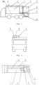
Fig. 1 is a front-view diagram of an embodiment of a mobile inspection apparatus of the present disclosure in a transport state. -
Fig. 2 is a left-view diagram of an embodiment of a mobile inspection apparatus of the present disclosure in a transport state. -
Fig. 3 is a top-view diagram of an embodiment of a mobile inspection apparatus of the present disclosure in a transport state. -
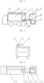
Fig. 4 is a front-view diagram of an embodiment of a mobile inspection apparatus of the present disclosure in a first intermediate state. -
Fig. 5 is a left-view diagram of an embodiment of a mobile inspection apparatus of the present disclosure in a first intermediate state. -
Fig. 6 is a top-view diagram of an embodiment of a mobile inspection apparatus of the present disclosure in a first intermediate state. -
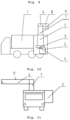
Fig. 7 is a front-view diagram of an embodiment of a mobile inspection apparatus of the present disclosure in a second intermediate state. -
Fig. 8 is a left-view diagram of an embodiment of a mobile inspection apparatus of the present disclosure in a second intermediate state. -
Fig. 9 is a top-view diagram of an embodiment of a mobile inspection apparatus of the present disclosure in a second intermediate state. -
Fig. 10 is a front-view diagram of an embodiment of a mobile inspection apparatus of the present disclosure in a third intermediate state. -
Fig. 11 is a left-view diagram of an embodiment of a mobile inspection apparatus of the present disclosure in a third intermediate state. -
Fig. 12 is a top-view diagram of an embodiment of a mobile inspection apparatus of the present disclosure in a third intermediate state. -
Fig. 13 is a front-view diagram of an embodiment of a mobile inspection apparatus of the present disclosure in an inspection state. -
Fig. 14 is a left-view diagram of an embodiment of a mobile inspection apparatus of the present disclosure in an inspection state. -
Fig. 15 is a top-view diagram of an embodiment of a mobile inspection apparatus of the present disclosure in an inspection state. -
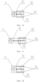
Fig. 16 is a structural diagram illustrating a second support portion retracting relative to a first support portion in an embodiment of a mobile inspection apparatus of the present disclosure. -
Fig. 17 is a structural diagram illustrating a second support portion extending relative to a first support portion in an embodiment of a mobile inspection apparatus of the present disclosure. -
Fig. 18 is a structural diagram illustrating a second support portion retracting relative to a first support portion in another embodiment of a mobile inspection apparatus of the present disclosure. -
Fig. 19 is a structural diagram illustrating a second support portion extending relative to a first support portion in another embodiment of a mobile inspection apparatus of the present disclosure. - 1, first cabin; 2, second cabin; 3, first support member; 4, first drive device; 5, ray source; 6, fourth support portion; 7, third support portion; 8, first detection arm; 9, second detection arm; 10, object under inspection; 11, target point; 12, second support member; 31, first support portion; 32, second support portion; 33, second drive device; 34, guide rail.
- Technical solutions in the embodiments will be described below clearly and completely in conjunction with the accompanying drawings in the embodiments of the present disclosure. Obviously, the described embodiments are only a part of the embodiments of the present disclosure, and not all the embodiments. Based on the embodiments in the present disclosure, all of other embodiments obtained by those of ordinary skill in the art without creative work should fall into the protection scope of the present disclosure.
- In description of the invention in present disclosure, it should be understood that orientation or position relations denoted by the terms "center", "transverse", "longitudinal", "front", "rear", "left", "right", "upper", "lower", "vertical", "horizontal", "top", "bottom", "inner", "outer" and the like are orientation or position relations illustrated based on the drawings, and are merely for the convenience of describing the invention in present disclosure and simplifying description, instead of indicating or implying the denoted devices or elements must have specific orientations or be constructed and operated in specific orientations, and thus the terms cannot be construed as limiting the protection scope of the invention in present disclosure.
- Referring to
Figs. 1 to 15 , in some embodiments of a mobile inspection apparatus provided in the present disclosure, the inspection apparatus includes a movingbody 100, a support assembly, aray source 5, adetector 13, and afirst drive device 4. The movingbody 100 is arranged movably. The support assembly is mounted on the movingbody 100, and the support assembly is configured to retract relative to the movingbody 100 in a transport state of the mobile inspection apparatus and to extend relative to the movingbody 100 in an inspection state of the mobile inspection apparatus. Theray source 5 and thedetector 13 are both mounted on the support assembly. Thefirst drive device 4 is configured to drive the support assembly to rotate relative to the movingbody 100 so as to switch theray source 5 and thedetector 13 between a retracted position and an operating position, such that in the transport state, theray source 5 and thedetector 13 are in the retracted position, and in the inspection state, theray source 5 and thedetector 13 are in the operating position. - In the above embodiment, the support assembly is capable of extending and retracting relative to the moving
body 100. In the inspection state, the support assembly extends to facilitate the rotation of the support assembly relative to the movingbody 100 so as to rotate theray source 5 and thedetector 13 to the operating position. In the transport state, the support assembly retracts to shorten the overall length of the mobile inspection apparatus so as to meet the requirement of traveling on the road, and to be conducive to improving the safety during transport. - The support assembly is configured as a structure capable of extending and retracting relative to the moving
body 100, such that the center of gravity of the movingbody 100 is shifted forward. In this way, a load on a rear axle can be reduced, thereby improving the force-bearing condition of the axle and improving the overall steadiness of the inspection apparatus. - In some embodiments, in the retracted position, the
first drive device 4 is configured to drive theray source 5 and thedetector 13 to move to positions arranged along a moving direction of the movingbody 100. This configuration facilitates retraction of theray source 5 and thedetector 13 into the range of the movingbody 100, to prevent interference or collision with other items during transport. - In the operating position, the
first drive device 4 is configured to drive theray source 5 and thedetector 13 to move to two sides of the movingbody 100, respectively. This configuration facilitates relative deployment of theray source 5 and thedetector 13, and an inspection passage between theray source 5 and thedetector 13 can be formed to facilitate implementation of inspection. Theray source 5 and thedetector 13 being located on two sides of the movingbody 100 respectively can also achieve a counterweight balance of the two sides of the movingbody 100, to avoid tipping over of the movingbody 100. - In some embodiments, the
ray source 5 and thedetector 13 are arranged at such positions that in the retracted position, atarget point 11 of theray source 5 and a mounting plane of thedetector 13 are located on a same side of a first plane. The first plane is parallel to the moving direction of the movingbody 100 and passes through the center of rotation of the support assembly. An advantage of this configuration is that when theray source 5 and thedetector 13 move from the retracted position to the operating position, theray source 5 and thedetector 13 are just at opposite positions, therefore it is convenient to cause thedetector 13 to receive a ray emitted by theray source 5 without special adjustment, which is conducive to saving adjustment time and improving inspection efficiency. - In some embodiments, the support assembly includes a
first support member 3 and asecond support member 12. Theray source 5 is mounted on thefirst support member 3, and thedetector 13 is mounted on thesecond support member 12. Thefirst support member 3 and thesecond support member 12 are both in drive connection with thefirst drive device 4. - By providing the two individual support members, the
ray source 5 and thedetector 13 can be independently supported, respectively, to facilitate performing structural designs thereof, respectively. - In some embodiments, the
first support member 3 and thesecond support member 12 are interconnected into a whole, which facilitates thefirst drive device 4 driving thefirst support member 3 and thesecond support member 12 to rotate together. In this way, the movements of thefirst support member 3 and thesecond support member 12 can be synchronized, thus keeping rotations of theray source 5 and thedetector 13 synchronized. - In some other embodiments, the
first support member 3 and thesecond support member 12 are independent relative to each other, and thefirst support member 3 and thesecond support member 12 are capable of moving relative to each other. This facilitates thefirst drive device 4 respectively driving thefirst support member 3 and thesecond support member 12 to rotate independently relative to each other, thereby adjusting relative positions of theray source 5 and thedetector 13 in real time as needed to meet the inspection requirement. - In an embodiment where the
first drive device 4 respectively drives thefirst support member 3 and thesecond support member 12 to rotate independently relative to each other, thefirst drive device 4 can include a first drive member for driving thefirst support member 3 to rotate and a second drive member for driving thesecond support member 12 to rotate. The structures of the first drive member and the second drive member may be same or different. - The
first drive device 4 can be a rotary drive element such as a revolving platform. - In some embodiments, the
first support member 3 includes a cantilevered portion extending beyond the movingbody 100, and theray source 5 is mounted to the cantilevered portion. The cantilevered portion for supporting theray source 5 is suspended at a rear side of the movingbody 100 and is located outside the movingbody 100. This configuration facilitates formation of an inspection passage between theray source 5 and thedetector 13 when theray source 5 is rotated to the operating position, to avoid the presence of other components between theray source 5 and thedetector 13, which otherwise affects ray transmission and inspection quality. - In some embodiments, the
first support member 3 includes afirst support portion 31 and asecond support portion 32. Thefirst support portion 31 is in drive connection with thefirst drive device 4, and thesecond support portion 32 is movable relative to thefirst support portion 31 to adjust the length of thefirst support member 3. - For example, the
first support portion 31 is fixed relative to the movingbody 100, and thesecond support portion 32 is retractable relative to thefirst support portion 31 so as to adjust the length of thefirst support member 3, thereby adjusting the length of the support assembly and the overall length of the inspection apparatus. - In some embodiments, the support assembly further includes a
second drive device 33. Thesecond drive device 33 is connected to thesecond support portion 32 to drive thesecond support portion 32 to move relative to thefirst support portion 31. Thesecond drive device 33 can be an oil cylinder, an air cylinder, an electric drive pusher, or the like. - A gear-chain, gear-rack or other transmission mechanism can also be provided between the
second drive device 33 and thesecond support portion 32 to achieve transmission of motive power. - In some embodiments, the support assembly further includes a guide member arranged between the
first support portion 31 and thesecond support portion 32. The guide member is configured to guide the movement of thesecond support portion 32. - By providing the guide member, the movement of the
second support portion 32 can be guided so that thesecond support portion 32 moves along a preset route to improve the accuracy and reliability of the movement. - In some embodiments, the guide member includes a
guide rail 34, the width of thefirst support portion 31 is greater or smaller than the width of thesecond support portion 32, thesecond support portion 32 is slidably cooperating with thefirst support portion 31 by means of theguide rail 34. - As shown in
Figs. 16 and 17 , the width of thefirst support portion 31 is smaller than the width of thesecond support portion 32, and thesecond support portion 32 extends/retracts along the guide rail relative to thefirst support portion 31. - As shown in
Figs. 18 and19 , the width of thefirst support portion 31 is greater than the width of thesecond support portion 32, and thesecond support portion 32 extends/retracts along the guide rail relative to thefirst support portion 31. - The guide rail may be a structure of two sets of rails cooperating with each other, or a structure of a rail and a slider cooperating with the slider, which will not be detailed here.
- In other embodiments, the
first support portion 31 and thesecond support portion 32 may also cooperate with each other in a rolling manner. For example, a rolling bearing is provided between thefirst support portion 31 and thesecond support portion 32. - In some embodiments, the mobile inspection apparatus further includes a
first cabin 1. Thefirst cabin 1 is mounted on the movingbody 100. Thesecond support member 12 includes athird support portion 7 and afourth support portion 6. Thefirst drive device 4 is arranged in thefirst cabin 1. Thethird support portion 7 is in drive connection with thefirst drive device 4. In the transport state, thefourth support portion 6 is supported on the top of thefirst cabin 1. - By providing the
first cabin 1, components mounted on the movingbody 100 and located inside thefirst cabin 1 can be protected. Moreover, the top of thefirst cabin 1 can also support thefourth support portion 6 in the transport state. - For example, the
second support member 12 includes athird support portion 7 arranged vertically and afourth support portion 6 arranged horizontally, and thefourth support portion 6 is connected to thethird support portion 7. Thethird support portion 7 is a vertically extensible structure. In the inspection state, thethird support portion 7 is vertically lengthened, and in the transport state, thethird support portion 7 is vertically shortened so that thefourth support portion 6 can be supported on the top of thefirst cabin 1. - The
second support member 12 can further include afirst detection arm 8 and asecond detection arm 9. Thefirst detection arm 8 is arranged horizontally and mounted to a side of thefourth support portion 6. Thesecond detection arm 9 is rotatably connected to thefirst detection arm 8. In the transport state, thesecond detection arm 9 is folded relative to thefirst detection arm 8, and thesecond detection arm 9 is rotated to a position parallel to thefirst detection arm 8, and thesecond detection arm 9 is located below thefirst detection arm 8. In the inspection state, thesecond detection arm 9 is unfolded relative to thefirst detection arm 8, and thesecond detection arm 9 is rotated to a position perpendicular to thefirst detection arm 8, such that a foldable portal frame is formed by thefirst detection arm 8, thesecond detection arm 9, thethird support portion 7 and thefourth support portion 6 together, and an inspection passage is formed by the vertically arrangedthird support portion 7 and thesecond detection arm 9. -
Detectors 13 are provided on both thefirst detection arm 8 and thesecond detection arm 9 to receive a ray emitted by theray source 5. - In other embodiments, the
second support member 12 may also be other feasible structure. - In some embodiments, the mobile inspection apparatus further includes a
second cabin 2. Thesecond cabin 2 is mounted on thefirst support member 3, and theray source 5 is arranged in thesecond cabin 2. Thesecond cabin 2 is provided with a through hole aligned with an outgoing port of theray source 5 to facilitate ray emission. - By providing the
second cabin 2, theray source 5 can be effectively protected. Furthermore, thesecond cabin 2 together with thefirst cabin 1 forms an entire cabin of the inspection apparatus. - In some embodiments, a portion of the
ray source 5 is arranged inside thesecond cabin 2, and another portion thereof is arranged outside thesecond cabin 2. For example, theray source 5 is arranged at the bottom of thesecond cabin 2, and a lower part of theray source 5 is exposed from the bottom of thesecond cabin 2. In this way, theray source 5 can be protected, and ray emission of theray source 5 is not affected. - In some embodiments, the
first cabin 1 and thesecond cabin 2 are in contact with each other in the transport state to avoid a gap between thefirst cabin 1 and thesecond cabin 2, which otherwise affects aesthetics. - The
first cabin 1 and thesecond cabin 2 being in contact with each other may mean that a rear side of thefirst cabin 1 and a front side of thesecond cabin 2 are entirely in contact with each other, or only left and right side plates of thefirst cabin 1 and left and right side plates of thesecond cabin 2 are in partial contact with each other. - In some embodiments, there is a preset gap between the
first cabin 1 and thesecond cabin 2 in the transport state. The gap can be convenient for rotation of thesecond cabin 2 and is relatively easy to implement in manufacturing. - In some embodiments, there is a preset distance between a side of the
first cabin 1 close to thesecond cabin 2 and a side of the movingbody 100 close to thesecond cabin 2. That is, thefirst cabin 1 is not arranged at an edge of the movingbody 100. This preset distance allows a projection 14 to be formed at an end of the movingbody 100 close to thesecond cabin 2. A lower part of a side of thesecond cabin 2 close to thefirst cabin 1 is provided with a recess 15. In this way, in the transport state, the projection 14 is embedded into the recess 15, and the recess 15 is just lapped on a rear side of the movingbody 100, so that the movingbody 100 can partially support thesecond cabin 2. - In some embodiments, the moving
body 100 includes a vehicle chassis. The bottom of the vehicle chassis is equipped with a plurality of wheels, which can travel relative to the ground. The wheels are arranged at the bottom of the movingbody 100. The bottom of thesecond cabin 2 is not equipped with wheels, and the bottom of thesecond cabin 2 is suspended in the air after the support assembly is extended. - A working process of an embodiment of the mobile inspection apparatus of the present disclosure is described below in conjunction with
Figs. 1 to 15 : - In the following, description will be made using the moving direction of the moving
body 100 as a reference direction. The moving direction serves as forward direction and the inverse direction of the moving direction serves as backward direction. - First, as shown in
Figs. 1 to 3 , in the transport state, the support assembly is rotated to a direction parallel to the moving direction of the movingbody 100, such that thefirst support member 3 is in the rear and thesecond support member 12 is in the front. Thesecond support portion 32 of thefirst support member 3 is retracted with respect to the first support portion 31 (see, for example, referring toFigs. 16 and 18 ), and the front side of thesecond cabin 2 is in close contact with the rear side of thefirst cabin 1. Thesecond detection arm 9 of thesecond support member 12 is rotatably arranged below thefirst detection arm 8, thethird support portion 7 is vertically lowered, and thefourth support portion 6, thefirst detection arm 8 and thesecond detection arm 9 are supported on the top of thefirst cabin 1. - Subsequently, as shown in
Figs. 4-6 , thesecond drive device 33 drives thesecond support portion 32 to extend rearward relative to thefirst support portion 31, such that thesecond cabin 2 leaves thefirst cabin 1, and the inspection apparatus enters a first intermediate state, at which time thesecond support member 12 remains motionless (see, for example, referring toFigs. 17 and19 ). - Then, as shown in
Figs. 7-9 , thethird support portion 7 of thesecond support member 12 is vertically raised, such that thefourth support portion 6, thefirst detection arm 8 and thesecond detection arm 9 all leave the top of thefirst cabin 1, and the inspection apparatus enters a second intermediate state. - Then, as shown in
Figs. 10-12 , thefirst drive device 4 drives the support assembly to rotate relative to the movingbody 100, and the support assembly rotates to a direction perpendicular to the moving direction of the movingbody 100, such that theray source 5 and thedetector 13 are located on two sides of the movingbody 100, respectively, and the inspection apparatus enters a third intermediate state. - Finally, as shown in
Figs. 13-15 , thesecond detection arm 9 is unfolded relative to thefirst detection arm 8, and thesecond detection arm 9 rotates to a vertical direction, such that an inspection passage is formed between thethird support portion 7 and thesecond detection arm 9. A ray emitted by theray source 5 is irradiated on an object underinspection 10, and the ray projected or reflected by the object underinspection 10 is received by thedetector 13 to implement scanning inspection of the object underinspection 10. By analyzing a signal received by thedetector 13, it can be determined whether the object underinspection 10 contains a prohibited substance. - In some embodiments, after the
first drive device 4 drives the support assembly to rotate relative to the movingbody 100, and the support assembly rotates to the direction perpendicular to the moving direction of the movingbody 100, such that theray source 5 and thedetector 13 are located on two sides of the movingbody 100, respectively, thethird support portion 7 of thesecond support member 12 can be raised vertically, such that thefourth support portion 6, thefirst detector 13arm 8 and thesecond detector 13arm 9 all leave the top of thefirst cabin 1. - In some other embodiments, while the
second drive device 33 drives thesecond support portion 32 to extend rearward relative to thefirst support portion 31, thefirst drive device 4 can drive the support assembly to rotate relative to the movingbody 100. The extension and the rotation occur and end at the same time. Likewise, retraction and rotation also occur and end at the same time. - The present disclosure also provides a mobile inspection method, the method including:
- providing a movable moving
body 100 and a support assembly mounted on the movingbody 100; - extending the support assembly relative to the moving
body 100; - after extending, driving the support assembly to rotate relative to the moving
body 100 by afirst drive device 4 so that aray source 5 and adetector 13 rotate from a retracted position to an operating position; - starting the
ray source 5 and thedetector 13 to perform scanning inspection on an object to be inspected; - after completion of the inspection, driving the support assembly to rotate relative to the moving
body 100 by thefirst drive device 4 so that theray source 5 and thedetector 13 return from the operating position to the retracted position; and - then, retracting the support assembly relative to the moving
body 100. - The positive technical effects of the mobile inspection apparatus in the embodiments described above are also applicable to the mobile inspection method, and are not repeated here.
- Finally, it should be noted that the above embodiments are only used for describing rather than limiting the technical solutions of the present disclosure. Although the present disclosure is described in detail with reference to the preferred embodiments, those of ordinary skill in the art should understand that they still can make modifications to the specific implementations in the present disclosure or make equivalent substitutions to part of technical features thereof without departing from the principle of the present disclosure. Such modifications and equivalent substitutions should be encompassed within the technical solutions sought for protection in the present disclosure.
Claims (15)
- A mobile inspection apparatus, characterized by comprising:a moving body (100) arranged movably;a support assembly, mounted on the moving body (100), and configured to retract relative to the moving body (100) in a transport state of the mobile inspection apparatus and to extend relative to the moving body (100) in an inspection state of the mobile inspection apparatus;a ray source (5) and a detector (13) mounted on the support assembly; anda first drive device (4) configured to drive the support assembly to rotate relative to the moving body (100) so as to switch the ray source (5) and the detector (13) between a retracted position and an operating position, such that in the transport state, the ray source (5) and the detector (13) are located in the retracted position, and in the inspection state, the ray source (5) and the detector (13) are located in the operating position.
- The mobile inspection apparatus according to claim 1, wherein the first drive device (4) is configured to drive the ray source (5) and the detector (13) to move to positions arranged along a moving direction of the moving body (100) in the retracted position; and drive the ray source (5) and the detector (13) to respectively move to two sides of the moving body (100) in the operating position.
- The mobile inspection apparatus according to claim 1 or 2, wherein the ray source (5) and the detector (13) are arranged at such positions that in the retracted position, a target point (11) of the ray source (5) and a mounting plane of the detector (13) are located on a same side of a first plane, and the first plane is parallel to the moving direction of the moving body (100) and passes through the center of rotation of the support assembly.
- The mobile inspection apparatus according to any one of claims 1 to 3, wherein the support assembly comprises a first support member (3) and a second support member (12), the ray source (5) is mounted on the first support member (3), the detector (13) is mounted on the second support member (12), and the first support member (3) and the second support member (12) are both in drive connection with the first drive device (4).
- The mobile inspection apparatus according to claim 4, wherein the first drive device (4) is configured to drive the first support member (3) and the second support member (12) to rotate simultaneously or to respectively drive the first support member (3) and the second support member (12) to rotate independently relative to each other.
- The mobile inspection apparatus according to claim 4 or 5, wherein the first support member (3) comprises a cantilevered portion extending beyond the moving body (100), and the ray source (5) is mounted on the cantilevered portion.
- The mobile inspection apparatus according to any one of claims 4 to 6, wherein the first support member (3) comprises a first support portion (31) and a second support portion (32), the first support portion (31) is in drive connection with the first drive device (4), and the second support portion (32) is movable relative to the first support portion (31) to adjust the length of the first support member (3).
- The mobile inspection apparatus according to claim 7, wherein the support assembly further comprises a second drive device (33), and the second drive device (33) is connected to the second support portion (32) to drive the second support portion (32) to move relative to the first support portion (31).
- The mobile inspection apparatus according to claim 7 or 8, wherein the support assembly further comprises a guide member arranged between the first support portion (31) and the second support portion (32), and the guide member is configured to guide the movement of the second support portion (32).
- The mobile inspection apparatus according to claim 9, wherein the guide member comprises a guide rail (34), a width of the first support portion (31) is greater or smaller than a width of the second support portion (32), and the second support portion (32) is slidably cooperating with the first support portion (31) by means of the guide rail (34).
- The mobile inspection apparatus according to any one of claims 4 to 10, further comprising a first cabin (1), wherein the first cabin (1) is mounted on the moving body (100), the second support member (12) comprises a third support portion (7) and a fourth support portion (6), the first drive device (4) is arranged in the first cabin (1), the third support portion (7) is in drive connection with the first drive device (4), and the fourth support portion (6) is supported on a top of the first cabin (1) in the transport state.
- The mobile inspection apparatus according to claim 11, further comprising a second cabin (2), wherein the second cabin (2) is mounted on the first support member (3), the ray source (5) is arranged in the second cabin (2), and in the transport state, the first cabin (1) and the second cabin (2) are in contact with each other or there is a preset gap between the first cabin (1) and the second cabin (2).
- The mobile inspection apparatus according to claim 12, wherein there is a preset distance between a side of the first cabin (1) close to the second cabin (2) and a side of the moving body (100) close to the second cabin (2) to form a projection (14) at an end of the moving body (100) close to the second cabin (2), and a lower part of a side of the second cabin (2) close to the first cabin (1) is provided with a recess (15), and the projection (14) is embedded into the recess (15) in the transport state.
- The mobile inspection apparatus according to any one of claim 1 to 13, wherein the moving body (100) comprises a vehicle chassis.
- A mobile inspection method based on the mobile inspection apparatus of any one of claims 1 to 14, characterized by comprising:providing a movable moving body (100) and a support assembly mounted on the moving body (100);extending the support assembly relative to the moving body (100);after extending, driving the support assembly to rotate relative to the moving body (100) by a first drive device (4) so that a ray source (5) and a detector (13) rotate from a retracted position to an operating position;starting the ray source (5) and the detector (13) to perform scanning inspection on an object to be inspected;after completion of the inspection, driving the support assembly to rotate relative to the moving body (100) by the first drive device (4) so that the ray source (5) and the detector (13) return from the operating position to the retracted position; and thenretracting the support assembly relative to the moving body (100) .
Applications Claiming Priority (1)
| Application Number | Priority Date | Filing Date | Title |
|---|---|---|---|
| CN202111661878.6A CN114167509B (en) | 2021-12-30 | 2021-12-30 | Mobile inspection equipment and mobile inspection method |
Publications (1)
| Publication Number | Publication Date |
|---|---|
| EP4206750A1 true EP4206750A1 (en) | 2023-07-05 |
Family
ID=80489058
Family Applications (1)
| Application Number | Title | Priority Date | Filing Date |
|---|---|---|---|
| EP22217029.2A Pending EP4206750A1 (en) | 2021-12-30 | 2022-12-28 | Mobile inspection apparatus and mobile inspection method |
Country Status (3)
| Country | Link |
|---|---|
| EP (1) | EP4206750A1 (en) |
| CN (1) | CN114167509B (en) |
| WO (1) | WO2023125122A1 (en) |
Families Citing this family (1)
| Publication number | Priority date | Publication date | Assignee | Title |
|---|---|---|---|---|
| CN114167509B (en) * | 2021-12-30 | 2025-07-15 | 同方威视科技(北京)有限公司 | Mobile inspection equipment and mobile inspection method |
Citations (6)
| Publication number | Priority date | Publication date | Assignee | Title |
|---|---|---|---|---|
| WO2009088706A2 (en) * | 2007-12-19 | 2009-07-16 | Rapiscan Security Products, Inc. | Rotatable boom cargo scanning system |
| US20110038453A1 (en) * | 2002-07-23 | 2011-02-17 | Edward James Morton | Compact Mobile Cargo Scanning System |
| CN107064186A (en) * | 2017-04-17 | 2017-08-18 | 北京体通探测技术有限公司 | A kind of workbench of vehicular rays safety detection apparatus and the vehicular rays safety detection apparatus with the platform |
| EP3561550A1 (en) * | 2016-12-26 | 2019-10-30 | Nuctech Company Limited | Mobile bomb disposal transmission imaging apparatus |
| EP3715838A1 (en) * | 2017-11-21 | 2020-09-30 | Nuctech Company Limited | Vehicle-mounted radiation inspection system |
| CN112946770A (en) * | 2021-05-17 | 2021-06-11 | 同方威视技术股份有限公司 | Scanning inspection apparatus and scanning inspection system |
Family Cites Families (11)
| Publication number | Priority date | Publication date | Assignee | Title |
|---|---|---|---|---|
| CN1181336C (en) * | 2002-10-16 | 2004-12-22 | 清华大学 | A vehicle-mounted mobile container inspection system |
| US6937692B2 (en) * | 2003-06-06 | 2005-08-30 | Varian Medical Systems Technologies, Inc. | Vehicle mounted inspection systems and methods |
| CN102147485B (en) * | 2006-10-13 | 2012-08-29 | 同方威视技术股份有限公司 | Mobile vehicle detecting system |
| EP2433152B1 (en) * | 2009-05-22 | 2021-07-07 | Rapiscan Systems, Inc. | Compact mobile cargo scanning system |
| CN104244561A (en) * | 2013-06-21 | 2014-12-24 | 同方威视技术股份有限公司 | Standing wave electron linear accelerator and container/vehicle inspection system |
| CN105445294B (en) * | 2014-09-02 | 2019-02-22 | 清华大学 | Vehicle-mounted inspection system |
| CN107861165A (en) * | 2017-10-17 | 2018-03-30 | 青岛新前湾集装箱码头有限责任公司 | Portable commodity inspection system |
| CN108398726A (en) * | 2018-05-09 | 2018-08-14 | 清华大学 | Radiation checking system and port facilities |
| CN112730473B (en) * | 2021-03-30 | 2021-07-27 | 同方威视技术股份有限公司 | Radiographic inspection equipment, and vehicle security inspection system |
| CN216561041U (en) * | 2021-12-30 | 2022-05-17 | 同方威视科技(北京)有限公司 | Mobile inspection apparatus |
| CN114167509B (en) * | 2021-12-30 | 2025-07-15 | 同方威视科技(北京)有限公司 | Mobile inspection equipment and mobile inspection method |
-
2021
- 2021-12-30 CN CN202111661878.6A patent/CN114167509B/en active Active
-
2022
- 2022-12-20 WO PCT/CN2022/140198 patent/WO2023125122A1/en not_active Ceased
- 2022-12-28 EP EP22217029.2A patent/EP4206750A1/en active Pending
Patent Citations (6)
| Publication number | Priority date | Publication date | Assignee | Title |
|---|---|---|---|---|
| US20110038453A1 (en) * | 2002-07-23 | 2011-02-17 | Edward James Morton | Compact Mobile Cargo Scanning System |
| WO2009088706A2 (en) * | 2007-12-19 | 2009-07-16 | Rapiscan Security Products, Inc. | Rotatable boom cargo scanning system |
| EP3561550A1 (en) * | 2016-12-26 | 2019-10-30 | Nuctech Company Limited | Mobile bomb disposal transmission imaging apparatus |
| CN107064186A (en) * | 2017-04-17 | 2017-08-18 | 北京体通探测技术有限公司 | A kind of workbench of vehicular rays safety detection apparatus and the vehicular rays safety detection apparatus with the platform |
| EP3715838A1 (en) * | 2017-11-21 | 2020-09-30 | Nuctech Company Limited | Vehicle-mounted radiation inspection system |
| CN112946770A (en) * | 2021-05-17 | 2021-06-11 | 同方威视技术股份有限公司 | Scanning inspection apparatus and scanning inspection system |
Also Published As
| Publication number | Publication date |
|---|---|
| CN114167509A (en) | 2022-03-11 |
| WO2023125122A1 (en) | 2023-07-06 |
| CN114167509B (en) | 2025-07-15 |
Similar Documents
| Publication | Publication Date | Title |
|---|---|---|
| US20240411045A1 (en) | Mobile radiation inspection apparatus and mobile radiation inspection system | |
| CN101162206B (en) | Mobile Vehicle Inspection System | |
| CN104459811B (en) | Vehicle-mounted removable container or vehicle inspection system | |
| CN116297559B (en) | Security inspection system | |
| CN112946770B (en) | Scanning and checking equipment and scanning and checking systems | |
| BR102019014290A2 (en) | radiation inspection system | |
| PL246521B1 (en) | Security Check Device and Method of Moving It | |
| US20220099858A1 (en) | Security inspection device | |
| CN109633767B (en) | Inspection device and transition method based on inspection device | |
| CN115616672A (en) | Radar Detection Vehicle for Tunnel Geological Data Acquisition | |
| CN109490977A (en) | Check equipment | |
| CN217060528U (en) | Mobile radiation inspection equipment and mobile radiation inspection systems | |
| CN216561041U (en) | Mobile inspection apparatus | |
| CN114167509B (en) | Mobile inspection equipment and mobile inspection method | |
| CN101936925A (en) | Vehicle-mounted container detection system of semi-trailer | |
| CN117871555A (en) | Mobile inspection device and mobile inspection system | |
| CN102147485B (en) | Mobile vehicle detecting system | |
| CN219084794U (en) | Security check system | |
| CN206339666U (en) | Portable explosive transmission imaging device | |
| CN201440131U (en) | Semi-trailer vehicle-mounted radiation detection system | |
| CN102147487B (en) | Mobile vehicle inspection system | |
| CN115144919B (en) | Radiographic inspection equipment and vehicle-mounted security inspection system | |
| CN200989886Y (en) | Moving vehicle inspection system | |
| CN115144921B (en) | Radiographic inspection equipment and vehicle-mounted security inspection systems | |
| CN215322545U (en) | Intelligent inspection device for railway communication machine room |
Legal Events
| Date | Code | Title | Description |
|---|---|---|---|
| PUAI | Public reference made under article 153(3) epc to a published international application that has entered the european phase |
Free format text: ORIGINAL CODE: 0009012 |
|
| STAA | Information on the status of an ep patent application or granted ep patent |
Free format text: STATUS: REQUEST FOR EXAMINATION WAS MADE |
|
| 17P | Request for examination filed |
Effective date: 20221228 |
|
| AK | Designated contracting states |
Kind code of ref document: A1 Designated state(s): AL AT BE BG CH CY CZ DE DK EE ES FI FR GB GR HR HU IE IS IT LI LT LU LV MC ME MK MT NL NO PL PT RO RS SE SI SK SM TR |
|
| STAA | Information on the status of an ep patent application or granted ep patent |
Free format text: STATUS: EXAMINATION IS IN PROGRESS |
|
| 17Q | First examination report despatched |
Effective date: 20250522 |