EP4206746A1 - Heat dissipation structure and inspection apparatus - Google Patents
Heat dissipation structure and inspection apparatus Download PDFInfo
- Publication number
- EP4206746A1 EP4206746A1 EP22217362.7A EP22217362A EP4206746A1 EP 4206746 A1 EP4206746 A1 EP 4206746A1 EP 22217362 A EP22217362 A EP 22217362A EP 4206746 A1 EP4206746 A1 EP 4206746A1
- Authority
- EP
- European Patent Office
- Prior art keywords
- plate
- heat
- radiator
- supporting frame
- dissipation structure
- Prior art date
- Legal status (The legal status is an assumption and is not a legal conclusion. Google has not performed a legal analysis and makes no representation as to the accuracy of the status listed.)
- Granted
Links
Images


Classifications
-
- G—PHYSICS
- G01—MEASURING; TESTING
- G01V—GEOPHYSICS; GRAVITATIONAL MEASUREMENTS; DETECTING MASSES OR OBJECTS; TAGS
- G01V5/00—Prospecting or detecting by the use of ionising radiation, e.g. of natural or induced radioactivity
- G01V5/20—Detecting prohibited goods, e.g. weapons, explosives, hazardous substances, contraband or smuggled objects
- G01V5/22—Active interrogation, i.e. by irradiating objects or goods using external radiation sources, e.g. using gamma rays or cosmic rays
- G01V5/226—Active interrogation, i.e. by irradiating objects or goods using external radiation sources, e.g. using gamma rays or cosmic rays using tomography
-
- A—HUMAN NECESSITIES
- A61—MEDICAL OR VETERINARY SCIENCE; HYGIENE
- A61B—DIAGNOSIS; SURGERY; IDENTIFICATION
- A61B6/00—Apparatus or devices for radiation diagnosis; Apparatus or devices for radiation diagnosis combined with radiation therapy equipment
- A61B6/44—Constructional features of apparatus for radiation diagnosis
- A61B6/4488—Means for cooling
-
- A—HUMAN NECESSITIES
- A61—MEDICAL OR VETERINARY SCIENCE; HYGIENE
- A61B—DIAGNOSIS; SURGERY; IDENTIFICATION
- A61B6/00—Apparatus or devices for radiation diagnosis; Apparatus or devices for radiation diagnosis combined with radiation therapy equipment
- A61B6/02—Arrangements for diagnosis sequentially in different planes; Stereoscopic radiation diagnosis
- A61B6/03—Computed tomography [CT]
- A61B6/032—Transmission computed tomography [CT]
- A61B6/035—Mechanical aspects of CT
-
- F—MECHANICAL ENGINEERING; LIGHTING; HEATING; WEAPONS; BLASTING
- F28—HEAT EXCHANGE IN GENERAL
- F28D—HEAT-EXCHANGE APPARATUS, NOT PROVIDED FOR IN ANOTHER SUBCLASS, IN WHICH THE HEAT-EXCHANGE MEDIA DO NOT COME INTO DIRECT CONTACT
- F28D1/00—Heat-exchange apparatus having stationary conduit assemblies for one heat-exchange medium only, the media being in contact with different sides of the conduit wall, in which the other heat-exchange medium is a large body of fluid, e.g. domestic or motor car radiators
- F28D1/02—Heat-exchange apparatus having stationary conduit assemblies for one heat-exchange medium only, the media being in contact with different sides of the conduit wall, in which the other heat-exchange medium is a large body of fluid, e.g. domestic or motor car radiators with heat-exchange conduits immersed in the body of fluid
- F28D1/03—Heat-exchange apparatus having stationary conduit assemblies for one heat-exchange medium only, the media being in contact with different sides of the conduit wall, in which the other heat-exchange medium is a large body of fluid, e.g. domestic or motor car radiators with heat-exchange conduits immersed in the body of fluid with plate-like or laminated conduits
-
- F—MECHANICAL ENGINEERING; LIGHTING; HEATING; WEAPONS; BLASTING
- F28—HEAT EXCHANGE IN GENERAL
- F28D—HEAT-EXCHANGE APPARATUS, NOT PROVIDED FOR IN ANOTHER SUBCLASS, IN WHICH THE HEAT-EXCHANGE MEDIA DO NOT COME INTO DIRECT CONTACT
- F28D1/00—Heat-exchange apparatus having stationary conduit assemblies for one heat-exchange medium only, the media being in contact with different sides of the conduit wall, in which the other heat-exchange medium is a large body of fluid, e.g. domestic or motor car radiators
- F28D1/02—Heat-exchange apparatus having stationary conduit assemblies for one heat-exchange medium only, the media being in contact with different sides of the conduit wall, in which the other heat-exchange medium is a large body of fluid, e.g. domestic or motor car radiators with heat-exchange conduits immersed in the body of fluid
- F28D1/04—Heat-exchange apparatus having stationary conduit assemblies for one heat-exchange medium only, the media being in contact with different sides of the conduit wall, in which the other heat-exchange medium is a large body of fluid, e.g. domestic or motor car radiators with heat-exchange conduits immersed in the body of fluid with tubular conduits
- F28D1/053—Heat-exchange apparatus having stationary conduit assemblies for one heat-exchange medium only, the media being in contact with different sides of the conduit wall, in which the other heat-exchange medium is a large body of fluid, e.g. domestic or motor car radiators with heat-exchange conduits immersed in the body of fluid with tubular conduits the conduits being straight
-
- G—PHYSICS
- G01—MEASURING; TESTING
- G01N—INVESTIGATING OR ANALYSING MATERIALS BY DETERMINING THEIR CHEMICAL OR PHYSICAL PROPERTIES
- G01N23/00—Investigating or analysing materials by the use of wave or particle radiation, e.g. X-rays or neutrons, not covered by groups G01N3/00 – G01N17/00, G01N21/00 or G01N22/00
- G01N23/02—Investigating or analysing materials by the use of wave or particle radiation, e.g. X-rays or neutrons, not covered by groups G01N3/00 – G01N17/00, G01N21/00 or G01N22/00 by transmitting the radiation through the material
- G01N23/04—Investigating or analysing materials by the use of wave or particle radiation, e.g. X-rays or neutrons, not covered by groups G01N3/00 – G01N17/00, G01N21/00 or G01N22/00 by transmitting the radiation through the material and forming images of the material
- G01N23/046—Investigating or analysing materials by the use of wave or particle radiation, e.g. X-rays or neutrons, not covered by groups G01N3/00 – G01N17/00, G01N21/00 or G01N22/00 by transmitting the radiation through the material and forming images of the material using tomography, e.g. computed tomography [CT]
-
- G—PHYSICS
- G01—MEASURING; TESTING
- G01T—MEASUREMENT OF NUCLEAR OR X-RADIATION
- G01T1/00—Measuring X-radiation, gamma radiation, corpuscular radiation, or cosmic radiation
- G01T1/29—Measurement performed on radiation beams, e.g. position or section of the beam; Measurement of spatial distribution of radiation
- G01T1/2914—Measurement of spatial distribution of radiation
- G01T1/2985—In depth localisation, e.g. using positron emitters; Tomographic imaging (longitudinal and transverse section imaging; apparatus for radiation diagnosis sequentially in different planes, steroscopic radiation diagnosis)
-
- H—ELECTRICITY
- H05—ELECTRIC TECHNIQUES NOT OTHERWISE PROVIDED FOR
- H05G—X-RAY TECHNIQUE
- H05G1/00—X-ray apparatus involving X-ray tubes; Circuits therefor
- H05G1/02—Constructional details
- H05G1/025—Means for cooling the X-ray tube or the generator
-
- F—MECHANICAL ENGINEERING; LIGHTING; HEATING; WEAPONS; BLASTING
- F28—HEAT EXCHANGE IN GENERAL
- F28D—HEAT-EXCHANGE APPARATUS, NOT PROVIDED FOR IN ANOTHER SUBCLASS, IN WHICH THE HEAT-EXCHANGE MEDIA DO NOT COME INTO DIRECT CONTACT
- F28D21/00—Heat-exchange apparatus not covered by any of the groups F28D1/00 - F28D20/00
- F28D2021/0019—Other heat exchangers for particular applications; Heat exchange systems not otherwise provided for
- F28D2021/0028—Other heat exchangers for particular applications; Heat exchange systems not otherwise provided for for cooling heat generating elements, e.g. for cooling electronic components or electric devices
- F28D2021/0029—Heat sinks
Definitions
- the present disclosure relates to a field of security inspection, and in particular to a heat dissipation structure and an inspection apparatus.
- the CT inspection apparatus is widely used in a variety of inspections, and has currently been used for security inspection of baggage articles.
- an X-ray generator and a detection device are installed on a circular frame for rotary motion.
- a space limited by a central hole of the circular frame constitutes an inspection channel. Due to a large amount of heat generated when using a ray source, it is necessary to cool the ray source.
- the existing inspection apparatus is generally equipped with a fan to cool a radiator of the inspection apparatus, which makes the inspection apparatus complex in structure and frequent in failures. The fan may cause safety risks during use.
- a heat dissipation structure including: a supporting frame configured to rotate around a central axis of the supporting frame; a heat source arranged on the supporting frame and configured to rotate with the supporting frame; and a radiator configured to receive from the heat source a fluid heated by the heat source and input the cooled fluid to the heat source; wherein the radiator is arranged on a periphery of the supporting frame relative to the central axis, and when the supporting frame rotates around the central axis of the supporting frame, the radiator is configured to allow air to enter into the radiator via an air inlet opening of the radiator and to be expelled from the radiator via an air outlet opening of the radiator.
- the radiator includes a first plate and a second plate, the first plate and the second plate are opposite each other to allow the air to pass between the first plate and the second plate so as to remove heat from the first plate and the second plate, and the first plate is farther away from the central axis than the second plate.
- the radiator includes a heat pipe arranged in the first plate and the second plate, and the fluid flows through the heat pipe.
- the radiator includes a plurality of heat sinks, and the plurality of heat sinks are connected between the first plate and the second plate and spaced apart from each other, so that two adjacent heat sinks between the first plate and the second plate define a channel allowing the air to flow.
- the plurality of heat sinks are arranged between the first plate and the second plate in parallel.
- the plurality of heat sinks are arranged to extend between the first plate and the second plate, and each of the plurality of heat sinks is at an angle with respect to a tangent direction of a circumferential trajectory of the plurality of heat sinks when the plurality of heat sinks rotate around the central axis.
- each of the plurality of heat sinks is arranged to extend meanderingly from the air inlet opening to the air outlet opening between the first plate and the second plate.
- each of the plurality of heat sinks is arranged to extend meanderingly in a radial direction relative to the central axis between the first plate and the second plate.
- the radiator further includes at least one connecting plate fixedly connected between the first plate and the second plate.
- the at least one connecting plate, the first plate and the second plate form a box structure, the box structure defining the air inlet opening, the air outlet opening and a gas path between the air inlet opening and the air outlet opening.
- an area of the first plate is not equal to an area of the second plate.
- the heat dissipation structure further includes a pump configured to pump the fluid out of the heat source and pump the fluid into the radiator, so that the fluid circulates between the heat source and the radiator.
- the heat dissipation structure further includes a container configured to be in fluid connection with the heat source, and the container is capable of storing the fluid pumped out of the heat source.
- the fluid is water or oil.
- an inspection apparatus including the heat dissipation structure described above, wherein the heat source is a ray source arranged on the supporting frame to emit rays; wherein the supporting frame is configured to define an inspection channel passing an axis of the supporting frame.
- the ray source is carried by the supporting frame to rotate around the inspection channel, and when the ray source rotates, the ray source is configured to emit rays toward an inspected object to acquire a three-dimensional image of the inspected object.
- first”, “second”, and the like are used to distinguish different components, rather than sequencing or indicating primary or secondary.
- Terms “upper”, “lower”, and the like indicating orientations in the specification do not indicate an absolute orientation, but indicate a relative position between components.
- the embodiments of the present disclosure provide a heat dissipation structure including a supporting frame 50, and the supporting frame is used to rotate around a central axis O of the supporting frame.
- the supporting frame 50 shown in FIG. 1 is generally cylindrical in shape, defining a circular channel penetrating the supporting frame 50.
- the supporting frame 50 may carry a measuring tool or a processing tool, as well as devices such as a radiator 30, a motor and the like.
- the supporting frame 50 is rotatable for operation of the tool carried thereon.
- the supporting frame 50 is a ring.
- the supporting frame 50 may be a frame having another shape.
- the heat dissipation structure includes a heat source 40 arranged on the supporting frame 50 and rotating with the supporting frame 50.
- the heat source 40 may be the measuring tool or the processing tool.
- the heat source 40 may be a ray source.
- the ray source may emit a ray which may generate a large amount of heat during operation, and thus a heat dissipation is required.
- the heat source 40 may be a heat source 40 of another type, which is mounted on a part of the supporting frame 50.
- the heat dissipation structure includes a radiator 30 configured to receive a fluid heated by the heat source 40 from the heat source 40 and input the cooled fluid to the heat source 40.
- a radiator 30 for the fluid is advantageous, which allows the fluid to circulate between the heat source and the radiator 30 so as to transfer the heat generated by the heat source to the radiator 30.
- the radiator 30 may be separated from the heat source 40, so that an arrangement of the apparatus is more flexible.
- the circulation of the fluid may be realized through a heat pipe, which is included inside the heat source 40 and the radiator 30, and the fluid flows in the heat pipe.
- the circulation may be achieved by a pump 31 driving the fluid to flow inside the heat pipe inside the heat source and the radiator 30.
- the heat pipe may be a metal pipe, a ceramic pipe or a pipe formed by other heat conductive materials.
- the pump 31 is arranged to allow the fluid in the heat pipe to pass through the pump 31, and the pump 31 drives the fluid to flow.
- the pump 31 is configured to pump the fluid out of the heat source 40 and pump the fluid into the radiator 30 so that the fluid circulates between the heat source 40 and the radiator 30.
- the heat dissipation structure further includes a container configured to be in fluid connection with the heat source 40 and capable of storing the fluid pumped from the heat source 40. The fluid in the container flows into the radiator for cooling under an action of the pump.
- the fluid heated by the heat source first flows into a container such as a water tank 32 and then flows into the radiator 30, the fluid flows back to the heat source after cooling.
- the pump 31 may be fixed on the water tank 32, so that a structure is more compact.
- the water tank 32 may make the fluid flow more uniformly in the heat pipe, and an impact brought by the pump may be buffered.
- the pump 31 may be located in another location or may be arranged separately from the water tank 32.
- the container may be a glass container or the like.
- the fluid used for heat dissipation is water, aqueous solution, oil or other liquids.
- the radiator 30 is arranged on a periphery of the supporting frame 50 relative to the central axis O, and the radiator 30 allows air to enter into the radiator 30 via an air inlet opening 30-1 of the radiator 30 and allows the air to be expelled from the radiator 30 via an air outlet opening 30-O of the radiator 30 when the supporting frame 50 rotates around the central axis O of the supporting frame 50.
- FIG. 3 shows a schematic diagram of the radiator 30 moving in a circle with the supporting frame 50. As shown in FIG. 3 , it is advantageous for the radiator 30 to be arranged on the periphery of the supporting frame 50 relative to the central axis O.
- the radiator 30 when the supporting frame 50 rotates, the radiator 30 has a maximum linear velocity, and a relative linear velocity of air entering the air inlet opening 30-I (that is, the linear velocity relative to the radiator 30) may be relatively large, thus allowing the air to take the heat of the radiator 30 away.
- the supporting frame 50 is not necessarily circular. Even if the supporting frame 50 is provided as another shape due to functional requirements, the "periphery" of the supporting frame 50 may indicate that a position of the radiator 30 allows the radiator 30 to have a greater linear velocity than other parts of the supporting frame 50 when the supporting frame 50 rotates.
- the supporting frame 50 may have a ring shape, or the supporting frame 50 may have a cylinder shape or the like.
- the radiator 30 may have a shape of a cuboid.
- One end of the radiator 30 is the air inlet opening 30-I, and the other end of the radiator 30 is the air outlet opening 30-O.
- the air passes through a path between the air inlet opening 30-I and the air outlet opening 30-O to taking away the heat of the radiator 30 to achieve a purpose of cooling.
- the radiator 30 may have other shapes.
- the radiator 30 may be composed of a first plate 21 and a second plate 22 via a connecting plate. For example, there may be two connecting plates, so that the first plate 21, the second plate 22 and the two connecting plates together form a box structure, or a structure defining an internal channel.
- first plate 21, the second plate 22 and the connecting plate may form a variety of forms.
- the connecting plate, the first plate 21 and the second plate 22 form the box structure, defining the air inlet opening 30-I, the air outlet opening 30-O and a gas path between the air inlet opening 30-I and the air outlet opening 30-O.
- an area of the first plate 21 is not equal to an area of the second plate 22.
- Such arrangement may make the shape of the radiator 30 conform to the shape of the supporting frame 50, and the first plate 21 will not protrude outside the periphery of the supporting frame 50, making an overall structure of the supporting frame 50 compact. It should be known that this is not necessary.
- the first plate 21 and the second plate 22 may have equal area or shape, and the area of the first plate 21 may even be larger than the area of the second plate 22, so that a flow of air entering the radiator 30 is further improved.
- the radiator 30 includes the first plate 21 and the second plate 22 arranged opposite each other, and the air is allowed to pass between the first plate 21 and the second plate 22 so as to transfer the heat on the first plate 21 and the second plate 22.
- the first plate 21 is farther away from the central axis O than the second plate 22, or the first plate 21 is located on an outer side of the supporting frame 50 away from the center, and the second plate 22 is located on an inner side of the supporting frame 50 close to the center.
- the first plate 21 and the second plate 22 may be parallel, however, this is not necessary.
- the radiator 30 includes the heat pipe arranged in the first plate 21 and the second plate 22, and the fluid flows through the heat pipe.
- the heat pipe transfers the heat of the liquid flowing therein to the first plate 21 and the second plate 22.
- the heat pipe may be distributed in at least one of the first plate 21 and the second plate 22, for example, extending meanderingly in at least one of the first plate 21 and the second plate 22, so that the heat pipe as long as possible may extend in the first plate 21 and/or the second plate 22 to achieve more sufficient heat transfer.
- FIG. 2 shows a part of the heat pipe.
- the fluid may enter the first plate 21 from a heat pipe inlet 11 of the first plate 21, and enter the second plate 22 through a heat pipe portion 13 connected between the first plate 21 and the second plate 22. After circulating in the second plate 22, the fluid may be discharged from the second plate 22 through a heat pipe outlet 12, and then the cooled fluid may enter the heat source.
- the first plate 21, the second plate 22 and the heat pipe may be formed of a metal pipe, a ceramic pipe or pipes of other materials.
- the heat pipe in the first plate 21 and the second plate 22 may be omitted.
- a pipeline may be formed inside the first plate 21 and the second plate 22. It is only required for the heat pipe to connect the first plate 21 and the second plate 22 outside the first plate 21 and the second plate 22, thus allowing the liquid to flow from the heat source 40 into the first plate 21 and the second plate 22 through the heat pipe.
- the first plate 21 and the second plate 22 are connected by the heat pipe.
- the radiator 30 includes a plurality of heat sinks 23.
- the plurality of heat sinks are connected between the first plate 21 and the second plate 22, and are spaced apart from each other, so that two adjacent heat sinks 23 between the first plate 21 and the second plate 22 define a channel that allows air to flow.
- the heat sink 23 may be connected to the first plate 21 and the second plate 22 by, for example, welding.
- the heat sink 23 may be a metal sheet such as aluminum, copper, steel, or a sheet or plate formed by other heat conductive materials such as a ceramic sheet. Two ends of the heat sink 23 are respectively connected to the first plate 21 and the second plate 22.
- the heat sinks 23 are spaced apart from each other, so that a small channel having openings at two ends is formed between the first plate 21, the second plate 22 and the adjacent heat sinks 23.
- the plurality of heat sinks 23 between the first plate 21 and the second plate 22 form a plurality of small channels between the first plate 21 and the second plate 22.
- the small channel here is relative to the channel of the radiator 30, that is, the channel between the air inlet opening 30-I and the air outlet opening 30-O and between the first plate 21 and the second plate 22 of the radiator 30 are constituted by the plurality of small channels among the heat sinks 23.
- the small channel is referred to as a sub channel. It should be understood that the channel and the sub channel have an inclusion relationship.
- the channel has a guiding effect on the air, and the sub channel also has a guiding effect on the air.
- the plurality of heat sinks 23 are arranged between the first plate 21 and the second plate 22 in parallel.
- the plurality of heat sinks 23 being arranged in parallel with each other may make a manufacturing process simple, and the heat on the heat sinks 23 may be taken away when the air passes through a gap between the heat sinks 23, thus realizing the cooling of the radiator 30.
- the radiator 30 since the radiator 30 rotates with the supporting frame 50, and the radiator 30 has a linear velocity relative to the air, there is no need to provide a cooling fan, and the radiator 30 may also effectively exchange the heat with the air, achieving a simple structure and good cooling effect.
- the plurality of heat sinks 23 are arranged to extend between the first plate 21 and the second plate 22, and each of the plurality of heat sinks 23 is at an angle with respect to a tangent direction of a circumferential trajectory when the plurality of heat sinks 23 rotate around the central axis O.
- FIG. 5 is a top view of the radiator 30 (viewed from the first plate 21 toward the second plate 22).
- the tangent direction of the circumferential trajectory may be seen to be close to an air inlet direction shown in FIG. 5 , while an extension direction of the heat sink 23 is inclined relative to the air inlet direction.
- the heat sink 23 Since the heat sink 23 is at an angle relative to the air inlet direction, the air entering the radiator 30 is blocked by the heat sink 23 and flows along a surface of the heat sink 23, and a certain pressure is generated between the heat sink 23 and the air, thereby increasing a heat exchange effect between the heat sink 23 and the air. Furthermore, since a length of the heat sink 23 increases after being inclined, a contact area of the heat sink with the air increases.
- the heat sink 23 shown in FIG. 5 inclines toward right, and it should be known that the heat sink 23 may incline toward left. In another embodiment, the heat sinks 23 may not be parallel to each other. In a rotating process of the radiator 30 in FIG. 5 , an inclined arrangement of the heat sink 23 produces a whirlwind effect, greatly improving the heat dissipation effect.
- FIG. 6 shows a top view of the radiator 30 (viewed from the first plate 21 toward the second plate 22).
- each of the plurality of heat sinks 23 is arranged to extend meanderingly from the air inlet opening 30-I toward the air outlet opening 30-O between the first plate 21 and the second plate 22, or each of the plurality of heat sinks 23 is arranged to extend meanderingly on a circumferential trajectory when plurality of heat sinks 23 rotate around the central axis O.
- the heat sink 23 since the heat sink 23 is not arranged parallel to the air inlet direction, a transmission direction of the air is changed by the heat sink 23 after the air entering the radiator 30, so that a force is generated between the air and the heat sink 23, the air forms a turbulence flow in the sub channel between the heat sinks 23, thus a heat exchange between the air and the heat sink 23 is strengthened, and the heat dissipation effect of the radiator 30 is improved.
- the heat sink 23 may have other meandering forms.
- the meandering represents a non-linear shape of the heat sink 23.
- the plurality of heat sinks 23 may extend meanderingly from an air inlet to an exhaust outlet, and each of the plurality of heat sinks 23 may be arranged to extend meanderingly from the first plate 21 to the second plate 22 in a radial direction relative to the central axis O.
- the air forms the turbulence flow in the sub channel between the heat sinks 23, thereby further improving the heat transfer effect between the air and the heat sink.
- an aspect of the present disclosure provides an inspection apparatus including the above-mentioned heat dissipation structure.
- the heat source 40 is a ray source arranged on the supporting frame 50 to emit a ray.
- the supporting frame 50 defines an inspection channel passing the central axis of the supporting frame.
- an inspected object passes through the inspection channel defined by the supporting frame 50, and ray source emits rays as shown in FIG. 1 .
- Structure and composition information of the object may be obtained by detecting the rays penetrating the inspected object.
- the inspection apparatus may further include a detector.
- the inspection apparatus may control the supporting frame 50 to rotate at a predetermined speed while the ray source emits rays, thereby being capable of emitting rays toward the object ay a plurality of angles, ray signals penetrating the object is collected and a three-dimensional image of the object is reconstructed by a computer.
- the inspection apparatus may be a CT inspection apparatus.
Landscapes
- Health & Medical Sciences (AREA)
- Engineering & Computer Science (AREA)
- Life Sciences & Earth Sciences (AREA)
- Physics & Mathematics (AREA)
- Medical Informatics (AREA)
- High Energy & Nuclear Physics (AREA)
- General Health & Medical Sciences (AREA)
- Nuclear Medicine, Radiotherapy & Molecular Imaging (AREA)
- Pathology (AREA)
- Radiology & Medical Imaging (AREA)
- Molecular Biology (AREA)
- Optics & Photonics (AREA)
- General Physics & Mathematics (AREA)
- Biomedical Technology (AREA)
- Surgery (AREA)
- Animal Behavior & Ethology (AREA)
- Biophysics (AREA)
- Public Health (AREA)
- Veterinary Medicine (AREA)
- Heart & Thoracic Surgery (AREA)
- Thermal Sciences (AREA)
- Mechanical Engineering (AREA)
- General Engineering & Computer Science (AREA)
- Theoretical Computer Science (AREA)
- Pulmonology (AREA)
- Chemical & Material Sciences (AREA)
- Analytical Chemistry (AREA)
- Biochemistry (AREA)
- Immunology (AREA)
- Geophysics (AREA)
- Spectroscopy & Molecular Physics (AREA)
- General Life Sciences & Earth Sciences (AREA)
- Cooling Or The Like Of Electrical Apparatus (AREA)
- Analysing Materials By The Use Of Radiation (AREA)
- Testing Or Measuring Of Semiconductors Or The Like (AREA)
Abstract
Description
- The present disclosure relates to a field of security inspection, and in particular to a heat dissipation structure and an inspection apparatus.
- The CT inspection apparatus is widely used in a variety of inspections, and has currently been used for security inspection of baggage articles. In the CT inspection apparatus, for example, an X-ray generator and a detection device are installed on a circular frame for rotary motion. A space limited by a central hole of the circular frame constitutes an inspection channel. Due to a large amount of heat generated when using a ray source, it is necessary to cool the ray source. The existing inspection apparatus is generally equipped with a fan to cool a radiator of the inspection apparatus, which makes the inspection apparatus complex in structure and frequent in failures. The fan may cause safety risks during use.
- It is desirable to provide a CT inspection apparatus with improved performance to improve an inspection efficiency.
- According to an aspect of the present disclosure, a heat dissipation structure is provided, including: a supporting frame configured to rotate around a central axis of the supporting frame; a heat source arranged on the supporting frame and configured to rotate with the supporting frame; and a radiator configured to receive from the heat source a fluid heated by the heat source and input the cooled fluid to the heat source; wherein the radiator is arranged on a periphery of the supporting frame relative to the central axis, and when the supporting frame rotates around the central axis of the supporting frame, the radiator is configured to allow air to enter into the radiator via an air inlet opening of the radiator and to be expelled from the radiator via an air outlet opening of the radiator.
- In an embodiment, the radiator includes a first plate and a second plate, the first plate and the second plate are opposite each other to allow the air to pass between the first plate and the second plate so as to remove heat from the first plate and the second plate, and the first plate is farther away from the central axis than the second plate.
- In an embodiment, the radiator includes a heat pipe arranged in the first plate and the second plate, and the fluid flows through the heat pipe.
- In an embodiment, the radiator includes a plurality of heat sinks, and the plurality of heat sinks are connected between the first plate and the second plate and spaced apart from each other, so that two adjacent heat sinks between the first plate and the second plate define a channel allowing the air to flow.
- In an embodiment, the plurality of heat sinks are arranged between the first plate and the second plate in parallel.
- In an embodiment, the plurality of heat sinks are arranged to extend between the first plate and the second plate, and each of the plurality of heat sinks is at an angle with respect to a tangent direction of a circumferential trajectory of the plurality of heat sinks when the plurality of heat sinks rotate around the central axis.
- In an embodiment, each of the plurality of heat sinks is arranged to extend meanderingly from the air inlet opening to the air outlet opening between the first plate and the second plate.
- In an embodiment, each of the plurality of heat sinks is arranged to extend meanderingly in a radial direction relative to the central axis between the first plate and the second plate.
- In an embodiment, the radiator further includes at least one connecting plate fixedly connected between the first plate and the second plate.
- In an embodiment, the at least one connecting plate, the first plate and the second plate form a box structure, the box structure defining the air inlet opening, the air outlet opening and a gas path between the air inlet opening and the air outlet opening.
- In an embodiment, an area of the first plate is not equal to an area of the second plate.
- In an embodiment, the heat dissipation structure further includes a pump configured to pump the fluid out of the heat source and pump the fluid into the radiator, so that the fluid circulates between the heat source and the radiator.
- In an embodiment, the heat dissipation structure further includes a container configured to be in fluid connection with the heat source, and the container is capable of storing the fluid pumped out of the heat source.
- In an embodiment, the fluid is water or oil.
- In an aspect of the present disclosure, an inspection apparatus is provided, including the heat dissipation structure described above, wherein the heat source is a ray source arranged on the supporting frame to emit rays; wherein the supporting frame is configured to define an inspection channel passing an axis of the supporting frame.
- In an embodiment, the ray source is carried by the supporting frame to rotate around the inspection channel, and when the ray source rotates, the ray source is configured to emit rays toward an inspected object to acquire a three-dimensional image of the inspected object.
- One or more embodiments of the present disclosure will now be described, by way of example only, with reference to the accompanying drawings.
-
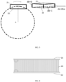
FIG. 1 shows a schematic top view of an inspection apparatus according to an embodiment of the present disclosure. -
FIG. 2 shows a schematic perspective view of a heat dissipation structure according to an embodiment of the present disclosure. -
FIG. 3 shows a schematic view of a movement of a heat dissipation structure according to an embodiment of the present disclosure, wherein a schematic diagram at an upper right portion shows a schematic diagram of air entering a radiator. -
FIG. 4 shows a schematic diagram of a radiator according to an embodiment of the present disclosure. -
FIG. 5 shows a schematic diagram of a radiator according to an embodiment of the present disclosure. -
FIG. 6 shows a schematic diagram of a radiator according to an embodiment of the present disclosure. - In the following embodiments, terms "first", "second", and the like are used to distinguish different components, rather than sequencing or indicating primary or secondary. Terms "upper", "lower", and the like indicating orientations in the specification do not indicate an absolute orientation, but indicate a relative position between components.
- As shown in
FIG. 1 , the embodiments of the present disclosure provide a heat dissipation structure including a supportingframe 50, and the supporting frame is used to rotate around a central axis O of the supporting frame. The supportingframe 50 shown inFIG. 1 is generally cylindrical in shape, defining a circular channel penetrating the supportingframe 50. The supportingframe 50 may carry a measuring tool or a processing tool, as well as devices such as aradiator 30, a motor and the like. The supportingframe 50 is rotatable for operation of the tool carried thereon. In an embodiment, the supportingframe 50 is a ring. In another embodiment, the supportingframe 50 may be a frame having another shape. - In an embodiment, the heat dissipation structure includes a
heat source 40 arranged on the supportingframe 50 and rotating with the supportingframe 50. Theheat source 40 may be the measuring tool or the processing tool. For example, theheat source 40 may be a ray source. The ray source may emit a ray which may generate a large amount of heat during operation, and thus a heat dissipation is required. Theheat source 40 may be aheat source 40 of another type, which is mounted on a part of the supportingframe 50. - In an embodiment, the heat dissipation structure includes a
radiator 30 configured to receive a fluid heated by theheat source 40 from theheat source 40 and input the cooled fluid to theheat source 40. Using theradiator 30 for the fluid is advantageous, which allows the fluid to circulate between the heat source and theradiator 30 so as to transfer the heat generated by the heat source to theradiator 30. At the same time, theradiator 30 may be separated from theheat source 40, so that an arrangement of the apparatus is more flexible. The circulation of the fluid may be realized through a heat pipe, which is included inside theheat source 40 and theradiator 30, and the fluid flows in the heat pipe. Optionally, the circulation may be achieved by apump 31 driving the fluid to flow inside the heat pipe inside the heat source and theradiator 30. The heat pipe may be a metal pipe, a ceramic pipe or a pipe formed by other heat conductive materials. In the embodiment shown inFIG. 1 , thepump 31 is arranged to allow the fluid in the heat pipe to pass through thepump 31, and thepump 31 drives the fluid to flow. Specifically, thepump 31 is configured to pump the fluid out of theheat source 40 and pump the fluid into theradiator 30 so that the fluid circulates between theheat source 40 and theradiator 30. In an embodiment, the heat dissipation structure further includes a container configured to be in fluid connection with theheat source 40 and capable of storing the fluid pumped from theheat source 40. The fluid in the container flows into the radiator for cooling under an action of the pump. For example, under the action of thepump 31, the fluid heated by the heat source first flows into a container such as awater tank 32 and then flows into theradiator 30, the fluid flows back to the heat source after cooling. In an embodiment, thepump 31 may be fixed on thewater tank 32, so that a structure is more compact. Thewater tank 32 may make the fluid flow more uniformly in the heat pipe, and an impact brought by the pump may be buffered. In other embodiments, thepump 31 may be located in another location or may be arranged separately from thewater tank 32. In other embodiments, the container may be a glass container or the like. In an embodiment, the fluid used for heat dissipation is water, aqueous solution, oil or other liquids. - In an embodiment, the
radiator 30 is arranged on a periphery of the supportingframe 50 relative to the central axis O, and theradiator 30 allows air to enter into theradiator 30 via an air inlet opening 30-1 of theradiator 30 and allows the air to be expelled from theradiator 30 via an air outlet opening 30-O of theradiator 30 when the supportingframe 50 rotates around the central axis O of the supportingframe 50.FIG. 3 shows a schematic diagram of theradiator 30 moving in a circle with the supportingframe 50. As shown inFIG. 3 , it is advantageous for theradiator 30 to be arranged on the periphery of the supportingframe 50 relative to the central axis O. In this way, when the supportingframe 50 rotates, theradiator 30 has a maximum linear velocity, and a relative linear velocity of air entering the air inlet opening 30-I (that is, the linear velocity relative to the radiator 30) may be relatively large, thus allowing the air to take the heat of theradiator 30 away. It should be understood here that the supportingframe 50 is not necessarily circular. Even if the supportingframe 50 is provided as another shape due to functional requirements, the "periphery" of the supportingframe 50 may indicate that a position of theradiator 30 allows theradiator 30 to have a greater linear velocity than other parts of the supportingframe 50 when the supportingframe 50 rotates. In an embodiment, the supportingframe 50 may have a ring shape, or the supportingframe 50 may have a cylinder shape or the like. - As shown in
FIG. 1 to FIG. 3 , theradiator 30 may have a shape of a cuboid. One end of theradiator 30 is the air inlet opening 30-I, and the other end of theradiator 30 is the air outlet opening 30-O. The air passes through a path between the air inlet opening 30-I and the air outlet opening 30-O to taking away the heat of theradiator 30 to achieve a purpose of cooling. Theradiator 30 may have other shapes. Theradiator 30 may be composed of afirst plate 21 and asecond plate 22 via a connecting plate. For example, there may be two connecting plates, so that thefirst plate 21, thesecond plate 22 and the two connecting plates together form a box structure, or a structure defining an internal channel. It should be understood that thefirst plate 21, thesecond plate 22 and the connecting plate may form a variety of forms. The connecting plate, thefirst plate 21 and thesecond plate 22 form the box structure, defining the air inlet opening 30-I, the air outlet opening 30-O and a gas path between the air inlet opening 30-I and the air outlet opening 30-O. - In the embodiment shown in
FIG. 2 , an area of thefirst plate 21 is not equal to an area of thesecond plate 22. Such arrangement may make the shape of theradiator 30 conform to the shape of the supportingframe 50, and thefirst plate 21 will not protrude outside the periphery of the supportingframe 50, making an overall structure of the supportingframe 50 compact. It should be known that this is not necessary. Thefirst plate 21 and thesecond plate 22 may have equal area or shape, and the area of thefirst plate 21 may even be larger than the area of thesecond plate 22, so that a flow of air entering theradiator 30 is further improved. - In an embodiment, the
radiator 30 includes thefirst plate 21 and thesecond plate 22 arranged opposite each other, and the air is allowed to pass between thefirst plate 21 and thesecond plate 22 so as to transfer the heat on thefirst plate 21 and thesecond plate 22. On the supportingframe 50, thefirst plate 21 is farther away from the central axis O than thesecond plate 22, or thefirst plate 21 is located on an outer side of the supportingframe 50 away from the center, and thesecond plate 22 is located on an inner side of the supportingframe 50 close to the center. Thefirst plate 21 and thesecond plate 22 may be parallel, however, this is not necessary. - In an embodiment, the
radiator 30 includes the heat pipe arranged in thefirst plate 21 and thesecond plate 22, and the fluid flows through the heat pipe. The heat pipe transfers the heat of the liquid flowing therein to thefirst plate 21 and thesecond plate 22. The heat pipe may be distributed in at least one of thefirst plate 21 and thesecond plate 22, for example, extending meanderingly in at least one of thefirst plate 21 and thesecond plate 22, so that the heat pipe as long as possible may extend in thefirst plate 21 and/or thesecond plate 22 to achieve more sufficient heat transfer. -
FIG. 2 shows a part of the heat pipe. As shown inFIG. 2 , the fluid may enter thefirst plate 21 from aheat pipe inlet 11 of thefirst plate 21, and enter thesecond plate 22 through aheat pipe portion 13 connected between thefirst plate 21 and thesecond plate 22. After circulating in thesecond plate 22, the fluid may be discharged from thesecond plate 22 through aheat pipe outlet 12, and then the cooled fluid may enter the heat source. - In an embodiment, the
first plate 21, thesecond plate 22 and the heat pipe may be formed of a metal pipe, a ceramic pipe or pipes of other materials. The heat pipe in thefirst plate 21 and thesecond plate 22 may be omitted. For example, a pipeline may be formed inside thefirst plate 21 and thesecond plate 22. It is only required for the heat pipe to connect thefirst plate 21 and thesecond plate 22 outside thefirst plate 21 and thesecond plate 22, thus allowing the liquid to flow from theheat source 40 into thefirst plate 21 and thesecond plate 22 through the heat pipe. Thefirst plate 21 and thesecond plate 22 are connected by the heat pipe. - In an embodiment, as shown in
FIG. 4 to FIG. 6 , theradiator 30 includes a plurality of heat sinks 23. The plurality of heat sinks are connected between thefirst plate 21 and thesecond plate 22, and are spaced apart from each other, so that twoadjacent heat sinks 23 between thefirst plate 21 and thesecond plate 22 define a channel that allows air to flow. Theheat sink 23 may be connected to thefirst plate 21 and thesecond plate 22 by, for example, welding. Theheat sink 23 may be a metal sheet such as aluminum, copper, steel, or a sheet or plate formed by other heat conductive materials such as a ceramic sheet. Two ends of theheat sink 23 are respectively connected to thefirst plate 21 and thesecond plate 22. The heat sinks 23 are spaced apart from each other, so that a small channel having openings at two ends is formed between thefirst plate 21, thesecond plate 22 and the adjacent heat sinks 23. The plurality ofheat sinks 23 between thefirst plate 21 and thesecond plate 22 form a plurality of small channels between thefirst plate 21 and thesecond plate 22. The small channel here is relative to the channel of theradiator 30, that is, the channel between the air inlet opening 30-I and the air outlet opening 30-O and between thefirst plate 21 and thesecond plate 22 of theradiator 30 are constituted by the plurality of small channels among the heat sinks 23. Hereinafter, the small channel is referred to as a sub channel. It should be understood that the channel and the sub channel have an inclusion relationship. The channel has a guiding effect on the air, and the sub channel also has a guiding effect on the air. - In an embodiment, as shown in
FIG. 4 , the plurality ofheat sinks 23 are arranged between thefirst plate 21 and thesecond plate 22 in parallel. However, this is not necessary. The plurality ofheat sinks 23 being arranged in parallel with each other may make a manufacturing process simple, and the heat on the heat sinks 23 may be taken away when the air passes through a gap between the heat sinks 23, thus realizing the cooling of theradiator 30. In the embodiment, since theradiator 30 rotates with the supportingframe 50, and theradiator 30 has a linear velocity relative to the air, there is no need to provide a cooling fan, and theradiator 30 may also effectively exchange the heat with the air, achieving a simple structure and good cooling effect. - In an embodiment, the plurality of
heat sinks 23 are arranged to extend between thefirst plate 21 and thesecond plate 22, and each of the plurality ofheat sinks 23 is at an angle with respect to a tangent direction of a circumferential trajectory when the plurality ofheat sinks 23 rotate around the central axis O. As shown inFIG. 5, FIG. 5 is a top view of the radiator 30 (viewed from thefirst plate 21 toward the second plate 22). The tangent direction of the circumferential trajectory may be seen to be close to an air inlet direction shown inFIG. 5 , while an extension direction of theheat sink 23 is inclined relative to the air inlet direction. Since theheat sink 23 is at an angle relative to the air inlet direction, the air entering theradiator 30 is blocked by theheat sink 23 and flows along a surface of theheat sink 23, and a certain pressure is generated between theheat sink 23 and the air, thereby increasing a heat exchange effect between theheat sink 23 and the air. Furthermore, since a length of theheat sink 23 increases after being inclined, a contact area of the heat sink with the air increases. Theheat sink 23 shown inFIG. 5 inclines toward right, and it should be known that theheat sink 23 may incline toward left. In another embodiment, the heat sinks 23 may not be parallel to each other. In a rotating process of theradiator 30 inFIG. 5 , an inclined arrangement of theheat sink 23 produces a whirlwind effect, greatly improving the heat dissipation effect. - In an embodiment, as shown in
FIG. 6, FIG. 6 shows a top view of the radiator 30 (viewed from thefirst plate 21 toward the second plate 22). In theradiator 30 shown inFIG. 6 , each of the plurality ofheat sinks 23 is arranged to extend meanderingly from the air inlet opening 30-I toward the air outlet opening 30-O between thefirst plate 21 and thesecond plate 22, or each of the plurality ofheat sinks 23 is arranged to extend meanderingly on a circumferential trajectory when plurality ofheat sinks 23 rotate around the central axis O. Different from the arrangement of theheat sink 23 inFIG. 4 , since theheat sink 23 is not arranged parallel to the air inlet direction, a transmission direction of the air is changed by theheat sink 23 after the air entering theradiator 30, so that a force is generated between the air and theheat sink 23, the air forms a turbulence flow in the sub channel between the heat sinks 23, thus a heat exchange between the air and theheat sink 23 is strengthened, and the heat dissipation effect of theradiator 30 is improved. It should be understood that theheat sink 23 may have other meandering forms. Here, the meandering represents a non-linear shape of theheat sink 23. - In an embodiment, the plurality of
heat sinks 23 may extend meanderingly from an air inlet to an exhaust outlet, and each of the plurality ofheat sinks 23 may be arranged to extend meanderingly from thefirst plate 21 to thesecond plate 22 in a radial direction relative to the central axis O. In the embodiment, the air forms the turbulence flow in the sub channel between the heat sinks 23, thereby further improving the heat transfer effect between the air and the heat sink. - An aspect of the present disclosure provides an inspection apparatus including the above-mentioned heat dissipation structure. In the embodiment, the
heat source 40 is a ray source arranged on the supportingframe 50 to emit a ray. The supportingframe 50 defines an inspection channel passing the central axis of the supporting frame. In practical applications, an inspected object passes through the inspection channel defined by the supportingframe 50, and ray source emits rays as shown inFIG. 1 . Structure and composition information of the object may be obtained by detecting the rays penetrating the inspected object. The inspection apparatus may further include a detector. - During inspection, the inspection apparatus may control the supporting
frame 50 to rotate at a predetermined speed while the ray source emits rays, thereby being capable of emitting rays toward the object ay a plurality of angles, ray signals penetrating the object is collected and a three-dimensional image of the object is reconstructed by a computer. The inspection apparatus may be a CT inspection apparatus. - Without departing from the scope of the appended claims, those of ordinary skill in the art may conceive other assemblies, devices and features thereof. In particular, it should be noted that, as will be understood by those skilled in the art, one or more features included in one or more drawings may be integrated into the device shown in another drawing. It should be understood that the detailed descriptions and specific examples are only given by way of illustration, and various changes and modifications within the spirit and the scope of the present disclosure will become apparent to those skilled in the art through the descriptions.
Claims (15)
- A heat dissipation structure, comprising:a supporting frame (50) configured to rotate around a central axis (O) of the supporting frame;a heat source (40) arranged on the supporting frame (50) and configured to rotate with the supporting frame (50); anda radiator (30) configured to receive from the heat source (40) a fluid heated by the heat source (40) and input the cooled fluid to the heat source (40);wherein the radiator (30) is arranged on a periphery of the supporting frame (50) relative to the central axis (O), and when the supporting frame rotates around the central axis (O) of the supporting frame, the radiator is configured to allow air to enter into the radiator (30) via an air inlet opening (30-I) of the radiator (30) and to be expelled from the radiator (30) via an air outlet opening (30-O) of the radiator (30) .
- The heat dissipation structure according to claim 1, wherein the radiator (30) comprises a first plate (21) and a second plate (22), the first plate (21) and the second plate (22) are opposite each other to allow the air to pass between the first plate (21) and the second plate (22) so as to remove heat from the first plate (21) and the second plate (22), and the first plate (21) is farther away from the central axis (O) than the second plate (22).
- The heat dissipation structure according to claim 2, wherein the radiator (30) comprises a heat pipe arranged in the first plate (21) and the second plate (22), and the fluid flows through the heat pipe.
- The heat dissipation structure according to claim 2, wherein the radiator (30) comprises a plurality of heat sinks (23), and the plurality of heat sinks (23) are connected between the first plate (21) and the second plate (22) and are spaced apart from each other, so that two adjacent heat sinks (23) between the first plate (21) and the second plate (22) define a channel allowing the air to flow.
- The heat dissipation structure according to claim 4, wherein the plurality of heat sinks (23) are arranged between the first plate (21) and the second plate (22) in parallel.
- The heat dissipation structure according to claim 4, wherein the plurality of heat sinks (23) are arranged to extend between the first plate (21) and the second plate (22), and each of the plurality of heat sinks (23) is at an angle with respect to a tangent direction of a circumferential trajectory of the plurality of heat sinks (23) when the plurality of heat sinks (23) rotate around the central axis (O).
- The heat dissipation structure according to claim 4, wherein each of the plurality of heat sinks (23) is arranged to extend meanderingly from the air inlet opening (30-I) to the air outlet opening (30-O) and between the first plate (21) and the second plate (22).
- The heat dissipation structure according to claim 4, wherein each of the plurality of heat sinks (23) is arranged to extend meanderingly in a radial direction relative to the central axis (O) between the first plate (21) and the second plate (22).
- The heat dissipation structure according to claim 3, wherein the radiator (30) further comprises at least one connecting plate fixedly connected between the first plate (21) and the second plate (22).
- The heat dissipation structure according to claim 9, wherein the at least one connecting plate, the first plate (21) and the second plate (22) form a box structure, the box structure defining the air inlet opening (30-I), the air outlet opening (30-O) and a gas path between the air inlet opening (30-I) and the air outlet opening (30-O).
- The heat dissipation structure according to claim 2, wherein an area of the first plate (21) is not equal to an area of the second plate (22).
- The heat dissipation structure according to claim 1, further comprising a pump (31) configured to pump the fluid out of the heat source (40) and pump the fluid into the radiator (30), so that the fluid circulates between the heat source (40) and the radiator (30);
wherein the heat dissipation structure further comprises a container configured to be in fluid connection with the heat source (40), and the container is capable of storing the fluid pumped out of the heat source (40). - The heat dissipation structure according to claim 1, wherein the fluid is water or oil.
- An inspection apparatus, comprising the heat dissipation structure according to any one of the preceding claims, wherein the heat source (40) is a ray source arranged on the supporting frame (50) to emit rays;
wherein the supporting frame (50) is configured to define an inspection channel passing the central axis (O) of the supporting frame (50). - The inspection apparatus according to claim 14, wherein the ray source (40) is carried by the supporting frame (50) to rotate around the inspection channel, and when the ray source (40) rotates, the ray source (40) is configured to emit rays toward an inspected object to acquire a three-dimensional image of the inspected object.
Applications Claiming Priority (1)
| Application Number | Priority Date | Filing Date | Title |
|---|---|---|---|
| CN202111681959.2A CN114324424A (en) | 2021-12-31 | 2021-12-31 | Heat radiation structure and inspection apparatus |
Publications (2)
| Publication Number | Publication Date |
|---|---|
| EP4206746A1 true EP4206746A1 (en) | 2023-07-05 |
| EP4206746B1 EP4206746B1 (en) | 2025-11-05 |
Family
ID=81023211
Family Applications (1)
| Application Number | Title | Priority Date | Filing Date |
|---|---|---|---|
| EP22217362.7A Active EP4206746B1 (en) | 2021-12-31 | 2022-12-30 | Heat dissipation structure and inspection apparatus |
Country Status (6)
| Country | Link |
|---|---|
| US (1) | US12702371B2 (en) |
| EP (1) | EP4206746B1 (en) |
| JP (1) | JP7433407B2 (en) |
| KR (1) | KR102949086B1 (en) |
| CN (1) | CN114324424A (en) |
| WO (1) | WO2023125292A1 (en) |
Families Citing this family (1)
| Publication number | Priority date | Publication date | Assignee | Title |
|---|---|---|---|---|
| CN114324424A (en) | 2021-12-31 | 2022-04-12 | 同方威视技术股份有限公司 | Heat radiation structure and inspection apparatus |
Citations (4)
| Publication number | Priority date | Publication date | Assignee | Title |
|---|---|---|---|---|
| EP0030072A2 (en) * | 1979-11-30 | 1981-06-10 | Nippondenso Co., Ltd. | Heat exchanger and method of fabricating it |
| US20050089146A1 (en) * | 2003-10-27 | 2005-04-28 | Toth Thomas L. | Method and apparatus of radiographic imaging with an energy beam tailored for a subject to be scanned |
| US20060140345A1 (en) * | 2004-12-29 | 2006-06-29 | Brad Canfield | Modular cooling unit for x-ray device |
| US20190000406A1 (en) * | 2017-06-30 | 2019-01-03 | Shanghai United Imaging Healthcare Co., Ltd. | System and method for pet imaging |
Family Cites Families (17)
| Publication number | Priority date | Publication date | Assignee | Title |
|---|---|---|---|---|
| GB1536427A (en) * | 1975-03-21 | 1978-12-20 | Emi Ltd | Connection arrangement for scanning x-ray machine |
| JP3403790B2 (en) * | 1994-01-10 | 2003-05-06 | 株式会社東芝 | X-ray CT system |
| JP4564144B2 (en) * | 1999-08-30 | 2010-10-20 | 株式会社東芝 | X-ray computer tomography equipment |
| US6491428B1 (en) | 1999-08-30 | 2002-12-10 | Kabushiki Kaisha Toshiba | X-ray computed tomography apparatus |
| JP2002345804A (en) * | 2001-05-18 | 2002-12-03 | Ge Medical Systems Global Technology Co Llc | X-ray tube unit and apparatus, cooling method and program therefor |
| JP2006204399A (en) * | 2005-01-26 | 2006-08-10 | Hitachi Medical Corp | X-ray ct apparatus |
| CN101219056B (en) * | 2007-01-11 | 2011-02-16 | 上海西门子医疗器械有限公司 | Oil cooling heat sinking method and device for computer dislocation scanning imagery equipment |
| CN103732145B (en) * | 2011-08-05 | 2016-08-17 | 东芝电子管器件株式会社 | Cooler, X ray computer tomography device and the maintenance method of X ray computer tomography device |
| JP5931379B2 (en) * | 2011-09-09 | 2016-06-08 | 株式会社東芝 | X-ray computed tomography system |
| JP6104689B2 (en) * | 2013-04-18 | 2017-03-29 | 東芝電子管デバイス株式会社 | X-ray tube apparatus and X-ray computed tomography apparatus |
| US10390778B2 (en) * | 2015-10-19 | 2019-08-27 | Canon Medical Systems Corporation | Gantry |
| JP2019180927A (en) * | 2018-04-12 | 2019-10-24 | キヤノン電子管デバイス株式会社 | Cooling device |
| JP7182400B2 (en) | 2018-08-23 | 2022-12-02 | キヤノンメディカルシステムズ株式会社 | X-ray CT device |
| JP7493944B2 (en) | 2020-01-21 | 2024-06-03 | キヤノンメディカルシステムズ株式会社 | X-ray CT scanner |
| JP2021142145A (en) | 2020-03-12 | 2021-09-24 | キヤノンメディカルシステムズ株式会社 | X-ray computer tomographic apparatus |
| CN114324424A (en) | 2021-12-31 | 2022-04-12 | 同方威视技术股份有限公司 | Heat radiation structure and inspection apparatus |
| CN216792076U (en) * | 2021-12-31 | 2022-06-21 | 同方威视技术股份有限公司 | Heat dissipation structure and inspection equipment |
-
2021
- 2021-12-31 CN CN202111681959.2A patent/CN114324424A/en active Pending
-
2022
- 2022-12-23 US US18/718,509 patent/US12702371B2/en active Active
- 2022-12-23 WO PCT/CN2022/141437 patent/WO2023125292A1/en not_active Ceased
- 2022-12-27 JP JP2022210467A patent/JP7433407B2/en active Active
- 2022-12-28 KR KR1020220187488A patent/KR102949086B1/en active Active
- 2022-12-30 EP EP22217362.7A patent/EP4206746B1/en active Active
Patent Citations (4)
| Publication number | Priority date | Publication date | Assignee | Title |
|---|---|---|---|---|
| EP0030072A2 (en) * | 1979-11-30 | 1981-06-10 | Nippondenso Co., Ltd. | Heat exchanger and method of fabricating it |
| US20050089146A1 (en) * | 2003-10-27 | 2005-04-28 | Toth Thomas L. | Method and apparatus of radiographic imaging with an energy beam tailored for a subject to be scanned |
| US20060140345A1 (en) * | 2004-12-29 | 2006-06-29 | Brad Canfield | Modular cooling unit for x-ray device |
| US20190000406A1 (en) * | 2017-06-30 | 2019-01-03 | Shanghai United Imaging Healthcare Co., Ltd. | System and method for pet imaging |
Also Published As
| Publication number | Publication date |
|---|---|
| JP7433407B2 (en) | 2024-02-19 |
| CN114324424A (en) | 2022-04-12 |
| KR20230104016A (en) | 2023-07-07 |
| JP2023099516A (en) | 2023-07-13 |
| US20250040900A1 (en) | 2025-02-06 |
| KR102949086B1 (en) | 2026-04-07 |
| EP4206746B1 (en) | 2025-11-05 |
| US12702371B2 (en) | 2026-08-11 |
| WO2023125292A1 (en) | 2023-07-06 |
Similar Documents
| Publication | Publication Date | Title |
|---|---|---|
| US5610968A (en) | High capacity cooling system for CT gantry | |
| US9801313B2 (en) | Underwater container cooling via integrated heat exchanger | |
| US20200025641A1 (en) | Leak-detachable liquid-heat-transmission device | |
| CN110268217A (en) | Liquid cooling systems for heat generating equipment | |
| TWI803336B (en) | Heat dissipation device | |
| EP4206746B1 (en) | Heat dissipation structure and inspection apparatus | |
| CN107949713B (en) | Vertical bearing device | |
| KR20160137292A (en) | The Cooling Fan cooled by Cooling Effect of its Surface of the Spindle Fan Blade | |
| CN211151148U (en) | Power distribution and energy management equipment | |
| CN216792076U (en) | Heat dissipation structure and inspection equipment | |
| CN1783463A (en) | Semiconductor chip heat transfer device | |
| CN101219056A (en) | Oil cooling heat sinking method and device for computer dislocation scanning imagery equipment | |
| CN108087292A (en) | A kind of water pump of resistance to idle running with circulating cooling system | |
| CN114650701A (en) | Data center cooling system and underwater data center | |
| CN210832746U (en) | Cooling device for medicament blending | |
| CN117255467A (en) | An integrated strong cooling X-ray flaw detector | |
| CN103705254B (en) | The refrigerating unit of computer X-ray computed tomography scanning instrument stand | |
| CN216747496U (en) | CT examination apparatus | |
| CN216858249U (en) | Machining spindle for five-axis machining center | |
| CN213403938U (en) | Non-contact liquid cooling system for inertial navigation equipment | |
| CN214223537U (en) | Flow guide ring and medical linear accelerator cooling system | |
| CN220383434U (en) | A high-precision deep-sea depth detection device | |
| CN114530305A (en) | Cooling and heat-dissipating system for mining transformer | |
| CN210486618U (en) | Cooler with reaction sensitive type emptying valve | |
| CN212177393U (en) | Waste heat collecting system for high-temperature pump equipment |
Legal Events
| Date | Code | Title | Description |
|---|---|---|---|
| PUAI | Public reference made under article 153(3) epc to a published international application that has entered the european phase |
Free format text: ORIGINAL CODE: 0009012 |
|
| STAA | Information on the status of an ep patent application or granted ep patent |
Free format text: STATUS: REQUEST FOR EXAMINATION WAS MADE |
|
| 17P | Request for examination filed |
Effective date: 20221230 |
|
| AK | Designated contracting states |
Kind code of ref document: A1 Designated state(s): AL AT BE BG CH CY CZ DE DK EE ES FI FR GB GR HR HU IE IS IT LI LT LU LV MC ME MK MT NL NO PL PT RO RS SE SI SK SM TR |
|
| STAA | Information on the status of an ep patent application or granted ep patent |
Free format text: STATUS: EXAMINATION IS IN PROGRESS |
|
| 17Q | First examination report despatched |
Effective date: 20250512 |
|
| GRAP | Despatch of communication of intention to grant a patent |
Free format text: ORIGINAL CODE: EPIDOSNIGR1 |
|
| STAA | Information on the status of an ep patent application or granted ep patent |
Free format text: STATUS: GRANT OF PATENT IS INTENDED |
|
| INTG | Intention to grant announced |
Effective date: 20250722 |
|
| GRAS | Grant fee paid |
Free format text: ORIGINAL CODE: EPIDOSNIGR3 |
|
| GRAA | (expected) grant |
Free format text: ORIGINAL CODE: 0009210 |
|
| STAA | Information on the status of an ep patent application or granted ep patent |
Free format text: STATUS: THE PATENT HAS BEEN GRANTED |
|
| AK | Designated contracting states |
Kind code of ref document: B1 Designated state(s): AL AT BE BG CH CY CZ DE DK EE ES FI FR GB GR HR HU IE IS IT LI LT LU LV MC ME MK MT NL NO PL PT RO RS SE SI SK SM TR |
|
| REG | Reference to a national code |
Ref country code: CH Ref legal event code: F10 Free format text: ST27 STATUS EVENT CODE: U-0-0-F10-F00 (AS PROVIDED BY THE NATIONAL OFFICE) Effective date: 20251105 Ref country code: GB Ref legal event code: FG4D |
|
| REG | Reference to a national code |
Ref country code: DE Ref legal event code: R096 Ref document number: 602022024359 Country of ref document: DE |
|
| REG | Reference to a national code |
Ref country code: IE Ref legal event code: FG4D |
|
| PGFP | Annual fee paid to national office [announced via postgrant information from national office to epo] |
Ref country code: AT Payment date: 20260113 Year of fee payment: 4 |
|
| PGFP | Annual fee paid to national office [announced via postgrant information from national office to epo] |
Ref country code: FR Payment date: 20251125 Year of fee payment: 4 |
|
| REG | Reference to a national code |
Ref country code: NL Ref legal event code: MP Effective date: 20251105 |
|
| PG25 | Lapsed in a contracting state [announced via postgrant information from national office to epo] |
Ref country code: ES Free format text: LAPSE BECAUSE OF FAILURE TO SUBMIT A TRANSLATION OF THE DESCRIPTION OR TO PAY THE FEE WITHIN THE PRESCRIBED TIME-LIMIT Effective date: 20251105 |
|
| REG | Reference to a national code |
Ref country code: LT Ref legal event code: MG9D |
|
| PG25 | Lapsed in a contracting state [announced via postgrant information from national office to epo] |
Ref country code: NO Free format text: LAPSE BECAUSE OF FAILURE TO SUBMIT A TRANSLATION OF THE DESCRIPTION OR TO PAY THE FEE WITHIN THE PRESCRIBED TIME-LIMIT Effective date: 20260205 |
|
| PG25 | Lapsed in a contracting state [announced via postgrant information from national office to epo] |
Ref country code: AT Free format text: LAPSE BECAUSE OF FAILURE TO SUBMIT A TRANSLATION OF THE DESCRIPTION OR TO PAY THE FEE WITHIN THE PRESCRIBED TIME-LIMIT Effective date: 20251105 Ref country code: HR Free format text: LAPSE BECAUSE OF FAILURE TO SUBMIT A TRANSLATION OF THE DESCRIPTION OR TO PAY THE FEE WITHIN THE PRESCRIBED TIME-LIMIT Effective date: 20251105 Ref country code: FI Free format text: LAPSE BECAUSE OF FAILURE TO SUBMIT A TRANSLATION OF THE DESCRIPTION OR TO PAY THE FEE WITHIN THE PRESCRIBED TIME-LIMIT Effective date: 20251105 |
|
| REG | Reference to a national code |
Ref country code: AT Ref legal event code: MK05 Ref document number: 1854942 Country of ref document: AT Kind code of ref document: T Effective date: 20251105 |
|
| PG25 | Lapsed in a contracting state [announced via postgrant information from national office to epo] |
Ref country code: NL Free format text: LAPSE BECAUSE OF FAILURE TO SUBMIT A TRANSLATION OF THE DESCRIPTION OR TO PAY THE FEE WITHIN THE PRESCRIBED TIME-LIMIT Effective date: 20251105 |
|
| PG25 | Lapsed in a contracting state [announced via postgrant information from national office to epo] |
Ref country code: RS Free format text: LAPSE BECAUSE OF FAILURE TO SUBMIT A TRANSLATION OF THE DESCRIPTION OR TO PAY THE FEE WITHIN THE PRESCRIBED TIME-LIMIT Effective date: 20260205 |
|
| PG25 | Lapsed in a contracting state [announced via postgrant information from national office to epo] |
Ref country code: IS Free format text: LAPSE BECAUSE OF FAILURE TO SUBMIT A TRANSLATION OF THE DESCRIPTION OR TO PAY THE FEE WITHIN THE PRESCRIBED TIME-LIMIT Effective date: 20260305 |
|
| PG25 | Lapsed in a contracting state [announced via postgrant information from national office to epo] |
Ref country code: PT Free format text: LAPSE BECAUSE OF FAILURE TO SUBMIT A TRANSLATION OF THE DESCRIPTION OR TO PAY THE FEE WITHIN THE PRESCRIBED TIME-LIMIT Effective date: 20260305 |
|
| PG25 | Lapsed in a contracting state [announced via postgrant information from national office to epo] |
Ref country code: PL Free format text: LAPSE BECAUSE OF FAILURE TO SUBMIT A TRANSLATION OF THE DESCRIPTION OR TO PAY THE FEE WITHIN THE PRESCRIBED TIME-LIMIT Effective date: 20251105 |
|
| PG25 | Lapsed in a contracting state [announced via postgrant information from national office to epo] |
Ref country code: LV Free format text: LAPSE BECAUSE OF FAILURE TO SUBMIT A TRANSLATION OF THE DESCRIPTION OR TO PAY THE FEE WITHIN THE PRESCRIBED TIME-LIMIT Effective date: 20251105 |
|
| PG25 | Lapsed in a contracting state [announced via postgrant information from national office to epo] |
Ref country code: BG Free format text: LAPSE BECAUSE OF FAILURE TO SUBMIT A TRANSLATION OF THE DESCRIPTION OR TO PAY THE FEE WITHIN THE PRESCRIBED TIME-LIMIT Effective date: 20251105 |
|
| PG25 | Lapsed in a contracting state [announced via postgrant information from national office to epo] |
Ref country code: RO Free format text: LAPSE BECAUSE OF FAILURE TO SUBMIT A TRANSLATION OF THE DESCRIPTION OR TO PAY THE FEE WITHIN THE PRESCRIBED TIME-LIMIT Effective date: 20251105 |
|
| PG25 | Lapsed in a contracting state [announced via postgrant information from national office to epo] |
Ref country code: LT Free format text: LAPSE BECAUSE OF FAILURE TO SUBMIT A TRANSLATION OF THE DESCRIPTION OR TO PAY THE FEE WITHIN THE PRESCRIBED TIME-LIMIT Effective date: 20251105 |
|
| REG | Reference to a national code |
Ref country code: DE Ref legal event code: R119 Ref document number: 602022024359 Country of ref document: DE |
|
| PG25 | Lapsed in a contracting state [announced via postgrant information from national office to epo] |
Ref country code: SM Free format text: LAPSE BECAUSE OF FAILURE TO SUBMIT A TRANSLATION OF THE DESCRIPTION OR TO PAY THE FEE WITHIN THE PRESCRIBED TIME-LIMIT Effective date: 20251105 |
|
| PG25 | Lapsed in a contracting state [announced via postgrant information from national office to epo] |
Ref country code: DK Free format text: LAPSE BECAUSE OF FAILURE TO SUBMIT A TRANSLATION OF THE DESCRIPTION OR TO PAY THE FEE WITHIN THE PRESCRIBED TIME-LIMIT Effective date: 20251105 |
|
| PG25 | Lapsed in a contracting state [announced via postgrant information from national office to epo] |
Ref country code: IT Free format text: LAPSE BECAUSE OF FAILURE TO SUBMIT A TRANSLATION OF THE DESCRIPTION OR TO PAY THE FEE WITHIN THE PRESCRIBED TIME-LIMIT Effective date: 20251105 |
|
| PG25 | Lapsed in a contracting state [announced via postgrant information from national office to epo] |
Ref country code: EE Free format text: LAPSE BECAUSE OF FAILURE TO SUBMIT A TRANSLATION OF THE DESCRIPTION OR TO PAY THE FEE WITHIN THE PRESCRIBED TIME-LIMIT Effective date: 20251105 |
|
| PG25 | Lapsed in a contracting state [announced via postgrant information from national office to epo] |
Ref country code: CZ Free format text: LAPSE BECAUSE OF FAILURE TO SUBMIT A TRANSLATION OF THE DESCRIPTION OR TO PAY THE FEE WITHIN THE PRESCRIBED TIME-LIMIT Effective date: 20251105 |
|
| REG | Reference to a national code |
Ref country code: CH Ref legal event code: H13 Free format text: ST27 STATUS EVENT CODE: U-0-0-H10-H13 (AS PROVIDED BY THE NATIONAL OFFICE) Effective date: 20260723 |
|
| PG25 | Lapsed in a contracting state [announced via postgrant information from national office to epo] |
Ref country code: SK Free format text: LAPSE BECAUSE OF FAILURE TO SUBMIT A TRANSLATION OF THE DESCRIPTION OR TO PAY THE FEE WITHIN THE PRESCRIBED TIME-LIMIT Effective date: 20251105 |
|
| PG25 | Lapsed in a contracting state [announced via postgrant information from national office to epo] |
Ref country code: SE Free format text: LAPSE BECAUSE OF FAILURE TO SUBMIT A TRANSLATION OF THE DESCRIPTION OR TO PAY THE FEE WITHIN THE PRESCRIBED TIME-LIMIT Effective date: 20251105 |
|
| PG25 | Lapsed in a contracting state [announced via postgrant information from national office to epo] |
Ref country code: MC Free format text: LAPSE BECAUSE OF FAILURE TO SUBMIT A TRANSLATION OF THE DESCRIPTION OR TO PAY THE FEE WITHIN THE PRESCRIBED TIME-LIMIT Effective date: 20251105 |