EP4206723A1 - Ranging method and device, storage medium, and lidar - Google Patents
Ranging method and device, storage medium, and lidar Download PDFInfo
- Publication number
- EP4206723A1 EP4206723A1 EP22217102.7A EP22217102A EP4206723A1 EP 4206723 A1 EP4206723 A1 EP 4206723A1 EP 22217102 A EP22217102 A EP 22217102A EP 4206723 A1 EP4206723 A1 EP 4206723A1
- Authority
- EP
- European Patent Office
- Prior art keywords
- view
- light emission
- emission power
- field
- edge field
- Prior art date
- Legal status (The legal status is an assumption and is not a legal conclusion. Google has not performed a legal analysis and makes no representation as to the accuracy of the status listed.)
- Pending
Links
Images


Classifications
-
- G—PHYSICS
- G01—MEASURING; TESTING
- G01S—RADIO DIRECTION-FINDING; RADIO NAVIGATION; DETERMINING DISTANCE OR VELOCITY BY USE OF RADIO WAVES; LOCATING OR PRESENCE-DETECTING BY USE OF THE REFLECTION OR RERADIATION OF RADIO WAVES; ANALOGOUS ARRANGEMENTS USING OTHER WAVES
- G01S17/00—Systems using the reflection or reradiation of electromagnetic waves other than radio waves, e.g. lidar systems
- G01S17/02—Systems using the reflection of electromagnetic waves other than radio waves
- G01S17/06—Systems determining position data of a target
- G01S17/08—Systems determining position data of a target for measuring distance only
- G01S17/10—Systems determining position data of a target for measuring distance only using transmission of interrupted, pulse-modulated waves
-
- G—PHYSICS
- G01—MEASURING; TESTING
- G01S—RADIO DIRECTION-FINDING; RADIO NAVIGATION; DETERMINING DISTANCE OR VELOCITY BY USE OF RADIO WAVES; LOCATING OR PRESENCE-DETECTING BY USE OF THE REFLECTION OR RERADIATION OF RADIO WAVES; ANALOGOUS ARRANGEMENTS USING OTHER WAVES
- G01S7/00—Details of systems according to groups G01S13/00, G01S15/00, G01S17/00
- G01S7/48—Details of systems according to groups G01S13/00, G01S15/00, G01S17/00 of systems according to group G01S17/00
- G01S7/497—Means for monitoring or calibrating
-
- G—PHYSICS
- G01—MEASURING; TESTING
- G01S—RADIO DIRECTION-FINDING; RADIO NAVIGATION; DETERMINING DISTANCE OR VELOCITY BY USE OF RADIO WAVES; LOCATING OR PRESENCE-DETECTING BY USE OF THE REFLECTION OR RERADIATION OF RADIO WAVES; ANALOGOUS ARRANGEMENTS USING OTHER WAVES
- G01S7/00—Details of systems according to groups G01S13/00, G01S15/00, G01S17/00
- G01S7/48—Details of systems according to groups G01S13/00, G01S15/00, G01S17/00 of systems according to group G01S17/00
- G01S7/481—Constructional features, e.g. arrangements of optical elements
- G01S7/4814—Constructional features, e.g. arrangements of optical elements of transmitters alone
- G01S7/4815—Constructional features, e.g. arrangements of optical elements of transmitters alone using multiple transmitters
-
- G—PHYSICS
- G01—MEASURING; TESTING
- G01S—RADIO DIRECTION-FINDING; RADIO NAVIGATION; DETERMINING DISTANCE OR VELOCITY BY USE OF RADIO WAVES; LOCATING OR PRESENCE-DETECTING BY USE OF THE REFLECTION OR RERADIATION OF RADIO WAVES; ANALOGOUS ARRANGEMENTS USING OTHER WAVES
- G01S17/00—Systems using the reflection or reradiation of electromagnetic waves other than radio waves, e.g. lidar systems
- G01S17/02—Systems using the reflection of electromagnetic waves other than radio waves
- G01S17/06—Systems determining position data of a target
-
- G—PHYSICS
- G01—MEASURING; TESTING
- G01S—RADIO DIRECTION-FINDING; RADIO NAVIGATION; DETERMINING DISTANCE OR VELOCITY BY USE OF RADIO WAVES; LOCATING OR PRESENCE-DETECTING BY USE OF THE REFLECTION OR RERADIATION OF RADIO WAVES; ANALOGOUS ARRANGEMENTS USING OTHER WAVES
- G01S17/00—Systems using the reflection or reradiation of electromagnetic waves other than radio waves, e.g. lidar systems
- G01S17/02—Systems using the reflection of electromagnetic waves other than radio waves
- G01S17/06—Systems determining position data of a target
- G01S17/42—Simultaneous measurement of distance and other co-ordinates
-
- G—PHYSICS
- G01—MEASURING; TESTING
- G01S—RADIO DIRECTION-FINDING; RADIO NAVIGATION; DETERMINING DISTANCE OR VELOCITY BY USE OF RADIO WAVES; LOCATING OR PRESENCE-DETECTING BY USE OF THE REFLECTION OR RERADIATION OF RADIO WAVES; ANALOGOUS ARRANGEMENTS USING OTHER WAVES
- G01S7/00—Details of systems according to groups G01S13/00, G01S15/00, G01S17/00
- G01S7/48—Details of systems according to groups G01S13/00, G01S15/00, G01S17/00 of systems according to group G01S17/00
- G01S7/4802—Details of systems according to groups G01S13/00, G01S15/00, G01S17/00 of systems according to group G01S17/00 using analysis of echo signal for target characterisation; Target signature; Target cross-section
-
- G—PHYSICS
- G01—MEASURING; TESTING
- G01S—RADIO DIRECTION-FINDING; RADIO NAVIGATION; DETERMINING DISTANCE OR VELOCITY BY USE OF RADIO WAVES; LOCATING OR PRESENCE-DETECTING BY USE OF THE REFLECTION OR RERADIATION OF RADIO WAVES; ANALOGOUS ARRANGEMENTS USING OTHER WAVES
- G01S7/00—Details of systems according to groups G01S13/00, G01S15/00, G01S17/00
- G01S7/48—Details of systems according to groups G01S13/00, G01S15/00, G01S17/00 of systems according to group G01S17/00
- G01S7/4804—Auxiliary means for detecting or identifying lidar signals or the like, e.g. laser illuminators
-
- G—PHYSICS
- G01—MEASURING; TESTING
- G01S—RADIO DIRECTION-FINDING; RADIO NAVIGATION; DETERMINING DISTANCE OR VELOCITY BY USE OF RADIO WAVES; LOCATING OR PRESENCE-DETECTING BY USE OF THE REFLECTION OR RERADIATION OF RADIO WAVES; ANALOGOUS ARRANGEMENTS USING OTHER WAVES
- G01S7/00—Details of systems according to groups G01S13/00, G01S15/00, G01S17/00
- G01S7/48—Details of systems according to groups G01S13/00, G01S15/00, G01S17/00 of systems according to group G01S17/00
- G01S7/483—Details of pulse systems
- G01S7/484—Transmitters
-
- G—PHYSICS
- G01—MEASURING; TESTING
- G01S—RADIO DIRECTION-FINDING; RADIO NAVIGATION; DETERMINING DISTANCE OR VELOCITY BY USE OF RADIO WAVES; LOCATING OR PRESENCE-DETECTING BY USE OF THE REFLECTION OR RERADIATION OF RADIO WAVES; ANALOGOUS ARRANGEMENTS USING OTHER WAVES
- G01S7/00—Details of systems according to groups G01S13/00, G01S15/00, G01S17/00
- G01S7/48—Details of systems according to groups G01S13/00, G01S15/00, G01S17/00 of systems according to group G01S17/00
- G01S7/483—Details of pulse systems
- G01S7/486—Receivers
- G01S7/4868—Controlling received signal intensity or exposure of sensor
-
- Y—GENERAL TAGGING OF NEW TECHNOLOGICAL DEVELOPMENTS; GENERAL TAGGING OF CROSS-SECTIONAL TECHNOLOGIES SPANNING OVER SEVERAL SECTIONS OF THE IPC; TECHNICAL SUBJECTS COVERED BY FORMER USPC CROSS-REFERENCE ART COLLECTIONS [XRACs] AND DIGESTS
- Y02—TECHNOLOGIES OR APPLICATIONS FOR MITIGATION OR ADAPTATION AGAINST CLIMATE CHANGE
- Y02A—TECHNOLOGIES FOR ADAPTATION TO CLIMATE CHANGE
- Y02A90/00—Technologies having an indirect contribution to adaptation to climate change
- Y02A90/10—Information and communication technologies [ICT] supporting adaptation to climate change, e.g. for weather forecasting or climate simulation
Definitions
- This application relates to the technical field of computers, and in particular, to a ranging method and device, a storage medium, and LiDAR.
- illuminance in an edge field of view is lower than illuminance in a central field of view in an illuminated field of view.
- the larger a detecting angle of view the lower the illuminance in the edge field of view.
- it is necessary to set light vignetting for the edge field of view which aggravates illuminance decline in the edge field of view.
- An embodiment of this application provides a ranging method and device, a storage medium, and LiDAR, to ensure that illuminance in an edge field of view is consistent with illuminance in a central field of view, thereby ensuring that a ranging distance of an edge is consistent with a ranging distance of the central field of view.
- the technical solution is as follows:
- an embodiment of this application provides a ranging method, including the following steps:
- an embodiment of this application provides a ranging device, including:
- an embodiment of this application provides a computer storage medium.
- the computer storage medium has stored thereon a plurality of instructions.
- the instructions are capable of being loaded by a processor to perform the steps of the method described above.
- an embodiment of this application provides a LiDAR, which includes a processor and a storage.
- the storage stores a computer program.
- the computer program is capable of being loaded by a processor to perform the steps of the method described above.
- the edge field of view and the central field of view are determined.
- the light emission power for the edge field of view and the light emission power for the central field of view are acquired.
- the light emission power for the edge field of view is compensated based on the difference between the light emission power for the edge field of view and the light emission power for the central field of view.
- the target object is detected based on the light emission power for the central field of view and the compensated light emission power for the edge field of view. Therefore, illuminance of the edge field of view can be consistent with illuminance of the central field of view, thereby ensuring that a ranging distance of the edge field of view is consistent with a ranging distance of the central field of view.
- a ranging method provided in this embodiment of this application is described in detail with reference to FIG. 1 to FIG. 12 .
- This method can be realized by computer program, and can be operated on a ranging device based on Von Neumann system.
- the computer program can be integrated in applications or operated as an independent tool application.
- the ranging device in this embodiment of this application can be any apparatus adopting the ranging method, including but not limited to: a vehicle-mounted apparatus, an aircraft, a train, a handheld apparatus, a wearable apparatus, a computing apparatus or other processing apparatuses connected to a wireless modem.
- LiDAR includes an emitting module and a receiving module.
- the emitting module can consist of an emitting unit.
- the receiving module can consist of a receiving unit with high sensitivity.
- the LiDAR can include an emitting array.
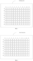
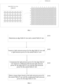
- FIG. 1 is an exemplary schematic diagram of an emitting array.
- One emitting array can include 8 x 12 emitting units.
- LiDAR can include a receiving array.
- FIG. 2 is an exemplary schematic diagram of one receiving array.
- One receiving array can include 8 x 12 receiving units.
- the emitting unit and the receiving unit are one-to-one correspondence.
- the emitting principle of the LiDAR is as follows: the emitting unit emits a laser beam to a measured object.
- the receiving unit corresponding to the emitting unit receives echo signals generated by the emitted laser beam to realize detection of the object.
- the LiDAR can be a mechanical LiDAR or a solid-state LiDAR. This application does not limit a type of the LiDAR.
- the emitting unit can include one laser or a group of lasers. This application does not limit the number of lasers included in each emitting unit. As shown in FIG. 3, FIG. 3 shows an entire field-of-view diagram when one emitting unit includes the plurality of lasers.
- illuminance of the entire field of view is reduced in proportion to a power of four of a cosine of an incident angle ⁇ . Therefore, the larger an angle of view, the lower illuminance of an edge field of view in the entire field of view.
- a vignetting effect is arranged at a laser beam corresponding to the field of view at the edge position. This brings a vignetting phenomenon. That is, the more far away from a central axis, the smaller an effective aperture of an emitted laser beam passing through an optical system. Therefore, the more far away from a central axis, the weaker an intensity of the laser beam is.
- a formed image is vignetted from a part far away from the central axis is formed, which further reduces illuminance of a field of view at an edge. Therefore, there is a difference between illuminance in the field of view at the edge position and illuminance in the field of view at a central position, so that a ranging distance of the field of view at the edge position is inconsistent with a ranging distance of the field of view at the central position. That is, a ranging distance of the central field of view is faulty. For example, for a target object with 30m, 100klux and 10% reflectivity, the ranging distance of the field of view at the edge position and the ranging distance of the field of view at the central position deviates by 16% or more. In order to solve a problem that the illuminance of the edge field of view is inconsistent with the illuminance of the central field of view due to decrease in illuminance of an edge field of view in the prior art, this application provides a ranging method.
- FIG. 4 is a flowchart of a ranging method according to an embodiment of this application.
- the method in this embodiment of this application can include following steps:
- delimitation between the edge field of view and the central field of view is related to LiDAR design parameters.
- the central field of view accounts for 50% of an entire detecting field of view, that is, in a case that a horizontal detecting angle of view is 120 degrees
- the field of view of 60 degrees at a middle is a central field of view in a horizontal direction thereof, which is similar in a vertical direction. That is, in a case that a vertical detecting angle of view is 40 degrees, the field of view of 20 degrees at the middle is a central field of view in a vertical direction thereof.
- the edge field of view can be a field of view at an edge position of an emitting array.
- One edge field of view of the emitting array can be a plurality of symmetrical fields of view.
- FIG. 5 is an exemplary schematic diagram of a central field of view and an edge field of view in an emitting array.
- a field of view corresponding to columns 0 and 1 on a left side and a field of view corresponding to columns 5 and 6 on a right side of the emitting array are divided as an edge field of view.
- Fields of view corresponding to emitting units in columns 2, 3 and 4 at a central position are divided as a central field of view.
- the edge field of view when there are a plurality of edges field of view, the edge field of view can be divided according to a difference between an angle of view corresponding to the edge field of view and the central angle of view.
- a division manner can be to hierarchically divide the edge field of view according to the difference between the angle of view corresponding to the edge field of view and the central angle of view.
- an edge field of view in which an absolute value of a difference between an angle of view corresponding to the edge field of view and an angle of view corresponding to the central field of view is in a first numerical range, can be defined as a first-level edge field of view.
- FIG. 6 is a schematic diagram of the edge field of view in one emitting array according to a difference of a horizontal angle of view in the emitting array.
- the field of view corresponding to left and right sides of the emitting array is divided as the edge field of view.
- the field of view corresponding to the central position is divided as the central field of view.
- the edge field of view is then divided as the first-level edge field of view and the second-level edge field of view.
- FIG. 7 is a schematic diagram of the entire field of view of one emitting array including the plurality of emitting arrays
- the field of view corresponding to the emitting array at the central position is the central field of view.
- the field of view corresponding to the leftmost or rightmost emitting array is the edge field of view.
- the edges field of view is divided according to an absolute value of a difference between an angle of view corresponding to each group of the emitting arrays of the edge field of view and the angle of view corresponding to the central field of view.
- FIG. 8 is a schematic diagram of the entire field of view of one emitting array including the plurality of emitting arrays.
- the edge fields of view on the left and right sides of the central field of view are divided into the first-level edge field of view and the second-level edge field of view.
- a division basis of the edge field of view and the central field of view can be artificially divided according to the corresponding illuminance in the plurality of fields of view.
- the field of view with low illuminance is divided as the edge field of view.
- the field of view with near ideal illuminance is divided as the central field of view.
- a hierarchical strategy mentioned above can also be selected according to a difference between illuminance corresponding to a field of view at the central position and illuminance corresponding to a field of view at an edge position during the use of the LiDAR.
- the light emission power for the edge field of view and the light emission power for the central field of view refer to a power of a laser beam emitting from the edge field of view and the central field of view after passing through an emitting lens.
- the light emission power for the edge field of view and the light emission power for the central field of view are related to design parameters of a LiDAR, and specifically related to a feature of a LiDAR lens and design of horizontal and vertical angles of field of view detected by the LiDAR. It can be understood that the larger the vertical and horizontal angles of field of view of the LiDAR, the greater a difference between the light emission power for the edge field of view and the light emission power for the central field of view.
- the light emission power for the edge field of view and the light emission power for the central field of view can be obtained by directly invoking data stored in Random Access Memory (RAM) calibrated in Field Programmable Gate Array (FPGA) of the LiDAR, or by detecting a detection distance of the central field of view and a detection distance of the edge field of view based on the formula R ⁇ P , where R is the detection distance of the central field of view or the edge field of view, and P is the light emission power for the central field of view or the edge field of view.
- RAM Random Access Memory
- FPGA Field Programmable Gate Array
- the light emission power for the edge field of view is increased until the light emission power corresponding to the edge field of view is consistent with the light emission power corresponding to the central field of view, so that the illuminance corresponding to the edge field of view is consistent with the illuminance of the central field of view, thus ensuring that the ranging distance of the edge field of view is consistent with the ranging distance of the central field of view. If the determined edge field of view is as shown in FIG. 5 , the light emission power for the edge field of view can be compensated according to the difference between the light emission power for the edge field of view and the light emission power for the central field of view.
- edge field of view is divided according to the angle of view corresponding to the edge field of view, it is necessary to calculate the differences between the light emission power for partitions of the edge field of view and the light emission power for the central field of view respectively, and compensate the light emission power for the edge field of view according to the differences between the light emission power for the different partitions of the edge field of view and the light emission power for the central field of view.
- the edge field of view is divided by a division manner shown in FIG. 6
- a difference between light emission power for the first-level edge field of view and the light emission power for the central field of view needs to be calculated.
- the light emission power for the first-level edge field of view is compensated according to a difference between the light emission power for the first-level edge field of view and the light emission power for the central field of view.
- the difference between the light emission power for the second-level edge field of view and the light emission power for the central field of view needs to be calculated.
- the light emission power for the second-level edge field of view is compensated according to a difference between the light emission power for the second-level edge field of view and the light emission power for the central field of view.
- the light emission power for the edge field of view can be increased in the same way or in different ways. Whether the same way or different ways are used to increase the light emission power for the edge field of view, the increased light emission power can be different for different levels of the edge fields of view. For example, as shown in FIG. 6 , the increased light emission power for the first-level edge field of view is less than the increased light emission power for the second-level edge field of view.
- the target object is an object to be ranged by the LiDAR, and can be an arbitrary object.
- the illuminance corresponding to the light emission power for the edge field of view is consistent with the illuminance corresponding to the light emission power for the central field of view. Therefore, when the target object is detected by adopting the light emission power for the central field of view and the compensated light emission power for the edge field of view, a distance between the LiDAR and the target object obtained by the edge field of view is consistent with a distance obtained by the central field of view.
- the edge field of view and the central field of view are determined.
- the light emission power for the edge field of view and the light emission power for the central field of view are acquired.
- the light emission power for the edge field of view is compensated based on the difference between the light emission power for the edge field of view and the light emission power for the central field of view.
- the target object is detected based on the light emission power for the central field of view and the compensated light emission power for the edge field of view.
- FIG. 9 is a flowchart of a ranging method according to an embodiment of this application.
- the light emission power for the edge field of view can be increased by one or more manners of increasing the number of luminous points, an emitting pulse sequence within a preset duration and an emitting power, so that the light emission power for the edge field of view is consistent with the light emission power for the central field of view.
- Specific steps are as follows: S201: Determine an edge field of view and a central field of view.
- the emitting unit group is a hardware device in LiDAR.
- One emitting unit group can include at least one laser and at least one laser receiver.
- the LiDAR can include a plurality of emitting unit groups.
- Acquiring the light emission power for the edge field of view can be acquiring emitting power of a laser in the emitting unit group corresponding to the edge field of view.
- Acquiring the light emission power for the central field of view can be acquiring emitting power of a laser in the emitting unit group corresponding to the central field of view.
- a manner of controlling the emitting parameter of the emitting unit group corresponding to the edge field of view can be as follows: the light emission power for the edge field of view is increased by increasing the number of lasers emitting laser beams in parallel in the emitting unit group corresponding to the edge field of view.
- FIG. 10 is a schematic diagram of an emitting array (the number of emitting units corresponding to an edge field of view in FIG.
- the light emission power for the edge field of view is increased by increasing an emitting pulse sequence within a preset duration of each of the lasers in an emitting unit group corresponding to the edge field of view, and/or, the light emission power for the edge field of view is increased by increasing emitting power of each of the lasers in the emitting unit group corresponding to the edge field of view.
- the number of lasers emitting laser beams in parallel in the emitting unit group corresponding to the edge field of view is proportional to the light emission power for the edge field of view.
- the number of lasers emitting laser beams in parallel in the emitting unit group corresponding to the edge field of view is increased, the light emission power for the edge field of view is increased accordingly.
- the current number of lasers emitting laser beams in parallel in the emitting unit group corresponding to the edge field of view is as follows: after detection, only when there are 16 lasers emitting laser beams in parallel in the emitting unit group corresponding to the edge field of view, if illuminance corresponding to the edge field of view is consistent with illuminance corresponding to the central field of view, the number of lasers emitting laser beams in parallel in the emitting unit group corresponding to the edge field of view is increased from 12 to 16.
- the emitting pulse sequence within the preset duration of each of the lasers in the emitting unit group corresponding to the edge field of view is proportional to the light emission power for the edge field of view.
- the emitting pulse sequence within the preset duration of each of the lasers in the emitting unit group corresponding to the edge field of view is increased, the light emission power for the edge field of view is increased accordingly.
- FIG. 11 is a schematic diagram of an emitting pulse sequence per unit time T before the increase.
- FIG. 12 is a schematic diagram of the emitting pulse sequence per unit time T after the increase.
- the emitting pulse sequence within the preset duration of each of the lasers in the emitting unit group corresponding to the edge field of view can be increased based on the light emission power for the central field of view, so that illuminance corresponding to the light emission power for the edge field of view is consistent with the illuminance corresponding to the central field of view, thereby ensuring that a ranging distance of the edge field of view is consistent with a ranging distance of the central field of view.
- the emitting power of each of the lasers in the emitting unit group corresponding to the edge field of view is proportional to the light emitting power for the edge field of view.
- the emitting power of each of the lasers in the emitting unit group corresponding to the edge field of view is increased, the light emitting power for the edge field of view is increased accordingly.
- the emitting power of each of the lasers in the emitting unit group corresponding to the edge field of view can be increased as follows: the current of the edge field of view is increased. Based on the acquired light emission power for the central field of view, a current of the edge field of view is increased so that the light emission power for the edge field of view is consistent with the light emission power for the central field of view. Of example, the current of the edge field of view is currently 1.0A. After detection, when the current of the edge field of view is 1.2A, the light emission power for the edge field of view is consistent with the light emission power for the central field of view.
- the current of the edge field of view can be increased from 1.0A to 1.2A, so that the light emission power for the edge field of view is consistent with the light emission power for the central field of view, and illuminance of the edge field of view is consistent with illuminance of the central field of view, thereby ensuring that a ranging distance of the edge field of view is consistent with a ranging distance of the central field of view.
- the light emission power for the edge field of view can be increased with a plurality of manners of increasing the number of lasers emitting laser beams in parallel in the emitting unit group corresponding to the edge field of view, the emitting pulse sequence within the preset duration of each of the lasers in the emitting unit group corresponding to the edge field of view, and the emitting power of each of the lasers in the emitting unit group corresponding to the edge field of view.
- the light emission power for the edge field of view is increased by the combination of increasing the number of lasers emitting laser beams in parallel in the emitting unit group corresponding to the edge field of view with increasing the emitting pulse sequence within the preset duration of each of the lasers in the emitting unit group corresponding to the edge field of view.
- the light emission power for the edge field of view is increased by the combination of increasing the number of lasers emitting laser beams in parallel in the emitting unit group corresponding to the edge field of view and by increasing the emitting power of each of the lasers in the emitting unit group corresponding to the edge field of view.
- the light emission power for the edge field of view is increased by the combination of increasing the emitting pulse sequence within the preset duration of each of the lasers in the emitting unit group corresponding to the edge field of view and with the manner of increasing the emitting power of each of the lasers in the emitting unit group corresponding to the edge field of view.
- the light emission power for the edge field of view is increased by the combination of increasing the number of lasers emitting laser beams in parallel in the emitting unit group corresponding to the edge field of view, the emitting pulse sequence within the preset duration of each of the lasers in the emitting unit group corresponding to the edge field of view, and the emitting power of each of the lasers in the emitting unit group corresponding to the edge field of view.
- the light emission power thereof for the same edge field of view, it is possible to increase the light emission power thereof by increasing the number of lasers emitting laser beams in parallel in the corresponding emitting unit group and increasing the emitting pulse sequence within the preset duration of each of the lasers in the corresponding emitting unit group.
- the light emission power for the corresponding edge field of view can be increased in different ways. For example, as shown in FIG. 6 , for the first-level edge field of view, the light emission power thereof is increased with the manner of increasing the number of lasers emitting laser beams in parallel in the emitting unit group corresponding to the edge field of view.
- the light emission power thereof is increased by increasing the emitting pulse sequence within the preset duration of each of the lasers in the emitting unit group corresponding to the edge field of view.
- the edge field of view and the central field of view are determined.
- the light emission power for the edge field of view and the light emission power for the central field of view are acquired.
- the emitting unit group corresponding to the edge field of view and the emitting unit group corresponding to the central field of view are determined.
- the light emission power for the edge field of view is compensated with the manner of increasing an emitting parameter in the emitting unit group corresponding to the edge field of view.
- the target object is detected based on the light emission power for the central field of view and the compensated light emission power for the edge field of view.
- FIG. 13 is a flowchart of a ranging method according to an embodiment of this application.
- the difference between the two is calculated.
- the difference is the light emission power needed to be increased in the edge field of view.
- the light emission power for the edge field of view is increased based on an angle of view corresponding to the edge field of view and the difference and with a specific manner of increasing the light emission power for the edge field of view.
- S303 Determine the number of emitting unit groups corresponding to the edge field of view; and when at least two emitting unit groups are determined to correspond to the edge field of view, determine whether the at least two emitting unit groups comprise emitting unit groups meeting a physical condition of no optical crosstalk.
- the plurality of emitting unit groups corresponding to the edge field of view. After a laser of one emitting unit group emits a laser, all the reflected laser should be received by a corresponding laser receiver. However, due to an optical feature of a lens corresponding to the laser the laser, a part of the reflected laser is received by a non-corresponding laser receiver thereof, resulting in optical crosstalk. Therefore, when the edge field of view includes the at least two emitting unit groups, it is necessary to determine whether there are the emitting unit group meeting the physical condition of no optical crosstalk in the at least two emitting unit groups.
- a manner for controlling the emitting parameter of the emitting unit groups meeting the physical condition of no optical crosstalk to compensate the light emission power for the edge field of view can be as follows: acquiring the difference between the light emission power of the emitting unit group corresponding to the edge field of view and the light emission power of the emitting unit group corresponding to the central field of view, acquiring an angle of view of the edge field of view, and based on the difference and the angle of view, controlling the emitting parameter of the emitting unit group corresponding to the edge field of view to compensate the light emission power for the edge field of view.
- the angle of view of the edge field of view is as follows: in an entire field of view of one emitting unit, for the angle of the field of view corresponding to the edge field of view, according to different division manners of the edge field of view, the angles of field of view corresponding to the edge field of view are different.
- the angle of view of the entire field of view is 120 degrees.
- the angle of view of 60 degrees at a middle thereof is the angle of view corresponding to the central field of view.
- the angles of field of view of 30 degrees on the left and right sides are the angle of views corresponding to the edge field of view.
- the angle of view corresponding to the first level edge field of view in the edge field of view on the left can be 0 to 15 degrees from left.
- the angle of view corresponding to the second-level edge field of view can be 15 to 30 degrees from left.
- the light emission power for the edge field is increased with one of manners of increasing the laser emitting laser beams in parallel in the emitting unit group corresponding to the edge field of view, increasing the emitting pulse sequence within the preset duration of each of the lasers in the emitting unit group corresponding to the edge field of view, and increasing the emitting power of each of the lasers in the emitting unit group corresponding to the edge field of view.
- the difference between the light emission power of the emitting unit group corresponding to the edge field of view and the light emission power of the emitting unit group corresponding to the central field of view can be determined.
- the angle of view of the edge field of view can be acquired. Based on the difference and the angle of view, the emitting parameter of the emitting unit group corresponding to the edge field of view are controlled to compensate the light emission power for the edge field of view.
- the difference between the light emission power of the emitting unit group corresponding to the edge field of view and the light emission power of the emitting unit group corresponding to the central field of view is determined.
- the light emission power specifically required to be compensated in the edge field of view can be obtained.
- the number of lasers emitting laser beams in parallel corresponding to the compensated output light power specifically required to be compensated in the edge field of view is calculated.
- the number of lasers emitting laser beams in parallel in the corresponding emitting unit group is added with the number of lasers emitting laser beams in parallel in the emitting unit group corresponding to the light emission power required to be compensated.
- the number of lasers emitting laser beams in parallel in the corresponding emitting unit group is obtained.
- the number of lasers emitting laser beams in parallel in the emitting unit group corresponding to the edge field of view is corrected as the number of lasers emitting laser beams in parallel in the corresponding emitting unit group after the edge field of view is corrected.
- the difference between the light emission power of the emitting unit group corresponding to the edge field of view and the light emission power of the emitting unit group corresponding to the central field of view can also be determined.
- the angle of view of the edge field of view is acquired. Based on the difference and the angle of view, the emitting pulse sequence within the preset duration of each of the lasers in the emitting unit group corresponding to the edge field of view is increased to increase the light emission power for the edge field of view.
- the difference between the light emission power of the emitting unit group corresponding to the edge field of view and the light emission power of the emitting unit group corresponding to the central field of view is determined.
- the light emission power specifically required to be compensated in the edge field of view can be obtained.
- the emitting pulse sequence specifically required to be increased in the preset duration of each of the lasers in the emitting unit group corresponding to the edge field of view is calculated.
- the number of emitting pulse sequences within the preset duration in the emitting unit group corresponding to the current edge field of view is added with the emitting pulse sequence to be increased to obtain the increased emitting pulse sequence within the preset duration of each of the lasers.
- the emitting pulse sequence within the preset duration of each of the lasers is corrected as the increased emitting pulse sequence within the preset duration of each of the lasers.
- the difference between the light emission power of the emitting unit group corresponding to the edge field of view and the light emission power of the emitting unit group corresponding to the central field of view is determined.
- the angle of view of the edge field of view is acquired. Based on the difference and the angle of view, the emitting power of each of the lasers in the emitting unit group corresponding to the edge field of view is increased to increase the light emission power for the edge field of view.
- the difference between the light emission power of the emitting unit group corresponding to the edge field of view and the light emission power of the emitting unit group corresponding to the central field of view is determined.
- the light emission power specifically required to be compensated in the edge field of view can be obtained.
- the emitting power specifically required to be increased in each of the emitting unit groups corresponding to the edge field of view is calculated.
- the increase of emitting power of each of the lasers can be realized by increasing a driving current of each of the lasers.
- a current driving current is added with a driving current specifically required to be increased in the edge field of view to obtain the increased driving current of each of the lasers in the corresponding emitting unit group.
- the current driving current of each of the lasers in the corresponding emitting unit group is corrected as the increased driving current of each of the lasers in the corresponding emitting unit group.
- compensation for a light emission power for the first-level edge field of view can be as follows: determining the difference between the light emission power of the emitting unit group corresponding to the first-level edge field of view and the light emission power of the emitting unit group corresponding to the central field of view to obtain the light emission power specifically required to be increased in the emitting unit group corresponding to the first-level edge field of view; then, calculating a value specifically required to be increased based on one or more of manners of increasing the number of lasers emitting laser beams in parallel, the emitted pulse sequence within the preset duration of each of the lasers, and the emitted power in the emitting unit group corresponding to the first-level edge field of view; and if the light emission power for the first-level edge field of view is increased by the combination of increasing the number of lasers emitting laser beams in parallel in the emitting unit group corresponding to the first-level edge field of view with increasing the emitting
- a difference between the light emission power for the first-level edge field of view and the light emission power for the central field of view is set to zero by increasing the emitting pulse sequence within the preset duration of each of the lasers in the emitting unit group corresponding to the first-level edge field of view.
- the difference between the light emission power for the first-level edge field of view and the light emission power for the central field of view is 100W
- the difference between the light emission power for the first-level edge field of view and the light emission power for the central field of view is made to be 50W.
- the emitting pulse sequence within the preset duration of each of the lasers in the emitting unit group corresponding to the first-level edge field of view is increased, so that the difference between the light emitting power for the first-level edge field of view and the light emitting power for the central field of view is 0W.
- the compensation for the light emitting power for the first-level edge field of view is completed.
- the light emission power can be increased in the same manner until the light emission power for all the edges field of view is consistent with the light emission power for the central field of view.
- a sequence of execution in the combined manner is not specifically limited.
- the edge field of view and the central field of view are determined.
- the light emission power for the edge field of view and the light emission power for the central field of view are acquired.
- the emitting unit group corresponding to the edge field of view and the emitting unit group corresponding to the central field of view are determined.
- the number of emitting unit groups corresponding to the edge field of view is determined.
- the light emission power for the edge field of view is compensated by controlling the emitting parameter of the emitting unit groups meeting the physical condition of no optical crosstalk in parallel.
- the target object is detected based on the light emission power for the central field of view and the compensated light emission power for the edge field of view.
- the light emission power corresponding to the edge field of view is compensated when it is determined that the physically optical non-crosstalk is met, avoiding that the non-corresponding laser receiver is interfered by the laser corresponding to the edge field of view after the light emission power corresponding to the edge field of view is compensated.
- This application can ensure that illuminance in the edge field of view is consistent with illuminance in the central field of view, and a ranging distance of the edge field of view is consistent with a ranging distance of the central field of view.
- FIG. 14 shows a schematic structural diagram of a ranging device according to an exemplary embodiment of this application.
- the ranging device can be realized as an entire or a part of a terminal by software, a hardware or a combination of both.
- the device 1 includes a field-of-view determining module 11, a power acquiring module 12, a power compensating module 13, and a ranging module 14.
- the field-of-view determining module 11 configured to determine an edge field of view and a central field of view.
- the power acquiring module 12 configured to acquire light emission power for the edge field of view and light emission power for the central field of view.
- the power compensating module 13 configured to compensate the light emission power for the edge field of view based on a difference between the light emission power for the edge field of view and the light emission power for the central field of view.
- the ranging module 14 configured to detect the target object based on the light emission power for the central field of view and the compensated light emission power for the edge field of view.
- the device 1 further includes: an emitting unit group determining module 15, configured to determine an emitting unit group corresponding to the edge field of view and an emitting unit group corresponding to the central field of view.
- an emitting unit group determining module 15 configured to determine an emitting unit group corresponding to the edge field of view and an emitting unit group corresponding to the central field of view.
- the power compensating module 13 further includes:
- the power compensating unit 132 is specifically configured to: increase the light emission power for the edge field of view by increasing the number of lasers emitted in parallel in the emitting unit group corresponding to the edge field of view based on the difference between the light emission power of the emitting unit group corresponding to the edge field of view and the light emission power for the emitting unit group corresponding to the central field of view.
- the power compensating unit 132 is specifically configured to: increase the light emission power for the edge field of view by increasing an emitting pulse sequence within a preset duration of each of lasers in the emitting unit group corresponding to the edge field of view based on the difference between the light emission power of the emitting unit group corresponding to the edge field of view and the light emission power of the emitting unit group corresponding to the central field of view.
- the power compensating unit 132 is specifically configured to: increase the light emission power for the edge field of view by increasing emitting power of each of lasers in the emitting unit group corresponding to the edge field of view based on the difference between the light emission power of the emitting unit group corresponding to the edge field of view and the light emission power of the emitting unit group corresponding to the central field of view.
- the power compensating module 13 further includes:
- the device 1 further includes:
- the light emission power corresponding to the edge field of view is compensated when it is determined that the physically optical non-crosstalk is met, so that the non-corresponding laser receiver is interfered by the laser corresponding to the edge field of view after the light emission power corresponding to the edge field of view is compensated.
- This application can ensure that illuminance in the edge field of view is consistent with illuminance in the central field of view, and a ranging distance of the edge field of view is consistent with a ranging distance of the central field of view.
- the ranging device provided in the embodiment executes a ranging method
- a division of the above functional modules is given as an example.
- the above functional allocation can be completed by different functional modules according to needs. That is, an internal structure of the apparatus is divided as different functional modules to complete an entire or a part of the functions described above.
- the ranging device provided in the above embodiment belongs to the same concept as the ranging method embodiment. A realization process thereof is detailed in the method embodiment, which is not described here.
- the embodiment of this application also provides a computer storage medium.
- the computer storage medium can store a plurality of instructions.
- the instructions are adapted to be loaded by a processor and execute the steps of the method in the embodiments shown in FIG. 1 to FIG. 13 above.
- For a specific execution process please refer to the specific description of the embodiments shown in FIG. 1 to FIG. 13 , which is not repeated here.
- This application also provides LiDAR.
- the LiDAR is stored with at least one instruction.
- the at least one instruction are loaded by a processor and executes the steps of a method in the above embodiments shown in FIG. 1 to FIG. 13 .
- a specific execution process can refer to the specific description of the embodiments shown in FIG. 1 to FIG. 13 , which is not described here.
- FIG. 16 is a structural diagram of an electronic apparatus according to this embodiment of this application.
- a mobile terminal 1000 can include at least one processor 1001, at least one network interface 1004, a user interface 1003, a storage 1005, and at least one communication bus 1002.
- the communication bus 1002 is configured to realize connection communication between these assemblies.
- the user interface 1003 can include a display and a camera.
- the user interface 1003 can also include a standard wired interface and a wireless interface.
- the network interface 1004 can optionally include a standard wired interface a wireless interface (e.g. a WI-FI interface).
- a wireless interface e.g. a WI-FI interface
- the processor 1001 can include one or more processing cores.
- the processor 1001 connects various parts within the entire electronic apparatus 1000 using various interfaces and lines, as well as performs various functions of the electronic device 1000 and processes data by operating or executing instructions, program, code sets or instruction sets stored in the storage 1005, and invoking data stored in the storage 1005.
- the processor 1001 can be implemented in at least one hardware form of Digital Signal Processing (DSP), Field-Programmable Gate Array (FPGA), and Programmable Logic Array (PLA).
- DSP Digital Signal Processing
- FPGA Field-Programmable Gate Array
- PDA Programmable Logic Array
- the processor 1001 can integrate one or a combination of a plurality of a central processing unit (CPU), a graphics processing unit (GPU), a modem, and the like.
- the CPU mainly deals with an operating system, the user interface, and application program.
- the GPU is configured to render and draw contents that a display screen needs to display.
- the modem is configured to handle wireless communication
- the storage 1005 can include a random access memory (RAM), or can include a read-only memory (ROM).
- the storage 1005 includes a non-transitory computer-readable storage medium.
- the storage 1005 can be configured to store the instructions, the program, the codes, the code sets or the instruction sets.
- the storage 1005 can include a storage program area and a storage data region.
- the stored program region can store instructions for implementing the operating system, the instructions for implementing at least one function (such as a touch function, a sound playback function, an image playback function, etc.), instructions for implementing the various method embodiments described above, and the like.
- the storage data region can store data and the like involved in the above various method embodiments.
- the storage 1005 can optionally also be at least one storage device located remotely from the above processor 1001. As shown in FIG. 15 , the storage 1005 as a computer storage medium can include an operating system, a network communication module, a user interface module, and ranging application.
- the user interface 1003 is mainly configured to provide an input interface for a user to acquire data input by the user.
- the processor 1001 can be configured to invoke the generated ranging application stored in the storage 1005 and specifically perform the following operations:
- the processor 1001 before compensating the light emission power for the edge field of view based on a difference between the light emission power for the edge field of view and the light emission power for the central field of view, the processor 1001 also performs the following operations: when compensating the light emission power for the edge field of view based on a difference between the light emission power for the edge field of view and the light emission power for the central field of view to determine an emitting unit group corresponding to the edge field of view and an emitting unit group corresponding to the central field of view, the following operations are specifically performed:
- the processor 1001 When controlling the emitting parameter of the emitting unit group corresponding to the edge field of view to compensate the light emission power for the edge field of view based on the difference between the light emission power of the emitting unit group corresponding to the edge field of view and the light emission power of the emitting unit group corresponding to the central field of view, the processor 1001 performs following operations specifically: increasing the light emission power for the edge field of view by increasing the number of lasers emitting laser beams in parallel in the emitting unit group corresponding to the edge field of view based on the difference between the light emission power of the emitting unit group corresponding to the edge field of view and the light emission power of the emitting unit group corresponding to the central field of view.
- the processor 1001 when controlling the emitting parameter of the emitting unit group corresponding to the edge field of view to compensate the light emission power for the edge field of view based on the difference between the light emission power of the emitting unit group corresponding to the edge field of view and the light emission power of the emitting unit group corresponding to the central field of view, performs the following operations specifically: increasing the light emission power for the edge field of view by increasing an emitting pulse sequence within a preset duration of each of lasers in the emitting unit group corresponding to the edge field of view based on the difference between the light emission power of the emitting unit group corresponding to the edge field of view and the light emission power of the emitting unit group corresponding to the central field of view.
- the processor 1001 when controlling the emitting parameter of the emitting unit group corresponding to the edge field of view to compensate the light emission power for the edge field of view based on the difference between the light emission power of the emitting unit group corresponding to the edge field of view and the light emission power of the emitting unit group corresponding to the central field of view, performs the following operations specifically: increasing the light emission power for the edge field of view by increasing emitting power of each of lasers in the emitting unit group corresponding to the edge field of view based on the difference between the light emission power of the emitting unit group corresponding to the edge field of view and the light emission power of the emitting unit group corresponding to the central field of view.
- the processor 1001 before controlling the emitting parameter of the emitting unit group corresponding to the edge field of view to compensate the light emission power for the edge field of view based on the difference between the light emission power of the emitting unit group corresponding to the edge field of view and the light emission power of the emitting unit group corresponding to the central field of view, the processor 1001 further performs the following operations:
- the processor 1001 before compensating the light emission power for the edge field of view based on the difference between the light emission power for the edge field of view and the light emission power for the central field of view, the processor 1001 also performs the following operations:
- the light emission power corresponding to the edge field of view is compensated when it is determined that the physically optical non-crosstalk is met, so that the non-corresponding laser receiver is interfered by the laser corresponding to the edge field of view after the light emission power corresponding to the edge field of view is compensated.
- This application can ensure that illuminance in the edge field of view is consistent with illuminance in the central field of view, and a ranging distance of the edge field of view is consistent with a ranging distance of the central field of view.
- the person skilled in the art can understand that all or part of procedures in methods of the forgoing embodiments can be implemented by instructing a relevant hardware via computer program.
- the program can be stored in a computer readable storage medium. During execution, the computer program can include the procedures of the embodiments of the forgoing methods.
- a storage medium can be a magnetic disk, an optical disc, the read-only storage memory or the random storage memory, and so on.
Landscapes
- Engineering & Computer Science (AREA)
- Physics & Mathematics (AREA)
- Computer Networks & Wireless Communication (AREA)
- General Physics & Mathematics (AREA)
- Radar, Positioning & Navigation (AREA)
- Remote Sensing (AREA)
- Electromagnetism (AREA)
- Optics & Photonics (AREA)
- Optical Radar Systems And Details Thereof (AREA)
Abstract
Description
- This application relates to the technical field of computers, and in particular, to a ranging method and device, a storage medium, and LiDAR.
- For LiDAR, due to a feature of a lens, illuminance in an edge field of view is lower than illuminance in a central field of view in an illuminated field of view. The larger a detecting angle of view, the lower the illuminance in the edge field of view. In addition, to improve imaging quality of the edge field of view, it is necessary to set light vignetting for the edge field of view, which aggravates illuminance decline in the edge field of view.
- An embodiment of this application provides a ranging method and device, a storage medium, and LiDAR, to ensure that illuminance in an edge field of view is consistent with illuminance in a central field of view, thereby ensuring that a ranging distance of an edge is consistent with a ranging distance of the central field of view. The technical solution is as follows:
- In a first aspect, an embodiment of this application provides a ranging method, including the following steps:
- determining an edge field of view and a central field of view;
- acquiring light emission power for the edge field of view and light emission power for the central field of view;
- compensating the light emission power for the edge field of view based on a difference between the light emission power for the edge field of view and the light emission power for the central field of view; and
- detecting a target object based on the light emission power for the central field of view and the compensated light emission power for the edge field of view.
- In a second aspect, an embodiment of this application provides a ranging device, including:
- a field-of-view determining module, configured to determine an edge field of view and a central field of view;
- a power acquiring module, configured to acquire light emission power for the edge field of view and light emission power for the central field of view;
- a power compensating module, configured to compensate the light emission power for the edge field of view based on a difference between the light emission power for the edge field of view and the light emission power for the central field of view; and
- a ranging module, configured to detect a target object based on the light emission power for the central field of view and the compensated light emission power for the edge field of view.
- In a third aspect, an embodiment of this application provides a computer storage medium. The computer storage medium has stored thereon a plurality of instructions.
- The instructions are capable of being loaded by a processor to perform the steps of the method described above.
- In a fourth aspect, an embodiment of this application provides a LiDAR, which includes a processor and a storage.
- The storage stores a computer program. The computer program is capable of being loaded by a processor to perform the steps of the method described above.
- The beneficial effects of the technical solutions in some embodiments of this application include at least:
In the embodiments, the edge field of view and the central field of view are determined. The light emission power for the edge field of view and the light emission power for the central field of view are acquired. The light emission power for the edge field of view is compensated based on the difference between the light emission power for the edge field of view and the light emission power for the central field of view. The target object is detected based on the light emission power for the central field of view and the compensated light emission power for the edge field of view. Therefore, illuminance of the edge field of view can be consistent with illuminance of the central field of view, thereby ensuring that a ranging distance of the edge field of view is consistent with a ranging distance of the central field of view. - To explain embodiments of this application or the technical solutions in the prior art more clearly, the following briefly introduces the drawings that need to be used in the embodiments or the prior art. Obviously, the drawings in the following description are only some embodiments of this application. The person skilled in the art may obtain other drawings based on these drawings without creative labor.
-
FIG. 1 is an exemplary schematic diagram of an emitting array according to an embodiment of this application; -
FIG. 2 is an exemplary schematic diagram of a receiving array according to an embodiment of this application; -
FIG. 3 is an exemplary schematic diagram of an emitting unit according to an embodiment of this application; -
FIG. 4 is a flowchart of a ranging method according to an embodiment of this application; -
FIG. 5 is an exemplary schematic diagram of an emitting array according to an embodiment of this application; -
FIG. 6 is an exemplary schematic diagram of an emitting array according to an embodiment of this application; -
FIG. 7 is an exemplary schematic diagram of an emitting array according to an embodiment of this application; -
FIG. 8 is an exemplary schematic diagram of an emitting array according to an embodiment of this application; -
FIG. 9 is a flowchart of a ranging method according to an embodiment of this application; -
FIG. 10 is an exemplary schematic diagram of an emitting array according to an embodiment of this application; -
FIG. 11 is an exemplary schematic diagram of a pulse sequence according to an embodiment of this application; -
FIG. 12 is an exemplary schematic diagram of a pulse sequence according to an embodiment of this application; -
FIG. 13 is a flowchart of a ranging method according to an embodiment of this application; -
FIG. 14 is a schematic structural diagram of a ranging device according to an embodiment of this application; -
FIG. 15 is a schematic structural diagram of a power compensating module according to an embodiment of this application; and -
FIG. 16 is a schematic structural diagram of LiDAR according to an embodiment of this application. - To make objectives, technical solutions and advantages of this application clearer, embodiments of this application are described in further detail below with reference to the drawings.
- When the following description refers to the drawings, unless otherwise indicated, the same numbers in different drawings indicate the same or similar elements. The implementation described in the following exemplary embodiments do not represent all implementations consistent with this application. On the contrary, the implementation is merely examples of devices and methods consistent with some aspects of this application as detailed in the appended claims.
- In the description of this application, it shall be understood that the terms such as "first" and "second" are merely intended for a purpose of description, and shall not be understood as an indication or implication of relative importance. The person skilled in the art can understand specific meanings of the foregoing terms in this application to a specific situation. In addition, in the description of this application, "a plurality of" means two or more unless otherwise stated. "And/or" is an association relationship describing related objects, indicating that there can be three relationships. For example, A and/or B can mean that there are three situations: A alone, A and B at the same time, and B alone. A character "/" generally indicates that the related objects are in an "or" relationship.
- A ranging method provided in this embodiment of this application is described in detail with reference to
FIG. 1 to FIG. 12 . This method can be realized by computer program, and can be operated on a ranging device based on Von Neumann system. The computer program can be integrated in applications or operated as an independent tool application. The ranging device in this embodiment of this application can be any apparatus adopting the ranging method, including but not limited to: a vehicle-mounted apparatus, an aircraft, a train, a handheld apparatus, a wearable apparatus, a computing apparatus or other processing apparatuses connected to a wireless modem. - LiDAR includes an emitting module and a receiving module. The emitting module can consist of an emitting unit. The receiving module can consist of a receiving unit with high sensitivity. The LiDAR can include an emitting array. As shown in
FIG. 1, FIG. 1 is an exemplary schematic diagram of an emitting array. One emitting array can include 8 x 12 emitting units. LiDAR can include a receiving array. As shown inFIG. 2, FIG. 2 is an exemplary schematic diagram of one receiving array. One receiving array can include 8 x 12 receiving units. As an optional example, the emitting unit and the receiving unit are one-to-one correspondence. The emitting principle of the LiDAR is as follows: the emitting unit emits a laser beam to a measured object. The receiving unit corresponding to the emitting unit receives echo signals generated by the emitted laser beam to realize detection of the object. The LiDAR can be a mechanical LiDAR or a solid-state LiDAR. This application does not limit a type of the LiDAR. The emitting unit can include one laser or a group of lasers. This application does not limit the number of lasers included in each emitting unit. As shown inFIG. 3, FIG. 3 shows an entire field-of-view diagram when one emitting unit includes the plurality of lasers. - According to cosine fourth fall off law, illuminance of the entire field of view is reduced in proportion to a power of four of a cosine of an incident angle θ. Therefore, the larger an angle of view, the lower illuminance of an edge field of view in the entire field of view. At the same time, to ensure imaging quality of a field of view at an edge position, a vignetting effect is arranged at a laser beam corresponding to the field of view at the edge position. This brings a vignetting phenomenon. That is, the more far away from a central axis, the smaller an effective aperture of an emitted laser beam passing through an optical system. Therefore, the more far away from a central axis, the weaker an intensity of the laser beam is. A formed image is vignetted from a part far away from the central axis is formed, which further reduces illuminance of a field of view at an edge. Therefore, there is a difference between illuminance in the field of view at the edge position and illuminance in the field of view at a central position, so that a ranging distance of the field of view at the edge position is inconsistent with a ranging distance of the field of view at the central position. That is, a ranging distance of the central field of view is faulty. For example, for a target object with 30m, 100klux and 10% reflectivity, the ranging distance of the field of view at the edge position and the ranging distance of the field of view at the central position deviates by 16% or more. In order to solve a problem that the illuminance of the edge field of view is inconsistent with the illuminance of the central field of view due to decrease in illuminance of an edge field of view in the prior art, this application provides a ranging method.
- Referring to
FIG. 4, FIG. 4 is a flowchart of a ranging method according to an embodiment of this application. - As shown in
FIG. 4 , the method in this embodiment of this application can include following steps: -
S 101. Determine an edge field of view and a central field of view. - It is understandable that delimitation between the edge field of view and the central field of view is related to LiDAR design parameters. As an example, when the central field of view accounts for 50% of an entire detecting field of view, that is, in a case that a horizontal detecting angle of view is 120 degrees, the field of view of 60 degrees at a middle is a central field of view in a horizontal direction thereof, which is similar in a vertical direction. That is, in a case that a vertical detecting angle of view is 40 degrees, the field of view of 20 degrees at the middle is a central field of view in a vertical direction thereof.
- The edge field of view can be a field of view at an edge position of an emitting array. One edge field of view of the emitting array can be a plurality of symmetrical fields of view. As shown in
FIG. 5, FIG. 5 is an exemplary schematic diagram of a central field of view and an edge field of view in an emitting array. In one emitting array, according to a horizontal angle of view of the emitting array, a field of view corresponding tocolumns columns columns - In the same emitting array, when there are a plurality of edges field of view, the edge field of view can be divided according to a difference between an angle of view corresponding to the edge field of view and the central angle of view. A division manner can be to hierarchically divide the edge field of view according to the difference between the angle of view corresponding to the edge field of view and the central angle of view. For example, an edge field of view, in which an absolute value of a difference between an angle of view corresponding to the edge field of view and an angle of view corresponding to the central field of view is in a first numerical range, can be defined as a first-level edge field of view. An edge field of view, in which the absolute value of the difference between the angle of view corresponding to the edge field of view and the angle of view corresponding to the central field of view is in a second numerical range, can be defined as a second-level edge field of view. As shown in
FIG. 6, FIG. 6 is a schematic diagram of the edge field of view in one emitting array according to a difference of a horizontal angle of view in the emitting array. The field of view corresponding to left and right sides of the emitting array is divided as the edge field of view. The field of view corresponding to the central position is divided as the central field of view. The edge field of view is then divided as the first-level edge field of view and the second-level edge field of view. - If one emitting entire field of view contains the plurality of emitting arrays, and as shown in
FIG. 7, FIG. 7 is a schematic diagram of the entire field of view of one emitting array including the plurality of emitting arrays, the field of view corresponding to the emitting array at the central position is the central field of view. The field of view corresponding to the leftmost or rightmost emitting array is the edge field of view. Alternatively, after the fields of view on the left and right sides of the central field of view are divided as the edge field of view. The emitting array of the edge field of view is divided according to an absolute value of a difference between an angle of view corresponding to each group of the emitting arrays of the edge field of view and the angle of view corresponding to the central field of view. in such a way that the edge field of view is hierarchically divided according to the absolute value of the difference between the angle of view corresponding to each group of the emitting arrays of the edge field of view and the angle of view corresponding to the central field of view. A hierarchical division manner is shown inFIG. 8. FIG. 8 is a schematic diagram of the entire field of view of one emitting array including the plurality of emitting arrays. The edge fields of view on the left and right sides of the central field of view are divided into the first-level edge field of view and the second-level edge field of view. - A division basis of the edge field of view and the central field of view can be artificially divided according to the corresponding illuminance in the plurality of fields of view. The field of view with low illuminance is divided as the edge field of view. The field of view with near ideal illuminance is divided as the central field of view. A hierarchical strategy mentioned above can also be selected according to a difference between illuminance corresponding to a field of view at the central position and illuminance corresponding to a field of view at an edge position during the use of the LiDAR.
-
S 102. Acquire light emission power for the edge field of view and light emission power for the central field of view. - The light emission power for the edge field of view and the light emission power for the central field of view refer to a power of a laser beam emitting from the edge field of view and the central field of view after passing through an emitting lens. The light emission power for the edge field of view and the light emission power for the central field of view are related to design parameters of a LiDAR, and specifically related to a feature of a LiDAR lens and design of horizontal and vertical angles of field of view detected by the LiDAR. It can be understood that the larger the vertical and horizontal angles of field of view of the LiDAR, the greater a difference between the light emission power for the edge field of view and the light emission power for the central field of view.
- The light emission power for the edge field of view and the light emission power for the central field of view can be obtained by directly invoking data stored in Random Access Memory (RAM) calibrated in Field Programmable Gate Array (FPGA) of the LiDAR, or by detecting a detection distance of the central field of view and a detection distance of the edge field of view based on the formula

- S103. Compensate the light emission power for the edge field of view based on a difference between the light emission power for the edge field of view and the light emission power for the central field of view.
- The greater the light emission power for the field of view, the greater the illuminance of the field of view. Therefore, based on the difference between the light emission power for the central field of view and the light emission power for the edge field of view, the light emission power for the edge field of view is increased until the light emission power corresponding to the edge field of view is consistent with the light emission power corresponding to the central field of view, so that the illuminance corresponding to the edge field of view is consistent with the illuminance of the central field of view, thus ensuring that the ranging distance of the edge field of view is consistent with the ranging distance of the central field of view. If the determined edge field of view is as shown in
FIG. 5 , the light emission power for the edge field of view can be compensated according to the difference between the light emission power for the edge field of view and the light emission power for the central field of view. - If the edge field of view is divided according to the angle of view corresponding to the edge field of view, it is necessary to calculate the differences between the light emission power for partitions of the edge field of view and the light emission power for the central field of view respectively, and compensate the light emission power for the edge field of view according to the differences between the light emission power for the different partitions of the edge field of view and the light emission power for the central field of view.
- For example, if the edge field of view is divided by a division manner shown in
FIG. 6 , for the first-level edge field of view, a difference between light emission power for the first-level edge field of view and the light emission power for the central field of view needs to be calculated. The light emission power for the first-level edge field of view is compensated according to a difference between the light emission power for the first-level edge field of view and the light emission power for the central field of view. For the second-level edge field of view, the difference between the light emission power for the second-level edge field of view and the light emission power for the central field of view needs to be calculated. The light emission power for the second-level edge field of view is compensated according to a difference between the light emission power for the second-level edge field of view and the light emission power for the central field of view. - For different levels of the edge fields of view in the same emitting unit, the light emission power for the edge field of view can be increased in the same way or in different ways. Whether the same way or different ways are used to increase the light emission power for the edge field of view, the increased light emission power can be different for different levels of the edge fields of view. For example, as shown in
FIG. 6 , the increased light emission power for the first-level edge field of view is less than the increased light emission power for the second-level edge field of view. - S104. Detect a target object based on the light emission power for the central field of view and the compensated light emission power for the edge field of view.
- The target object is an object to be ranged by the LiDAR, and can be an arbitrary object.
- When the light emission power for the edge field of view is compensated, the illuminance corresponding to the light emission power for the edge field of view is consistent with the illuminance corresponding to the light emission power for the central field of view. Therefore, when the target object is detected by adopting the light emission power for the central field of view and the compensated light emission power for the edge field of view, a distance between the LiDAR and the target object obtained by the edge field of view is consistent with a distance obtained by the central field of view.
- With the embodiment, the edge field of view and the central field of view are determined. The light emission power for the edge field of view and the light emission power for the central field of view are acquired. The light emission power for the edge field of view is compensated based on the difference between the light emission power for the edge field of view and the light emission power for the central field of view. The target object is detected based on the light emission power for the central field of view and the compensated light emission power for the edge field of view. This application can ensure that illuminance in the edge field of view is consistent with illuminance in the central field of view, and the ranging distance of the edge field of view is consistent with the ranging distance of the central field of view.
- As shown in
FIG. 9, FIG. 9 is a flowchart of a ranging method according to an embodiment of this application. - When light emission power for an edge field of view is increased based on light emission power for a central field of view, the light emission power for the edge field of view can be increased by one or more manners of increasing the number of luminous points, an emitting pulse sequence within a preset duration and an emitting power, so that the light emission power for the edge field of view is consistent with the light emission power for the central field of view. Specific steps are as follows:
S201: Determine an edge field of view and a central field of view. - See S101, which is not repeated here.
- S202. Acquire the light emission power for the edge field of view and the light emission power for the central field of view, and determine an emitting unit group corresponding to the edge field of view and an emitting unit group corresponding to the central field of view.
- The emitting unit group is a hardware device in LiDAR. One emitting unit group can include at least one laser and at least one laser receiver. The LiDAR can include a plurality of emitting unit groups.
- See S102, which is not repeated here.
- S203. Acquire a difference between light emission power of the emitting unit group corresponding to the edge field of view and light emission power of the emitting unit group corresponding to the central field of view.
- Acquiring the light emission power for the edge field of view can be acquiring emitting power of a laser in the emitting unit group corresponding to the edge field of view. Acquiring the light emission power for the central field of view can be acquiring emitting power of a laser in the emitting unit group corresponding to the central field of view.
- S204. Control an emitting parameter of the emitting unit group corresponding to the edge field of view to compensate the light emission power for the edge field of view based on a difference between the light emission power of the emitting unit group corresponding to the edge field of view and the light emission power of the emitting unit group corresponding to the central field of view.
- A manner of controlling the emitting parameter of the emitting unit group corresponding to the edge field of view can be as follows: the light emission power for the edge field of view is increased by increasing the number of lasers emitting laser beams in parallel in the emitting unit group corresponding to the edge field of view. As shown in
FIG. 10, FIG. 10 is a schematic diagram of an emitting array (the number of emitting units corresponding to an edge field of view inFIG. 10 is more than the number of lasers corresponding to emitting units of a central field of view), and/or, the light emission power for the edge field of view is increased by increasing an emitting pulse sequence within a preset duration of each of the lasers in an emitting unit group corresponding to the edge field of view, and/or, the light emission power for the edge field of view is increased by increasing emitting power of each of the lasers in the emitting unit group corresponding to the edge field of view. - The number of lasers emitting laser beams in parallel in the emitting unit group corresponding to the edge field of view is proportional to the light emission power for the edge field of view. When the number of lasers emitting laser beams in parallel in the emitting unit group corresponding to the edge field of view is increased, the light emission power for the edge field of view is increased accordingly.
- For example, the current number of lasers emitting laser beams in parallel in the emitting unit group corresponding to the edge field of view is as follows: after detection, only when there are 16 lasers emitting laser beams in parallel in the emitting unit group corresponding to the edge field of view, if illuminance corresponding to the edge field of view is consistent with illuminance corresponding to the central field of view, the number of lasers emitting laser beams in parallel in the emitting unit group corresponding to the edge field of view is increased from 12 to 16.
- The emitting pulse sequence within the preset duration of each of the lasers in the emitting unit group corresponding to the edge field of view is proportional to the light emission power for the edge field of view. When the emitting pulse sequence within the preset duration of each of the lasers in the emitting unit group corresponding to the edge field of view is increased, the light emission power for the edge field of view is increased accordingly.
- As shown in
FIG. 11, FIG. 11 is a schematic diagram of an emitting pulse sequence per unit time T before the increase. As shown inFIG. 12, FIG. 12 is a schematic diagram of the emitting pulse sequence per unit time T after the increase. The emitting pulse sequence within the preset duration of each of the lasers in the emitting unit group corresponding to the edge field of view can be increased based on the light emission power for the central field of view, so that illuminance corresponding to the light emission power for the edge field of view is consistent with the illuminance corresponding to the central field of view, thereby ensuring that a ranging distance of the edge field of view is consistent with a ranging distance of the central field of view. - The emitting power of each of the lasers in the emitting unit group corresponding to the edge field of view is proportional to the light emitting power for the edge field of view. When the emitting power of each of the lasers in the emitting unit group corresponding to the edge field of view is increased, the light emitting power for the edge field of view is increased accordingly.
- The emitting power of each of the lasers in the emitting unit group corresponding to the edge field of view can be increased as follows: the current of the edge field of view is increased. Based on the acquired light emission power for the central field of view, a current of the edge field of view is increased so that the light emission power for the edge field of view is consistent with the light emission power for the central field of view. Of example, the current of the edge field of view is currently 1.0A. After detection, when the current of the edge field of view is 1.2A, the light emission power for the edge field of view is consistent with the light emission power for the central field of view. Therefore, the current of the edge field of view can be increased from 1.0A to 1.2A, so that the light emission power for the edge field of view is consistent with the light emission power for the central field of view, and illuminance of the edge field of view is consistent with illuminance of the central field of view, thereby ensuring that a ranging distance of the edge field of view is consistent with a ranging distance of the central field of view.
- In one emitting unit, the light emission power for the edge field of view can be increased with a plurality of manners of increasing the number of lasers emitting laser beams in parallel in the emitting unit group corresponding to the edge field of view, the emitting pulse sequence within the preset duration of each of the lasers in the emitting unit group corresponding to the edge field of view, and the emitting power of each of the lasers in the emitting unit group corresponding to the edge field of view. Specifically, in one embodiment, based on a difference between the light emission power of the emitting unit group corresponding to the edge field of view and the light emission power of the emitting unit group corresponding to the central field of view, the light emission power for the edge field of view is increased by the combination of increasing the number of lasers emitting laser beams in parallel in the emitting unit group corresponding to the edge field of view with increasing the emitting pulse sequence within the preset duration of each of the lasers in the emitting unit group corresponding to the edge field of view.
- In one embodiment, based on the difference between the light emission power of the emitting unit group corresponding to the edge field of view and the light emission power of the emitting unit group corresponding to the central field of view, the light emission power for the edge field of view is increased by the combination of increasing the number of lasers emitting laser beams in parallel in the emitting unit group corresponding to the edge field of view and by increasing the emitting power of each of the lasers in the emitting unit group corresponding to the edge field of view.
- In one embodiment, based on the difference between the light emission power of the emitting unit group corresponding to the edge field of view and the light emission power of the emitting unit group corresponding to the central field of view, the light emission power for the edge field of view is increased by the combination of increasing the emitting pulse sequence within the preset duration of each of the lasers in the emitting unit group corresponding to the edge field of view and with the manner of increasing the emitting power of each of the lasers in the emitting unit group corresponding to the edge field of view.
- In one embodiment, based on the difference between the light emission power of the emitting unit group corresponding to the edge field of view and the light emission power of the emitting unit group corresponding to the central field of view, the light emission power for the edge field of view is increased by the combination of increasing the number of lasers emitting laser beams in parallel in the emitting unit group corresponding to the edge field of view, the emitting pulse sequence within the preset duration of each of the lasers in the emitting unit group corresponding to the edge field of view, and the emitting power of each of the lasers in the emitting unit group corresponding to the edge field of view.
- For example, for the same edge field of view, it is possible to increase the light emission power thereof by increasing the number of lasers emitting laser beams in parallel in the corresponding emitting unit group and increasing the emitting pulse sequence within the preset duration of each of the lasers in the corresponding emitting unit group. As another example, if the edge field of view is hierarchically divided, for different levels of the edge field of view, the light emission power for the corresponding edge field of view can be increased in different ways. For example, as shown in
FIG. 6 , for the first-level edge field of view, the light emission power thereof is increased with the manner of increasing the number of lasers emitting laser beams in parallel in the emitting unit group corresponding to the edge field of view. For the second edge field of view, the light emission power thereof is increased by increasing the emitting pulse sequence within the preset duration of each of the lasers in the emitting unit group corresponding to the edge field of view. - S205. Detect a target object based on the light emission power for the central field of view and the compensated light emission power for the edge field of view.
-
See S 104, which is not repeated here. - With this embodiment, the edge field of view and the central field of view are determined. The light emission power for the edge field of view and the light emission power for the central field of view are acquired. The emitting unit group corresponding to the edge field of view and the emitting unit group corresponding to the central field of view are determined. Based on the difference between the light emission power of the emitting unit group corresponding to the edge field of view and the light emission power of the emitting unit group corresponding to the central field of view, the light emission power for the edge field of view is compensated with the manner of increasing an emitting parameter in the emitting unit group corresponding to the edge field of view. The target object is detected based on the light emission power for the central field of view and the compensated light emission power for the edge field of view. This application can ensure that the illuminance in the edge field of view is consistent with the illuminance in the central field of view, and the ranging distance of the edge field of view is consistent with the ranging distance of the central field of view.
- As shown in
FIG. 13, FIG. 13 is a flowchart of a ranging method according to an embodiment of this application. - After the light emission power for the central field of view and the light emission power for the edge field of view are acquired, the difference between the two is calculated. The difference is the light emission power needed to be increased in the edge field of view. Then, the light emission power for the edge field of view is increased based on an angle of view corresponding to the edge field of view and the difference and with a specific manner of increasing the light emission power for the edge field of view.
- S301. Determine the edge field of view and the central field of view.
- See S101, which is not repeated here.
- S302. Acquire the light emission power for the edge field of view and the light emission power for the central field of view, and determine an emitting unit group corresponding to the edge field of view and an emitting unit group corresponding to the central field of view.
- See S102, which is not repeated here.
- S303. Determine the number of emitting unit groups corresponding to the edge field of view; and when at least two emitting unit groups are determined to correspond to the edge field of view, determine whether the at least two emitting unit groups comprise emitting unit groups meeting a physical condition of no optical crosstalk.
- There can be the plurality of emitting unit groups corresponding to the edge field of view. After a laser of one emitting unit group emits a laser, all the reflected laser should be received by a corresponding laser receiver. However, due to an optical feature of a lens corresponding to the laser the laser, a part of the reflected laser is received by a non-corresponding laser receiver thereof, resulting in optical crosstalk. Therefore, when the edge field of view includes the at least two emitting unit groups, it is necessary to determine whether there are the emitting unit group meeting the physical condition of no optical crosstalk in the at least two emitting unit groups.
- S304. When there are the emitting unit group meeting a physical condition of no optical crosstalk in the at least two emitting unit groups, control an emitting parameter of the emitting unit groups meeting the physical condition of no optical crosstalk in parallel, to compensate the light emission power for the edge field of view.
- A manner for controlling the emitting parameter of the emitting unit groups meeting the physical condition of no optical crosstalk to compensate the light emission power for the edge field of view can be as follows: acquiring the difference between the light emission power of the emitting unit group corresponding to the edge field of view and the light emission power of the emitting unit group corresponding to the central field of view, acquiring an angle of view of the edge field of view, and based on the difference and the angle of view, controlling the emitting parameter of the emitting unit group corresponding to the edge field of view to compensate the light emission power for the edge field of view.
- The angle of view of the edge field of view is as follows: in an entire field of view of one emitting unit, for the angle of the field of view corresponding to the edge field of view, according to different division manners of the edge field of view, the angles of field of view corresponding to the edge field of view are different. For example, the angle of view of the entire field of view is 120 degrees. The angle of view of 60 degrees at a middle thereof is the angle of view corresponding to the central field of view. The angles of field of view of 30 degrees on the left and right sides are the angle of views corresponding to the edge field of view. If the edge field of view is divided as a first-level edge field of view and a second-level edge field of view, the angle of view corresponding to the first level edge field of view in the edge field of view on the left can be 0 to 15 degrees from left. The angle of view corresponding to the second-level edge field of view can be 15 to 30 degrees from left.
- In one embodiment, for the edge field of view that is not hierarchically divided, the light emission power for the edge field is increased with one of manners of increasing the laser emitting laser beams in parallel in the emitting unit group corresponding to the edge field of view, increasing the emitting pulse sequence within the preset duration of each of the lasers in the emitting unit group corresponding to the edge field of view, and increasing the emitting power of each of the lasers in the emitting unit group corresponding to the edge field of view. The difference between the light emission power of the emitting unit group corresponding to the edge field of view and the light emission power of the emitting unit group corresponding to the central field of view can be determined. The angle of view of the edge field of view can be acquired. Based on the difference and the angle of view, the emitting parameter of the emitting unit group corresponding to the edge field of view are controlled to compensate the light emission power for the edge field of view.
- The difference between the light emission power of the emitting unit group corresponding to the edge field of view and the light emission power of the emitting unit group corresponding to the central field of view is determined. The light emission power specifically required to be compensated in the edge field of view can be obtained. Based on the difference between the light emission power of the emitting unit group corresponding to the edge field of view and the light emission power of the emitting unit group corresponding to the central field of view and the angle of view of the edge field of view, the number of lasers emitting laser beams in parallel corresponding to the compensated output light power specifically required to be compensated in the edge field of view is calculated. The number of lasers emitting laser beams in parallel in the corresponding emitting unit group is added with the number of lasers emitting laser beams in parallel in the emitting unit group corresponding to the light emission power required to be compensated. The number of lasers emitting laser beams in parallel in the corresponding emitting unit group is obtained. In a calibrated random access memory of a field programmable gate array of the LiDAR, the number of lasers emitting laser beams in parallel in the emitting unit group corresponding to the edge field of view is corrected as the number of lasers emitting laser beams in parallel in the corresponding emitting unit group after the edge field of view is corrected.
- The difference between the light emission power of the emitting unit group corresponding to the edge field of view and the light emission power of the emitting unit group corresponding to the central field of view can also be determined. The angle of view of the edge field of view is acquired. Based on the difference and the angle of view, the emitting pulse sequence within the preset duration of each of the lasers in the emitting unit group corresponding to the edge field of view is increased to increase the light emission power for the edge field of view.
- The difference between the light emission power of the emitting unit group corresponding to the edge field of view and the light emission power of the emitting unit group corresponding to the central field of view is determined. The light emission power specifically required to be compensated in the edge field of view can be obtained. Based on the difference between the light emission power of the emitting unit group corresponding to the edge field of view and the light emission power of the emitting unit group corresponding to the central field of view and the angle of view, the emitting pulse sequence specifically required to be increased in the preset duration of each of the lasers in the emitting unit group corresponding to the edge field of view is calculated. The number of emitting pulse sequences within the preset duration in the emitting unit group corresponding to the current edge field of view is added with the emitting pulse sequence to be increased to obtain the increased emitting pulse sequence within the preset duration of each of the lasers. In the calibrated random access memory of the field programmable gate array of the LiDAR, the emitting pulse sequence within the preset duration of each of the lasers is corrected as the increased emitting pulse sequence within the preset duration of each of the lasers.
- The difference between the light emission power of the emitting unit group corresponding to the edge field of view and the light emission power of the emitting unit group corresponding to the central field of view is determined. The angle of view of the edge field of view is acquired. Based on the difference and the angle of view, the emitting power of each of the lasers in the emitting unit group corresponding to the edge field of view is increased to increase the light emission power for the edge field of view.
- The difference between the light emission power of the emitting unit group corresponding to the edge field of view and the light emission power of the emitting unit group corresponding to the central field of view is determined. The light emission power specifically required to be compensated in the edge field of view can be obtained. Then, based on the difference between the light emission power of the emitting unit group corresponding to the edge field of view and the light emission power of the emitting unit group corresponding to the central field of view and the angle of view, the emitting power specifically required to be increased in each of the emitting unit groups corresponding to the edge field of view is calculated. The increase of emitting power of each of the lasers can be realized by increasing a driving current of each of the lasers. Therefore, it is possible to calculate the driving current which each of the lasers in the corresponding emitting unit group needs to increase. A current driving current is added with a driving current specifically required to be increased in the edge field of view to obtain the increased driving current of each of the lasers in the corresponding emitting unit group. In the calibrated random access memory of the field programmable gate array of the LiDAR, the current driving current of each of the lasers in the corresponding emitting unit group is corrected as the increased driving current of each of the lasers in the corresponding emitting unit group.
- In one embodiment, if the edge field of view is hierarchically divided, as shown in
FIG. 6 , compensation for a light emission power for the first-level edge field of view can be as follows: determining the difference between the light emission power of the emitting unit group corresponding to the first-level edge field of view and the light emission power of the emitting unit group corresponding to the central field of view to obtain the light emission power specifically required to be increased in the emitting unit group corresponding to the first-level edge field of view; then, calculating a value specifically required to be increased based on one or more of manners of increasing the number of lasers emitting laser beams in parallel, the emitted pulse sequence within the preset duration of each of the lasers, and the emitted power in the emitting unit group corresponding to the first-level edge field of view; and if the light emission power for the first-level edge field of view is increased by the combination of increasing the number of lasers emitting laser beams in parallel in the emitting unit group corresponding to the first-level edge field of view with increasing the emitting pulse sequence within the preset duration of each of the lasers, calculating the number of lasers emitting laser beams in parallel specifically required to be increased in the emitting unit group corresponding to the first-level edge field of view, and the emitting pulse sequence specifically required to be increased within the preset duration of each the lasers in the emitting unit group corresponding to the first-level edge field of view. For example, it is possible to increase the number of lasers emitting laser beams in parallel in the emitting unit group corresponding to the first-level edge field of view so that a difference between the light emission power for the first-level edge field of view and the light emission power for the central field of view to one-half of a difference for the increased light emission power. Meanwhile, a difference between the light emission power for the first-level edge field of view and the light emission power for the central field of view is set to zero by increasing the emitting pulse sequence within the preset duration of each of the lasers in the emitting unit group corresponding to the first-level edge field of view. For example, before the light emission power is not increased, if the difference between the light emission power for the first-level edge field of view and the light emission power for the central field of view is 100W, after the number of lasers emitting laser beams in parallel in the emitting unit group corresponding to the first-level edge field of view is increased, the difference between the light emission power for the first-level edge field of view and the light emission power for the central field of view is made to be 50W. At the same time, the emitting pulse sequence within the preset duration of each of the lasers in the emitting unit group corresponding to the first-level edge field of view is increased, so that the difference between the light emitting power for the first-level edge field of view and the light emitting power for the central field of view is 0W. The compensation for the light emitting power for the first-level edge field of view is completed. Similarly, for the second-level edge field of view, the light emission power can be increased in the same manner until the light emission power for all the edges field of view is consistent with the light emission power for the central field of view. A sequence of execution in the combined manner is not specifically limited. - S304. Detect a target object based on the light emission power for the central field of view and the compensated light emission power for the edge field of view.
-
See S 104, which is not repeated here. - With this embodiment, the edge field of view and the central field of view are determined. The light emission power for the edge field of view and the light emission power for the central field of view are acquired. The emitting unit group corresponding to the edge field of view and the emitting unit group corresponding to the central field of view are determined. The number of emitting unit groups corresponding to the edge field of view is determined. When the edge field of view includes at least two emitting unit groups, determine whether there are emitting unit groups meeting a physical condition of no optical crosstalk in the at least two emitting unit groups. When there are the emitting unit groups meeting the physical condition of no optical crosstalk in the at least two emitting unit groups, the light emission power for the edge field of view is compensated by controlling the emitting parameter of the emitting unit groups meeting the physical condition of no optical crosstalk in parallel. The target object is detected based on the light emission power for the central field of view and the compensated light emission power for the edge field of view. The light emission power corresponding to the edge field of view is compensated when it is determined that the physically optical non-crosstalk is met, avoiding that the non-corresponding laser receiver is interfered by the laser corresponding to the edge field of view after the light emission power corresponding to the edge field of view is compensated. This application can ensure that illuminance in the edge field of view is consistent with illuminance in the central field of view, and a ranging distance of the edge field of view is consistent with a ranging distance of the central field of view.
- The following is a device embodiment of this application, which can be used to execute the method embodiment of this application. For details not disclosed in the device embodiment of this application, please refer to the method embodiment of this application.
- Referring to
FIG. 14, FIG. 14 shows a schematic structural diagram of a ranging device according to an exemplary embodiment of this application. The ranging device can be realized as an entire or a part of a terminal by software, a hardware or a combination of both. Thedevice 1 includes a field-of-view determining module 11, apower acquiring module 12, apower compensating module 13, and a rangingmodule 14. - The field-of-
view determining module 11, configured to determine an edge field of view and a central field of view. - The
power acquiring module 12, configured to acquire light emission power for the edge field of view and light emission power for the central field of view. - The
power compensating module 13, configured to compensate the light emission power for the edge field of view based on a difference between the light emission power for the edge field of view and the light emission power for the central field of view. - The ranging
module 14, configured to detect the target object based on the light emission power for the central field of view and the compensated light emission power for the edge field of view. - Optionally, the
device 1 further includes:
an emitting unit group determining module 15, configured to determine an emitting unit group corresponding to the edge field of view and an emitting unit group corresponding to the central field of view. - The
power compensating module 13 further includes: - a
difference acquiring unit 131, configured to acquire a difference between light emission power of the emitting unit group corresponding to the edge field of view and light emission power of the emitting unit group corresponding to the central field of view; - a
power compensation unit 132, configured to control an emitting parameter of the emitting unit group corresponding to the edge field of view to compensate the light emission power for the edge field of view based on a difference between the light emission power of the emitting unit group corresponding to the edge field of view and the light emission power of the emitting unit group corresponding to the central field of view. - Optionally, the
power compensating unit 132 is specifically configured to:
increase the light emission power for the edge field of view by increasing the number of lasers emitted in parallel in the emitting unit group corresponding to the edge field of view based on the difference between the light emission power of the emitting unit group corresponding to the edge field of view and the light emission power for the emitting unit group corresponding to the central field of view. - Optionally, the
power compensating unit 132 is specifically configured to:
increase the light emission power for the edge field of view by increasing an emitting pulse sequence within a preset duration of each of lasers in the emitting unit group corresponding to the edge field of view based on the difference between the light emission power of the emitting unit group corresponding to the edge field of view and the light emission power of the emitting unit group corresponding to the central field of view. - Optionally, the
power compensating unit 132 is specifically configured to:
increase the light emission power for the edge field of view by increasing emitting power of each of lasers in the emitting unit group corresponding to the edge field of view based on the difference between the light emission power of the emitting unit group corresponding to the edge field of view and the light emission power of the emitting unit group corresponding to the central field of view. - Optionally, see
FIG. 15 , thepower compensating module 13 further includes: - a
number determining unit 131, configured to determine the number of emitting unit groups corresponding to the edge field of view; and when at least two emitting unit groups are determined to correspond to the edge field of view, determine whether the at least two emitting unit groups comprise emitting units meeting a physical condition of no optical crosstalk in; - wherein the
power compensating unit 132 is further configured to, when the at least two emitting unit groups comprise emitting unit groups meeting the physical condition of no optical crosstalk, compensate the light emission power for the edge field of view by controlling in parallel emitting parameters of the emitting unit groups meeting the physical condition of no optical crosstalk. - Optionally, the
device 1 further includes: - a partitioning module 16, configured to partition the edge field of view according to an angle of view corresponding to the edge field of view; and
- a difference calculation module 17, configured to calculate differences between light emission power for partitions of the edge field of view and the light emission power for the central field of view respectively;
- wherein the
power compensation unit 132 is further configured to compensate the light emission power for the edge field of view according to the differences between the light emission power for the partitions of the edge field of view and the light emission power for the central field of view. - In this embodiment of this application, the light emission power corresponding to the edge field of view is compensated when it is determined that the physically optical non-crosstalk is met, so that the non-corresponding laser receiver is interfered by the laser corresponding to the edge field of view after the light emission power corresponding to the edge field of view is compensated. This application can ensure that illuminance in the edge field of view is consistent with illuminance in the central field of view, and a ranging distance of the edge field of view is consistent with a ranging distance of the central field of view.
- It should be noted that when the ranging device provided in the embodiment executes a ranging method, only a division of the above functional modules is given as an example. In practical application, the above functional allocation can be completed by different functional modules according to needs. That is, an internal structure of the apparatus is divided as different functional modules to complete an entire or a part of the functions described above. In addition, the ranging device provided in the above embodiment belongs to the same concept as the ranging method embodiment. A realization process thereof is detailed in the method embodiment, which is not described here.
- The above serial numbers in this embodiment of this application are for description only and do not represent the advantages and disadvantages of the embodiment.
- The embodiment of this application also provides a computer storage medium. The computer storage medium can store a plurality of instructions. The instructions are adapted to be loaded by a processor and execute the steps of the method in the embodiments shown in
FIG. 1 to FIG. 13 above. For a specific execution process, please refer to the specific description of the embodiments shown inFIG. 1 to FIG. 13 , which is not repeated here. - This application also provides LiDAR. The LiDAR is stored with at least one instruction. The at least one instruction are loaded by a processor and executes the steps of a method in the above embodiments shown in
FIG. 1 to FIG. 13 . A specific execution process can refer to the specific description of the embodiments shown inFIG. 1 to FIG. 13 , which is not described here. - Referring to
FIG. 16, FIG. 16 is a structural diagram of an electronic apparatus according to this embodiment of this application. As shown inFIG. 15 , a mobile terminal 1000 can include at least oneprocessor 1001, at least onenetwork interface 1004, auser interface 1003, astorage 1005, and at least onecommunication bus 1002. - The
communication bus 1002 is configured to realize connection communication between these assemblies. - The
user interface 1003 can include a display and a camera. Optionally, theuser interface 1003 can also include a standard wired interface and a wireless interface. - The
network interface 1004 can optionally include a standard wired interface a wireless interface (e.g. a WI-FI interface). - The
processor 1001 can include one or more processing cores. Theprocessor 1001 connects various parts within the entireelectronic apparatus 1000 using various interfaces and lines, as well as performs various functions of theelectronic device 1000 and processes data by operating or executing instructions, program, code sets or instruction sets stored in thestorage 1005, and invoking data stored in thestorage 1005. Optionally, theprocessor 1001 can be implemented in at least one hardware form of Digital Signal Processing (DSP), Field-Programmable Gate Array (FPGA), and Programmable Logic Array (PLA). Theprocessor 1001 can integrate one or a combination of a plurality of a central processing unit (CPU), a graphics processing unit (GPU), a modem, and the like. The CPU mainly deals with an operating system, the user interface, and application program. The GPU is configured to render and draw contents that a display screen needs to display. The modem is configured to handle wireless communication. It can be understood that the modem described above also cannot be integrated into theprocessor 1001 and be implemented by a single chip. - The
storage 1005 can include a random access memory (RAM), or can include a read-only memory (ROM). Optionally, thestorage 1005 includes a non-transitory computer-readable storage medium. Thestorage 1005 can be configured to store the instructions, the program, the codes, the code sets or the instruction sets. Thestorage 1005 can include a storage program area and a storage data region. The stored program region can store instructions for implementing the operating system, the instructions for implementing at least one function (such as a touch function, a sound playback function, an image playback function, etc.), instructions for implementing the various method embodiments described above, and the like. The storage data region can store data and the like involved in the above various method embodiments. Thestorage 1005 can optionally also be at least one storage device located remotely from theabove processor 1001. As shown inFIG. 15 , thestorage 1005 as a computer storage medium can include an operating system, a network communication module, a user interface module, and ranging application. - In the mobile terminal 1000 shown in
FIG. 16 , theuser interface 1003 is mainly configured to provide an input interface for a user to acquire data input by the user. Theprocessor 1001 can be configured to invoke the generated ranging application stored in thestorage 1005 and specifically perform the following operations: - determining an edge field of view and a central field of view;
- acquiring light emission power for the edge field of view and light emission power for the central field of view;
- compensating the light emission power for the edge field of view based on a difference between the light emission power for the edge field of view and the light emission power for the central field of view; and
- detecting a target object based on the light emission power for the central field of view and the compensated light emission power for the edge field of view.
- In one embodiment, before compensating the light emission power for the edge field of view based on a difference between the light emission power for the edge field of view and the light emission power for the central field of view, the
processor 1001 also performs the following operations:
when compensating the light emission power for the edge field of view based on a difference between the light emission power for the edge field of view and the light emission power for the central field of view to determine an emitting unit group corresponding to the edge field of view and an emitting unit group corresponding to the central field of view, the following operations are specifically performed: - acquiring a difference between light emission power of the emitting unit group corresponding to the edge field of view and light emission power of the emitting unit group corresponding to the central field of view; and
- controlling an emitting parameter of the emitting unit group corresponding to the edge field of view to compensate the light emission power for the edge field of view based on the difference between the light emission power of the emitting unit group corresponding to the edge field of view and the light emission power of the emitting unit group corresponding to the central field of view.
- When controlling the emitting parameter of the emitting unit group corresponding to the edge field of view to compensate the light emission power for the edge field of view based on the difference between the light emission power of the emitting unit group corresponding to the edge field of view and the light emission power of the emitting unit group corresponding to the central field of view, the
processor 1001 performs following operations specifically:
increasing the light emission power for the edge field of view by increasing the number of lasers emitting laser beams in parallel in the emitting unit group corresponding to the edge field of view based on the difference between the light emission power of the emitting unit group corresponding to the edge field of view and the light emission power of the emitting unit group corresponding to the central field of view. - In one embodiment, when controlling the emitting parameter of the emitting unit group corresponding to the edge field of view to compensate the light emission power for the edge field of view based on the difference between the light emission power of the emitting unit group corresponding to the edge field of view and the light emission power of the emitting unit group corresponding to the central field of view, the
processor 1001 performs the following operations specifically:
increasing the light emission power for the edge field of view by increasing an emitting pulse sequence within a preset duration of each of lasers in the emitting unit group corresponding to the edge field of view based on the difference between the light emission power of the emitting unit group corresponding to the edge field of view and the light emission power of the emitting unit group corresponding to the central field of view. - In one embodiment, when controlling the emitting parameter of the emitting unit group corresponding to the edge field of view to compensate the light emission power for the edge field of view based on the difference between the light emission power of the emitting unit group corresponding to the edge field of view and the light emission power of the emitting unit group corresponding to the central field of view, the
processor 1001 performs the following operations specifically:
increasing the light emission power for the edge field of view by increasing emitting power of each of lasers in the emitting unit group corresponding to the edge field of view based on the difference between the light emission power of the emitting unit group corresponding to the edge field of view and the light emission power of the emitting unit group corresponding to the central field of view. - In one embodiment, before controlling the emitting parameter of the emitting unit group corresponding to the edge field of view to compensate the light emission power for the edge field of view based on the difference between the light emission power of the emitting unit group corresponding to the edge field of view and the light emission power of the emitting unit group corresponding to the central field of view, the
processor 1001 further performs the following operations: - determining the number of emitting unit groups corresponding to the edge field of view;
- when at least two emitting unit groups are determined to correspond to the edge field of view, determining whether the at least two emitting unit groups comprise emitting unit groups meeting a physical condition of no optical crosstalk; and
- when the at least two emitting unit groups comprise emitting unit groups meeting the physical condition of no optical crosstalk, compensating the light emission power for the edge field of view by controlling in parallel emitting parameters of the emitting unit groups meeting the physical condition of no optical crosstalk.
- In one embodiment, before compensating the light emission power for the edge field of view based on the difference between the light emission power for the edge field of view and the light emission power for the central field of view, the
processor 1001 also performs the following operations: - partitioning the edge field of view according to an angle of view corresponding to the edge field of view;
- calculating differences between light emission power for partitions of the edge field of view and the light emission power for the central field of view respectively; and
- compensating the light emission power for the edge field of view according to the differences between the light emission power for the partitions of the edge field of view and the light emission power for the central field of view.
- In this embodiment of this application, the light emission power corresponding to the edge field of view is compensated when it is determined that the physically optical non-crosstalk is met, so that the non-corresponding laser receiver is interfered by the laser corresponding to the edge field of view after the light emission power corresponding to the edge field of view is compensated. This application can ensure that illuminance in the edge field of view is consistent with illuminance in the central field of view, and a ranging distance of the edge field of view is consistent with a ranging distance of the central field of view.
- The person skilled in the art can understand that all or part of procedures in methods of the forgoing embodiments can be implemented by instructing a relevant hardware via computer program. The program can be stored in a computer readable storage medium. During execution, the computer program can include the procedures of the embodiments of the forgoing methods. A storage medium can be a magnetic disk, an optical disc, the read-only storage memory or the random storage memory, and so on.
- The disclosed forgoing are only preferred embodiments of this application, which of course cannot be used to limit the scope of rights of this application. Therefore, equivalent changes made in accordance with the claims of this application still fall within the scope of the application.
Claims (10)
- A ranging method for a LiDAR, comprising:determining an edge field of view and a central field of view;acquiring light emission power for the edge field of view and light emission power for the central field of view;compensating the light emission power for the edge field of view based on a difference between the light emission power for the edge field of view and the light emission power for the central field of view; anddetecting a target object based on the light emission power for the central field of view and the compensated light emission power for the edge field of view.
- The method according to claim 1, wherein before the step of compensating the light emission power for the edge field of view based on the difference between the light emission power for the edge field of view and the light emission power for the central field of view, the method further comprises:determining an emitting unit group corresponding to the edge field of view and an emitting unit group corresponding to the central field of view, whereinthe step of compensating the light emission power for the edge field of view based on the difference between the light emission power for the edge field of view and the light emission power for the central field of view comprises:acquiring a difference between light emission power of the emitting unit group corresponding to the edge field of view and light emission power of the emitting unit group corresponding to the central field of view; andcontrolling an emitting parameter of the emitting unit group corresponding to the edge field of view to compensate the light emission power for the edge field of view, based on the difference between the light emission power of the emitting unit group corresponding to the edge field of view and the light emission power of the emitting unit group corresponding to the central field of view.
- The method according to claim 2, wherein the step of controlling the emitting parameter of the emitting unit group corresponding to the edge field of view to compensate the light emission power for the edge field of view based on the difference between the light emission power of the emitting unit group corresponding to the edge field of view and the light emission power of the emitting unit group corresponding to the central field of view comprises:increasing the light emission power for the edge field of view by increasing the number of lasers emitting laser beams in parallel in the emitting unit group corresponding to the edge field of view based on the difference between the light emission power of the emitting unit group corresponding to the edge field of view and the light emission power of the emitting unit group corresponding to the central field of view.
- The method according to claim 2, wherein the step of controlling the emitting parameter of the emitting unit group corresponding to the edge field of view to compensate the light emission power for the edge field of view based on the difference between the light emission power of the emitting unit group corresponding to the edge field of view and the light emission power of the emitting unit group corresponding to the central field of view comprises:
increasing the light emission power for the edge field of view by increasing an emitting pulse sequence within a preset duration of each of lasers in the emitting unit group corresponding to the edge field of view, based on the difference between the light emission power of the emitting unit group corresponding to the edge field of view and the light emission power of the emitting unit group corresponding to the central field of view. - The method according to claim 2, wherein the step of controlling the emitting parameter of the emitting unit group corresponding to the edge field of view to compensate the light emission power for the edge field of view based on the difference between the light emission power of the emitting unit group corresponding to the edge field of view and the light emission power of the emitting unit group corresponding to the central field of view comprises:
increasing the light emission power for the edge field of view by increasing emitting power of each of lasers in the emitting unit group corresponding to the edge field of view based on the difference between the light emission power of the emitting unit group corresponding to the edge field of view and the light emission power of the emitting unit group corresponding to the central field of view. - The method according to claim 2, wherein before the step of controlling the emitting parameter of the emitting unit group corresponding to the edge field of view to compensate the light emission power for the edge field of view based on the difference between the light emission power of the emitting unit group corresponding to the edge field of view and the light emission power of the emitting unit group corresponding to the central field of view, the method further comprises:determining the number of emitting unit groups corresponding to the edge field of view;when at least two emitting unit groups are determined to correspond to the edge field of view, determining whether the at least two emitting unit groups comprise emitting unit groups meeting a physical condition of no optical crosstalk; andwhen the at least two emitting unit groups comprise emitting unit groups meeting the physical condition of no optical crosstalk, compensating the light emission power for the edge field of view by controlling in parallel emitting parameters of the emitting unit groups meeting the physical condition of no optical crosstalk.
- The method according to claim 1, wherein before the step of compensating the light emission power for the edge field of view based on the difference between the light emission power for the edge field of view and the light emission power for the central field of view, the method further comprises:partitioning the edge field of view according to an angle of view corresponding to the edge field of view;calculating differences between light emission power for partitions of the edge field of view and the light emission power for the central field of view respectively; andcompensating the light emission power for the edge field of view based on the differences between the light emission power for the partitions of the edge field of view and the light emission power for the central field of view.
- A ranging device for a LiDAR, comprising:a field-of-view determining module, configured to determine an edge field of view and a central field of view;a power acquiring module, configured to acquire light emission power for the edge field of view and light emission power for the central field of view;a power compensating module, configured to compensate the light emission power for the edge field of view based on a difference between the light emission power for the edge field of view and the light emission power for the central field of view; anda ranging module, configured to detect a target object based on the light emission power for the central field of view and the compensated light emission power for the edge field of view.
- A computer storage medium, wherein the computer storage medium stores a plurality of instructions, and the instructions are capable of being loaded by a processor to perform the steps of the method according to any one of claims 1 to 7.
- A LiDAR, comprising a processor and a storage, wherein the storage stores a computer program, and the computer program is capable of being loaded by the processor to perform the steps of the method according to any one of claims 1 to 7.
Applications Claiming Priority (1)
| Application Number | Priority Date | Filing Date | Title |
|---|---|---|---|
| CN202111646983.2A CN116413730B (en) | 2021-12-29 | 2021-12-29 | Distance measurement method, device, storage medium and laser radar |
Publications (1)
| Publication Number | Publication Date |
|---|---|
| EP4206723A1 true EP4206723A1 (en) | 2023-07-05 |
Family
ID=84785307
Family Applications (1)
| Application Number | Title | Priority Date | Filing Date |
|---|---|---|---|
| EP22217102.7A Pending EP4206723A1 (en) | 2021-12-29 | 2022-12-29 | Ranging method and device, storage medium, and lidar |
Country Status (3)
| Country | Link |
|---|---|
| US (1) | US12704611B2 (en) |
| EP (1) | EP4206723A1 (en) |
| CN (1) | CN116413730B (en) |
Families Citing this family (3)
| Publication number | Priority date | Publication date | Assignee | Title |
|---|---|---|---|---|
| CN116667155A (en) * | 2023-07-24 | 2023-08-29 | 深圳市速腾聚创科技有限公司 | Transmitting module, laser transmitting module and laser radar equipment |
| CN116774190A (en) * | 2023-08-17 | 2023-09-19 | 深圳市速腾聚创科技有限公司 | Transmitting module, laser transmitting module and laser radar equipment |
| WO2025195512A1 (en) * | 2024-03-21 | 2025-09-25 | 江苏美的清洁电器股份有限公司 | Recognition apparatus, control method, cleaning device and cleaning system |
Citations (3)
| Publication number | Priority date | Publication date | Assignee | Title |
|---|---|---|---|---|
| US20200301011A1 (en) * | 2019-03-20 | 2020-09-24 | Ricoh Company, Ltd. | Range finding device and range finding method |
| US20210305777A1 (en) * | 2020-03-30 | 2021-09-30 | Namuga, Co., Ltd. | Light source module allowing differential control according to distance to subject and method for Controlling the same |
| WO2021196201A1 (en) * | 2020-04-03 | 2021-10-07 | 深圳市大疆创新科技有限公司 | Laser ranging apparatus, laser ranging method, and movable platform |
Family Cites Families (36)
| Publication number | Priority date | Publication date | Assignee | Title |
|---|---|---|---|---|
| KR19990043860A (en) * | 1997-11-29 | 1999-06-15 | 김영남 | Field Emission Display Device with Emitter Pixels with Different Tip Density |
| CN104516181B (en) * | 2014-12-17 | 2016-06-29 | 广东威创视讯科技股份有限公司 | A kind of illuminator, scialyscope and back-projection system |
| US12399279B1 (en) * | 2016-02-15 | 2025-08-26 | Red Creamery Llc | Enhanced hybrid LIDAR with high-speed scanning |
| US10379540B2 (en) * | 2016-10-17 | 2019-08-13 | Waymo Llc | Light detection and ranging (LIDAR) device having multiple receivers |
| EP3532796B1 (en) * | 2016-10-25 | 2026-04-15 | trinamiX GmbH | Infrared optical detector with integrated filter |
| US10641874B2 (en) * | 2017-03-29 | 2020-05-05 | Luminar Technologies, Inc. | Sizing the field of view of a detector to improve operation of a lidar system |
| CA3062701A1 (en) * | 2017-05-08 | 2018-11-15 | Velodyne Lidar, Inc. | Lidar data acquisition and control |
| US11662467B2 (en) * | 2017-11-28 | 2023-05-30 | Innoviz Technologies Ltd. | MEMS mirror having spaced actuators |
| EP3775983A1 (en) * | 2018-04-09 | 2021-02-17 | Innoviz Technologies Ltd. | Lidar systems and methods with internal light calibration |
| DE102018212516B4 (en) * | 2018-07-26 | 2023-02-02 | Robert Bosch Gmbh | LIDAR sensor and method for optically capturing a field of view |
| WO2020021339A2 (en) * | 2018-07-26 | 2020-01-30 | Innoviz Technologies Ltd. | Lidar system having a mirror housing with a window |
| DE102018214140A1 (en) * | 2018-08-22 | 2020-02-27 | Robert Bosch Gmbh | LIDAR sensor for optical detection of a field of view, work device or vehicle with a LIDAR sensor and method for optical detection of a field of view |
| WO2020146493A1 (en) * | 2019-01-10 | 2020-07-16 | Innovusion Ireland Limited | Lidar systems and methods with beam steering and wide angle signal detection |
| CN118897294A (en) * | 2019-03-08 | 2024-11-05 | 来德技术公司 | LIDAR sensor system, vehicle, and method for monitoring objects in an environment |
| WO2021019308A1 (en) * | 2019-04-25 | 2021-02-04 | Innoviz Technologies Ltd. | Flash lidar having nonuniform light modulation |
| US20220229183A1 (en) * | 2019-05-28 | 2022-07-21 | Optonomous Technologies, Inc. | LiDAR INTEGRATED WITH SMART HEADLIGHT AND METHOD |
| DE102019209112A1 (en) * | 2019-06-24 | 2020-12-24 | Infineon Technologies Ag | A lidar system that selectively changes a size of the field of view |
| CN112243120A (en) * | 2019-07-17 | 2021-01-19 | 南昌欧菲生物识别技术有限公司 | Calibration method, device and equipment for lens precision of 3D (three-dimensional) photographing module |
| DE102019210946A1 (en) * | 2019-07-24 | 2021-01-28 | Robert Bosch Gmbh | LIDAR sensor for optical detection of a field of view and method for optical detection of a field of view |
| US12189038B2 (en) * | 2019-08-05 | 2025-01-07 | Ouster, Inc. | Processing system for LIDAR measurements |
| US11536807B2 (en) * | 2019-09-13 | 2022-12-27 | Waymo Llc | Systems and methods for modifying LIDAR field of view |
| EP4031908A4 (en) * | 2019-10-01 | 2023-11-22 | Sense Photonics, Inc. | Strobe based configurable 3d field of view lidar system |
| DE102020104338A1 (en) * | 2019-10-15 | 2021-04-15 | HELLA GmbH & Co. KGaA | Procedure for operating a LiDAR system |
| US20210124018A1 (en) * | 2019-10-23 | 2021-04-29 | Waymo Llc | LIDAR with Field of View Extending Window |
| US11536847B2 (en) * | 2019-10-31 | 2022-12-27 | Continental Autonomous Mobility US, LLC | High dynamic range receiver for a LIDAR sensor |
| WO2021114080A1 (en) * | 2019-12-10 | 2021-06-17 | 深圳市速腾聚创科技有限公司 | Laser radar ranging method and apparatus, and computer device and storage medium |
| DE102020200098A1 (en) * | 2020-01-08 | 2021-07-08 | Robert Bosch Gesellschaft mit beschränkter Haftung | LIDAR sensor and method for optical detection of a field of view |
| US20210313764A1 (en) * | 2020-04-05 | 2021-10-07 | Apple Inc. | Emitter array with uniform brightness |
| CA3125716C (en) * | 2020-07-21 | 2024-04-09 | Leddartech Inc. | Systems and methods for wide-angle lidar using non-uniform magnification optics |
| US20220043124A1 (en) * | 2020-08-07 | 2022-02-10 | Uatc, Llc | Light Detection and Ranging (LIDAR) System Having Transmit Optics for Pre-Collimation Steering |
| US11977169B2 (en) * | 2020-08-24 | 2024-05-07 | Innoviz Technologies Ltd. | Multi-beam laser emitter with common optical path |
| JP7853947B2 (en) * | 2020-09-14 | 2026-04-30 | イノヴィズ テクノロジーズ リミテッド | LIDAR system with variable resolution multibeam scanning |
| EP4298466A1 (en) * | 2021-02-25 | 2024-01-03 | Innoviz Technologies Ltd. | Lidar systems and methods for generating a variable density point cloud |
| EP4206740B1 (en) * | 2021-12-30 | 2025-06-18 | Y. E. Hub Armenia LLC | Method and a system of determining lidar data degradation degree |
| KR20250067832A (en) * | 2022-08-29 | 2025-05-15 | 쉘터드 윙스, 인크. 디/비/에이 보텍스 옵틱스 | Field of view optics with magnification tracking function |
| WO2026009226A1 (en) * | 2024-07-04 | 2026-01-08 | Innoviz Technologies Ltd. | A kit for adjusting field of view of lidar systems |
-
2021
- 2021-12-29 CN CN202111646983.2A patent/CN116413730B/en active Active
-
2022
- 2022-12-29 EP EP22217102.7A patent/EP4206723A1/en active Pending
- 2022-12-29 US US18/090,573 patent/US12704611B2/en active Active
Patent Citations (3)
| Publication number | Priority date | Publication date | Assignee | Title |
|---|---|---|---|---|
| US20200301011A1 (en) * | 2019-03-20 | 2020-09-24 | Ricoh Company, Ltd. | Range finding device and range finding method |
| US20210305777A1 (en) * | 2020-03-30 | 2021-09-30 | Namuga, Co., Ltd. | Light source module allowing differential control according to distance to subject and method for Controlling the same |
| WO2021196201A1 (en) * | 2020-04-03 | 2021-10-07 | 深圳市大疆创新科技有限公司 | Laser ranging apparatus, laser ranging method, and movable platform |
Also Published As
| Publication number | Publication date |
|---|---|
| CN116413730A (en) | 2023-07-11 |
| CN116413730B (en) | 2024-05-31 |
| US12704611B2 (en) | 2026-08-11 |
| US20230204741A1 (en) | 2023-06-29 |
Similar Documents
| Publication | Publication Date | Title |
|---|---|---|
| US20230204741A1 (en) | Ranging method and device, storage medium, and lidar | |
| CN112955778B (en) | Calibration method, device, storage medium and multi-channel laser radar | |
| US20200090355A1 (en) | Depth measurement assembly with a structured light source and a time of flight camera | |
| US10560686B2 (en) | Photographing device and method for obtaining depth information | |
| US20130321584A1 (en) | Depth image generating method and apparatus and depth image processing method and apparatus | |
| US20220221584A1 (en) | Laser radar and method for generating laser point could data | |
| CN112578376A (en) | Method and apparatus for combining frames of an overlapping scanning system | |
| US10140722B2 (en) | Distance measurement apparatus, distance measurement method, and non-transitory computer-readable storage medium | |
| CN118519120A (en) | Laser radar occlusion detection method, device, storage medium and laser radar | |
| EP4206728A1 (en) | Interference point determining method and apparatus, storage medium, and multi-channel lidar | |
| US12238416B2 (en) | Information processing apparatus, information processing method, and program | |
| US20210156697A1 (en) | Method and device for image processing and mobile apparatus | |
| CN117043639B (en) | Control method, laser radar and terminal equipment | |
| US20240361432A1 (en) | Lidar anti-interference method and apparatus, storage medium, and lidar | |
| EP3153880B1 (en) | Target detection device | |
| CN116224338B (en) | A method, apparatus, equipment, and medium for verifying radar data processing results. | |
| CN115825930B (en) | Laser radar anti-interference method and device, storage medium and laser radar | |
| JP2025502837A5 (en) | ||
| US12159348B2 (en) | Image processing apparatus, image processing method, and storage medium | |
| CN118629173A (en) | A safety early warning method and device for transmission line | |
| US20250216518A1 (en) | Control circuit, system, method, and program | |
| CN105487712B (en) | A kind of method, apparatus and touch-screen equipment of the candidate touch point of positioning | |
| CN115632704A (en) | Method, device, equipment and medium for testing energy distribution of line laser | |
| CN114578322B (en) | Laser obstruction rate determination method, device and storage medium | |
| CN116185219A (en) | A touch positioning method, medium and device |
Legal Events
| Date | Code | Title | Description |
|---|---|---|---|
| PUAI | Public reference made under article 153(3) epc to a published international application that has entered the european phase |
Free format text: ORIGINAL CODE: 0009012 |
|
| STAA | Information on the status of an ep patent application or granted ep patent |
Free format text: STATUS: THE APPLICATION HAS BEEN PUBLISHED |
|
| AK | Designated contracting states |
Kind code of ref document: A1 Designated state(s): AL AT BE BG CH CY CZ DE DK EE ES FI FR GB GR HR HU IE IS IT LI LT LU LV MC ME MK MT NL NO PL PT RO RS SE SI SK SM TR |
|
| STAA | Information on the status of an ep patent application or granted ep patent |
Free format text: STATUS: REQUEST FOR EXAMINATION WAS MADE |
|
| 17P | Request for examination filed |
Effective date: 20240104 |
|
| RBV | Designated contracting states (corrected) |
Designated state(s): AL AT BE BG CH CY CZ DE DK EE ES FI FR GB GR HR HU IE IS IT LI LT LU LV MC ME MK MT NL NO PL PT RO RS SE SI SK SM TR |
|
| STAA | Information on the status of an ep patent application or granted ep patent |
Free format text: STATUS: EXAMINATION IS IN PROGRESS |
|
| 17Q | First examination report despatched |
Effective date: 20250304 |
|
| REG | Reference to a national code |
Ref country code: DE Ref legal event code: R079 Free format text: PREVIOUS MAIN CLASS: G01S0007480000 Ipc: G01S0007486000 |
|
| GRAP | Despatch of communication of intention to grant a patent |
Free format text: ORIGINAL CODE: EPIDOSNIGR1 |
|
| STAA | Information on the status of an ep patent application or granted ep patent |
Free format text: STATUS: GRANT OF PATENT IS INTENDED |
|
| RIC1 | Information provided on ipc code assigned before grant |
Ipc: G01S 7/486 20200101AFI20260623BHEP Ipc: G01S 7/48 20060101ALI20260623BHEP Ipc: G01S 17/42 20060101ALI20260623BHEP Ipc: G01S 7/481 20060101ALI20260623BHEP Ipc: G01S 7/484 20060101ALI20260623BHEP |
|
| INTG | Intention to grant announced |
Effective date: 20260706 |