EP4206663A1 - Identification device, identification method, and identification program for identifying fiber layer in fiber-reinforced material - Google Patents
Identification device, identification method, and identification program for identifying fiber layer in fiber-reinforced material Download PDFInfo
- Publication number
- EP4206663A1 EP4206663A1 EP21914952.3A EP21914952A EP4206663A1 EP 4206663 A1 EP4206663 A1 EP 4206663A1 EP 21914952 A EP21914952 A EP 21914952A EP 4206663 A1 EP4206663 A1 EP 4206663A1
- Authority
- EP
- European Patent Office
- Prior art keywords
- fiber
- data
- reinforced material
- initial shape
- predetermined shape
- Prior art date
- Legal status (The legal status is an assumption and is not a legal conclusion. Google has not performed a legal analysis and makes no representation as to the accuracy of the status listed.)
- Pending
Links
Images

Classifications
-
- B—PERFORMING OPERATIONS; TRANSPORTING
- B29—WORKING OF PLASTICS; WORKING OF SUBSTANCES IN A PLASTIC STATE IN GENERAL
- B29C—SHAPING OR JOINING OF PLASTICS; SHAPING OF MATERIAL IN A PLASTIC STATE, NOT OTHERWISE PROVIDED FOR; AFTER-TREATMENT OF THE SHAPED PRODUCTS, e.g. REPAIRING
- B29C70/00—Shaping composites, i.e. plastics material comprising reinforcements, fillers or preformed parts, e.g. inserts
- B29C70/04—Shaping composites, i.e. plastics material comprising reinforcements, fillers or preformed parts, e.g. inserts comprising reinforcements only, e.g. self-reinforcing plastics
- B29C70/28—Shaping operations therefor
- B29C70/54—Component parts, details or accessories; Auxiliary operations, e.g. feeding or storage of prepregs or SMC after impregnation or during ageing
-
- B—PERFORMING OPERATIONS; TRANSPORTING
- B29—WORKING OF PLASTICS; WORKING OF SUBSTANCES IN A PLASTIC STATE IN GENERAL
- B29C—SHAPING OR JOINING OF PLASTICS; SHAPING OF MATERIAL IN A PLASTIC STATE, NOT OTHERWISE PROVIDED FOR; AFTER-TREATMENT OF THE SHAPED PRODUCTS, e.g. REPAIRING
- B29C70/00—Shaping composites, i.e. plastics material comprising reinforcements, fillers or preformed parts, e.g. inserts
- B29C70/04—Shaping composites, i.e. plastics material comprising reinforcements, fillers or preformed parts, e.g. inserts comprising reinforcements only, e.g. self-reinforcing plastics
- B29C70/06—Fibrous reinforcements only
- B29C70/10—Fibrous reinforcements only characterised by the structure of fibrous reinforcements, e.g. hollow fibres
- B29C70/16—Fibrous reinforcements only characterised by the structure of fibrous reinforcements, e.g. hollow fibres using fibres of substantial or continuous length
- B29C70/22—Fibrous reinforcements only characterised by the structure of fibrous reinforcements, e.g. hollow fibres using fibres of substantial or continuous length oriented in at least two directions forming a two-dimensional [2D] structure
- B29C70/228—Fibrous reinforcements only characterised by the structure of fibrous reinforcements, e.g. hollow fibres using fibres of substantial or continuous length oriented in at least two directions forming a two-dimensional [2D] structure the structure being stacked in parallel layers with fibres of adjacent layers crossing at substantial angles
-
- G—PHYSICS
- G01—MEASURING; TESTING
- G01N—INVESTIGATING OR ANALYSING MATERIALS BY DETERMINING THEIR CHEMICAL OR PHYSICAL PROPERTIES
- G01N23/00—Investigating or analysing materials by the use of wave or particle radiation, e.g. X-rays or neutrons, not covered by groups G01N3/00 – G01N17/00, G01N21/00 or G01N22/00
- G01N23/02—Investigating or analysing materials by the use of wave or particle radiation, e.g. X-rays or neutrons, not covered by groups G01N3/00 – G01N17/00, G01N21/00 or G01N22/00 by transmitting the radiation through the material
- G01N23/04—Investigating or analysing materials by the use of wave or particle radiation, e.g. X-rays or neutrons, not covered by groups G01N3/00 – G01N17/00, G01N21/00 or G01N22/00 by transmitting the radiation through the material and forming images of the material
- G01N23/046—Investigating or analysing materials by the use of wave or particle radiation, e.g. X-rays or neutrons, not covered by groups G01N3/00 – G01N17/00, G01N21/00 or G01N22/00 by transmitting the radiation through the material and forming images of the material using tomography, e.g. computed tomography [CT]
-
- G—PHYSICS
- G01—MEASURING; TESTING
- G01N—INVESTIGATING OR ANALYSING MATERIALS BY DETERMINING THEIR CHEMICAL OR PHYSICAL PROPERTIES
- G01N33/00—Investigating or analysing materials by specific methods not covered by groups G01N1/00 - G01N31/00
- G01N33/0003—Composite materials
-
- G—PHYSICS
- G01—MEASURING; TESTING
- G01N—INVESTIGATING OR ANALYSING MATERIALS BY DETERMINING THEIR CHEMICAL OR PHYSICAL PROPERTIES
- G01N33/00—Investigating or analysing materials by specific methods not covered by groups G01N1/00 - G01N31/00
- G01N33/0078—Testing material properties on manufactured objects
-
- G—PHYSICS
- G06—COMPUTING OR CALCULATING; COUNTING
- G06T—IMAGE DATA PROCESSING OR GENERATION, IN GENERAL
- G06T7/00—Image analysis
- G06T7/0002—Inspection of images, e.g. flaw detection
- G06T7/0004—Industrial image inspection
-
- B—PERFORMING OPERATIONS; TRANSPORTING
- B29—WORKING OF PLASTICS; WORKING OF SUBSTANCES IN A PLASTIC STATE IN GENERAL
- B29C—SHAPING OR JOINING OF PLASTICS; SHAPING OF MATERIAL IN A PLASTIC STATE, NOT OTHERWISE PROVIDED FOR; AFTER-TREATMENT OF THE SHAPED PRODUCTS, e.g. REPAIRING
- B29C70/00—Shaping composites, i.e. plastics material comprising reinforcements, fillers or preformed parts, e.g. inserts
- B29C70/04—Shaping composites, i.e. plastics material comprising reinforcements, fillers or preformed parts, e.g. inserts comprising reinforcements only, e.g. self-reinforcing plastics
- B29C70/28—Shaping operations therefor
- B29C70/40—Shaping or impregnating by compression not applied
- B29C70/50—Shaping or impregnating by compression not applied for producing articles of indefinite length, e.g. prepregs, sheet moulding compounds [SMC] or cross moulding compounds [XMC]
-
- G—PHYSICS
- G01—MEASURING; TESTING
- G01N—INVESTIGATING OR ANALYSING MATERIALS BY DETERMINING THEIR CHEMICAL OR PHYSICAL PROPERTIES
- G01N21/00—Investigating or analysing materials by the use of optical means, i.e. using sub-millimetre waves, infrared, visible or ultraviolet light
- G01N21/84—Systems specially adapted for particular applications
- G01N2021/8472—Investigation of composite materials
-
- G—PHYSICS
- G01—MEASURING; TESTING
- G01N—INVESTIGATING OR ANALYSING MATERIALS BY DETERMINING THEIR CHEMICAL OR PHYSICAL PROPERTIES
- G01N2223/00—Investigating materials by wave or particle radiation
- G01N2223/40—Imaging
- G01N2223/402—Imaging mapping distribution of elements
-
- G—PHYSICS
- G01—MEASURING; TESTING
- G01N—INVESTIGATING OR ANALYSING MATERIALS BY DETERMINING THEIR CHEMICAL OR PHYSICAL PROPERTIES
- G01N2223/00—Investigating materials by wave or particle radiation
- G01N2223/40—Imaging
- G01N2223/41—Imaging imaging specifically internal structure
-
- G—PHYSICS
- G01—MEASURING; TESTING
- G01N—INVESTIGATING OR ANALYSING MATERIALS BY DETERMINING THEIR CHEMICAL OR PHYSICAL PROPERTIES
- G01N2223/00—Investigating materials by wave or particle radiation
- G01N2223/40—Imaging
- G01N2223/419—Imaging computed tomograph
-
- G—PHYSICS
- G01—MEASURING; TESTING
- G01N—INVESTIGATING OR ANALYSING MATERIALS BY DETERMINING THEIR CHEMICAL OR PHYSICAL PROPERTIES
- G01N2223/00—Investigating materials by wave or particle radiation
- G01N2223/60—Specific applications or type of materials
- G01N2223/615—Specific applications or type of materials composite materials, multilayer laminates
-
- G—PHYSICS
- G01—MEASURING; TESTING
- G01N—INVESTIGATING OR ANALYSING MATERIALS BY DETERMINING THEIR CHEMICAL OR PHYSICAL PROPERTIES
- G01N2223/00—Investigating materials by wave or particle radiation
- G01N2223/60—Specific applications or type of materials
- G01N2223/645—Specific applications or type of materials quality control
-
- G—PHYSICS
- G06—COMPUTING OR CALCULATING; COUNTING
- G06V—IMAGE OR VIDEO RECOGNITION OR UNDERSTANDING
- G06V10/00—Arrangements for image or video recognition or understanding
- G06V10/20—Image preprocessing
- G06V10/26—Segmentation of patterns in the image field; Cutting or merging of image elements to establish the pattern region, e.g. clustering-based techniques; Detection of occlusion
Definitions
- the present disclosure relates to an identification device, an identification method, and an identification program for identifying a fiber layer in a fiber-reinforced material.
- Patent Literature 1 discloses a technique of acquiring a moire image by using an X-ray Talbot imaging device for an inspection object, and estimating an evaluation index to determine a quality of the inspection object, based on a two-dimensional reconstructed image generated based on the moire image.
- Patent Literature 1 Japanese Patent Laid-Open Publication No. 2019-184450
- An object of the present disclosure is to provide an identification device, an identification method, and an identification program capable of automating the identification of a fiber layer in a fiber-reinforced material and reducing the time and cost required for inspecting the orientation of the reinforced fiber.
- an identification device According to one aspect of the present disclosure generates a first data in which a physical quantity distribution inside the fiber-reinforced material is mapped to the initial shape.
- the identification device performs binarization of the first data to generate a second data in which a label identifying the fiber layer is mapped to the initial shape, and maps the second data to a predetermined shape, based on a deformation data.
- the binarization may be based on a learning model generated based on teacher data paired with the physical quantity distribution inside the fiber-reinforced material molded in the initial shape and a distribution of the fiber layer.
- the binarization may be based on semantic segmentation.
- the deformation data may be generated based on a calculation method for expanding the reinforcing material from the predetermined shape to the initial shape.
- an identification method and an identification program According to one aspect of the present disclosure generate a first data in which a physical quantity distribution inside the fiber-reinforced material is mapped to the initial shape.
- the identification method and the identification program perform binarization of the first data to generate a second data in which a label identifying the fiber layer is mapped to the initial shape, and map the second data to a predetermined shape, based on a deformation data.
- X, Y, and Z mean the axial directions in the three-dimensional coordinate system, respectively. Citing these directions throughout the specification and the appended claims is for convenience of explanation only and does not limit embodiments. Moreover, the axial directions are not always orthogonal to each other.
- a fiber-reinforced material is generally a composite of a reinforcing material made of high-strength fibers (reinforced fibers) and a base material (matrix).
- the reinforced fiber consists of ceramics such as graphite, boron nitride, or silicon carbide.
- the reinforced fiber may consist of a resin such as Kevlar, or a suitable metal or alloy.
- the matrix is a suitable ceramic such as a thermosetting resin, a thermoplastic resin, or silicon carbide.
- a matrix made of ceramics is particularly called a ceramic-based composite material (CMC).
- a reinforcing material obtained by three-dimensionally weaving reinforced fibers can be used for the fiber-reinforced material according to the present embodiment.
- fibers run in the X and Y directions, and these fibers gently restrain each other.
- the fiber bundles 3 and 5 run in the X and Y directions, respectively, and form layers (fiber layers) with each other to bond with each other, thereby forming the reinforcing material composed of a plurality of fiber layers.
- the fibers may be diagonally woven rather than orthogonal to each other, and the reinforcing material may be two-dimensional, which is not laminated in the thickness direction.
- each of these fiber bundles 3 and 5 is a bundle of a plurality of reinforced fibers 1 substantially parallel to each other.
- each reinforced fiber 1 is straight, but may be twisted together.
- One fiber bundle 3 or 5 is, for example, a bundle of 500 to 800 reinforced fibers 1, but the number can be increased or decreased arbitrarily.
- the reinforcing material composed of the plurality of fiber layers is formed into a predetermined shape appropriately set from the initial shape by a known molding method such as pressing or bagging. Following or in parallel with molding, a matrix material is impregnated and solidified to form the matrix and produce the fiber-reinforced material.
- a matrix material is impregnated and solidified to form the matrix and produce the fiber-reinforced material.
- this is just for convenience of explanation, and various products are manufactured from fiber-reinforced materials.
- the distribution and orientation of the fiber layer and the fiber bundle in the fiber-reinforced material can be observed three-dimensionally by using a measuring device capable of observing the inside of the object non-destructively. For example, even if it is optically opaque like CMC, computer tomography using X-rays (X-ray CT) can be used. Alternatively, if it is a fiber-reinforced resin using a transparent resin, it is also possible to use optical means. Of course, instead of or in addition to these, internal observation means using other particles can be used.
- Fig. 4 is a block diagram showing a configuration of the identification device.
- the identification device 20 includes a receiving unit 21, a database 23, a controller 25, and an output unit 27.
- the controller 25 is connected so as to be able to communicate with the receiving unit 21, the database 23, and the output unit 27.
- the output unit 27 may be provided by the identification device 20 itself, or may be installed outside the identification device 20 and connected to the identification device 20 by a wireless or wired network.
- the receiving unit 21 is connected by a wireless or wired network so as to be able to communicate with the measuring device 30.
- the receiving unit 21 receives data regarding a physical quantity distribution inside the fiber-reinforced material acquired by the measuring device 30.
- the database 23 stores information necessary for binarization performed by a label generation unit 253, which will be described later.
- the database 23 stores the learning model generated based on a teacher data paired with the physical quantity distribution and a distribution of the fiber layer inside the fiber-reinforced material obtained by directly molding the reinforcing material having a non-bent shape (initial shape).
- the learning model when focusing on a position inside the fiber-reinforced material, the learning model may be configured to output a label indicating which of the multiple fiber layers composing the reinforcing material the position belongs to, based on the distribution of the physical quantity at and around the position.
- a label indicating which of the multiple fiber layers composing the reinforcing material the position belongs to, based on the distribution of the physical quantity at and around the position.
- the database 23 may store data regarding the physical quantity distribution inside the fiber-reinforced material acquired by the receiving unit 21.
- the output unit 27 outputs information generated by the controller 25 described later.
- the output unit 27 outputs a label mapped to the predetermined shape of the fiber-reinforced material by the controller 25 to the user or the like, wherein the label identifies any of the plurality of fiber layers constituting the fiber-reinforced material.
- the output unit 27 may be a display that presents information to the user by displaying figures and characters by combining a plurality of display pixels, or a speaker that notifies the user of the information by voice.
- the method of outputting information by the output unit 27 is not limited to the examples given here.
- the controller 25 (control unit) is a general-purpose computer including a CPU (central processing unit), a memory, and an input / output unit.
- a computer program (identification program) for functioning as the identification device is installed in the controller 25. By executing the computer program, the controller 25 functions as a plurality of information processing circuits (251, 253, 255, 257) included in the identification device.
- the computer program (identification program) may be stored in a storage medium that can be read and written by a computer.
- the present disclosure shows an example of realizing the plurality of information processing circuits (251, 253, 255, 257) by software. However, it is also possible to configure the information processing circuits (251, 253, 255, 257) by preparing dedicated hardware for executing each of the following information processing. Further, the plurality of information processing circuits (251, 253, 255, 257) may be configured by individual hardware. Further, the information processing circuit (251, 253, 255, 257) may also be used as a control unit used for monitoring or controlling the measuring device 30.
- the controller 25 includes a mapping execution unit 251, a label generation unit 253, a reverse mapping execution unit 255, and a deformation data acquisition unit 257 as the plurality of information processing circuits (251, 253, 255, 257).
- the deformation data acquisition unit 257 acquires deformation data that associates the predetermined shape of the reinforcing material constituting the fiber-reinforced material with the initial shape of the reinforcing material.
- the deformation data is, for example, data in which each node of the mesh structure representing the initial shape of the reinforcing material (pre-deformation node) is associated with each node of the mesh structure representing the predetermined shape of the reinforcing material (post-deformation node).
- the deformation data acquisition unit 257 may expand the predetermined shape into a flat initial shape based on an existing calculation method for calculating a plane development from a three-dimensional structure, and calculate the deformation data. Further, the deformation data acquisition unit 257 may calculate the deformation data by deformation simulation using the finite element method or the like with reference to the step of deforming the reinforcing material from the initial shape to the predetermined shape when molding the fiber-reinforced material. In addition, the deformation data may be set by the user.
- the deformation data acquisition unit 257 may set an analysis target range among the fiber-reinforced material and may calculate the deformation data of the shape of the analysis target range by analyzing the shape of the analysis target range as the predetermined shape. Further, the deformation data acquisition unit 257 may calculate the deformation data for the initial shape specified by the user. In addition, the user may set the deformation data itself.
- the mapping execution unit 251 maps the acquired physical quantity distribution to the initial shape based on the deformation data, and generates the first data. Specifically, when the physical quantity at the post-deformation node related to the predetermined shape can be obtained based on the physical quantity distribution, the mapping execution unit 251 refers to the pre-deformation node corresponding to the post-deformation node based on the deformation data, and associates the physical quantity at the post-deformation node with the pre-deformation node referred to and obtained. In this way, the mapping execution unit 251 generates the first data in which the value of the physical quantity is set based on the physical quantity distribution for each of the pre-deformation nodes related to the initial shape.
- the label generation unit 253 binarizes the first data and generates a second data in which the label identifying the fiber layer constituting the reinforcing material is mapped to the initial shape. For example, by using the learning model stored in the database 23, the label generation unit 253 associates a label indicating the fiber layer at the position of the pre-deformation node related to the initial shape with the pre-deformation node. In this way, the label generation unit 253 generates the second data in which the label identifying the fiber layer is set for each of the pre-deformation nodes related to the initial shape.
- the reverse mapping execution unit 255 maps the label set by the label generation unit 253 to the predetermined shape by mapping the second data to the predetermined shape based on the deformation data. Specifically, when the label associated with the pre-deformation node related to the initial shape can be obtained in the second data, the reverse mapping execution unit 255 refers to the post-deformation node corresponding to the pre-deformation node based on the deformation data, and associates the label of the pre-deformation node with the post-deformation node referred to and obtained. In this way, the reverse mapping execution unit 255 generates data in which a label for identifying the fiber layer is set for each of the post-deformation nodes related to the predetermined shape.
- the data generated by the reverse mapping execution unit 255 is output to the outside via the output unit 27.
- an identification device, an identification method, and an identification program generate a first data in which a physical quantity distribution inside the fiber-reinforced material is mapped to the initial shape.
- the identification device, the identification method, and the identification program perform binarization of the first data to generate a second data in which a label identifying the fiber layer is mapped to the initial shape, and map the second data to a predetermined shape, based on a deformation data.
- the binarization may be based on a learning model generated based on teacher data paired with the physical quantity distribution inside the fiber-reinforced material molded in the initial shape and a distribution of the fiber layer.
- the identification of the fiber layer can be carried out based on the teacher data paired with the physical quantity distribution inside the fiber-reinforced material formed in the initial shape and the distribution of the fiber layer. Therefore, it is not necessary to prepare teacher data corresponding to a complicated predetermined shape, and it is possible to automate the identification of the fiber layer in the fiber-reinforced material having various shapes. As a result, the accuracy of identification of the fiber layer can be improved.
- the binarization may be based on semantic segmentation. Thereby, the inside of the fiber-reinforced material whose physical quantity distribution is measured can be classified into a plurality of regions for each fiber layer. As a result, the fiber layer to which the fiber inside the fiber-reinforced material belongs can be easily identified based on the position information of the fiber.
- the deformation data may be generated based on a calculation method for expanding the reinforcing material from the predetermined shape to the initial shape. This eliminates the need for the user to separately instruct the correspondence between the predetermined shape and the initial shape during the analysis of the fiber-reinforced material. As a result, it is possible to automate the identification of fiber layers in fiber-reinforced materials having various shapes. As a result, the accuracy of identifying the fiber layer can be improved.
- Respective functions described in the present disclosure may be implemented by one or plural processing circuits.
- the processing circuits include programmed processors, electrical circuits, etc., and include devices such as an application specific integrated circuit (ASIC) and conventional circuit elements that are arranged to execute the functions described in the present disclosure.
- ASIC application specific integrated circuit
Landscapes
- Engineering & Computer Science (AREA)
- Chemical & Material Sciences (AREA)
- Health & Medical Sciences (AREA)
- Life Sciences & Earth Sciences (AREA)
- General Physics & Mathematics (AREA)
- Physics & Mathematics (AREA)
- Immunology (AREA)
- General Health & Medical Sciences (AREA)
- Pathology (AREA)
- Analytical Chemistry (AREA)
- Biochemistry (AREA)
- Medicinal Chemistry (AREA)
- Theoretical Computer Science (AREA)
- Food Science & Technology (AREA)
- Composite Materials (AREA)
- Mechanical Engineering (AREA)
- Textile Engineering (AREA)
- Nuclear Medicine, Radiotherapy & Molecular Imaging (AREA)
- Radiology & Medical Imaging (AREA)
- Pulmonology (AREA)
- Quality & Reliability (AREA)
- Computer Vision & Pattern Recognition (AREA)
- Moulding By Coating Moulds (AREA)
- Analysing Materials By The Use Of Radiation (AREA)
Abstract
Description
- The present disclosure relates to an identification device, an identification method, and an identification program for identifying a fiber layer in a fiber-reinforced material.
- Patent Literature 1 discloses a technique of acquiring a moire image by using an X-ray Talbot imaging device for an inspection object, and estimating an evaluation index to determine a quality of the inspection object, based on a two-dimensional reconstructed image generated based on the moire image.
- Patent Literature 1:
Japanese Patent Laid-Open Publication No. 2019-184450 - When trying to inspect the orientation of the reinforced fibers inside a structure formed by a so-called fiber-reinforced material, which is a composite of high-strength fibers (reinforced fibers) with a base material (matrix), it is necessary to identify which fiber layer the reinforced fiber to be inspected belongs to. However, when the technique disclosed in Patent Literature 1 is used, it is difficult to automatically identify the fiber layer, and instead, it is necessary for the worker to manually identify the fiber layer. Therefore, the time and cost required for inspecting the orientation of the reinforced fibers are enormous.
- More specifically, in a place where a reinforcing material composed of a plurality of fiber layers is bent, such as a bent portion of the structure, it is difficult to improve the accuracy of identification when identifying which fiber layer the fibers contained in the fiber-reinforced material belongs to unless information on a bending direction of the reinforcing material is confirmed. Therefore, there has been a problem that the work of identifying the fiber layer is time-consuming and costly. In addition, there has been a problem that it takes time and cost to train workers who are proficient in the work of identifying the fiber layer.
- The present disclosure has been made to solve such a problem. An object of the present disclosure is to provide an identification device, an identification method, and an identification program capable of automating the identification of a fiber layer in a fiber-reinforced material and reducing the time and cost required for inspecting the orientation of the reinforced fiber.
- Regarding to a fiber-reinforced material formed by deforming a reinforcing material composed of a plurality of fiber layers from an initial shape and molding into a predetermined shape, an identification device according to one aspect of the present disclosure generates a first data in which a physical quantity distribution inside the fiber-reinforced material is mapped to the initial shape. The identification device performs binarization of the first data to generate a second data in which a label identifying the fiber layer is mapped to the initial shape, and maps the second data to a predetermined shape, based on a deformation data.
- The binarization may be based on a learning model generated based on teacher data paired with the physical quantity distribution inside the fiber-reinforced material molded in the initial shape and a distribution of the fiber layer.
- The binarization may be based on semantic segmentation.
- The deformation data may be generated based on a calculation method for expanding the reinforcing material from the predetermined shape to the initial shape.
- Regarding to a fiber-reinforced material formed by deforming a reinforcing material composed of a plurality of fiber layers from an initial shape and molding into a predetermined shape, an identification method and an identification program according to one aspect of the present disclosure generate a first data in which a physical quantity distribution inside the fiber-reinforced material is mapped to the initial shape. The identification method and the identification program perform binarization of the first data to generate a second data in which a label identifying the fiber layer is mapped to the initial shape, and map the second data to a predetermined shape, based on a deformation data.
- According to the present disclosure, it is possible to automate the identification of a fiber layer in a fiber-reinforced material and to reduce the time and cost required for inspecting the orientation of the reinforced fiber.
-
- [
Fig. 1] Fig. 1 is a perspective view schematically showing a reinforcing material composed of a plurality of fiber layers. - [
Fig. 2] Fig. 2 is a perspective view schematically showing the fiber bundle. - [
Fig. 3] Fig. 3 is a perspective view schematically showing the fiber layer in the bent portion. - [
Fig. 4] Fig. 4 is a block diagram showing a configuration of an identification device according to an embodiment. - Hereinafter, some exemplary embodiments will be described with reference to the drawings. In addition, the same reference numerals are given to common parts in each figure, and duplicate description is omitted.
- Further, in some figures, X, Y, and Z mean the axial directions in the three-dimensional coordinate system, respectively. Citing these directions throughout the specification and the appended claims is for convenience of explanation only and does not limit embodiments. Moreover, the axial directions are not always orthogonal to each other.
- A fiber-reinforced material is generally a composite of a reinforcing material made of high-strength fibers (reinforced fibers) and a base material (matrix). For example, the reinforced fiber consists of ceramics such as graphite, boron nitride, or silicon carbide. Alternatively, the reinforced fiber may consist of a resin such as Kevlar, or a suitable metal or alloy. The matrix is a suitable ceramic such as a thermosetting resin, a thermoplastic resin, or silicon carbide. A matrix made of ceramics is particularly called a ceramic-based composite material (CMC).
- Mainly referring to
Fig. 1 , for example, a reinforcing material obtained by three-dimensionally weaving reinforced fibers can be used for the fiber-reinforced material according to the present embodiment. In the reinforcing material, fibers run in the X and Y directions, and these fibers gently restrain each other. According to one example, thefiber bundles - With reference to
Fig. 2 , each of thesefiber bundles fiber bundle - The reinforcing material composed of the plurality of fiber layers is formed into a predetermined shape appropriately set from the initial shape by a known molding method such as pressing or bagging. Following or in parallel with molding, a matrix material is impregnated and solidified to form the matrix and produce the fiber-reinforced material. Of course, this is just for convenience of explanation, and various products are manufactured from fiber-reinforced materials.
- The distribution and orientation of the fiber layer and the fiber bundle in the fiber-reinforced material can be observed three-dimensionally by using a measuring device capable of observing the inside of the object non-destructively. For example, even if it is optically opaque like CMC, computer tomography using X-rays (X-ray CT) can be used. Alternatively, if it is a fiber-reinforced resin using a transparent resin, it is also possible to use optical means. Of course, instead of or in addition to these, internal observation means using other particles can be used.
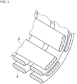
- As shown in
Fig. 3 , it is necessary for the reinforcing material to bend in various directions. In this way, at a location formed by bending the reinforcing material composed of a plurality of fiber layers, such as a bent portion of a structure, there will be situations where it is difficult to improve accuracy of identifying which fiber layer the fiber bundle contained in the fiber-reinforced material belongs to. The steeper the bending angle and the more the bending direction increases in a plurality of directions, the more difficult it is to identify the fiber layer to which the fiber bundle of interest belongs. -
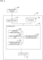
Fig. 4 is a block diagram showing a configuration of the identification device. - As shown in
Fig. 4 , theidentification device 20 includes areceiving unit 21, adatabase 23, acontroller 25, and anoutput unit 27. Thecontroller 25 is connected so as to be able to communicate with thereceiving unit 21, thedatabase 23, and theoutput unit 27. - In addition, the
output unit 27 may be provided by theidentification device 20 itself, or may be installed outside theidentification device 20 and connected to theidentification device 20 by a wireless or wired network. - The
receiving unit 21 is connected by a wireless or wired network so as to be able to communicate with themeasuring device 30. The receivingunit 21 receives data regarding a physical quantity distribution inside the fiber-reinforced material acquired by the measuringdevice 30. - The
database 23 stores information necessary for binarization performed by alabel generation unit 253, which will be described later. For example, when thelabel generation unit 253 performs binarization using a learning model, thedatabase 23 stores the learning model generated based on a teacher data paired with the physical quantity distribution and a distribution of the fiber layer inside the fiber-reinforced material obtained by directly molding the reinforcing material having a non-bent shape (initial shape). - For example, when focusing on a position inside the fiber-reinforced material, the learning model may be configured to output a label indicating which of the multiple fiber layers composing the reinforcing material the position belongs to, based on the distribution of the physical quantity at and around the position. As an example of the method of labeling each dot belonging to a certain area and performing binarization in this way, there is semantic segmentation.
- In addition, the
database 23 may store data regarding the physical quantity distribution inside the fiber-reinforced material acquired by the receivingunit 21. - The
output unit 27 outputs information generated by thecontroller 25 described later. In particular, theoutput unit 27 outputs a label mapped to the predetermined shape of the fiber-reinforced material by thecontroller 25 to the user or the like, wherein the label identifies any of the plurality of fiber layers constituting the fiber-reinforced material. - For example, the
output unit 27 may be a display that presents information to the user by displaying figures and characters by combining a plurality of display pixels, or a speaker that notifies the user of the information by voice. The method of outputting information by theoutput unit 27 is not limited to the examples given here. - The controller 25 (control unit) is a general-purpose computer including a CPU (central processing unit), a memory, and an input / output unit. A computer program (identification program) for functioning as the identification device is installed in the
controller 25. By executing the computer program, thecontroller 25 functions as a plurality of information processing circuits (251, 253, 255, 257) included in the identification device. The computer program (identification program) may be stored in a storage medium that can be read and written by a computer. - The present disclosure shows an example of realizing the plurality of information processing circuits (251, 253, 255, 257) by software. However, it is also possible to configure the information processing circuits (251, 253, 255, 257) by preparing dedicated hardware for executing each of the following information processing. Further, the plurality of information processing circuits (251, 253, 255, 257) may be configured by individual hardware. Further, the information processing circuit (251, 253, 255, 257) may also be used as a control unit used for monitoring or controlling the measuring
device 30. - As shown in
Fig. 4 , thecontroller 25 includes amapping execution unit 251, alabel generation unit 253, a reversemapping execution unit 255, and a deformationdata acquisition unit 257 as the plurality of information processing circuits (251, 253, 255, 257). - The deformation
data acquisition unit 257 acquires deformation data that associates the predetermined shape of the reinforcing material constituting the fiber-reinforced material with the initial shape of the reinforcing material. Here, the deformation data is, for example, data in which each node of the mesh structure representing the initial shape of the reinforcing material (pre-deformation node) is associated with each node of the mesh structure representing the predetermined shape of the reinforcing material (post-deformation node). - The deformation
data acquisition unit 257 may expand the predetermined shape into a flat initial shape based on an existing calculation method for calculating a plane development from a three-dimensional structure, and calculate the deformation data. Further, the deformationdata acquisition unit 257 may calculate the deformation data by deformation simulation using the finite element method or the like with reference to the step of deforming the reinforcing material from the initial shape to the predetermined shape when molding the fiber-reinforced material. In addition, the deformation data may be set by the user. - The deformation
data acquisition unit 257 may set an analysis target range among the fiber-reinforced material and may calculate the deformation data of the shape of the analysis target range by analyzing the shape of the analysis target range as the predetermined shape. Further, the deformationdata acquisition unit 257 may calculate the deformation data for the initial shape specified by the user. In addition, the user may set the deformation data itself. - The
mapping execution unit 251 maps the acquired physical quantity distribution to the initial shape based on the deformation data, and generates the first data. Specifically, when the physical quantity at the post-deformation node related to the predetermined shape can be obtained based on the physical quantity distribution, themapping execution unit 251 refers to the pre-deformation node corresponding to the post-deformation node based on the deformation data, and associates the physical quantity at the post-deformation node with the pre-deformation node referred to and obtained. In this way, themapping execution unit 251 generates the first data in which the value of the physical quantity is set based on the physical quantity distribution for each of the pre-deformation nodes related to the initial shape. - The
label generation unit 253 binarizes the first data and generates a second data in which the label identifying the fiber layer constituting the reinforcing material is mapped to the initial shape. For example, by using the learning model stored in thedatabase 23, thelabel generation unit 253 associates a label indicating the fiber layer at the position of the pre-deformation node related to the initial shape with the pre-deformation node. In this way, thelabel generation unit 253 generates the second data in which the label identifying the fiber layer is set for each of the pre-deformation nodes related to the initial shape. - The reverse
mapping execution unit 255 maps the label set by thelabel generation unit 253 to the predetermined shape by mapping the second data to the predetermined shape based on the deformation data. Specifically, when the label associated with the pre-deformation node related to the initial shape can be obtained in the second data, the reversemapping execution unit 255 refers to the post-deformation node corresponding to the pre-deformation node based on the deformation data, and associates the label of the pre-deformation node with the post-deformation node referred to and obtained. In this way, the reversemapping execution unit 255 generates data in which a label for identifying the fiber layer is set for each of the post-deformation nodes related to the predetermined shape. - The data generated by the reverse
mapping execution unit 255 is output to the outside via theoutput unit 27. - As described in detail above, regarding to a fiber-reinforced material formed by deforming a reinforcing material composed of a plurality of fiber layers from an initial shape and molding into a predetermined shape, an identification device, an identification method, and an identification program generate a first data in which a physical quantity distribution inside the fiber-reinforced material is mapped to the initial shape. The identification device, the identification method, and the identification program perform binarization of the first data to generate a second data in which a label identifying the fiber layer is mapped to the initial shape, and map the second data to a predetermined shape, based on a deformation data.
- As a result, it is possible to automate the identification of a fiber layer in a fiber-reinforced material and to reduce the time and cost required for inspecting the orientation of the reinforced fiber. Further, in a portion formed by bending the reinforcing material composed of a plurality of fiber layers such as a bent portion of a structure, the accuracy of identification when identifying which fiber layer the fiber bundle contained in the fiber-reinforced material belongs to, can be improved.
- The binarization may be based on a learning model generated based on teacher data paired with the physical quantity distribution inside the fiber-reinforced material molded in the initial shape and a distribution of the fiber layer. As a result, even at a predetermined shape where the bending direction of the reinforcing material is a complicated, the identification of the fiber layer can be carried out based on the teacher data paired with the physical quantity distribution inside the fiber-reinforced material formed in the initial shape and the distribution of the fiber layer. Therefore, it is not necessary to prepare teacher data corresponding to a complicated predetermined shape, and it is possible to automate the identification of the fiber layer in the fiber-reinforced material having various shapes. As a result, the accuracy of identification of the fiber layer can be improved.
- The binarization may be based on semantic segmentation. Thereby, the inside of the fiber-reinforced material whose physical quantity distribution is measured can be classified into a plurality of regions for each fiber layer. As a result, the fiber layer to which the fiber inside the fiber-reinforced material belongs can be easily identified based on the position information of the fiber.
- The deformation data may be generated based on a calculation method for expanding the reinforcing material from the predetermined shape to the initial shape. This eliminates the need for the user to separately instruct the correspondence between the predetermined shape and the initial shape during the analysis of the fiber-reinforced material. As a result, it is possible to automate the identification of fiber layers in fiber-reinforced materials having various shapes. As a result, the accuracy of identifying the fiber layer can be improved.
- Respective functions described in the present disclosure may be implemented by one or plural processing circuits. The processing circuits include programmed processors, electrical circuits, etc., and include devices such as an application specific integrated circuit (ASIC) and conventional circuit elements that are arranged to execute the functions described in the present disclosure.
- According to the present disclosure, it is possible to automate the identification of the fiber layer in the fiber-reinforced material and to reduce the time and cost required for inspecting the orientation of the reinforced fiber. Thus, for example, it is possible to contribute to Goal 12 of the United Nations-led Sustainable Development Goals (SDGs): "Ensure sustainable consumption and production patterns."
- It goes without saying that the present disclosure includes various embodiments not described here. Therefore, the technical scope of the present disclosure is defined only by the matters relating to the reasonable claims from the above description.
- This application claims priority based on
Japanese Patent Application No. 2020-218938 filed on December 28, 2020 -
- 1
- reinforced fiber
- 3, 5
- fiber bundle
- 20
- identification device
- 21
- receiving unit
- 23
- database
- 25
- controller
- 251
- mapping execution unit
- 253
- label generation unit
- 255
- reverse mapping execution unit
- 257
- deformation data acquisition unit
- 27
- output unit
- 30
- measuring device
Claims (6)
- An identification device for a fiber-reinforced material formed by deforming a reinforcing material composed of a plurality of fiber layers from an initial shape and molding into a predetermined shape, including:a receiver configured to receive a physical quantity distribution inside the fiber-reinforced material, anda controller configured to identify to which a fiber layer a fiber contained in the fiber-reinforced material belong, based on the physical quantity distribution, whereinthe controller is configuredto generate a first data in which the physical quantity distribution is mapped to the initial shape based on a deformation data that associates the initial shape with the predetermined shape,to perform binarization of the first data to generate a second data in which a label identifying the fiber layer is mapped to the initial shape, andto map the label to the predetermined shape by mapping the second data to the predetermined shape based on the deformation data.
- The identification device according to claim 1, wherein the binarization is based on a learning model generated based on teacher data paired with the physical quantity distribution inside the fiber-reinforced material molded in the initial shape and a distribution of the fiber layer.
- The identification device according to claim 1 or 2, wherein the binarization is based on semantic segmentation.
- The identification device according to any one of claims 1 to 3, wherein the deformation data is generated based on a calculation method for expanding the reinforcing material from the predetermined shape to the initial shape.
- An identification method for identifying to which a fiber layer a fiber contained in a fiber-reinforced material belong, based on a physical quantity distribution inside the fiber-reinforced material wherein the fiber-reinforced material is formed by deforming a reinforcing material composed of a plurality of fiber layers from an initial shape and molding into a predetermined shape, comprising:generating a first data in which the physical quantity distribution is mapped to the initial shape based on a deformation data that associates the initial shape with the predetermined shape,performing binarization of the first data to generate a second data in which a label identifying the fiber layer is mapped to the initial shape, andmapping the label to the predetermined shape by mapping the second data to the predetermined shape based on the deformation data.
- A non-transitory computer-readable storage medium storing a program for causing a computer to execute processing for identifying to which a fiber layer a fiber contained in a fiber-reinforced material belong, based on a physical quantity distribution inside the fiber-reinforced material wherein the fiber-reinforced material is formed by deforming a reinforcing material composed of a plurality of fiber layers from an initial shape and molding into a predetermined shape,
the processing comprising:generating a first data in which the physical quantity distribution is mapped to the initial shape based on a deformation data that associates the initial shape with the predetermined shape,performing binarization of the first data to generate a second data in which a label identifying the fiber layer is mapped to the initial shape, andmapping the label to the predetermined shape by mapping the second data to the predetermined shape based on the deformation data.
Applications Claiming Priority (2)
| Application Number | Priority Date | Filing Date | Title |
|---|---|---|---|
| JP2020218938 | 2020-12-28 | ||
| PCT/JP2021/032693 WO2022145091A1 (en) | 2020-12-28 | 2021-09-06 | Identification device, identification method, and identification program for identifying fiber layer in fiber-reinforced material |
Publications (2)
| Publication Number | Publication Date |
|---|---|
| EP4206663A1 true EP4206663A1 (en) | 2023-07-05 |
| EP4206663A4 EP4206663A4 (en) | 2024-09-18 |
Family
ID=82259185
Family Applications (1)
| Application Number | Title | Priority Date | Filing Date |
|---|---|---|---|
| EP21914952.3A Pending EP4206663A4 (en) | 2020-12-28 | 2021-09-06 | Identification device, identification method, and identification program for identifying fiber layer in fiber-reinforced material |
Country Status (4)
| Country | Link |
|---|---|
| US (1) | US12472706B2 (en) |
| EP (1) | EP4206663A4 (en) |
| JP (1) | JP7464150B2 (en) |
| WO (1) | WO2022145091A1 (en) |
Family Cites Families (16)
| Publication number | Priority date | Publication date | Assignee | Title |
|---|---|---|---|---|
| JP3237810B2 (en) * | 1994-03-18 | 2001-12-10 | 株式会社豊田中央研究所 | Stress detection method |
| FR2952577B1 (en) * | 2009-11-19 | 2011-11-04 | Airbus Operations Sas | METHOD FOR MANUFACTURING A CURVED PIECE OF COMPOSITE MATERIAL AND DEVICE FOR MANUFACTURING A CURVED PIECE OF COMPOSITE MATERIAL |
| KR20150023381A (en) * | 2012-06-14 | 2015-03-05 | 제온 코포레이션 | Crosslinkable resin molded body, crosslinked resin molded body, and laminate |
| JP6118698B2 (en) * | 2013-09-30 | 2017-04-19 | 株式会社Ihi | Image analysis apparatus and program |
| JP6333018B2 (en) * | 2014-03-28 | 2018-05-30 | キヤノン株式会社 | Nanofiber structure, collection device using the same, and manufacturing method of nanofiber structure |
| WO2016052489A1 (en) * | 2014-09-29 | 2016-04-07 | 株式会社Ihi | Image analysis device, image analysis method, and program |
| EP3375588B1 (en) * | 2015-08-04 | 2020-11-25 | Mitsubishi Chemical Corporation | Fiber-reinforced plastic and method for producing same |
| JP6680564B2 (en) * | 2016-02-29 | 2020-04-15 | 株式会社Ihi | Material shape simulation device, material shape simulation method, and three-dimensional woven fiber component manufacturing method |
| JP6681221B2 (en) * | 2016-03-03 | 2020-04-15 | 株式会社Ihi | Structure analysis device, structure analysis method, and three-dimensional woven fiber material manufacturing method |
| KR102245529B1 (en) * | 2016-03-30 | 2021-04-30 | 아사히 가세이 가부시키가이샤 | Resin composite film containing cellulose fine fiber layer |
| JP7067221B2 (en) | 2018-04-12 | 2022-05-16 | コニカミノルタ株式会社 | X-ray system |
| ES2964215T3 (en) * | 2018-06-29 | 2024-04-04 | Univ Antwerpen | Radiation Imaging Article Inspection Using an Iterative Projection Matching Approach |
| JP2020126023A (en) * | 2019-02-06 | 2020-08-20 | 三井化学株式会社 | Method and device for analyzing molding of reinforced resin composition |
| JP7176617B2 (en) * | 2019-03-27 | 2022-11-22 | 株式会社Ihi | Strength evaluation device and strength evaluation method |
| CN110276814B (en) * | 2019-06-05 | 2022-05-10 | 上海大学 | A fast reconstruction method for the mesostructure of braided composites based on topological features |
| CN111832570B (en) * | 2020-07-02 | 2024-08-16 | 北京工业大学 | Image semantic segmentation model training method and system |
-
2021
- 2021-09-06 EP EP21914952.3A patent/EP4206663A4/en active Pending
- 2021-09-06 JP JP2022572909A patent/JP7464150B2/en active Active
- 2021-09-06 WO PCT/JP2021/032693 patent/WO2022145091A1/en not_active Ceased
-
2023
- 2023-02-09 US US18/166,596 patent/US12472706B2/en active Active
Also Published As
| Publication number | Publication date |
|---|---|
| JP7464150B2 (en) | 2024-04-09 |
| JPWO2022145091A1 (en) | 2022-07-07 |
| US20230191727A1 (en) | 2023-06-22 |
| EP4206663A4 (en) | 2024-09-18 |
| WO2022145091A1 (en) | 2022-07-07 |
| US12472706B2 (en) | 2025-11-18 |
Similar Documents
| Publication | Publication Date | Title |
|---|---|---|
| CN110276814B (en) | A fast reconstruction method for the mesostructure of braided composites based on topological features | |
| US9046353B2 (en) | System and method for remote full field three-dimensional displacement and strain measurements | |
| JP6789452B1 (en) | Crack estimation device, crack estimation method, crack inspection method and failure diagnosis method | |
| JP5588713B2 (en) | Simulation apparatus and computer program therefor | |
| WO2021152811A1 (en) | Crack estimation device, fault diagnosis device, method for estimating crack, and method for diagnosing fault in dynamo-electric machine | |
| JP6681221B2 (en) | Structure analysis device, structure analysis method, and three-dimensional woven fiber material manufacturing method | |
| US20130336576A1 (en) | Metallographic method for accurate measurement of pore sizes and distributions in metal castings | |
| Zdziebko et al. | Synthetic image generation using the finite element method and blender graphics program for modeling of vision-based measurement systems | |
| JP4801783B2 (en) | Image processing system and image processing method | |
| Jung et al. | Cross-sectional constants of composite blades using computed tomography technique and finite element analysis | |
| US12472706B2 (en) | Identification device, identification method, and identification program for identifying fiber layer in fiber-reinforced material | |
| JP2015191387A (en) | Wire harness wiring route evaluation method, system thereof, and program thereof | |
| US20060235656A1 (en) | Product shape designing device | |
| Schmidt | Novel Methodologies for Digital Investigations of Clothing-Body-Interactions: Advancing Development of Tightly Fitted Clothing using 4D Scan Data and Finite Element Analysis Based on Deformable Human Body Models | |
| CN108026677A (en) | Predict the appearance of fabric surfaces | |
| JP2005525863A5 (en) | ||
| CN119006973A (en) | Fabric image processing device and method | |
| CN115165047A (en) | Electronic balance capable of synchronously measuring weight and gravity center | |
| US20250272958A1 (en) | Identification device, identification method, and identification program for identifying structural elements included in composite material | |
| EP1770566A1 (en) | Volume data cell labeling method and its program | |
| Guerra | Analysis of a 3d optical scanner based on photogrammetry suitable for industrial applications in close and micro-range | |
| EP4618003A1 (en) | Information processing method, information processing device, and information processing program for generating learning model capable of identifying void in composite material | |
| JP5849575B2 (en) | Data structure, computer program, and data acquisition apparatus | |
| JP2019191792A (en) | Object recognition apparatus, object recognition method and program | |
| Nunes et al. | iCorrVision-3D |
Legal Events
| Date | Code | Title | Description |
|---|---|---|---|
| STAA | Information on the status of an ep patent application or granted ep patent |
Free format text: STATUS: THE INTERNATIONAL PUBLICATION HAS BEEN MADE |
|
| PUAI | Public reference made under article 153(3) epc to a published international application that has entered the european phase |
Free format text: ORIGINAL CODE: 0009012 |
|
| STAA | Information on the status of an ep patent application or granted ep patent |
Free format text: STATUS: REQUEST FOR EXAMINATION WAS MADE |
|
| 17P | Request for examination filed |
Effective date: 20230328 |
|
| AK | Designated contracting states |
Kind code of ref document: A1 Designated state(s): AL AT BE BG CH CY CZ DE DK EE ES FI FR GB GR HR HU IE IS IT LI LT LU LV MC MK MT NL NO PL PT RO RS SE SI SK SM TR |
|
| DAV | Request for validation of the european patent (deleted) | ||
| DAX | Request for extension of the european patent (deleted) | ||
| A4 | Supplementary search report drawn up and despatched |
Effective date: 20240820 |
|
| RIC1 | Information provided on ipc code assigned before grant |
Ipc: G01N 21/84 20060101ALN20240813BHEP Ipc: B29C 70/54 20060101ALN20240813BHEP Ipc: B29C 70/50 20060101ALN20240813BHEP Ipc: B29C 70/22 20060101ALN20240813BHEP Ipc: G06T 11/00 20060101ALI20240813BHEP Ipc: G06T 7/00 20170101ALI20240813BHEP Ipc: G01N 33/00 20060101ALI20240813BHEP Ipc: G01N 23/046 20180101AFI20240813BHEP |