EP4206624A1 - Vibration distribution measuring device and method of same - Google Patents
Vibration distribution measuring device and method of same Download PDFInfo
- Publication number
- EP4206624A1 EP4206624A1 EP20951428.0A EP20951428A EP4206624A1 EP 4206624 A1 EP4206624 A1 EP 4206624A1 EP 20951428 A EP20951428 A EP 20951428A EP 4206624 A1 EP4206624 A1 EP 4206624A1
- Authority
- EP
- European Patent Office
- Prior art keywords
- window section
- vibration
- measured
- optical
- optical fiber
- Prior art date
- Legal status (The legal status is an assumption and is not a legal conclusion. Google has not performed a legal analysis and makes no representation as to the accuracy of the status listed.)
- Granted
Links
Images



Classifications
-
- G—PHYSICS
- G01—MEASURING; TESTING
- G01D—MEASURING NOT SPECIALLY ADAPTED FOR A SPECIFIC VARIABLE; ARRANGEMENTS FOR MEASURING TWO OR MORE VARIABLES NOT COVERED IN A SINGLE OTHER SUBCLASS; TARIFF METERING APPARATUS; MEASURING OR TESTING NOT OTHERWISE PROVIDED FOR
- G01D5/00—Mechanical means for transferring the output of a sensing member; Means for converting the output of a sensing member to another variable where the form or nature of the sensing member does not constrain the means for converting; Transducers not specially adapted for a specific variable
- G01D5/26—Mechanical means for transferring the output of a sensing member; Means for converting the output of a sensing member to another variable where the form or nature of the sensing member does not constrain the means for converting; Transducers not specially adapted for a specific variable characterised by optical transfer means, i.e. using infrared, visible, or ultraviolet light
- G01D5/32—Mechanical means for transferring the output of a sensing member; Means for converting the output of a sensing member to another variable where the form or nature of the sensing member does not constrain the means for converting; Transducers not specially adapted for a specific variable characterised by optical transfer means, i.e. using infrared, visible, or ultraviolet light with attenuation or whole or partial obturation of beams of light
- G01D5/34—Mechanical means for transferring the output of a sensing member; Means for converting the output of a sensing member to another variable where the form or nature of the sensing member does not constrain the means for converting; Transducers not specially adapted for a specific variable characterised by optical transfer means, i.e. using infrared, visible, or ultraviolet light with attenuation or whole or partial obturation of beams of light the beams of light being detected by photocells
- G01D5/353—Mechanical means for transferring the output of a sensing member; Means for converting the output of a sensing member to another variable where the form or nature of the sensing member does not constrain the means for converting; Transducers not specially adapted for a specific variable characterised by optical transfer means, i.e. using infrared, visible, or ultraviolet light with attenuation or whole or partial obturation of beams of light the beams of light being detected by photocells influencing the transmission properties of an optical fibre
- G01D5/35338—Mechanical means for transferring the output of a sensing member; Means for converting the output of a sensing member to another variable where the form or nature of the sensing member does not constrain the means for converting; Transducers not specially adapted for a specific variable characterised by optical transfer means, i.e. using infrared, visible, or ultraviolet light with attenuation or whole or partial obturation of beams of light the beams of light being detected by photocells influencing the transmission properties of an optical fibre using other arrangements than interferometer arrangements
- G01D5/35354—Sensor working in reflection
- G01D5/35358—Sensor working in reflection using backscattering to detect the measured quantity
- G01D5/35361—Sensor working in reflection using backscattering to detect the measured quantity using elastic backscattering to detect the measured quantity, e.g. using Rayleigh backscattering
-
- G—PHYSICS
- G01—MEASURING; TESTING
- G01H—MEASUREMENT OF MECHANICAL VIBRATIONS OR ULTRASONIC, SONIC OR INFRASONIC WAVES
- G01H9/00—Measuring mechanical vibrations or ultrasonic, sonic or infrasonic waves by using radiation-sensitive means, e.g. optical means
- G01H9/004—Measuring mechanical vibrations or ultrasonic, sonic or infrasonic waves by using radiation-sensitive means, e.g. optical means using fibre optic sensors
Definitions
- the present disclosure relates to a vibration distribution measuring apparatus and a method thereof.
- DAS distributed acoustic sensing
- an object of the present disclosure is to enable the vibration analysis using the spectral shift under appropriate conditions according to a measurement object.
- a vibration distribution measuring apparatus of the present disclosure which is a vibration distribution measuring apparatus of the present disclosure.
- the optical spectrum of the window section is calculated using the window section in which the vibration amplitude in the window section in the optical fiber to be measured is larger than a threshold value defined in the window section.
- a vibration distribution measuring method of the present disclosure includes
- the optical spectrum of the window section is calculated using the window section in which the vibration amplitude in the window section in the optical fiber to be measured is larger than a threshold value defined in the window section.
- the DAS determines whether the DAS is applicable in consideration of an amplitude of vibration of a measurement object, and to optimize measurement conditions according to the measurement object.
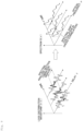
- Fig. 1 shows an example of the spectrum measured by a DAS.
- DAS Rayleigh backscattered light from a plurality of different times is measured. Specifically, a reference measurement, a first measurement, and a second measurement are sequentially performed. Then, the spectrum (distortion) of the Rayleigh backscattered light waveform at distances z 1 ⁇ z 2 at each point of time is analyzed to measure the time waveform of the vibration.
- Rayleigh backscattered light can be measured using, for example, optical frequency domain reflectometry (OFDR).
- OFDR optical frequency domain reflectometry
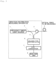
- Fig. 2 shows an example of a system configuration according to the present disclosure.
- the vibration distribution measuring apparatus of the present disclosure is connected to an optical fiber 4 to be measured.
- the vibration distribution measuring apparatus of the present disclosure has a configuration similar to that of OFDR.
- the vibration distribution measuring apparatus includes a frequency sweep light source 1, a coupler 2, a circulator 3, a coupler 5, a balance type photodetector 6, an A/D converter 7, and an analysis unit 8.
- the analysis unit 8 of the present disclosure can also be achieved by a computer and a program, and the program can be recorded in a recording medium or provided through a network.
- the coupler 2 divides light from the frequency sweep light source 1 into a reference optical path for local light and a measurement optical path for probe light.
- the probe light divided into the measurement optical path enters an optical fiber 4 to be measured via the coupler 2 and the circulator 3.
- the coupler 5 multiplexes probe light which is backscattered light in the optical fiber 4 to be measured and local light divided by the coupler 2.
- the balance type photodetector 6 receives the interference light multiplexed by the coupler 5.
- the A/D converter 7 converts the output signal of the balance type photodetector 6 into a digital signal.
- the analysis unit 8 analyzes using the digital signal from the A/D converter 7.
- the interference light incident on the balance type photodetector 6 has a beat frequency corresponding to the optical path length difference between the reference optical path and the measurement optical path.
- the backscattered light waveform in the optical fiber 4 to be measured is performed at least three times.
- the analysis unit 8 obtains an optical spectrum at a distance z 1 to z 2 in the optical fiber 4 to be measured using a time waveform of the interference light, and measures a vibration distribution in the optical fiber 4 to be measured on the basis of a temporal change of the optical spectrum.
- the vibration distribution in the optical fiber 4 to be measured is measured using the optical spectrum of a partial section defined by a window section in the optical fiber 4 to be measured.
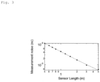
- Fig. 3 shows an example of a relationship between the analysis length w and the vibration amplitude of measurement object. • represents the measured value.
- ⁇ is a unit of strain representing an amount of expansion or contraction with respect to an original length. For example, when a length of 1 m expands or contracts 1 nm, it is expressed as distortion of 1n ⁇ .
- the frequency resolution ⁇ of the optical spectrum of Rayleigh scattered light is given by the formula of (3).
- the spectrum shift with respect to the distortion of the Rayleigh scattered light spectrum is given by the formula (2): Hg2, and the spectral shift amount ⁇ shift is proportional to the distortion amount. Accordingly, as shown in Fig. 3 , there is a trade-off relationship in which the longer the analysis length w, the higher the sensitivity for measuring a minute distortion (the smaller the noise of the measuring instrument), the lower the spatial resolution for analyzing the vibration.
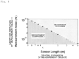
- the OFDR-DAS it is determined whether the OFDR-DAS is applicable from the vibration characteristics of the measurement object. More specifically, as shown in Fig. 4 , the optimum measurement conditions are set depending on the analysis length w, that is, the spatial expansion and vibration amplitude of the vibration of the measurement object. Specifically, the window section is set so that the vibration amplitude of the measurement object extracted in the window section is larger than a threshold value determined in the window section.
- the window section w is related to the above-mentioned condition (1) and condition (3). Since the window section satisfying the condition (1) having the maximum width has high sensitivity to vibration, the optimum window section is 1/2 the wavelength of vibration.
- the spatial resolution of the OFDR determines the minimum value of the window section from the Formula (1). Therefore, the spatial resolution of the OFDR determines the minimum wavelength that can be measured.
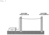
- FIG. 5 shows a measuring system.
- a pole #1 is disposed at a position of a distance of 15 m from the OFDR, and a pole #2 is disposed at a position of a distance of 45 m from the OFDR.
- the vibration distribution of the overhead cable between two poles #1 and #2 was measured.
- FIG. 6A shows a case where the spatial resolution ⁇ z is 0.8 m
- FIG. 6B shows a case where the spatial resolution ⁇ z is 1.6 m
- FIG. 6C shows a case where the spatial resolution ⁇ z is 9.5 m.
- the spatial resolution ⁇ z is 0.8 m
- the measurement sensitivity is low and the SNR is low, as shown in FIG. 6A
- the spatial resolution ⁇ z is 1.6 m
- both the spatial resolution and the sensitivity satisfy the measurement conditions as shown in FIG. 6B .
- the spatial resolution ⁇ z is 9.5 m
- the spatial resolution is large with respect to the spatial spread of the vibration to be measured, and the vibration distribution cannot be clearly measured.
- the analysis unit 8 of the present disclosure calculates the optical frequency response of the window section, using the window section determined depending on the vibration amplitude of the measurement object in the optical fiber 4 to be measured.
- the present disclosure allows for correct measurement of vibration in the DAS.
- Fig. 7 shows an example of the spectrum measured using OFDR.
- OFDR the optical frequency response of the entire fiber is measured. Therefore, the optical spectrum of a section having the loss distribution waveform can be analyzed. For example, a Fourier transform is performed on the optical frequency response r(v) of the entire optical fiber, and a loss distribution waveform r( ⁇ ) is obtained. Further, a window section is determined using the loss distribution waveform r( ⁇ ) and a spectrum S(v) of the window section is obtained by performing a Fourier transform of the window section.
- the optical fiber can be modeled as an FBG having a random refractive index distribution. Therefore, as shown in Fig. 8 , the spectrum analysis section can be designated, and the dynamic distortion (vibration) can be measured as the time change of the spectrum shift.
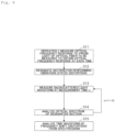
- Fig. 9 shows an example of the vibration distribution measuring method according to the present disclosure.
- the vibration distribution measuring method according to the present disclosure includes executing steps S11 to S15 in order.
- S12 A window section for analyzing the vibration (static distortion) is designated.
- S15 A time waveform of the frequency shift (distortion) is analyzed from the spectrogram.
- step S12 an optical frequency response r( ⁇ ) is Fourier-transformed to a loss distribution waveform r( ⁇ ). Then, a window section is set using the amplitude of the loss distribution waveform r( ⁇ ). Then, the optical spectrum of the set window section is extracted from the loss distribution waveform r( ⁇ ) obtained through the reference measurement, the first measurement and the second measurement, and the vibration distribution of the measurement object in the optical fiber 4 to be measured is measured using the plurality of extracted optical spectra.
- the window section is set to determine a spatial frequency and vibration sensitivity. If the vibration characteristics such as the wavelength and amplitude of the measurement object are known, the window section can be designated to satisfy the condition (1) and the condition (3) in the setting of the window section. When the vibration characteristics such as the wavelength and amplitude of the vibration to be measured are unknown, the window section is optimized according to the vibration characteristics by examining the window section, while changing the window section as shown in Fig. 6 in setting of the window section. Thus, according to the present disclosure, it can be determined whether the DAS can be applied in consideration of amplitude of vibration of the measurement object, and measurement conditions can be optimized depending on the measurement object.
- the present disclosure is applicable to the information and communication industry, equipment monitoring, crime prevention, and disaster monitoring.
Landscapes
- Physics & Mathematics (AREA)
- General Physics & Mathematics (AREA)
- Measurement Of Mechanical Vibrations Or Ultrasonic Waves (AREA)
Abstract
Description
- The present disclosure relates to a vibration distribution measuring apparatus and a method thereof.
- In a Rayleigh scattered light, a spectrum shifts in response to a vibration. A distributed acoustic sensing (DAS), which analyzes vibration using the spectral shift, has been proposed (for example, refer to NPL 1).
- In order to correctly measure the vibration, there are known a method using a sampling theorem in which a cycle of repeated measurement is made higher than a vibration frequency and a method using a spatial resolution in which a vibration analysis length is made shorter than a spatial expansion of vibration. However, the conditions for an amplitude of vibration are unclear.
-
- [NPL 1] Froggatt, Mark, and Jason Moore "High-spatial-resolution distributed strain measurement in optical fiber with Rayleigh scatter." Applied Optics 37.10 (1998): 1735-1740.
- [NPL 2] Koyamada, Yahei, et al. "Fiber-optic distributed strain and temperature sensing with very high measure and resolution over long range using coherent OTDR." Journal of Lightwave Technology 27.9 (2009): 1142-1146.
- In a vibration analysis using a spectral shift, in order to correctly measure vibration, it is necessary to appropriately set a condition for the amplitude of the vibration to be measured. Therefore, an object of the present disclosure is to enable the vibration analysis using the spectral shift under appropriate conditions according to a measurement object.
- A vibration distribution measuring apparatus of the present disclosure which
- measures backscattered light in an optical fiber to be measured a plurality of times at different times,
- extracts an optical spectrum of a determined window section from a plurality of backscattered light waveforms obtained by the measurement, and
- measures a vibration distribution in the optical fiber to be measured using optical spectra of the plurality of extracted
- backscattered light waveforms,
- In which the optical spectrum of the window section is calculated using the window section in which the vibration amplitude in the window section in the optical fiber to be measured is larger than a threshold value defined in the window section.
- A vibration distribution measuring method of the present disclosure includes
- measuring backscattered light in an optical fiber to be measured a plurality of times at different times,
- extracting an optical spectrum of a window section determined from a plurality of backscattered light waveforms obtained by the measurement, and
- measuring a vibration distribution in the optical fiber to be measured by a vibration distribution measuring apparatus using optical spectra of the plurality of extracted backscattered light waveforms,
- In which the optical spectrum of the window section is calculated using the window section in which the vibration amplitude in the window section in the optical fiber to be measured is larger than a threshold value defined in the window section.
- According to the present disclosure, it is possible to determine whether the DAS is applicable in consideration of an amplitude of vibration of a measurement object, and to optimize measurement conditions according to the measurement object.
-
- [
Fig. 1 ]
Fig. 1 shows an example of a spectrum measured in DAS. - [
Fig. 2 ]
Fig. 2 illustrates an example of the configuration of an OFDR. - [
Fig. 3 ]
Fig. 3 shows an example of a relationship between a vibration analysis length w and a vibration amplitude of the measurement object. - [
Fig. 4 ]
Fig. 4 shows an example of measurement conditions in the present disclosure; - [
Fig. 5 ]
Fig. 5 is a measurement system used in an example of vibration distribution measurement. - [
Fig. 6A ]
Fig. 6A is an example of measuring the vibration distribution when a spatial resolution is 0.8 m. - [
Fig. 6B ]
Fig. 6B is an example of measuring the vibration distribution when a spatial resolution is 1.6 m. - [
Fig. 6C ]
Fig. 6C is an example of measuring the vibration distribution when a spatial resolution is 9.5 m. - [
Fig. 7 ]
Fig. 7 shows an example of the spectrum measured using OFDR. - [
Fig. 8 ]
Fig. 8 shows an example of measurement of dynamic distortion (vibration) using a temporal change of the spectral shift. - [
Fig. 9 ]
Fig. 9 shows an example of the configuration of the vibration distribution measuring method according to the present disclosure. - Hereinafter, an embodiment of the present disclosure will be described in detail with reference to the drawings. The present disclosure is not limited to the embodiment described below. These implementation examples are only illustrative, and this disclosure can be carried out in a form with various changes and improvements based on the knowledge of those skilled in the art. Further, constituent elements with the same reference signs in the specification and the drawings are identical to each other.
-
Fig. 1 shows an example of the spectrum measured by a DAS. In the DAS, Rayleigh backscattered light from a plurality of different times is measured. Specifically, a reference measurement, a first measurement, and a second measurement are sequentially performed. Then, the spectrum (distortion) of the Rayleigh backscattered light waveform at distances z1~z2 at each point of time is analyzed to measure the time waveform of the vibration. Rayleigh backscattered light can be measured using, for example, optical frequency domain reflectometry (OFDR). -
Fig. 2 shows an example of a system configuration according to the present disclosure. The vibration distribution measuring apparatus of the present disclosure is connected to anoptical fiber 4 to be measured. The vibration distribution measuring apparatus of the present disclosure has a configuration similar to that of OFDR. Specifically, the vibration distribution measuring apparatus includes a frequency sweeplight source 1, acoupler 2, acirculator 3, acoupler 5, abalance type photodetector 6, an A/D converter 7, and ananalysis unit 8. Theanalysis unit 8 of the present disclosure can also be achieved by a computer and a program, and the program can be recorded in a recording medium or provided through a network. - The
coupler 2 divides light from the frequency sweeplight source 1 into a reference optical path for local light and a measurement optical path for probe light. The probe light divided into the measurement optical path enters anoptical fiber 4 to be measured via thecoupler 2 and thecirculator 3. Thecoupler 5 multiplexes probe light which is backscattered light in theoptical fiber 4 to be measured and local light divided by thecoupler 2. Thebalance type photodetector 6 receives the interference light multiplexed by thecoupler 5. The A/D converter 7 converts the output signal of thebalance type photodetector 6 into a digital signal. Theanalysis unit 8 analyzes using the digital signal from the A/D converter 7. - The interference light incident on the
balance type photodetector 6 has a beat frequency corresponding to the optical path length difference between the reference optical path and the measurement optical path. In the present disclosure, the backscattered light waveform in theoptical fiber 4 to be measured is performed at least three times. Theanalysis unit 8 obtains an optical spectrum at a distance z1 to z2 in theoptical fiber 4 to be measured using a time waveform of the interference light, and measures a vibration distribution in theoptical fiber 4 to be measured on the basis of a temporal change of the optical spectrum. Thus, in the present disclosure, the vibration distribution in theoptical fiber 4 to be measured is measured using the optical spectrum of a partial section defined by a window section in theoptical fiber 4 to be measured. - The vibration analysis length w (light spectrum analysis length) obtained by the extraction of the window section is expressed by the following formula.
[Math. 1]
- Here, parameters are as follows:
- N : Score of Rayleigh scattered light wave
- Δz : Spatial resolution of OFDR
- c : Light Speed of optical fiber
- F : Frequency sweep band of OFDR
- The spectral shift amount Δνshift due to distortion is represented by the following formula (NPL 2):
[Math. 2]
- Here, parameters are as follows:
- ε : Distortion of optical fiber
- v 0 : Center frequency of probe light
- The optical frequency resolution Δv of Rayleigh scattered light is expressed by the following formula.
[Math. 3]
-
Fig. 3 shows an example of a relationship between the analysis length w and the vibration amplitude of measurement object. • represents the measured value. ε is a unit of strain representing an amount of expansion or contraction with respect to an original length. For example, when a length of 1 m expands orcontracts 1 nm, it is expressed as distortion of 1nε. - The frequency resolution Δν of the optical spectrum of Rayleigh scattered light is given by the formula of (3). The higher the optical frequency resolution Δν is, the higher the sensitivity of the spectral shift amount Δνshift due to distortion is. According to the formula of (3), the longer the analysis length w is, the higher the optical frequency resolution Δv (sensitivity).
- On the other hand, the spectrum shift with respect to the distortion of the Rayleigh scattered light spectrum is given by the formula (2): Hg2, and the spectral shift amount Δνshift is proportional to the distortion amount. Accordingly, as shown in
Fig. 3 , there is a trade-off relationship in which the longer the analysis length w, the higher the sensitivity for measuring a minute distortion (the smaller the noise of the measuring instrument), the lower the spatial resolution for analyzing the vibration. -
- ▪The sensitivity to vibration amplitude and the vibration analysis length w are in a trade-off relationship.
- ▪The vibration analysis length w for correctly measuring the vibration needs to be smaller than the space expansion of the vibration which has been conventionally known, and needs to satisfy the condition of sensitivity to the vibration amplitude.
- Therefore, according to the present disclosure, it is determined whether the OFDR-DAS is applicable from the vibration characteristics of the measurement object. More specifically, as shown in
Fig. 4 , the optimum measurement conditions are set depending on the analysis length w, that is, the spatial expansion and vibration amplitude of the vibration of the measurement object. Specifically, the window section is set so that the vibration amplitude of the measurement object extracted in the window section is larger than a threshold value determined in the window section. - In order to measure the vibration, the following three conditions need to be satisfied.
- (1) The window section w has a spatial frequency which is twice the wave number of the vibration to be measured, that is, the spatial frequency, or more. That is, the window section w is 1/2 times or smaller than the wavelength of the vibration.
- (2) Measurement is performed at a repetition frequency of the probe light, which has a time frequency that is at least twice the frequency of the vibration to be measured, that is, the time frequency. That is, the measurement cycle is 1/2 times or smaller than the vibration cycle.
- (3) The vibration sensitivity is higher than the amplitude of the vibration to be measured.
- The window section w is related to the above-mentioned condition (1) and condition (3). Since the window section satisfying the condition (1) having the maximum width has high sensitivity to vibration, the optimum window section is 1/2 the wavelength of vibration. The spatial resolution of the OFDR determines the minimum value of the window section from the Formula (1). Therefore, the spatial resolution of the OFDR determines the minimum wavelength that can be measured.
- Referring to
Figs. 5 and6 , an example of measurement of the vibration distribution of the overhead cable is shown.Fig. 5 shows a measuring system. Apole # 1 is disposed at a position of a distance of 15 m from the OFDR, and apole # 2 is disposed at a position of a distance of 45 m from the OFDR. In this measurement system, the vibration distribution of the overhead cable between twopoles # 1 and #2 was measured. -
Fig. 6A shows a case where the spatial resolution Δz is 0.8 m,FIG. 6B shows a case where the spatial resolution Δz is 1.6 m, andFIG. 6C shows a case where the spatial resolution Δz is 9.5 m. When the spatial resolution Δz is 0.8 m, the measurement sensitivity is low and the SNR is low, as shown inFIG. 6A . When the spatial resolution Δz is 1.6 m, both the spatial resolution and the sensitivity satisfy the measurement conditions as shown inFIG. 6B . When the spatial resolution Δz is 9.5 m, as shown inFIG. 6C , the spatial resolution is large with respect to the spatial spread of the vibration to be measured, and the vibration distribution cannot be clearly measured. - As described above, the
analysis unit 8 of the present disclosure calculates the optical frequency response of the window section, using the window section determined depending on the vibration amplitude of the measurement object in theoptical fiber 4 to be measured. Thus, the present disclosure allows for correct measurement of vibration in the DAS. -
Fig. 7 shows an example of the spectrum measured using OFDR. In OFDR, the optical frequency response of the entire fiber is measured. Therefore, the optical spectrum of a section having the loss distribution waveform can be analyzed. For example, a Fourier transform is performed on the optical frequency response r(v) of the entire optical fiber, and a loss distribution waveform r(τ) is obtained. Further, a window section is determined using the loss distribution waveform r(τ) and a spectrum S(v) of the window section is obtained by performing a Fourier transform of the window section. - On the other hand, the optical fiber can be modeled as an FBG having a random refractive index distribution. Therefore, as shown in
Fig. 8 , the spectrum analysis section can be designated, and the dynamic distortion (vibration) can be measured as the time change of the spectrum shift. -
Fig. 9 shows an example of the vibration distribution measuring method according to the present disclosure. The vibration distribution measuring method according to the present disclosure includes executing steps S11 to S15 in order. - S11: An optical frequency response to the probe light of the optical fiber to be measured is repeatedly measured, and an optical frequency response r(v) of the entire optical fiber at each time is obtained.
- S12: A window section for analyzing the vibration (static distortion) is designated.
- S13: A backscattered light waveform at a measurement time n is measured.
- S14: An optical spectrum of the designated section is analyzed.
- S15: A time waveform of the frequency shift (distortion) is analyzed from the spectrogram.
- In the present disclosure, in step S12, an optical frequency response r(ν) is Fourier-transformed to a loss distribution waveform r(τ). Then, a window section is set using the amplitude of the loss distribution waveform r(τ). Then, the optical spectrum of the set window section is extracted from the loss distribution waveform r(τ) obtained through the reference measurement, the first measurement and the second measurement, and the vibration distribution of the measurement object in the
optical fiber 4 to be measured is measured using the plurality of extracted optical spectra. - The window section is set to determine a spatial frequency and vibration sensitivity. If the vibration characteristics such as the wavelength and amplitude of the measurement object are known, the window section can be designated to satisfy the condition (1) and the condition (3) in the setting of the window section. When the vibration characteristics such as the wavelength and amplitude of the vibration to be measured are unknown, the window section is optimized according to the vibration characteristics by examining the window section, while changing the window section as shown in
Fig. 6 in setting of the window section. Thus, according to the present disclosure, it can be determined whether the DAS can be applied in consideration of amplitude of vibration of the measurement object, and measurement conditions can be optimized depending on the measurement object. - The present disclosure is applicable to the information and communication industry, equipment monitoring, crime prevention, and disaster monitoring.
-
- 1
- Frequency sweep light source
- 2
- Coupler
- 3
- Circulator
- 4
- Optical fiber to be measured
- 5
- Coupler
- 6
- Balance type photodetector
- 7
- A/D converter
- 8
- Analysis unit
Claims (4)
- A vibration distribution measuring apparatus which measures backscattered light in an optical fiber to be measured a plurality of times at different times,extracts an optical spectrum of a window section determined from a plurality of backscattered light waveforms obtained by the measurement, andmeasures a vibration distribution in the optical fiber to be measured using optical spectra of the plurality of extracted backscattered light waveforms,wherein the optical spectrum of the window section is calculated using the window section in which the vibration amplitude in the window section in the optical fiber to be measured is larger than a threshold value defined in the window section.
- The vibration distribution measuring apparatus according to claim 1,wherein the backscattered light is an optical frequency response of a section extracted in a window section with respect to probe light,a loss distribution waveform of each backscattered light measured a plurality of times is generated using an optical frequency response of a section extracted in a window section with respect to the probe light, andan optical spectrum in the same window section is generated from each loss distribution waveformto extract an optical spectrum of a window section.
- The vibration distribution measuring apparatus according to claim 2,
wherein vibration in the optical fiber to be measured is measured using a spectral shift in the same window section. - A vibration distribution measuring method of a vibration distribution measuring apparatus comprising:measuring backscattered light in an optical fiber to be measured a plurality of times at different times,extracting an optical spectrum of a window section determined from a plurality of backscattered light waveforms obtained by the measurement, andmeasuring a vibration distribution in the optical fiber to be measured using optical spectra of the plurality of extracted backscattered light waveforms,wherein the optical spectrum of the window section is calculated using the window section in which the vibration amplitude in the window section in the optical fiber to be measured is larger than a threshold value defined in the window section.
Applications Claiming Priority (1)
| Application Number | Priority Date | Filing Date | Title |
|---|---|---|---|
| PCT/JP2020/032231 WO2022044174A1 (en) | 2020-08-26 | 2020-08-26 | Vibration distribution measuring device and method of same |
Publications (3)
| Publication Number | Publication Date |
|---|---|
| EP4206624A1 true EP4206624A1 (en) | 2023-07-05 |
| EP4206624A4 EP4206624A4 (en) | 2024-05-08 |
| EP4206624B1 EP4206624B1 (en) | 2025-02-26 |
Family
ID=80352841
Family Applications (1)
| Application Number | Title | Priority Date | Filing Date |
|---|---|---|---|
| EP20951428.0A Active EP4206624B1 (en) | 2020-08-26 | 2020-08-26 | Vibration distribution measuring device and method of same |
Country Status (5)
| Country | Link |
|---|---|
| US (1) | US12498257B2 (en) |
| EP (1) | EP4206624B1 (en) |
| JP (1) | JP7464133B2 (en) |
| CN (1) | CN116194740B (en) |
| WO (1) | WO2022044174A1 (en) |
Families Citing this family (2)
| Publication number | Priority date | Publication date | Assignee | Title |
|---|---|---|---|---|
| US20260029256A1 (en) * | 2022-08-01 | 2026-01-29 | Nippon Telegraph And Telephone Corporation | Optical path testing device and optical path testing method |
| US20260043685A1 (en) * | 2022-08-01 | 2026-02-12 | Ntt, Inc. | Optical path testing device and optical path testing method |
Family Cites Families (11)
| Publication number | Priority date | Publication date | Assignee | Title |
|---|---|---|---|---|
| JPS59197829A (en) * | 1983-04-26 | 1984-11-09 | Mitsubishi Electric Corp | Optical fiber vibration sensor |
| JPH0587684A (en) * | 1991-09-30 | 1993-04-06 | Nippon Telegr & Teleph Corp <Ntt> | Zero dispersion wavelength measuring device |
| JP2001215149A (en) * | 2000-02-02 | 2001-08-10 | Ono Sokki Co Ltd | Amplitude measuring device and amplitude measuring method |
| GB2489749B (en) * | 2011-04-08 | 2016-01-20 | Optasense Holdings Ltd | Fibre optic distributed sensing |
| GB201212701D0 (en) * | 2012-07-17 | 2012-08-29 | Silixa Ltd | Structure monitoring |
| US9823098B2 (en) * | 2014-05-05 | 2017-11-21 | Filippo Bastianini | Apparatus for interrogating distributed optical fibre sensors using a stimulated brillouin scattering optical frequency-domain interferometer |
| JP6277147B2 (en) * | 2015-03-04 | 2018-02-07 | 日本電信電話株式会社 | Optical fiber vibration measurement method and system |
| JP6494459B2 (en) * | 2015-07-24 | 2019-04-03 | 日本電信電話株式会社 | Vibration distribution measuring method and vibration distribution measuring apparatus |
| JP2019078632A (en) * | 2017-10-24 | 2019-05-23 | 長野計器株式会社 | Optical fiber sensor measuring device |
| CN108896274B (en) * | 2018-06-14 | 2019-12-27 | 大连理工大学 | Distributed optical fiber strain demodulation method based on subset window length optimization algorithm |
| JP6773091B2 (en) | 2018-09-07 | 2020-10-21 | 横河電機株式会社 | Optical fiber characteristic measuring device and optical fiber characteristic measuring method |
-
2020
- 2020-08-26 CN CN202080104705.1A patent/CN116194740B/en active Active
- 2020-08-26 US US18/020,969 patent/US12498257B2/en active Active
- 2020-08-26 WO PCT/JP2020/032231 patent/WO2022044174A1/en not_active Ceased
- 2020-08-26 JP JP2022544976A patent/JP7464133B2/en active Active
- 2020-08-26 EP EP20951428.0A patent/EP4206624B1/en active Active
Also Published As
| Publication number | Publication date |
|---|---|
| CN116194740A (en) | 2023-05-30 |
| EP4206624B1 (en) | 2025-02-26 |
| EP4206624A4 (en) | 2024-05-08 |
| WO2022044174A1 (en) | 2022-03-03 |
| US12498257B2 (en) | 2025-12-16 |
| JP7464133B2 (en) | 2024-04-09 |
| CN116194740B (en) | 2025-07-25 |
| US20230288231A1 (en) | 2023-09-14 |
| JPWO2022044174A1 (en) | 2022-03-03 |
Similar Documents
| Publication | Publication Date | Title |
|---|---|---|
| US10151626B2 (en) | Fibre optic distributed sensing | |
| US10247584B2 (en) | Fibre optic distributed sensing | |
| CN102292621B (en) | Improvements in Distributed Fiber Optic Sensing | |
| JP2018146371A (en) | Temperature-strain sensing device and temperature-strain sensing method | |
| Niklès | Fibre optic distributed scattering sensing system: Perspectives and challenges for high performance applications | |
| CN114543973A (en) | Distributed ultrahigh frequency vibration signal measuring method and optical fiber sensor | |
| CN106093962B (en) | A kind of interference velocity-measuring system and method | |
| CN114245862B (en) | Vibration distribution measuring device and method | |
| JP2019052938A (en) | Light reflection measuring apparatus and method | |
| JP2017026503A (en) | Vibration distribution measuring method and vibration distribution measuring apparatus | |
| CN116086589B (en) | A Data Analysis Method for Distributed Fiber Optic Vibration Sensing Systems | |
| US12498257B2 (en) | Distributed acoustic sensing device and method | |
| CN115824378B (en) | Vibration detection method of high-frequency response distributed optical fiber acoustic wave sensor | |
| CN113091947B (en) | ASE time domain related compression distributed optical fiber Raman temperature sensing device and method | |
| US11879803B2 (en) | Optical fiber evaluation method and optical fiber evaluation apparatus | |
| JP6706192B2 (en) | Propagation delay time difference measuring method between spatial channels and propagation delay time difference measuring apparatus between spatial channels | |
| CN119354245A (en) | Power cable monitoring system and method based on single-core optical fiber multi-parameter sensing | |
| Magalhães et al. | Curvature sensor based on a long-period grating in a fiber ring resonator interrogated by an OTDR | |
| WO2024069867A1 (en) | Device and method for analyzing optical fiber strain or temperature | |
| JP7459966B2 (en) | Frequency modulation amount measuring device and method | |
| EP4317920B1 (en) | Analysis device, measurement system, measurement method, and program | |
| JP7806810B2 (en) | Light measurement system and light measurement method | |
| Chang et al. | Multi-Resolution Integration Method for High Resolution Non-Uniform Distributed Strain Measurement in OFDR System | |
| Hernández-Martín et al. | Large CP-ϕOTDR Assisted by Raman Amplification for Long-Range Millikelvin Fiber Thermometry | |
| Zhong et al. | Vehicle-induced bridge dynamic response monitoring and displacement estimation using distributed acoustic sensing |
Legal Events
| Date | Code | Title | Description |
|---|---|---|---|
| STAA | Information on the status of an ep patent application or granted ep patent |
Free format text: STATUS: THE INTERNATIONAL PUBLICATION HAS BEEN MADE |
|
| PUAI | Public reference made under article 153(3) epc to a published international application that has entered the european phase |
Free format text: ORIGINAL CODE: 0009012 |
|
| STAA | Information on the status of an ep patent application or granted ep patent |
Free format text: STATUS: REQUEST FOR EXAMINATION WAS MADE |
|
| 17P | Request for examination filed |
Effective date: 20230124 |
|
| AK | Designated contracting states |
Kind code of ref document: A1 Designated state(s): AL AT BE BG CH CY CZ DE DK EE ES FI FR GB GR HR HU IE IS IT LI LT LU LV MC MK MT NL NO PL PT RO RS SE SI SK SM TR |
|
| DAV | Request for validation of the european patent (deleted) | ||
| DAX | Request for extension of the european patent (deleted) | ||
| A4 | Supplementary search report drawn up and despatched |
Effective date: 20240408 |
|
| RIC1 | Information provided on ipc code assigned before grant |
Ipc: H04B 10/071 20130101ALI20240402BHEP Ipc: G01D 5/353 20060101ALI20240402BHEP Ipc: G01H 9/00 20060101AFI20240402BHEP |
|
| GRAP | Despatch of communication of intention to grant a patent |
Free format text: ORIGINAL CODE: EPIDOSNIGR1 |
|
| STAA | Information on the status of an ep patent application or granted ep patent |
Free format text: STATUS: GRANT OF PATENT IS INTENDED |
|
| INTG | Intention to grant announced |
Effective date: 20241024 |
|
| GRAS | Grant fee paid |
Free format text: ORIGINAL CODE: EPIDOSNIGR3 |
|
| GRAA | (expected) grant |
Free format text: ORIGINAL CODE: 0009210 |
|
| STAA | Information on the status of an ep patent application or granted ep patent |
Free format text: STATUS: THE PATENT HAS BEEN GRANTED |
|
| AK | Designated contracting states |
Kind code of ref document: B1 Designated state(s): AL AT BE BG CH CY CZ DE DK EE ES FI FR GB GR HR HU IE IS IT LI LT LU LV MC MK MT NL NO PL PT RO RS SE SI SK SM TR |
|
| REG | Reference to a national code |
Ref country code: GB Ref legal event code: FG4D |
|
| REG | Reference to a national code |
Ref country code: CH Ref legal event code: EP |
|
| REG | Reference to a national code |
Ref country code: DE Ref legal event code: R096 Ref document number: 602020047043 Country of ref document: DE |
|
| REG | Reference to a national code |
Ref country code: IE Ref legal event code: FG4D |
|
| REG | Reference to a national code |
Ref country code: NL Ref legal event code: MP Effective date: 20250226 |
|
| PG25 | Lapsed in a contracting state [announced via postgrant information from national office to epo] |
Ref country code: RS Free format text: LAPSE BECAUSE OF FAILURE TO SUBMIT A TRANSLATION OF THE DESCRIPTION OR TO PAY THE FEE WITHIN THE PRESCRIBED TIME-LIMIT Effective date: 20250526 |
|
| PG25 | Lapsed in a contracting state [announced via postgrant information from national office to epo] |
Ref country code: FI Free format text: LAPSE BECAUSE OF FAILURE TO SUBMIT A TRANSLATION OF THE DESCRIPTION OR TO PAY THE FEE WITHIN THE PRESCRIBED TIME-LIMIT Effective date: 20250226 |
|
| PG25 | Lapsed in a contracting state [announced via postgrant information from national office to epo] |
Ref country code: PL Free format text: LAPSE BECAUSE OF FAILURE TO SUBMIT A TRANSLATION OF THE DESCRIPTION OR TO PAY THE FEE WITHIN THE PRESCRIBED TIME-LIMIT Effective date: 20250226 |
|
| PG25 | Lapsed in a contracting state [announced via postgrant information from national office to epo] |
Ref country code: ES Free format text: LAPSE BECAUSE OF FAILURE TO SUBMIT A TRANSLATION OF THE DESCRIPTION OR TO PAY THE FEE WITHIN THE PRESCRIBED TIME-LIMIT Effective date: 20250226 |
|
| REG | Reference to a national code |
Ref country code: LT Ref legal event code: MG9D |
|
| PG25 | Lapsed in a contracting state [announced via postgrant information from national office to epo] |
Ref country code: IS Free format text: LAPSE BECAUSE OF FAILURE TO SUBMIT A TRANSLATION OF THE DESCRIPTION OR TO PAY THE FEE WITHIN THE PRESCRIBED TIME-LIMIT Effective date: 20250626 Ref country code: NO Free format text: LAPSE BECAUSE OF FAILURE TO SUBMIT A TRANSLATION OF THE DESCRIPTION OR TO PAY THE FEE WITHIN THE PRESCRIBED TIME-LIMIT Effective date: 20250526 |
|
| PG25 | Lapsed in a contracting state [announced via postgrant information from national office to epo] |
Ref country code: NL Free format text: LAPSE BECAUSE OF FAILURE TO SUBMIT A TRANSLATION OF THE DESCRIPTION OR TO PAY THE FEE WITHIN THE PRESCRIBED TIME-LIMIT Effective date: 20250226 |
|
| PG25 | Lapsed in a contracting state [announced via postgrant information from national office to epo] |
Ref country code: HR Free format text: LAPSE BECAUSE OF FAILURE TO SUBMIT A TRANSLATION OF THE DESCRIPTION OR TO PAY THE FEE WITHIN THE PRESCRIBED TIME-LIMIT Effective date: 20250226 |
|
| PG25 | Lapsed in a contracting state [announced via postgrant information from national office to epo] |
Ref country code: LV Free format text: LAPSE BECAUSE OF FAILURE TO SUBMIT A TRANSLATION OF THE DESCRIPTION OR TO PAY THE FEE WITHIN THE PRESCRIBED TIME-LIMIT Effective date: 20250226 Ref country code: PT Free format text: LAPSE BECAUSE OF FAILURE TO SUBMIT A TRANSLATION OF THE DESCRIPTION OR TO PAY THE FEE WITHIN THE PRESCRIBED TIME-LIMIT Effective date: 20250626 |
|
| PG25 | Lapsed in a contracting state [announced via postgrant information from national office to epo] |
Ref country code: GR Free format text: LAPSE BECAUSE OF FAILURE TO SUBMIT A TRANSLATION OF THE DESCRIPTION OR TO PAY THE FEE WITHIN THE PRESCRIBED TIME-LIMIT Effective date: 20250527 Ref country code: BG Free format text: LAPSE BECAUSE OF FAILURE TO SUBMIT A TRANSLATION OF THE DESCRIPTION OR TO PAY THE FEE WITHIN THE PRESCRIBED TIME-LIMIT Effective date: 20250226 |
|
| REG | Reference to a national code |
Ref country code: AT Ref legal event code: MK05 Ref document number: 1771037 Country of ref document: AT Kind code of ref document: T Effective date: 20250226 |
|
| PG25 | Lapsed in a contracting state [announced via postgrant information from national office to epo] |
Ref country code: SE Free format text: LAPSE BECAUSE OF FAILURE TO SUBMIT A TRANSLATION OF THE DESCRIPTION OR TO PAY THE FEE WITHIN THE PRESCRIBED TIME-LIMIT Effective date: 20250226 |
|
| RAP4 | Party data changed (patent owner data changed or rights of a patent transferred) |
Owner name: NTT, INC. |
|
| PG25 | Lapsed in a contracting state [announced via postgrant information from national office to epo] |
Ref country code: SM Free format text: LAPSE BECAUSE OF FAILURE TO SUBMIT A TRANSLATION OF THE DESCRIPTION OR TO PAY THE FEE WITHIN THE PRESCRIBED TIME-LIMIT Effective date: 20250226 |
|
| PG25 | Lapsed in a contracting state [announced via postgrant information from national office to epo] |
Ref country code: DK Free format text: LAPSE BECAUSE OF FAILURE TO SUBMIT A TRANSLATION OF THE DESCRIPTION OR TO PAY THE FEE WITHIN THE PRESCRIBED TIME-LIMIT Effective date: 20250226 |
|
| PG25 | Lapsed in a contracting state [announced via postgrant information from national office to epo] |
Ref country code: IT Free format text: LAPSE BECAUSE OF FAILURE TO SUBMIT A TRANSLATION OF THE DESCRIPTION OR TO PAY THE FEE WITHIN THE PRESCRIBED TIME-LIMIT Effective date: 20250226 |
|
| PGFP | Annual fee paid to national office [announced via postgrant information from national office to epo] |
Ref country code: GB Payment date: 20250822 Year of fee payment: 6 |
|
| PG25 | Lapsed in a contracting state [announced via postgrant information from national office to epo] |
Ref country code: AT Free format text: LAPSE BECAUSE OF FAILURE TO SUBMIT A TRANSLATION OF THE DESCRIPTION OR TO PAY THE FEE WITHIN THE PRESCRIBED TIME-LIMIT Effective date: 20250226 |
|
| PG25 | Lapsed in a contracting state [announced via postgrant information from national office to epo] |
Ref country code: EE Free format text: LAPSE BECAUSE OF FAILURE TO SUBMIT A TRANSLATION OF THE DESCRIPTION OR TO PAY THE FEE WITHIN THE PRESCRIBED TIME-LIMIT Effective date: 20250226 Ref country code: CZ Free format text: LAPSE BECAUSE OF FAILURE TO SUBMIT A TRANSLATION OF THE DESCRIPTION OR TO PAY THE FEE WITHIN THE PRESCRIBED TIME-LIMIT Effective date: 20250226 |
|
| PG25 | Lapsed in a contracting state [announced via postgrant information from national office to epo] |
Ref country code: RO Free format text: LAPSE BECAUSE OF FAILURE TO SUBMIT A TRANSLATION OF THE DESCRIPTION OR TO PAY THE FEE WITHIN THE PRESCRIBED TIME-LIMIT Effective date: 20250226 |
|
| PG25 | Lapsed in a contracting state [announced via postgrant information from national office to epo] |
Ref country code: SK Free format text: LAPSE BECAUSE OF FAILURE TO SUBMIT A TRANSLATION OF THE DESCRIPTION OR TO PAY THE FEE WITHIN THE PRESCRIBED TIME-LIMIT Effective date: 20250226 |
|
| REG | Reference to a national code |
Ref country code: DE Ref legal event code: R097 Ref document number: 602020047043 Country of ref document: DE |
|
| PLBE | No opposition filed within time limit |
Free format text: ORIGINAL CODE: 0009261 |
|
| STAA | Information on the status of an ep patent application or granted ep patent |
Free format text: STATUS: NO OPPOSITION FILED WITHIN TIME LIMIT |
|
| REG | Reference to a national code |
Ref country code: CH Ref legal event code: L10 Free format text: ST27 STATUS EVENT CODE: U-0-0-L10-L00 (AS PROVIDED BY THE NATIONAL OFFICE) Effective date: 20260107 |
|
| 26N | No opposition filed |
Effective date: 20251127 |
|
| REG | Reference to a national code |
Ref country code: DE Ref legal event code: R119 Ref document number: 602020047043 Country of ref document: DE |
|
| REG | Reference to a national code |
Ref country code: CH Ref legal event code: H13 Free format text: ST27 STATUS EVENT CODE: U-0-0-H10-H13 (AS PROVIDED BY THE NATIONAL OFFICE) Effective date: 20260324 |
|
| PG25 | Lapsed in a contracting state [announced via postgrant information from national office to epo] |
Ref country code: MC Free format text: LAPSE BECAUSE OF FAILURE TO SUBMIT A TRANSLATION OF THE DESCRIPTION OR TO PAY THE FEE WITHIN THE PRESCRIBED TIME-LIMIT Effective date: 20250226 |
|
| PG25 | Lapsed in a contracting state [announced via postgrant information from national office to epo] |
Ref country code: LU Free format text: LAPSE BECAUSE OF NON-PAYMENT OF DUE FEES Effective date: 20250826 |
|
| PG25 | Lapsed in a contracting state [announced via postgrant information from national office to epo] |
Ref country code: CH Free format text: LAPSE BECAUSE OF NON-PAYMENT OF DUE FEES Effective date: 20250831 |