EP4206596A1 - Refrigeration appliance - Google Patents
Refrigeration appliance Download PDFInfo
- Publication number
- EP4206596A1 EP4206596A1 EP21879448.5A EP21879448A EP4206596A1 EP 4206596 A1 EP4206596 A1 EP 4206596A1 EP 21879448 A EP21879448 A EP 21879448A EP 4206596 A1 EP4206596 A1 EP 4206596A1
- Authority
- EP
- European Patent Office
- Prior art keywords
- electric box
- refrigerating appliance
- insertion portion
- protruding insertion
- cabinet
- Prior art date
- Legal status (The legal status is an assumption and is not a legal conclusion. Google has not performed a legal analysis and makes no representation as to the accuracy of the status listed.)
- Pending
Links
Images



Classifications
-
- F—MECHANICAL ENGINEERING; LIGHTING; HEATING; WEAPONS; BLASTING
- F25—REFRIGERATION OR COOLING; COMBINED HEATING AND REFRIGERATION SYSTEMS; HEAT PUMP SYSTEMS; MANUFACTURE OR STORAGE OF ICE; LIQUEFACTION SOLIDIFICATION OF GASES
- F25D—REFRIGERATORS; COLD ROOMS; ICE-BOXES; COOLING OR FREEZING APPARATUS NOT OTHERWISE PROVIDED FOR
- F25D29/00—Arrangement or mounting of control or safety devices
- F25D29/005—Mounting of control devices
-
- F—MECHANICAL ENGINEERING; LIGHTING; HEATING; WEAPONS; BLASTING
- F25—REFRIGERATION OR COOLING; COMBINED HEATING AND REFRIGERATION SYSTEMS; HEAT PUMP SYSTEMS; MANUFACTURE OR STORAGE OF ICE; LIQUEFACTION SOLIDIFICATION OF GASES
- F25D—REFRIGERATORS; COLD ROOMS; ICE-BOXES; COOLING OR FREEZING APPARATUS NOT OTHERWISE PROVIDED FOR
- F25D23/00—General constructional features
- F25D23/006—General constructional features for mounting refrigerating machinery components
Definitions
- the present invention relates to a refrigerating appliance, and in particular, to a refrigerating appliance with an electric box disposed in a machinery chamber.
- a storage chamber such as a refrigerating chamber, or the like, is formed inside a heat insulation cabinet, and the storage chamber is cooled by a refrigerating cycle to provide a suitable temperature range for cooling and preserving a stored object.
- the refrigerating cycle includes a compressor, a condenser, an expansion unit, and an evaporator.
- FIG. 8(A) is an upper sectional view of a position where the electric box 105 is connected
- FIG. 8(B) is an upper sectional view showing a state where the electric box 105 is displaced.
- FIGS. 8(A) and 8(B) show an outer-cabinet rear surface 104 using dotted lines.
- the refrigerant pipe is configured in the machinery chamber near the electric box, and the protruding insertion portion is configured at the end portion of the side of the electric box apart from the refrigerant pipe. Therefore, in the refrigerating appliance according to the present invention, even when the electric box is pressed by the refrigerant pipe, the movement of the electric box can be suppressed by inserting the protruding insertion portion into the opening portion at a position apart from the refrigerant pipe.
- a refrigerating appliance 10 according to an embodiment of the present invention will be described in detail based on the accompanying drawings. Further, in describing the present embodiment, the same reference numerals are used for the same members in principle, and redundant descriptions are omitted. In the present embodiment, the description is given using an up-down direction, a front-rear direction and a left-right direction, and the left-right direction refers to the left-right direction when the refrigerating appliance 10 is viewed from the rear.
- a defrosting heater 117 is configured inside the cooling chamber 115, and the defrosting heater 117 is located below the evaporator 116.
- the defrosting heater 117 is configured as a heater which generates heat by energization, and generates heat when energized during a defrosting stroke, and frost of the evaporator 116 is molten by the generated heat.
- Defrosted water generated by the defrosting reaches an evaporating dish 27 described later with reference to FIG. 3 , and is evaporated by heat exchange with a high-temperature compressed refrigerant or a compressor 22.
- a left end portion of the electric box 17 is fixed to a side surface of the outer-cabinet side surface 23, which forms a left side surface of the machinery chamber 14, by a connecting portion 29. Furthermore, the protruding insertion portion 25 is inserted into the opening portion 26, and the protruding insertion portion 25 is formed at a right end portion of the electric box 17. In this way, both end portions of the electric box 17 in a width direction are fixed to the heat insulation cabinet 11, thereby suppressing movement of the electric box 17 inside the machinery chamber 14.
- the movement of the electric box 17 can be suppressed by inserting the protruding insertion portion 25 into the opening portion 26 at a position apart from the refrigerant pipe 28.
Landscapes
- Engineering & Computer Science (AREA)
- Chemical & Material Sciences (AREA)
- Combustion & Propulsion (AREA)
- Physics & Mathematics (AREA)
- Mechanical Engineering (AREA)
- Thermal Sciences (AREA)
- General Engineering & Computer Science (AREA)
- Refrigerator Housings (AREA)
- Devices That Are Associated With Refrigeration Equipment (AREA)
Abstract
Description
- The present invention relates to a refrigerating appliance, and in particular, to a refrigerating appliance with an electric box disposed in a machinery chamber.
- In a general refrigerating appliance, a storage chamber, such as a refrigerating chamber, or the like, is formed inside a heat insulation cabinet, and the storage chamber is cooled by a refrigerating cycle to provide a suitable temperature range for cooling and preserving a stored object. The refrigerating cycle includes a compressor, a condenser, an expansion unit, and an evaporator.
- The following patent document 1 (
Japanese publication No. 2015-1344 -
FIG. 7 is a view showing the refrigeratingappliance 100 according to the background,FIG. 7(A) is a perspective view of themachinery chamber 102 as viewed from the upper rear side, andFIG. 7(B) is a perspective view of a position where theelectric box 105 is connected as viewed from the lower rear side. - Referring to
FIG. 7(A) , themachinery chamber 102 is defined and formed at a rear lower end of theheat insulation cabinet 101 of the refrigeratingappliance 100. Themachinery chamber 102 receives structural apparatuses of the refrigerating cycle, and here, only thecompressor 103 and theelectric box 105 are illustrated. Theelectric box 105 includes, for example, a control substrate having a control circuit for controlling the refrigerating cycle. - Referring to
FIG. 7(B) , a left end of theelectric box 105 is fixed to a rear side of an outer-cabinet side surface 107 by ascrew 106. With this structure, a position of theelectric box 105 inside themachinery chamber 102 is defined. - However, in the above refrigerating appliance, there still exists room for an improvement in the structure for fixing the
electric box 105. - With reference to
FIG. 8 , a problem of the refrigeratingappliance 100 according to the background will be described.FIG. 8(A) is an upper sectional view of a position where theelectric box 105 is connected, andFIG. 8(B) is an upper sectional view showing a state where theelectric box 105 is displaced. Further,FIGS. 8(A) and 8(B) show an outer-cabinetrear surface 104 using dotted lines. - Referring to
FIG. 8(A) , the left end of theelectric box 105 is fixed to the rear side of the outer-cabinet side surface 107 by thescrew 106. Furthermore, arefrigerant pipe 108 is configured between theelectric box 105 and the outer-cabinet side surface 107. - Here, in a manufacturing process of the refrigerating
appliance 10, there exist operations of drawing one end of therefrigerant pipe 108 out of themachinery chamber 102, welding therefrigerant pipe 108, and then returning therefrigerant pipe 108 to themachinery chamber 102. At this point, when therefrigerant pipe 108 is not returned to a prescribed position, therefrigerant pipe 108 may press theelectric box 105. - Referring to
FIG. 8(B) , therefrigerant pipe 108 is not returned to the prescribed position, and thus, when therefrigerant pipe 108 rightwards presses theelectric box 105, theelectric box 105 is displaced as follows: theelectric box 105 rotates with the position of fixation by thescrew 106 as a center. Thus, a part of theelectric box 105 protrudes rearwards from the outer-cabinetrear surface 104. When theelectric box 105 protrudes from the outer-cabinetrear surface 104, in a use condition of the refrigeratingappliance 100, there exists a concern that water flows along an outer surface of the outer-cabinetrear surface 104 and may wet theelectric box 105, causing a short circuit in an electrical circuit received in theelectric box 105. - Furthermore, when the
electric box 105 is pulled by a power line, a wire harness, or the like (not shown), as shown inFIG. 8(B) , theelectric box 105 may be inadvertently displaced into the outer-cabinetrear surface 104. - The present invention is made in view of the above conditions, and an object thereof is to provide a refrigerating appliance capable of suppressing displacement of an electric box in a machinery chamber with a simple structure.
- The refrigerating appliance according to the present invention includes: a machinery chamber defined and formed in a heat insulation cabinet; and an electric box received in the machinery chamber, one end of the electric box being connected to a side surface of the machinery chamber by a connecting portion, a protruding insertion portion being inserted into an opening portion, the protruding insertion portion being provided by forming a part of the electric box into a protruding shape, and the opening portion being formed in an inner surface of the machinery chamber.
- Furthermore, in the refrigerating appliance according to the present invention, the connecting portion is configured on one end side of the electric box, and the protruding insertion portion is configured on an end side of the electric box opposite to the connecting portion.
- Furthermore, in the refrigerating appliance according to the present invention, a refrigerant pipe is configured in the machinery chamber near the electric box, and the protruding insertion portion is configured at an end portion of a side of the electric box apart from the refrigerant pipe.
- Furthermore, in the refrigerating appliance according to the present invention, the heat insulation cabinet includes an outer cabinet, an inner cabinet, and a heat insulation material packed between the outer cabinet and the inner cabinet, and a front end portion of the protruding insertion portion is embedded in the heat insulation material.
- The refrigerating appliance according to the present invention includes: the machinery chamber defined and formed in the heat insulation cabinet; and the electric box received in the machinery chamber, one end of the electric box being connected to the side surface of the machinery chamber by the connecting portion, the protruding insertion portion being inserted into the opening portion, the protruding insertion portion being provided by forming a part of the electric box into the protruding shape, and the opening portion being formed in the inner surface of the machinery chamber. Therefore, in the refrigerating appliance according to the present invention, the protruding insertion portion is inserted into the opening portion, thus suppressing inadvertent movement of the electric box inside the machinery chamber.
- Furthermore, in the refrigerating appliance according to the present invention, the connecting portion is configured on one end side of the electric box, and the protruding insertion portion is configured on the end side of the electric box opposite to the connecting portion. Therefore, in the refrigerating appliance according to the present invention, the protruding insertion portion can be configured at a position apart from the connecting portion, such that the effect of suppressing the movement of the electric box by the protruding insertion portion can be remarkable.
- Furthermore, in the refrigerating appliance according to the present invention, the refrigerant pipe is configured in the machinery chamber near the electric box, and the protruding insertion portion is configured at the end portion of the side of the electric box apart from the refrigerant pipe. Therefore, in the refrigerating appliance according to the present invention, even when the electric box is pressed by the refrigerant pipe, the movement of the electric box can be suppressed by inserting the protruding insertion portion into the opening portion at a position apart from the refrigerant pipe.
- Furthermore, in the refrigerating appliance according to the present invention, the heat insulation cabinet includes the outer cabinet, the inner cabinet, and the heat insulation material packed between the outer cabinet and the inner cabinet, and the front end portion of the protruding insertion portion is embedded in the heat insulation material. Therefore, in the refrigerating appliance according to the present invention, by embedding the front end portion of the protruding insertion portion into the heat insulation material, the protruding insertion portion can be firmly fixed to the heat insulation cabinet side, thereby making an effect of supporting the electric box remarkable.
- A full and feasible disclosure of the present invention, including a best mode thereof, is set forth for persons of ordinary skills in the art in the specification with reference to the accompanying drawings.
-
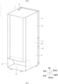
FIG. 1 is a view showing a refrigerating appliance according to an embodiment of the present invention, and is a perspective view of the refrigerating appliance as viewed from the upper rear side. -
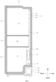
FIG. 2 is a side sectional view showing the refrigerating appliance according to the embodiment of the present invention. -
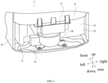
FIG. 3 is a view showing the refrigerating appliance according to the embodiment of the present invention, and is a perspective view of a machinery chamber as viewed from the upper rear side. -
FIG. 4 is a view showing the refrigerating appliance according to the embodiment of the present invention, (A) being an exploded perspective view showing a structure of an electric box in detail, and (B) being a perspective view showing a specific structure of a substrate fixing clamp of the electric box. -
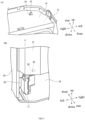
FIG. 5 is a view showing the refrigerating appliance according to the embodiment of the present invention, (A) being a perspective view of a structure in which a protruding insertion portion is inserted into an opening portion as viewed from the front, and (B) being a perspective view of the structure in which the protruding insertion portion is inserted into the opening portion as viewed from the rear. -
FIG. 6 is a view showing the refrigerating appliance according to the embodiment of the present invention, (A) being a perspective view showing a structure in which the electric box is connected in detail, and (B) being an upper sectional view showing the structure in which the electric box is connected. -
FIG. 7 is a view showing a refrigerating appliance according to the background, (A) being a perspective view of a machinery chamber as viewed from the upper rear side, and (B) being a perspective view of a position where an electric box is connected as viewed from the lower rear side. -
FIG. 8 is a view showing the refrigerating appliance according to the background, (A) being an upper sectional view of a position where the electric box is connected, and (B) being an upper sectional view showing a state where the electric box is displaced. - 10: refrigerating appliance, 11: heat insulation cabinet, 111: outer cabinet, 112: inner cabinet, 113: heat insulation material, 114: vegetable chamber, 115: cooling chamber, 116: evaporator, 117: defrosting heater, 118: air supply path, 12: refrigerating chamber, 13: freezing chamber, 14: machinery chamber, 15: machinery chamber opening, 16: terminal cover, 17: electric box, 171: substrate housing, 172: substrate, 173: substrate fixing clamp, 174: substrate support, 175: screw, 18: heat insulation door, 19: heat insulation door, 20: heat insulation door, 21: outer-cabinet rear surface, 22: compressor, 23: outer-cabinet side surface, 24: upper surface member, 25: protruding insertion portion, 251: sharp portion, 252: rib, 26: opening portion, 27: evaporating dish, 28: refrigerant pipe, 29: connecting portion, 100: refrigerating appliance, 101: heat insulation cabinet, 102: machinery chamber, 103: compressor, 104: outer-cabinet rear surface, 105: electric box, 106: screw, 107: outer-cabinet side surface, 108: refrigerant pipe.
- Hereinafter, a refrigerating
appliance 10 according to an embodiment of the present invention will be described in detail based on the accompanying drawings. Further, in describing the present embodiment, the same reference numerals are used for the same members in principle, and redundant descriptions are omitted. In the present embodiment, the description is given using an up-down direction, a front-rear direction and a left-right direction, and the left-right direction refers to the left-right direction when the refrigeratingappliance 10 is viewed from the rear. Furthermore, in the present embodiment, a refrigerating appliance having a freezing chamber and a refrigerating chamber is exemplified as the refrigeratingappliance 10, but the refrigeratingappliance 10 may be configured as a refrigerating appliance having only a freezing chamber or only a refrigerating chamber. -
FIG. 1 is a perspective view of the refrigeratingappliance 10 according to the embodiment of the present invention as viewed from the upper rear side. The refrigeratingappliance 10 has aheat insulation cabinet 11 and a storage chamber formed inside theheat insulation cabinet 11. As the storage chamber, there exist a refrigeratingchamber 12, avegetable chamber 114, and afreezing chamber 13. A front opening of the refrigeratingchamber 12 is closed by a rotaryheat insulation door 18, a front opening of thevegetable chamber 114 is closed by a drawnheat insulation door 19, and a front surface opening of thefreezing chamber 13 is closed by a drawnheat insulation door 20. - A
machinery chamber 14 as a cavity is formed at a bottom of a rear side of the refrigeratingappliance 10. Themachinery chamber 14 is formed continuously from a left end to a right end of theheat insulation cabinet 11. InFIG. 1 , structural apparatuses built in themachinery chamber 14 are not shown. A machinery chamber opening 15 which opens rearwards is formed in themachinery chamber 14. The machinery chamber opening 15 may also be blocked by a cover. -
FIG. 2 is a side sectional view of the refrigeratingappliance 10. Referring to the drawing, theheat insulation cabinet 11 includes anouter cabinet 111, aninner cabinet 112 and aheat insulation material 113, theouter cabinet 111 is formed by bending a steel plate into a prescribed shape, theinner cabinet 112 is formed by a synthetic resin plate spaced apart from theouter cabinet 111 and located on an inner side of theouter cabinet 111, and theheat insulation material 113 is packed between theouter cabinet 111 and theinner cabinet 112. - A cooling chamber 115 is defined and formed on an inner side of the freezing
chamber 13, and anevaporator 116 is received in the cooling chamber 115. An air supply path 118 is formed above the cooling chamber 115. Air is blown into the air supply path 118 by a cold air blowing fan not shown, and the air is cooled by theevaporator 116 in the cooling chamber 115. The air cooled by theevaporator 116 is also blown to the freezingchamber 13. - A
defrosting heater 117 is configured inside the cooling chamber 115, and thedefrosting heater 117 is located below theevaporator 116. Thedefrosting heater 117 is configured as a heater which generates heat by energization, and generates heat when energized during a defrosting stroke, and frost of theevaporator 116 is molten by the generated heat. Defrosted water generated by the defrosting reaches an evaporatingdish 27 described later with reference toFIG. 3 , and is evaporated by heat exchange with a high-temperature compressed refrigerant or acompressor 22. -
FIG. 3 is a perspective view of themachinery chamber 14 as viewed from the upper rear side. Thecompressor 22, aterminal cover 16, anelectric box 17, and the evaporatingdish 27 are configured inside themachinery chamber 14. InFIG. 3 , other members, such as a refrigerant pipe, or the like, which are received in themachinery chamber 14 are not illustrated. - The
terminal cover 16 is formed by a synthetic resin plate shaped into a prescribed shape, is configured on a left side of thecompressor 22, and covers electrodes formed in thecompressor 22. - The
electric box 17 is fixed to a left side surface of themachinery chamber 14, and receives a control board, a capacitor for thecompressor 22, or the like. - The evaporating
dish 27 is configured above thecompressor 22 to store the defrosted water generated during the defrosting stroke. -
FIG. 4(A) is an exploded perspective view showing a structure of theelectric box 17 in detail, andFIG. 4(B) is a perspective view showing a structure of asubstrate fixing clamp 173 of theelectric box 17. - Referring to
FIG. 4(A) , theelectric box 17 has asubstrate housing 171, asubstrate 172, and thesubstrate fixing clamp 173. - The
substrate housing 171 and thesubstrate fixing clamp 173 are formed by injection-molded synthetic resin or metal plates, and thesubstrate housing 171 and thesubstrate fixing clamp 173 are engaged with each other to form a box shape. Thesubstrate 172 is placed inside thesubstrate housing 171 and thesubstrate fixing clamp 173. - The
substrate 172 is formed by, for example, a glass epoxy substrate, or the like, and is provided with an electrical circuit for controlling the apparatuses forming the refrigerating cycle. For example, circuit elements, such as capacitors, or the like, are mounted on a surface of thesubstrate 172. - A left side of the
substrate fixing clamp 173 is fixed to a side surface of themachinery chamber 14 by ascrew 175. Specifically, the left side of thesubstrate fixing clamp 173 is fixed to a rear side of an outer-cabinet side surface 23, which forms an inner wall of themachinery chamber 14. Furthermore, a part of thesubstrate fixing clamp 173 into which thescrew 175 is inserted is reinforced by asubstrate support 174. - Referring to
FIG. 4(B) , a rear upper end portion of thesubstrate fixing clamp 173 protrudes upwards to form a protrudinginsertion portion 25. The protrudinginsertion portion 25 and a body part of the injection-moldedsubstrate fixing clamp 173 are integrally formed, for example. Furthermore, the protrudinginsertion portion 25 has asharp portion 251 and arib 252. Thesharp portion 251 is configured as a portion where an upper end of the protrudinginsertion portion 25 is sharply formed. By providing thesharp portion 251, a front end portion of the protrudinginsertion portion 25 can be easily inserted into theheat insulation material 113 as described later. Furthermore, therib 252 is configured as a portion where both end portions of the protrudinginsertion portion 25 in the left-right direction are thickened. Therib 252 is continuously formed from a lower end to the vicinity of an upper end of the protrudinginsertion portion 25. By forming therib 252, the protrudinginsertion portion 25 can be reinforced, thereby preventing damage or deformation of the protrudinginsertion portion 25 when an external force acts on the protrudinginsertion portion 25. -
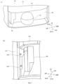
FIG. 5(A) is a perspective view of a structure in which the protrudinginsertion portion 25 is inserted into an openingportion 26 as viewed from the front, andFIG. 5(B) is a perspective view of the structure in which the protrudinginsertion portion 25 is inserted into the openingportion 26 as viewed from the rear. - Referring to
FIG. 5(A) , anupper surface member 24 is formed on an upper surface of themachinery chamber 14. Theupper surface member 24 is formed by a steel plate formed into a prescribed shape, and forms a part of theouter cabinet 111 shown inFIG. 2 . - The opening
portion 26 is formed by opening a part of theupper surface member 24 in a substantially rectangular shape. The protrudinginsertion portion 25 is inserted into the openingportion 26 from a bottom. A part of the protrudinginsertion portion 25 protruding upwards from the openingportion 26 is embedded in theheat insulation material 113 shown inFIG. 2 . - Referring to
FIG. 5(B) , a left end portion of theelectric box 17 is fixed to a side surface of the outer-cabinet side surface 23, which forms a left side surface of themachinery chamber 14, by a connectingportion 29. Furthermore, the protrudinginsertion portion 25 is inserted into the openingportion 26, and the protrudinginsertion portion 25 is formed at a right end portion of theelectric box 17. In this way, both end portions of theelectric box 17 in a width direction are fixed to theheat insulation cabinet 11, thereby suppressing movement of theelectric box 17 inside themachinery chamber 14. -
FIG. 6(A) is a perspective view showing a structure in which theelectric box 17 is connected in detail, andFIG. 6(B) is an upper sectional view showing the structure in which theelectric box 17 is connected. - Referring to
FIG. 6(B) , arefrigerant pipe 28 is placed between theelectric box 17 and the outer-cabinet side surface 23. Therefrigerant pipe 28 is configured as a pipe made of metal, such as copper, or the like, through which a refrigerant used in the refrigerating cycle flows. - As described above, in a manufacturing process of the refrigerating
appliance 10, there exist operations of drawing therefrigerant pipe 28 out of themachinery chamber 14 for welding, and then returning therefrigerant pipe 28 to themachinery chamber 14. At this point, therefrigerant pipe 28 sometimes deviates from a normal position. Here, a case where therefrigerant pipe 28 deviates from the normal position and a rear portion thereof is configured on a right side is shown. In this case, a rear end of therefrigerant pipe 28 leftwards presses a rear portion of theelectric box 17. - In the present embodiment, as shown in
FIG. 6(A) , a left end portion of theelectric box 17 is fixed to the outer-cabinet side surface 23 by 2screws 175. Furthermore, at the right end portion of theelectric box 17, the protrudinginsertion portion 25 is inserted into the openingportion 26. Further, as shown inFIG. 6(B) , therefrigerant pipe 28 is configured on a right side of theelectric box 17, and the protrudinginsertion portion 25 is formed on a left side of theelectric box 17. - Thus, the
electric box 17 is firmly fixed to theheat insulation cabinet 11 side, and therefore, even when the incorrectly-configuredrefrigerant pipe 28 presses theelectric box 17, the movement of theelectric box 17 is suppressed. Therefore, any part of theelectric box 17 can be prevented from protruding outside an outer-cabinetrear surface 21. - The following main effects can be achieved by the above-mentioned embodiments.
- According to the present embodiment, by inserting the protruding
insertion portion 25 into the openingportion 26, the inadvertent movement of theelectric box 17 inside themachinery chamber 14 can be suppressed, the protrudinginsertion portion 25 is provided by forming a part of theelectric box 17 into the protruding shape, and the openingportion 26 is formed on the inner surface of themachinery chamber 14. - Further, the protruding
insertion portion 25 is configured at a position apart from the connectingportion 29, such that the effect of suppressing the movement of theelectric box 17 by the protrudinginsertion portion 25 can be remarkable. - Further, even when the
electric box 17 is pressed by therefrigerant pipe 28, the movement of theelectric box 17 can be suppressed by inserting the protrudinginsertion portion 25 into the openingportion 26 at a position apart from therefrigerant pipe 28. - In addition, by embedding the front end portion of the protruding
insertion portion 25 into theheat insulation material 113, the protrudinginsertion portion 25 can be firmly fixed to theheat insulation cabinet 11 side, thereby making an effect of supporting theelectric box 17 remarkable. - The present invention is not limited to the above embodiments, and various modifications can be made without departing from the scope of the present invention.
Claims (10)
- A refrigerating appliance, comprising:a machinery chamber defined and formed in a heat insulation cabinet; andan electric box received in the machinery chamber,wherein one end of the electric box is connected to a side surface of the machinery chamber by a connecting portion,a protruding insertion portion is inserted into an opening portion, the protruding insertion portion is provided by forming a part of the electric box into a protruding shape, and the opening portion is formed in an inner surface of the machinery chamber.
- The refrigerating appliance according to claim 1,wherein the connecting portion is configured on one end side of the electric box, andthe protruding insertion portion is configured on an end side of the electric box opposite to the connecting portion.
- The refrigerating appliance according to claim 1,wherein a refrigerant pipe is configured in the machinery chamber near the electric box, andthe protruding insertion portion is configured at an end portion of a side of the electric box apart from the refrigerant pipe.
- The refrigerating appliance according to claim 1,wherein the heat insulation cabinet comprises an outer cabinet, an inner cabinet, and a heat insulation material packed between the outer cabinet and the inner cabinet, anda front end portion of the protruding insertion portion is embedded in the heat insulation material.
- The refrigerating appliance according to claim 1, wherein the electric box has a substrate housing, a substrate and a substrate fixing clamp, and the protruding insertion portion and a body part of the substrate fixing clamp are integrally formed.
- The refrigerating appliance according to claim 1, wherein the protruding insertion portion has a sharp portion and a rib.
- The refrigerating appliance according to claim 6, wherein the sharp portion is configured as a portion where an upper end of the protruding insertion portion is sharply formed, and the rib is configured as a portion where both end portions of the protruding insertion portion in a left-right direction are thickened.
- The refrigerating appliance according to claim 1, wherein an upper surface member is formed on an upper surface of the machinery chamber, and the opening portion is formed by opening a part of the upper surface member.
- The refrigerating appliance according to claim 1, wherein a compressor, the electric box and an evaporating dish are configured inside the machinery chamber.
- The refrigerating appliance according to claim 1, wherein the electric box is fixed to a left side surface of the machinery chamber, and the evaporating dish is configured above the compressor.
Applications Claiming Priority (2)
| Application Number | Priority Date | Filing Date | Title |
|---|---|---|---|
| JP2020173106A JP7505755B2 (en) | 2020-10-14 | 2020-10-14 | refrigerator |
| PCT/CN2021/123602 WO2022078405A1 (en) | 2020-10-14 | 2021-10-13 | Refrigeration appliance |
Publications (2)
| Publication Number | Publication Date |
|---|---|
| EP4206596A1 true EP4206596A1 (en) | 2023-07-05 |
| EP4206596A4 EP4206596A4 (en) | 2024-02-21 |
Family
ID=81207736
Family Applications (1)
| Application Number | Title | Priority Date | Filing Date |
|---|---|---|---|
| EP21879448.5A Pending EP4206596A4 (en) | 2020-10-14 | 2021-10-13 | COOLER |
Country Status (4)
| Country | Link |
|---|---|
| EP (1) | EP4206596A4 (en) |
| JP (1) | JP7505755B2 (en) |
| CN (1) | CN116368337A (en) |
| WO (1) | WO2022078405A1 (en) |
Family Cites Families (9)
| Publication number | Priority date | Publication date | Assignee | Title |
|---|---|---|---|---|
| JP2002162158A (en) * | 2000-11-21 | 2002-06-07 | Toshiba Corp | refrigerator |
| CN1784126A (en) * | 2004-11-29 | 2006-06-07 | 乐金电子(天津)电器有限公司 | Fixing structure of control box |
| CN102230710B (en) * | 2011-05-25 | 2012-11-28 | 合肥美的荣事达电冰箱有限公司 | Evaporation disk and refrigerator comprising same |
| JP6092719B2 (en) | 2013-06-17 | 2017-03-08 | アクア株式会社 | refrigerator |
| CN203837402U (en) * | 2014-04-28 | 2014-09-17 | 合肥晶弘电器有限公司 | Refrigerator main control board mounting structure and refrigerator |
| CN105737505A (en) * | 2014-12-10 | 2016-07-06 | 博西华电器(江苏)有限公司 | Refrigerator |
| CN105091480B (en) | 2015-04-01 | 2017-08-15 | 合肥华凌股份有限公司 | Wet sterilization refrigerator |
| CN106052293A (en) * | 2016-05-25 | 2016-10-26 | 合肥华凌股份有限公司 | Main control board installing structure and refrigerator |
| JP7268832B2 (en) | 2018-12-25 | 2023-05-08 | アクア株式会社 | refrigerator |
-
2020
- 2020-10-14 JP JP2020173106A patent/JP7505755B2/en active Active
-
2021
- 2021-10-13 EP EP21879448.5A patent/EP4206596A4/en active Pending
- 2021-10-13 CN CN202180070629.1A patent/CN116368337A/en active Pending
- 2021-10-13 WO PCT/CN2021/123602 patent/WO2022078405A1/en not_active Ceased
Also Published As
| Publication number | Publication date |
|---|---|
| JP7505755B2 (en) | 2024-06-25 |
| JP2022064463A (en) | 2022-04-26 |
| EP4206596A4 (en) | 2024-02-21 |
| WO2022078405A1 (en) | 2022-04-21 |
| CN116368337A (en) | 2023-06-30 |
Similar Documents
| Publication | Publication Date | Title |
|---|---|---|
| US10047994B2 (en) | Refrigerator and method for assembling ice machine thereof | |
| EP3532781B1 (en) | Skin condenser design integrated in the refrigerator back | |
| EP4206596A1 (en) | Refrigeration appliance | |
| KR101206507B1 (en) | Refrigerator with a withdrawable cooling unit | |
| US9982932B2 (en) | Refrigeration appliance with an ice container | |
| JP7557852B2 (en) | refrigerator | |
| JPH10318655A (en) | Freezer refrigerator | |
| EP3943844B1 (en) | Refrigerator | |
| JP2014222134A (en) | Refrigerator | |
| KR20060030321A (en) | Refrigerator | |
| GB2154722A (en) | Refrigerator | |
| EP4249834B1 (en) | Refrigerator | |
| KR20150024504A (en) | Control box for compressor | |
| KR200256497Y1 (en) | support bracket for an air blower of Kim-Chi storage | |
| KR100441017B1 (en) | Refrigerator for kimchi | |
| KR20040057771A (en) | A fixations structure of lead wire for refrigerators | |
| KR100444967B1 (en) | Refrigerator for kimchi | |
| KR20100066865A (en) | Motor mounting member and tray assembly having this | |
| KR100260726B1 (en) | Refrigerator | |
| KR200184323Y1 (en) | Attachment apparatus for heat exchanger of refrigerator | |
| KR20100085262A (en) | Stand type kimchi-refrigerator | |
| JP3650015B2 (en) | Chiller defroster | |
| KR0124288Y1 (en) | Evaporating plate | |
| KR200235173Y1 (en) | Refrigerator box | |
| KR100229470B1 (en) | Refrigerator having an evaporator |
Legal Events
| Date | Code | Title | Description |
|---|---|---|---|
| STAA | Information on the status of an ep patent application or granted ep patent |
Free format text: STATUS: THE INTERNATIONAL PUBLICATION HAS BEEN MADE |
|
| PUAI | Public reference made under article 153(3) epc to a published international application that has entered the european phase |
Free format text: ORIGINAL CODE: 0009012 |
|
| STAA | Information on the status of an ep patent application or granted ep patent |
Free format text: STATUS: REQUEST FOR EXAMINATION WAS MADE |
|
| 17P | Request for examination filed |
Effective date: 20230328 |
|
| AK | Designated contracting states |
Kind code of ref document: A1 Designated state(s): AL AT BE BG CH CY CZ DE DK EE ES FI FR GB GR HR HU IE IS IT LI LT LU LV MC MK MT NL NO PL PT RO RS SE SI SK SM TR |
|
| DAV | Request for validation of the european patent (deleted) | ||
| DAX | Request for extension of the european patent (deleted) | ||
| A4 | Supplementary search report drawn up and despatched |
Effective date: 20240122 |
|
| RIC1 | Information provided on ipc code assigned before grant |
Ipc: F25D 19/00 20060101ALI20240116BHEP Ipc: F25D 29/00 20060101AFI20240116BHEP |
|
| GRAP | Despatch of communication of intention to grant a patent |
Free format text: ORIGINAL CODE: EPIDOSNIGR1 |
|
| STAA | Information on the status of an ep patent application or granted ep patent |
Free format text: STATUS: GRANT OF PATENT IS INTENDED |
|
| INTG | Intention to grant announced |
Effective date: 20251020 |