EP4206577A1 - Ice-making device and refrigeration apparatus - Google Patents
Ice-making device and refrigeration apparatus Download PDFInfo
- Publication number
- EP4206577A1 EP4206577A1 EP21939587.8A EP21939587A EP4206577A1 EP 4206577 A1 EP4206577 A1 EP 4206577A1 EP 21939587 A EP21939587 A EP 21939587A EP 4206577 A1 EP4206577 A1 EP 4206577A1
- Authority
- EP
- European Patent Office
- Prior art keywords
- ice
- making
- operating member
- limiting
- boxes
- Prior art date
- Legal status (The legal status is an assumption and is not a legal conclusion. Google has not performed a legal analysis and makes no representation as to the accuracy of the status listed.)
- Granted
Links
Images


Classifications
-
- F—MECHANICAL ENGINEERING; LIGHTING; HEATING; WEAPONS; BLASTING
- F25—REFRIGERATION OR COOLING; COMBINED HEATING AND REFRIGERATION SYSTEMS; HEAT PUMP SYSTEMS; MANUFACTURE OR STORAGE OF ICE; LIQUEFACTION SOLIDIFICATION OF GASES
- F25C—PRODUCING, WORKING OR HANDLING ICE
- F25C1/00—Producing ice
- F25C1/10—Producing ice by using rotating or otherwise moving moulds
-
- F—MECHANICAL ENGINEERING; LIGHTING; HEATING; WEAPONS; BLASTING
- F25—REFRIGERATION OR COOLING; COMBINED HEATING AND REFRIGERATION SYSTEMS; HEAT PUMP SYSTEMS; MANUFACTURE OR STORAGE OF ICE; LIQUEFACTION SOLIDIFICATION OF GASES
- F25C—PRODUCING, WORKING OR HANDLING ICE
- F25C1/00—Producing ice
- F25C1/04—Producing ice by using stationary moulds
-
- F—MECHANICAL ENGINEERING; LIGHTING; HEATING; WEAPONS; BLASTING
- F25—REFRIGERATION OR COOLING; COMBINED HEATING AND REFRIGERATION SYSTEMS; HEAT PUMP SYSTEMS; MANUFACTURE OR STORAGE OF ICE; LIQUEFACTION SOLIDIFICATION OF GASES
- F25C—PRODUCING, WORKING OR HANDLING ICE
- F25C5/00—Working or handling ice
- F25C5/02—Apparatus for disintegrating, removing or harvesting ice
- F25C5/04—Apparatus for disintegrating, removing or harvesting ice without the use of saws
-
- F—MECHANICAL ENGINEERING; LIGHTING; HEATING; WEAPONS; BLASTING
- F25—REFRIGERATION OR COOLING; COMBINED HEATING AND REFRIGERATION SYSTEMS; HEAT PUMP SYSTEMS; MANUFACTURE OR STORAGE OF ICE; LIQUEFACTION SOLIDIFICATION OF GASES
- F25C—PRODUCING, WORKING OR HANDLING ICE
- F25C5/00—Working or handling ice
- F25C5/20—Distributing ice
- F25C5/22—Distributing ice particularly adapted for household refrigerators
-
- F—MECHANICAL ENGINEERING; LIGHTING; HEATING; WEAPONS; BLASTING
- F25—REFRIGERATION OR COOLING; COMBINED HEATING AND REFRIGERATION SYSTEMS; HEAT PUMP SYSTEMS; MANUFACTURE OR STORAGE OF ICE; LIQUEFACTION SOLIDIFICATION OF GASES
- F25C—PRODUCING, WORKING OR HANDLING ICE
- F25C2400/00—Auxiliary features or devices for producing, working or handling ice
- F25C2400/06—Multiple ice moulds or trays therefor
-
- F—MECHANICAL ENGINEERING; LIGHTING; HEATING; WEAPONS; BLASTING
- F25—REFRIGERATION OR COOLING; COMBINED HEATING AND REFRIGERATION SYSTEMS; HEAT PUMP SYSTEMS; MANUFACTURE OR STORAGE OF ICE; LIQUEFACTION SOLIDIFICATION OF GASES
- F25C—PRODUCING, WORKING OR HANDLING ICE
- F25C2400/00—Auxiliary features or devices for producing, working or handling ice
- F25C2400/10—Refrigerator units
Definitions
- the present application relates to the field of ice-making, in particular to an ice-making device and a refrigeration machine.
- ice-making devices are mainly used for preparation of ice cubes, de-icing and storage.
- De-icing is usually performed by using gear and rack transmission modes, which enables the gear and rack transmission modes to be very complicated.
- each ice-making box performs de-icing independently, which brings inconvenience to users.
- some ice-making boxes are not detachable and some ice-making boxes need to be disassembled using professional tools. After the ice-making device is used for a period of time, in order to keep the ice-making boxes clean, the user needs to disassemble the ice-making device to clean the ice-making boxes, which causes certain inconvenience by the above two installation methods.
- the present application is intended to solve at least one of the problems in the related art. Therefore, the present application provides an ice-making device capable of improving the de-icing efficiency of ice-making boxes.
- the present application further provides refrigeration machine.
- the operating member and the plurality of ice-making boxes are connected by using a connector, while a plurality of releasing holes and limiting holes communicating with each other are arranged on the connector, and the connector can be switched between the releasing position and the limiting position.
- the connector is at the releasing position, the operating member and the plurality of ice-making boxes are connected to the releasing holes and can act axially relative to the releasing holes to release from the releasing holes, and thus the operating member and the plurality of ice-making boxes can be disassembled along the axial direction of the releasing holes.
- the connector When the connector is at the limiting position, the operating member and the plurality of ice-making boxes are connected to the limiting holes, and thus the connector can be axially limited, and thus the operating member and the plurality of ice-making boxes can be mounted in a linkage manner. In this way, the user only needs to adjust the position of the connector to disassemble and assemble the operating member and the plurality of ice-making boxes, which improves the disassembly and assembly efficiency of the ice-making boxes and is convenient for the user to clean the plurality of ice-making boxes.
- the user can invert the plurality of ice-making boxes only by rotating the operating member, the steps of de-icing for each ice-making box separately in the related art are eliminated, and the de-icing efficiency of the plurality of ice-making boxes is improved.
- the bracket includes a panel and a frame connected to the panel, where the operating member is rotatably connected to the panel, and the plurality of ice-making boxes are rotatably connected to the frame.
- an aperture of each of the releasing holes is larger than an aperture of each of the limiting holes, and a transition section is provided between each of the releasing holes and each of the limiting holes, and an aperture at the transition section is smaller than an aperture of the limiting hole.
- each ice-making box is provided with a second connecting column which includes a second connecting section and a second limiting section.
- a diameter of the second connecting section is matched with an aperture of the releasing hole, and a diameter of the second limiting section is matched with an aperture of the limiting hole.
- the second limiting section is provided with a second transition surface for passing the second limiting section through the transition section.
- two opposite ends of the frame are provided with assembly holes configured to mount the plurality of ice-making boxes, and the plurality of ice-making boxes are provided with installation columns configured to be installed in the plurality of assembly holes.
- the frame is provided with a stopper bar, and the stopper bar abuts against ice trays of the plurality of ice-making boxes to limit a swivel angle of the plurality of ice-making boxes relative to the frame.
- each installation column is sleeved with a reset member configured to switch the plurality of ice-making boxes from a de-icing state to an ice-making state, and two ends of the reset member abut against the plurality of ice-making boxes and the frame, respectively.
- the operating member is provided with a first connecting column comprising a first connecting section and a first limiting section.
- a diameter of the first connecting section is matched with an aperture of the releasing hole, and a diameter of the first limiting section is matched with an aperture of the limiting hole.
- the first limiting section is provided with a first transition surface for passing the first limiting section through the transition section.
- the panel is provided with a through hole and a guide groove, where the operating member is provided with a connecting head in rotation-match with the through hole, and the first connecting column is adapted to pass through the guide groove to connect to the connector.
- the ice making device further includes an ice storage box arranged below the bracket and corresponding to the plurality of ice-making boxes.
- the ice making device further includes a housing, and the bracket and the ice storage box are movably mounted on the housing.
- the refrigeration machine includes a cabinet body and the ice-making device mentioned above, and the ice-making device is arranged in the cabinet body.
- the de-icing efficiency of the ice-making box can be improved by arranging the ice-making device mentioned above in the cabinet body, and it is convenient for the user to assemble and disassemble the plurality of ice-making boxes to facilitate the user to clean the plurality of ice-making boxes.
- the operating member and the plurality of ice-making boxes are connected by using a connector, while a plurality of releasing holes and limiting holes communicating with each other are arranged on the connector, and the connector can be switched between the releasing position and the limiting position.
- the connector When the connector is at the releasing position, the operating member and the plurality of ice-making boxes are connected to the releasing holes and can act axially relative to the releasing holes to loose from the releasing holes, and thus the operating member and the plurality of ice-making boxes can be disassembled along the axial direction of the releasing holes.
- the connector When the connector is at the limiting position, the operating member and the plurality of ice-making boxes are connected to the limiting holes, and thus the connector can be axially limited, and thus the operating member and the plurality of ice-making boxes can be mounted in a linkage manner. In this way, the user only needs to adjust the position of the connector to disassemble and assemble the operating member and the plurality of ice-making boxes, which improves the disassembly and assembly efficiency of the ice-making boxes and is convenient for the user to clean the plurality of ice-making boxes.
- the user can invert the plurality of ice-making boxes only by rotating the operating member, the steps of de-icing for each ice-making box separately in the related art are eliminated, and the de-icing efficiency of the plurality of ice-making boxes is improved.
- the de-icing efficiency of the ice-making box can be improved by arranging the ice-making device mentioned above in the cabinet body, and it is convenient for the user to assemble and disassemble the ice-making box to facilitate the user to clean the ice-making box.
- 100 bracket; 102: ice-making box; 104: operating member; 106: connector; 108: releasing hole; 110: limiting hole; 112: panel; 114: frame; 116: transition section; 118: first connecting column; 120: first connecting section; 122: first limiting section; 124: first transition surface; 126: through hole; 128: guide groove; 130: connecting head; 132: second connecting column; 134: second connecting section; 136: second limiting section; 138: second transition surface; 140: assembly hole; 142: installation column; 144: ice storage box; 146: housing; 148: torsion spring; 150: stopper bar; 152: supporting structure; 154: limiting protrusion; 156: limiting boss; 158: handle structure.
- connection to and “connected” shall be understood broadly, for example, it may be either fixedly connected or detachably connected, or can be integrated; it may be either mechanically connected, or electrically connected; it may be either directly connected, or indirectly connected through an intermediate medium.
- connection to and “connected” shall be understood broadly, for example, it may be either fixedly connected or detachably connected, or can be integrated; it may be either mechanically connected, or electrically connected; it may be either directly connected, or indirectly connected through an intermediate medium.
- a first feature is "on” or “under” a second feature can refer to that the first feature is directly contacted with the second feature, or the first feature is indirectly contacted with the second feature through an intermediate medium.
- the first feature is "on”, “above” and “over” the second feature can refer to that the first feature is directly above or obliquely above the second feature, or simply refer to that the level height of the first feature is higher than level height of the second feature.
- the first feature is "under”, “below” and “beneath” the second feature can refer to that the first feature is directly below or obliquely below the second feature, or simply refer to that the level height of the first feature is lower than level height of the second feature.
- an embodiment of the present application provides an ice-making device, including a bracket 100, an operating member 104 and a connector 106; where the bracket 100 is provided with a plurality of ice-making boxes 102; the operating member 104 is mounted on the bracket 100; and the connector 106 is connected between the operating member 104 and the plurality of ice-making boxes 102 and thus the operating member 104 drives the plurality of ice-making boxes 102 to act; where the connector 106 is provided with a plurality of releasing holes 108 and limiting holes 110 being in one-to-one correspondence with the operating member 104 and the plurality of ice-making boxes 102 and communicating with each other; the connector 106 is switched between a releasing position at which the operating member 104 and the plurality of ice-making boxes 102 are respectively connected to the releasing holes 108 and are disassembled from the releasing holes 108, and a limiting position at which the operating member 104 and the plurality of ice-making boxes
- the operating member 104 and the plurality of ice-making boxes 102 are connected by using a connector 106, while a plurality of releasing holes 108 and limiting holes 110 communicating with each other are arranged on the connector 106, and the connector 106 can be switched between the releasing position and the limiting position.
- the connector 106 is at the releasing position, the operating member 104 and the plurality of ice-making boxes 102 are connected to the releasing holes 108 and can act axially relative to the releasing holes 108 to release from the releasing holes 108, and thus the operating member 104 and the plurality of ice-making boxes 102 can be disassembled along the axial direction of the releasing holes 108.
- the connector 106 When the connector 106 is at the limiting position, the operating member 104 and the plurality of ice-making boxes 102 are connected to the limiting holes 110, and thus the connector 106 can be axially limited, and thus the operating member 104 and the plurality of ice-making boxes 102 can be mounted in a linkage manner. In this way, the user only needs to adjust the position of the connector 106 to disassemble and assemble the operating member 104 and the plurality of ice-making boxes 102, which improves the disassembly and assembly efficiency of the ice-making boxes 102 and is convenient for the user to clean the plurality of ice-making boxes 102.
- the user can invert the plurality of ice-making boxes 102 only by rotating the operating member 104, the steps of de-icing for each ice-making box 102 separately in the related art are eliminated, and the de-icing efficiency of the plurality of ice-making boxes 102 is improved.
- the operating member 104 and the plurality of ice-making boxes 102 are mounted on the bracket 100 by using the connector 106, while a plurality of releasing holes 108 and limiting holes 110 communicating with each other are arranged on the connector 106, and the connector 106 can be switched between the releasing position and the limiting position.
- the connector 106 is at the releasing position, the operating member 104 and the plurality of ice-making boxes 102 are connected to the releasing holes 108 and can act axially relative to the releasing holes 108 to release from the releasing holes 108, and thus the operating member 104 and the plurality of ice-making boxes 102 can be disassembled along the axial direction of the releasing holes 108.
- the operating member 104 and the ice-making boxes 102 are connected to the limiting holes 110, and thus the operating member 104 and the ice-making boxes 102 can be mounted in a linkage manner.
- the user only needs to adjust the position of the connector 106 to disassemble and assemble the operating member 104 and the ice-making boxes 102, which improves the disassembly and assembly efficiency of the ice-making boxes 102 and is convenient for the user to clean the ice-making boxes 102.
- the number of ice-making boxes 102 is plurality, and the plurality of ice-making boxes 102 can be connected to the connector 106. In this case, the plurality of ice-making boxes 102 can be inverted only by the connector 106, and thus de-icing is performed efficiently.
- the ice-making device mainly includes a bracket 100, an operating member 104 and a connector 106.
- the bracket 100 is used to support the ice-making boxes 102 and mount the operating member 104.
- the operating member 104 is used to facilitate the user to swivel and de-ice the ice-making boxes 102.
- the connector 106 is used to connect the operating member 104 and the plurality of ice-making boxes 102 and thus the operating member 104 can simultaneously drive the plurality of ice-making boxes 102 for de-icing.
- the bracket 100 includes a panel 112 and a frame 114 connected to the panel 112, where the frame 114 is roughly a rectangular and mounted on a side of the panel 112.
- the operating member 104 is rotatably connected to the panel 112, the number of the ice-making boxes 102 is plurality, and the plurality of ice-making boxes 102 are rotatably connected to the frame 114.
- the panel 112 is provided with a through hole 126
- the operating member 104 is provided with a connecting head 130 in rotation-match with the through hole 126.
- An end of the connecting head 130 on the operating member 104 is provided with one or more claws.
- the plurality of ice-making boxes 102 can swivel relative to the frame 114.
- the number of the ice-making boxes 102 is two and the two ice-making boxes 102 are arranged side by side on the frame 114 and can swivel relative to the frame 114.
- two opposite ends of the frame 114 are provided with assembly holes 140 used for mounting the ice-making boxes 102.
- the assembly holes 140 can be provided at an end of the frame 114 proximal to the panel 112 and an end of the frame 114 away from the panel 112.
- the assembly hole 140 on the end of the frame 114 proximal to the panel 112 is an assembly hole 140 with an opening
- the assembly hole 140 on the end of the frame 114 away from the panel 112 is a fully closed assembly hole 140.
- two opposite ends of the ice-making boxes 102 are provided with installation columns 142 used for installing in the assembly hole 140.
- the installation column 142 at an end of the ice-making boxes 102 can be inserted into the fully closed assembly hole 140, and then the installation column 142 at another end of the ice-making boxes 102 can be inserted into the assembly hole 140 with an opening.
- the convenience of mounting the ice-making boxes 102 on the frame 114 can be improved, and the deformation of the ice-making boxes 102 can be reduced, and the fully closed assembly hole 140 can effectively prevent the installation column 142 from falling out.
- the installation column 142 located in the assembly hole 140 with an opening can be taken out first, and then the installation column 142 in the fully closed assembly hole 140 can be taken out.
- an end of the installation column 142 is provided with a limiting boss 156.
- An axial action of the ice-making boxes 102 relative to the assembly hole 140 can be limited by abutting the limiting boss 156 against an end surface of the assembly hole 140 with an opening.
- all assembly holes 140 can be set as fully closed assembly holes 140, or all assembly holes 140 can be set as assembly holes 140 with opening.
- an end of the frame 114 away from the panel 112 is provided with stopper bars 150, and for example, the stopper bars 150 can be provided on an inner wall of the frame 114.
- the stopper bars 150 can be provided on an inner wall of the frame 114.
- the outer wall of the ice trays on the ice-making boxes 102 can abut against the stopper bar 150 to limit the swivel angle of the ice-making boxes 102.
- the number of the stopper bars 150 corresponds to the number of the ice-making boxes 102.
- the ice-making boxes 102 can be made of materials with certain deformation, such as polypropylene, acrylonitrile, butadiene, styrene three monomers of terpolymer or engineering plastics, etc.
- the installation column 142 of each ice-making box 102 is sleeved with a reset member.
- the reset member can be a torsion spring 148, where an end of the torsion spring 148 abuts tightly against the ice-making box 102, and another end of the torsion spring 148 abuts tightly against the frame 114.
- an end of the torsion spring 148 can abut tightly against the bottom of the ice-making box 102, and the another end of the torsion spring 148 can abut tightly against the stopper bar 150.
- two stopper bars 150 can be arranged along the height direction of the frame 114, and the another end of the torsion spring 148 can be bent to form a bending section capable of being inserted a gap between the two stopper bars 150.
- the operating member 104 can drive the ice-making boxes 102 to be switched from the ice-making state to the de-icing state through the connector 106. After the de-icing operation is completed, the ice-making boxes 102 can be switched from the de-icing state to the ice-making state under the elastic restoring force of the torsion spring 148.
- the torsion spring 148 is not essential and the ice-making boxes 102 can be de-iced and reset only by the user swivels the operating member 104.
- the bottom of one end of the frame 114 away from the panel 112 is provided with a supporting structure 152, where the bottom of the supporting structure 152 is flush with the bottom of the panel 112.
- the bracket 100 can be stably placed on a table through being supported by the bottom of the panel 112 and the bottom of the supporting structure 152 to prevent water overflow.
- water when it is needed to pour water to the ice-making boxes 102, water can be injected into the ice-making box 102 through the water injection hole at the top of the housing 146, which saves the step of taking out the ice-making box 102 and improves the ice-making efficiency.
- the ice-making device further includes ice storage box 144 arranged below the bracket 100 and corresponding to the ice-making boxes 102.
- the ice storage box 144 and the bracket 100 are independent to each other, and thus the user can take out the ice storage box 144 separately.
- the ice made in the ice-making box 102 can directly fall into the ice storage box 144 with the swivel of the ice-making box 102.
- the ice storage box 144 can be made of transparent materials.
- a pulling slot can be provided on the ice storage box 144 to facilitate the user to pull out the ice storage box 144.
- the ice-making device further includes a housing 146, where the bracket 100 and the ice storage box 144 are movablely arranged in the housing 146.
- a corresponding slide rail or chute can be provided inside the housing 146.
- An edge of the bracket 100 and an edge of the ice storage box 144 can be directly arranged on the slide rail or inserted in the chute, which can reduce the resistance of the bracket 100 and the ice storage box 144 during the pull-out and push-back process and improve the user's convenience.
- the bottom of the frame 114 can be provided with a limiting protrusion 154, which can ensure that the frame 114 is not easy to slip from the housing 146 when the ice-making device is tilted. Further, by arranging the limiting protrusion 154 at the bottom of the frame 114, it is also possible to reduce the friction between the frame 114 and the slide rail or chute in the housing 146, and facilitate the user to pull the frame 114.
- the operating member 104 and the ice-making box 102 is connected by relying on the connector 106. That is, the connector 106 is arranged between the operating member 104 and the ice-making box 102, and the operating member 104 and the ice-making box 102 can be assembled and disassembled through the cooperation of the connector 106 and the bracket 100.
- a plurality of releasing holes 108 and limiting holes 110 communicating with each other are arranged on the connector 106. It should be noted that both the operating member 104 and the ice-making boxes 102 are connected to the connector 106. Therefore, the numbers of releasing holes 108 and the limiting holes 110 on the connector 106 correspond to the number of the operating members 104 and the ice-making boxes 102. For example, the number of the ice-making boxes 102 is two, the number of the operating member 104 is one, and the number of the corresponding releasing holes 108 and the limiting holes 110 are three, respectively.
- the connector 106 can be switched between the releasing position and the limiting position.
- the operating member 104 and the ice-making boxes 102 are respectively installed in the corresponding releasing holes 108 on the connector 106, and both the operating member 104 and the ice-making boxes 102 can be disassembled from the bracket 100.
- the connector 106 is at the limiting position, the operating member 104 and the ice-making boxes 102 are installed in the corresponding limiting holes 110 on the connector 106, the axial movement of the connector 106 is limited, and the operating member 104 and the ice-making boxes 102 are mounted on the bracket 100.
- the function of the connector 106 is described below in combination with a specific structure of the connector 106.
- the aperture of the releasing hole 108 on the connector 106 is larger than the aperture of the limiting hole 110 on the connector 106, and a transition section 116 is formed between the releasing hole 108 and the limiting hole 110.
- the aperture of the transition section 116 is smaller than the aperture of the limiting hole 110.
- the releasing hole 108 and the limiting hole 110 on the connector 106 can form a structure similar to a gourd hole.
- the aperture of the releasing hole 108 is larger than the aperture of the limiting hole 110, and a transition section 116 is arranged between the releasing hole 108 and the limiting hole 110 to form the transition between the releasing hole 108 and the limiting hole 110. Since the releasing hole 108 and the limiting hole 110 communicate with each other, the transition section 116 has a certain aperture, and the aperture of the transition section 116 is smaller than the aperture of the limiting hole 110.
- both the operating member 104 and the ice-making box 102 are able to move in the axial direction of the releasing hole 108 relative to the connector 106 so that the user can detach the operating member 104 and the ice-making box 102 from the bracket 100.
- the operating member 104 and the ice-making box 102 are installed in the limiting hole 110, the operating member 104 and the ice-making box 102 can be limited by the limiting hole 110, and thus the operating member 104 and the ice-making box 102 are limited in the limiting hole 110.
- the operating member 104 is provided with a first connecting column 118.
- the first connecting column 118 includes a first connecting section 120 and a first limiting section 122.
- the diameter of the first connecting section 120 is matched with the aperture of the releasing hole 108, and the diameter of the first limiting section 122 is matched with the aperture of the limiting hole 110.
- the first connecting column 118 for connecting the connector 106 is arranged at the side of the operating member 104 with the connecting head 130.
- the first connecting column 118 is not a complete cylindrical section structure.
- the root of the first connecting column 118 is a complete cylindrical section, which is part of the first connecting section 120.
- the diameter of the first connection section 120 is equal to or slightly less than the aperture of the releasing hole 108, but it is necessary to ensure that the diameter of the first connection section 120 is greater than the aperture of the limiting hole 110.
- a cylindrical section with a slightly smaller diameter is arranged upward from the first connecting section 120, which is the first limiting section 122, and the diameter of the first limiting section 122 is equal to or slightly less than the aperture of the limiting hole 110.
- a complete cylindrical section is arranged upward from the first limiting section 122, which is another part of the first connecting section 120.
- the first connecting column 118 on the operating member 104 is aligned with the releasing hole 108 on the connector 106. Since the diameter of the first connecting section 120 on the first connecting column 118 is equal to or slightly smaller than the aperture of the releasing hole 108, the operating member 104 can move along the axial direction of the releasing hole 108 and the user can detach the operating member 104 from the panel 112 only by taking out the operating member 104 along the axial direction of the releasing hole 108.
- the connector 106 is at the limiting position, since the operating member 104 is fixed by the panel 112 on the bracket 100, the position of the first connecting column 118 is fixed.
- the first connecting column 118 By pushing the connector 106, the first connecting column 118 can slide into the limiting hole 110 from the releasing hole 108. Since both ends of the first limiting section 122 are provided with the first connecting section 120 having a diameter greater than the aperture of the limiting hole 110, the axial movement of the first connecting column 118 relative to the limiting hole 110 is limited, thereby limiting the axial movement of the connector 106.
- the first limiting section 122 is provided with a first transition surface 124 used for passing the first limiting section 122 through the transition section 116.
- the first transition surface 124 mentioned here can be any one of the plane and wavy surfaces.
- the maximum size between the first transition surface 124 and the outer side of the first limiting section 122 is larger than the aperture of the transition section 116.
- the first limiting section 122 is clipped into the limiting hole 110 after passing through the transition section 116 by means of interference fit, which can prevent the first limiting section 122 from sliding out of the limiting hole 110.
- the first transition surface 124 needs to be swiveled in a direction away from the transition section 116.
- the first connecting column 118 swivels counterclockwise to de-ice, and correspondingly, the first transition surface 124 is arranged in the downward direction on the first limiting section 122.
- the first connecting column 118 swivels clockwise to de-ice, the first transition surface 124 should be arranged in the upward direction on the first limiting section 122. In this case, when the first connecting column 118 swivels, the first transition surface 124 swivels away from the transition section 116, so that the first connecting column 118 can be prevented from disengaging from the limiting hole 110.
- the panel 112 is provided with a guide groove 128, and the first connecting column 118 is adapted to pass through the guide groove 128 to be connected to the connector 106.
- the guide groove 128 is an arc groove. By arranging the guide groove 128, it can provide guidance for the swivel of the first connecting column 118, which ensures the stability when the user turns the operating member 104.
- the operating member 104 can take the connection head 130 as the center of a circle and the distance between the first connecting column 118 and the connection head 130 as the radius, to make that through the guidance of the guide groove 128, the user is more labor-saving for turning the operating member 104, and then the inversion operation of the ice-making box 102 can be completed to rapidly and effortlessly de-ice.
- the operating member 104 only swivels with the connection head 130 as the center of the circle, while the first connecting column 118 swivels eccentrically with the swivel of the operating member 104 relative to the connection head 130. Due to the guiding effect of the guide groove 128 on the first connecting column 118, the motion path of the first connecting column 118 is limited, thereby achieving the labor-saving operation of de-icing.
- the operating member 104 in order to facilitate the user to hold, is provided with a handle structure 158.
- the user can hold the handle structure 158 to apply greater torque to the ice-making box 102, thereby making the de-icing smoother.
- an end of the ice-making box 102 facing the panel 112 is provided with a second connecting column 132.
- the second connecting column 132 includes a second connecting section 134 and a second limiting section 136.
- the diameter of the second connecting section 134 is matched with the aperture of the releasing hole 108, and the diameter of the second limiting section 136 is matched with the aperture of the limiting hole 110.
- the second connecting column 132 used for connecting the connector 106 is arranged at an end of the ice-making box 102 facing the panel 112 in the bracket 100.
- the second connecting column 132 is not a complete cylindrical section structure.
- the root of the second connecting column 132 is a complete cylindrical section, which is part of the second connecting section 134.
- the diameter of the second connection section 134 is equal to or slightly less than the aperture of the releasing hole 108, but it is necessary to ensure that the diameter of the second connection section 134 is greater than the aperture of the limiting hole 110.
- a cylindrical section with a slightly smaller diameter is arranged upward from the second connecting section 134, which is the second limiting section 136.
- the diameter of the second limiting section 136 is equal to or slightly less than the aperture of the limiting hole 110.
- a complete cylindrical section is arranged upward from the second limiting section 136, which is another part of the second connecting section 134. That is, the structure of the second connecting column 132 arranged on the ice-making box 102 is exactly the same as the structure of the first connecting column 118 arranged on the operating member 104.
- the connector 106 when the connector 106 is at the releasing position, the second connecting column 132 on the ice-making box 102 and the releasing hole 108 on the connector 106 are aligned with each other. Since the diameter of the second connecting section 134 on the second connecting column 132 is equal to or slightly smaller than the aperture of the releasing hole 108, the connector 106 can move along the axial direction of the releasing hole 108, and the user can detach the ice-making box 102 from the bracket 100 only by taking out the connector 106 along the axial direction of the releasing hole 108. When the connector 106 is at the limiting position, since the ice-making box 102 is fixed by the frame 114 on the bracket 100, the position of the second connecting column 132 is fixed.
- the second connecting column 132 By pushing the connector 106, the second connecting column 132 can slide from the releasing hole 108 into the limiting hole 110. Since both ends of the second limiting section 136 are provided with the second connecting section 134 having a diameter greater than the aperture of the limiting hole 110, the axial motion of the second connecting column 132 relative to the limiting hole 110 is limited, which further limits the axial motion of the connector 106, and thus the connector 106, the operating member 104 and the ice-making box 102 are stably mounted.
- the second limiting section 136 is provided with a second transition surface 138 used for passing the second limiting section 136 through the transition section 116.
- the second transition surface 138 mentioned here can be any one of the plane and wave surfaces.
- the maximum size between the second transition surface 138 and the outer side of the second limiting section 136 is larger than the aperture of the transition section 116.
- the second limiting section 136 is clipped into the limiting hole 110 after passing through the transition section 116 by interference fit, which can prevent the second limiting section 136 from sliding out of the limiting hole 110.
- the second transition surface 138 needs to be swiveled in a direction away from the transition section 116.
- the second connecting column 132 swivels counterclockwise to de-ice, and correspondingly, the second transition surface 138 is arranged in the downward direction on the second limiting section 136.
- the second connecting column 132 swivels clockwise to de-ice, the second transition surface 138 should be arranged in upward direction on the second limiting section 136. In this case, when the second connecting column 132 swivels, the second transition surface 138 swivels away from the transition section 116, and thus the second connecting column 132 can be prevented from disengaging from the limiting hole 110.
- the operating member 104 is clipped into the through hole 126 on the panel 112 through the connecting head 130, and the first connecting column 118 on the operating member 104 passes through the guide groove 128 on the panel 112 and is then inserted into the releasing hole 108 on the connector 106.
- the second connecting column 132 on the ice-making box 102 at the back end is inserted into the closed assembly hole 140, and then the second connecting column 132 on the ice-making box 102 at the front end (an end proximal to the connector 106) is inserted into the open assembly hole 140.
- the second connecting column 132 located at the front end of the ice-making box 102 is inserted into the releasing hole 108 on both sides of the connector 106, and then sliding the connector 106 in a side direction so that the first limiting section 122 of the first connecting column 118 and the second limiting section 136 of the second connecting column 132 are respectively clipped into the limiting holes 110 corresponding to the connector 106 by interference fit to complete the assembly. Then by turning the operating member 104, the two ice-making boxes 102 can be inverted through the leading of the connector 106 to complete the de-icing operation.
- the connector 106 By sliding the connector 106 reversely, the first limiting section 122 of the first connecting column 118 and the second limiting section 136 of the second connecting column 132 slide into the corresponding releasing holes 108 on the connector 106, respectively. At this time, the operating member 104 can be disassembled from the panel 112 along the axial direction of the connector 130, and the ice-making box 102 can be disassembled along the axial direction of the second connecting column 132, while the connector 106 can also be removed.
- An embodiment of the present application provides a refrigeration machine, including a cabinet body and the ice-making device mentioned above, where the ice-making device is arranged in the cabinet body.
- the de-icing efficiency of the ice-making box 102 can be improved by arranging the ice-making device mentioned above in the cabinet body, and it is convenient for the user to assemble and disassemble the ice-making box 102 to facilitate the user to clean the ice-making box 102.
- the refrigeration machine provided by the present application can be a refrigerator, a freezer and other refrigeration machine involving ice making and ice storage.
Landscapes
- Engineering & Computer Science (AREA)
- Physics & Mathematics (AREA)
- Mechanical Engineering (AREA)
- Thermal Sciences (AREA)
- General Engineering & Computer Science (AREA)
- Production, Working, Storing, Or Distribution Of Ice (AREA)
- Devices That Are Associated With Refrigeration Equipment (AREA)
Abstract
Description
- The present application claims priority to
Chinese Patent Applications No. 202111408552.2, filed on November 19, 2021 entitled "Ice-Making Device and Refrigeration Machine", and No. 202111408553.7, filed on November 19, 2021 - The present application relates to the field of ice-making, in particular to an ice-making device and a refrigeration machine.
- In related arts, ice-making devices are mainly used for preparation of ice cubes, de-icing and storage. De-icing is usually performed by using gear and rack transmission modes, which enables the gear and rack transmission modes to be very complicated. Also, for an ice-making device with a plurality of ice-making boxes, each ice-making box performs de-icing independently, which brings inconvenience to users. Moreover, in order to ensure the stability of the transmission and linkage structure of the ice-making boxes, some ice-making boxes are not detachable and some ice-making boxes need to be disassembled using professional tools. After the ice-making device is used for a period of time, in order to keep the ice-making boxes clean, the user needs to disassemble the ice-making device to clean the ice-making boxes, which causes certain inconvenience by the above two installation methods.
- The present application is intended to solve at least one of the problems in the related art. Therefore, the present application provides an ice-making device capable of improving the de-icing efficiency of ice-making boxes.
- The present application further provides refrigeration machine.
- The ice-making device according to an embodiment of the present application includes:
- a bracket, provided with a plurality of ice-making boxes;
- an operating member, mounted on the bracket; and
- a connector, connected between the operating member and the plurality of ice-making boxes to enable the operating member to drive the plurality of ice-making boxes to act; where the connector is provided with a plurality of releasing holes and limiting holes being in one-to-one correspondence with the operating member and the plurality of ice-making boxes and communicating with each other; the connector is switched between a releasing position at which the operating member and the plurality of ice-making boxes are respectively connected to the releasing holes and are disassembled from the releasing holes, and a limiting position at which the operating member and the plurality of ice-making boxes are respectively connected to the limiting holes.
- In the ice-making device according to the embodiments of the present application, the operating member and the plurality of ice-making boxes are connected by using a connector, while a plurality of releasing holes and limiting holes communicating with each other are arranged on the connector, and the connector can be switched between the releasing position and the limiting position. When the connector is at the releasing position, the operating member and the plurality of ice-making boxes are connected to the releasing holes and can act axially relative to the releasing holes to release from the releasing holes, and thus the operating member and the plurality of ice-making boxes can be disassembled along the axial direction of the releasing holes. When the connector is at the limiting position, the operating member and the plurality of ice-making boxes are connected to the limiting holes, and thus the connector can be axially limited, and thus the operating member and the plurality of ice-making boxes can be mounted in a linkage manner. In this way, the user only needs to adjust the position of the connector to disassemble and assemble the operating member and the plurality of ice-making boxes, which improves the disassembly and assembly efficiency of the ice-making boxes and is convenient for the user to clean the plurality of ice-making boxes. In addition, by connecting the plurality of ice-making boxes to the operating member through the connector, the user can invert the plurality of ice-making boxes only by rotating the operating member, the steps of de-icing for each ice-making box separately in the related art are eliminated, and the de-icing efficiency of the plurality of ice-making boxes is improved.
- In an embodiment of the present application, the bracket includes a panel and a frame connected to the panel, where the operating member is rotatably connected to the panel, and the plurality of ice-making boxes are rotatably connected to the frame.
- In an embodiment of the present application, an aperture of each of the releasing holes is larger than an aperture of each of the limiting holes, and a transition section is provided between each of the releasing holes and each of the limiting holes, and an aperture at the transition section is smaller than an aperture of the limiting hole.
- In an embodiment of the present application, each ice-making box is provided with a second connecting column which includes a second connecting section and a second limiting section. A diameter of the second connecting section is matched with an aperture of the releasing hole, and a diameter of the second limiting section is matched with an aperture of the limiting hole.
- In an embodiment of the present application, the second limiting section is provided with a second transition surface for passing the second limiting section through the transition section.
- In an embodiment of the present application, two opposite ends of the frame are provided with assembly holes configured to mount the plurality of ice-making boxes, and the plurality of ice-making boxes are provided with installation columns configured to be installed in the plurality of assembly holes.
- In an embodiment of the present application, the frame is provided with a stopper bar, and the stopper bar abuts against ice trays of the plurality of ice-making boxes to limit a swivel angle of the plurality of ice-making boxes relative to the frame.
- In an embodiment of the present application, each installation column is sleeved with a reset member configured to switch the plurality of ice-making boxes from a de-icing state to an ice-making state, and two ends of the reset member abut against the plurality of ice-making boxes and the frame, respectively.
- In an embodiment of the present application, the operating member is provided with a first connecting column comprising a first connecting section and a first limiting section. A diameter of the first connecting section is matched with an aperture of the releasing hole, and a diameter of the first limiting section is matched with an aperture of the limiting hole.
- In an embodiment of the present application, the first limiting section is provided with a first transition surface for passing the first limiting section through the transition section.
- In an embodiment of the present application, the panel is provided with a through hole and a guide groove, where the operating member is provided with a connecting head in rotation-match with the through hole, and the first connecting column is adapted to pass through the guide groove to connect to the connector.
- In an embodiment of the present application, the ice making device further includes an ice storage box arranged below the bracket and corresponding to the plurality of ice-making boxes.
- In an embodiment of the present application, the ice making device further includes a housing, and the bracket and the ice storage box are movably mounted on the housing.
- The refrigeration machine according to an embodiment of the present application, includes a cabinet body and the ice-making device mentioned above, and the ice-making device is arranged in the cabinet body.
- According to the refrigeration machine provided by the embodiments of the present application, the de-icing efficiency of the ice-making box can be improved by arranging the ice-making device mentioned above in the cabinet body, and it is convenient for the user to assemble and disassemble the plurality of ice-making boxes to facilitate the user to clean the plurality of ice-making boxes.
- One or more solutions according to the embodiments of the present application have at least one of the following beneficial effects.
- In the ice-making device according to the embodiments of the present application, the operating member and the plurality of ice-making boxes are connected by using a connector, while a plurality of releasing holes and limiting holes communicating with each other are arranged on the connector, and the connector can be switched between the releasing position and the limiting position. When the connector is at the releasing position, the operating member and the plurality of ice-making boxes are connected to the releasing holes and can act axially relative to the releasing holes to loose from the releasing holes, and thus the operating member and the plurality of ice-making boxes can be disassembled along the axial direction of the releasing holes. When the connector is at the limiting position, the operating member and the plurality of ice-making boxes are connected to the limiting holes, and thus the connector can be axially limited, and thus the operating member and the plurality of ice-making boxes can be mounted in a linkage manner. In this way, the user only needs to adjust the position of the connector to disassemble and assemble the operating member and the plurality of ice-making boxes, which improves the disassembly and assembly efficiency of the ice-making boxes and is convenient for the user to clean the plurality of ice-making boxes. In addition, by connecting the plurality of ice-making boxes to the operating member through the connector, the user can invert the plurality of ice-making boxes only by rotating the operating member, the steps of de-icing for each ice-making box separately in the related art are eliminated, and the de-icing efficiency of the plurality of ice-making boxes is improved.
- Further, according to the refrigeration machine provided by the embodiments of the present application, the de-icing efficiency of the ice-making box can be improved by arranging the ice-making device mentioned above in the cabinet body, and it is convenient for the user to assemble and disassemble the ice-making box to facilitate the user to clean the ice-making box.
- Additional aspects and advantages of the present application are set forth, in part, from the following description, and the part will become clear from the following description, or is learned by practice of the present application.
- In order to more clearly illustrate the solutions according to the present application or the related art, the accompanying drawings used in the description of the embodiments of the present application or the related art will be briefly introduced below. It should be noted that the drawings in the following description are only part embodiments of the present application. For those of ordinary skill in the art, other drawings can also be obtained according to these drawings without creative efforts.
-
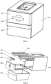
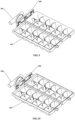
FIG. 1 is a schematic structural diagram of an ice-making device according to an embodiment of the present application; -
FIG. 2 is a schematic exploded view of an ice-making device according to an embodiment of the present application; -
FIG. 3 is a schematic structural diagram of a bracket according to an embodiment of the present application; -
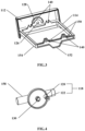
FIG. 4 is a schematic structural diagram of an operating member according to an embodiment of the present application; -
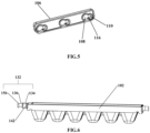
FIG. 5 is a schematic structural diagram of a connector according to an embodiment of the present application; -
FIG. 6 is a schematic structural diagram of an ice-making box according to an embodiment of the present application; -
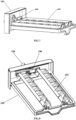
FIG. 7 is a schematic structural diagram of a bracket mounted with an ice-making box and an operating member in a bracket according to an embodiment of the present application; -
FIG. 8 is a schematic structural diagram of an ice-making box in a de-icing state according to an embodiment of the present application; -
FIG. 9 is a schematic structural diagram in which an operating member and an ice-making box are located in a plurality of releasing holes according to an embodiment of the present application; -
FIG. 10 is a schematic structural diagram in which an operating member and an ice-making box are located in a plurality of limiting holes according to an embodiment of the present application; -
FIG. 11 is a schematic top view in which an operating member and an ice-making box are located in a plurality of limiting holes according to an embodiment of the present application; and -
FIG. 12 is a schematic sectional view of an A-A direction inFIG. 11 . - 100: bracket; 102: ice-making box; 104: operating member; 106: connector; 108: releasing hole; 110: limiting hole; 112: panel; 114: frame; 116: transition section; 118: first connecting column; 120: first connecting section; 122: first limiting section; 124: first transition surface; 126: through hole; 128: guide groove; 130: connecting head; 132: second connecting column; 134: second connecting section; 136: second limiting section; 138: second transition surface; 140: assembly hole; 142: installation column; 144: ice storage box; 146: housing; 148: torsion spring; 150: stopper bar; 152: supporting structure; 154: limiting protrusion; 156: limiting boss; 158: handle structure.
- The implementation of the present application is further described in detail below in combination with the accompanying drawings and embodiments. The following embodiments are used to describe the present application, but cannot be used to limit the scope of the present application.
- In the description of the present application, it is to be noted that, the orientation or positional relations specified by terms such as "central", "longitudinal", "transverse", "upper", "lower", "front", "back", "left", "right", "vertical", "horizontal", "top", "bottom", "inner", "outer" and the like, are based on the orientation or positional relations shown in the drawings, which is merely for convenience of description of the present application and to simplify description, but does not indicate or imply that the stated devices or components must have the particular orientation and be constructed and operated in a particular orientation, and thus it is not to be construed as limiting the present application. Furthermore, the terms "first", "second", "third" and the like are only used for descriptive purposes and should not be construed as indicating or implying a relative importance.
- In the description of the present application, it is to be noted that unless explicitly specified and defined otherwise, the terms "connected to" and "connected" shall be understood broadly, for example, it may be either fixedly connected or detachably connected, or can be integrated; it may be either mechanically connected, or electrically connected; it may be either directly connected, or indirectly connected through an intermediate medium. The specific meanings of the terms above in the present application can be understood by a person skilled in the art in accordance with specific conditions.
- In the embodiments of the present application, unless otherwise expressly specified and defined, a first feature is "on" or "under" a second feature can refer to that the first feature is directly contacted with the second feature, or the first feature is indirectly contacted with the second feature through an intermediate medium. And further, the first feature is "on", "above" and "over" the second feature can refer to that the first feature is directly above or obliquely above the second feature, or simply refer to that the level height of the first feature is higher than level height of the second feature. The first feature is "under", "below" and "beneath" the second feature can refer to that the first feature is directly below or obliquely below the second feature, or simply refer to that the level height of the first feature is lower than level height of the second feature.
- In the description of this specification, description with reference to the terms "one embodiment", "some embodiments", "an example", "specific example", "some examples" and the like, refers to that specific features, structures, materials or characteristics described in combination with an embodiment or an example are included in at least one embodiment or example according to the embodiments of the present application. In this specification, schematic representations of the above terms are not necessarily directed to a same embodiment or example. Furthermore, the particular features, structures, materials or characteristics described can be combined in any suitable manner in any one or more embodiments or examples. In addition, those skilled in the art may combine the different embodiments or examples described in this specification, as well as the features of the different embodiments or examples, without conflicting each other.
- As shown in
FIG. 1 to FIG. 12 , an embodiment of the present application provides an ice-making device, including abracket 100, an operatingmember 104 and aconnector 106; where thebracket 100 is provided with a plurality of ice-makingboxes 102; the operatingmember 104 is mounted on thebracket 100; and theconnector 106 is connected between the operatingmember 104 and the plurality of ice-makingboxes 102 and thus the operatingmember 104 drives the plurality of ice-makingboxes 102 to act; where theconnector 106 is provided with a plurality of releasingholes 108 and limitingholes 110 being in one-to-one correspondence with the operatingmember 104 and the plurality of ice-makingboxes 102 and communicating with each other; theconnector 106 is switched between a releasing position at which the operatingmember 104 and the plurality of ice-makingboxes 102 are respectively connected to the releasingholes 108 and are disassembled from the releasingholes 108, and a limiting position at which the operatingmember 104 and the plurality of ice-makingboxes 102 are respectively connected to the limitingholes 110. - In the ice-making device provided by the embodiments of the present application, the operating
member 104 and the plurality of ice-makingboxes 102 are connected by using aconnector 106, while a plurality of releasingholes 108 and limitingholes 110 communicating with each other are arranged on theconnector 106, and theconnector 106 can be switched between the releasing position and the limiting position. When theconnector 106 is at the releasing position, the operatingmember 104 and the plurality of ice-makingboxes 102 are connected to the releasingholes 108 and can act axially relative to the releasingholes 108 to release from the releasingholes 108, and thus the operatingmember 104 and the plurality of ice-makingboxes 102 can be disassembled along the axial direction of the releasingholes 108. When theconnector 106 is at the limiting position, the operatingmember 104 and the plurality of ice-makingboxes 102 are connected to the limitingholes 110, and thus theconnector 106 can be axially limited, and thus the operatingmember 104 and the plurality of ice-makingboxes 102 can be mounted in a linkage manner. In this way, the user only needs to adjust the position of theconnector 106 to disassemble and assemble the operatingmember 104 and the plurality of ice-makingboxes 102, which improves the disassembly and assembly efficiency of the ice-makingboxes 102 and is convenient for the user to clean the plurality of ice-makingboxes 102. In addition, by connecting the plurality of ice-makingboxes 102 to the operatingmember 104 through theconnector 106, the user can invert the plurality of ice-makingboxes 102 only by rotating the operatingmember 104, the steps of de-icing for each ice-makingbox 102 separately in the related art are eliminated, and the de-icing efficiency of the plurality of ice-makingboxes 102 is improved. - In an embodiment of the present application, the operating
member 104 and the plurality of ice-makingboxes 102 are mounted on thebracket 100 by using theconnector 106, while a plurality of releasingholes 108 and limitingholes 110 communicating with each other are arranged on theconnector 106, and theconnector 106 can be switched between the releasing position and the limiting position. When theconnector 106 is at the releasing position, the operatingmember 104 and the plurality of ice-makingboxes 102 are connected to the releasingholes 108 and can act axially relative to the releasingholes 108 to release from the releasingholes 108, and thus the operatingmember 104 and the plurality of ice-makingboxes 102 can be disassembled along the axial direction of the releasingholes 108. When theconnector 106 is at the limiting position, the operatingmember 104 and the ice-makingboxes 102 are connected to the limitingholes 110, and thus the operatingmember 104 and the ice-makingboxes 102 can be mounted in a linkage manner. In this way, the user only needs to adjust the position of theconnector 106 to disassemble and assemble the operatingmember 104 and the ice-makingboxes 102, which improves the disassembly and assembly efficiency of the ice-makingboxes 102 and is convenient for the user to clean the ice-makingboxes 102. In addition, the number of ice-makingboxes 102 is plurality, and the plurality of ice-makingboxes 102 can be connected to theconnector 106. In this case, the plurality of ice-makingboxes 102 can be inverted only by theconnector 106, and thus de-icing is performed efficiently. - The ice-making device according to the present application mainly includes a
bracket 100, an operatingmember 104 and aconnector 106. Thebracket 100 is used to support the ice-makingboxes 102 and mount the operatingmember 104. The operatingmember 104 is used to facilitate the user to swivel and de-ice the ice-makingboxes 102. Theconnector 106 is used to connect the operatingmember 104 and the plurality of ice-makingboxes 102 and thus the operatingmember 104 can simultaneously drive the plurality of ice-makingboxes 102 for de-icing. - In an embodiment of the present application, as shown in
FIG. 3 , thebracket 100 includes apanel 112 and aframe 114 connected to thepanel 112, where theframe 114 is roughly a rectangular and mounted on a side of thepanel 112. The operatingmember 104 is rotatably connected to thepanel 112, the number of the ice-makingboxes 102 is plurality, and the plurality of ice-makingboxes 102 are rotatably connected to theframe 114. - As shown in
FIG. 3 , thepanel 112 is provided with a throughhole 126, and the operatingmember 104 is provided with a connectinghead 130 in rotation-match with the throughhole 126. An end of the connectinghead 130 on the operatingmember 104 is provided with one or more claws. When the connectinghead 130 is inserted into the throughhole 126, the claws at the end of the connectinghead 130 can be clamped to an outer end surface of the throughhole 126 on thepanel 112, thereby realizing the rotation connection between the operatingmember 104 and thepanel 112. - As mentioned above, in order to facilitate de-icing, the plurality of ice-making
boxes 102 can swivel relative to theframe 114. For example, the number of the ice-makingboxes 102 is two and the two ice-makingboxes 102 are arranged side by side on theframe 114 and can swivel relative to theframe 114. In order to mount the ice-makingboxes 102, two opposite ends of theframe 114 are provided withassembly holes 140 used for mounting the ice-makingboxes 102. As shown inFIG. 3 , the assembly holes 140 can be provided at an end of theframe 114 proximal to thepanel 112 and an end of theframe 114 away from thepanel 112. In addition, in order to conveniently mount the ice-makingboxes 102 on theframe 114 or detach it from theframe 114, theassembly hole 140 on the end of theframe 114 proximal to thepanel 112 is anassembly hole 140 with an opening, and theassembly hole 140 on the end of theframe 114 away from thepanel 112 is a fully closedassembly hole 140. Correspondingly, two opposite ends of the ice-makingboxes 102 are provided withinstallation columns 142 used for installing in theassembly hole 140. - When it is needed to mount the ice-making
boxes 102 on theframe 114, theinstallation column 142 at an end of the ice-makingboxes 102 can be inserted into the fully closedassembly hole 140, and then theinstallation column 142 at another end of the ice-makingboxes 102 can be inserted into theassembly hole 140 with an opening. In this way, the convenience of mounting the ice-makingboxes 102 on theframe 114 can be improved, and the deformation of the ice-makingboxes 102 can be reduced, and the fully closedassembly hole 140 can effectively prevent theinstallation column 142 from falling out. - When it is needed to detach the ice-making
boxes 102 from theframe 114, theinstallation column 142 located in theassembly hole 140 with an opening can be taken out first, and then theinstallation column 142 in the fully closedassembly hole 140 can be taken out. - In order to limit the position of the ice-making
boxes 102 on theframe 114, an end of theinstallation column 142 is provided with a limitingboss 156. An axial action of the ice-makingboxes 102 relative to theassembly hole 140 can be limited by abutting the limitingboss 156 against an end surface of theassembly hole 140 with an opening. - In other embodiments, all assembly holes 140 can be set as fully closed assembly holes 140, or all assembly holes 140 can be set as assembly holes 140 with opening.
- When the ice-making
boxes 102 needs to be de-iced, in order to limit the swivel of the ice-makingboxes 102, an end of theframe 114 away from thepanel 112 is provided withstopper bars 150, and for example, the stopper bars 150 can be provided on an inner wall of theframe 114. In this case, when the ice-makingboxes 102 swivels, the outer wall of the ice trays on the ice-makingboxes 102 can abut against thestopper bar 150 to limit the swivel angle of the ice-makingboxes 102. It should be noted that the number of the stopper bars 150 corresponds to the number of the ice-makingboxes 102. After the stopper bars 150 abut against the outer wall of the ice trays of the ice-makingboxes 102, the user continues to swivel the operatingmember 104, and thus the ice-makingboxes 102 continues to twist to make the ice in each ice tray of the ice-makingboxes 102 fall off. Therefore, the ice-makingboxes 102 can be made of materials with certain deformation, such as polypropylene, acrylonitrile, butadiene, styrene three monomers of terpolymer or engineering plastics, etc. - In addition, in order to automatically reset the ice-making
boxes 102, that is, to switch the ice-makingboxes 102 from the de-icing state to the ice-making state, theinstallation column 142 of each ice-makingbox 102 is sleeved with a reset member. The reset member can be atorsion spring 148, where an end of thetorsion spring 148 abuts tightly against the ice-makingbox 102, and another end of thetorsion spring 148 abuts tightly against theframe 114. For example, an end of thetorsion spring 148 can abut tightly against the bottom of the ice-makingbox 102, and the another end of thetorsion spring 148 can abut tightly against thestopper bar 150. It should be noted here that in order to abut tightly the another end of thetorsion spring 148, twostopper bars 150 can be arranged along the height direction of theframe 114, and the another end of thetorsion spring 148 can be bent to form a bending section capable of being inserted a gap between the two stopper bars 150. In this case, when the user swivels the operatingmember 104, the operatingmember 104 can drive the ice-makingboxes 102 to be switched from the ice-making state to the de-icing state through theconnector 106. After the de-icing operation is completed, the ice-makingboxes 102 can be switched from the de-icing state to the ice-making state under the elastic restoring force of thetorsion spring 148. - In other embodiments, the
torsion spring 148 is not essential and the ice-makingboxes 102 can be de-iced and reset only by the user swivels the operatingmember 104. - The bottom of one end of the
frame 114 away from thepanel 112 is provided with a supportingstructure 152, where the bottom of the supportingstructure 152 is flush with the bottom of thepanel 112. In this case, when the user removes thebracket 100 and pours water to the ice-makingboxes 102, thebracket 100 can be stably placed on a table through being supported by the bottom of thepanel 112 and the bottom of the supportingstructure 152 to prevent water overflow. - In other embodiments, when it is needed to pour water to the ice-making
boxes 102, water can be injected into the ice-makingbox 102 through the water injection hole at the top of thehousing 146, which saves the step of taking out the ice-makingbox 102 and improves the ice-making efficiency. - Referring to
FIG. 1 and FIG. 2 , according to an embodiment of the present application, the ice-making device further includesice storage box 144 arranged below thebracket 100 and corresponding to the ice-makingboxes 102. - The
ice storage box 144 and thebracket 100 are independent to each other, and thus the user can take out theice storage box 144 separately. When the ice-makingbox 102 is de-iced, the ice made in the ice-makingbox 102 can directly fall into theice storage box 144 with the swivel of the ice-makingbox 102. In addition, in order to facilitate the user's observation to the quantity of ice in theice storage box 144, theice storage box 144 can be made of transparent materials. In addition, a pulling slot can be provided on theice storage box 144 to facilitate the user to pull out theice storage box 144. - Referring to
FIG. 1 and FIG. 2 , according to an embodiment of the present application, the ice-making device further includes ahousing 146, where thebracket 100 and theice storage box 144 are movablely arranged in thehousing 146. - By providing the
housing 146 and arranging thebracket 100 and theice storage box 144 in thehousing 146, it is convenient for users to carry them. In order to pull out and push back thebracket 100 and theice storage box 144 conveniently, a corresponding slide rail or chute can be provided inside thehousing 146. An edge of thebracket 100 and an edge of theice storage box 144 can be directly arranged on the slide rail or inserted in the chute, which can reduce the resistance of thebracket 100 and theice storage box 144 during the pull-out and push-back process and improve the user's convenience. - It should be noted here that in most situations, it is unnecessary to completely detach the
bracket 100 from thehousing 146. Therefore, in order to avoid complete removal of thebracket 100 from thehousing 146, referring toFIG. 3 , the bottom of theframe 114 can be provided with a limitingprotrusion 154, which can ensure that theframe 114 is not easy to slip from thehousing 146 when the ice-making device is tilted. Further, by arranging the limitingprotrusion 154 at the bottom of theframe 114, it is also possible to reduce the friction between theframe 114 and the slide rail or chute in thehousing 146, and facilitate the user to pull theframe 114. - In an embodiment of the present application, the operating
member 104 and the ice-makingbox 102 is connected by relying on theconnector 106. That is, theconnector 106 is arranged between the operatingmember 104 and the ice-makingbox 102, and the operatingmember 104 and the ice-makingbox 102 can be assembled and disassembled through the cooperation of theconnector 106 and thebracket 100. - A plurality of releasing
holes 108 and limitingholes 110 communicating with each other are arranged on theconnector 106. It should be noted that both the operatingmember 104 and the ice-makingboxes 102 are connected to theconnector 106. Therefore, the numbers of releasingholes 108 and the limitingholes 110 on theconnector 106 correspond to the number of the operatingmembers 104 and the ice-makingboxes 102. For example, the number of the ice-makingboxes 102 is two, the number of the operatingmember 104 is one, and the number of the corresponding releasingholes 108 and the limitingholes 110 are three, respectively. - In an embodiment the present application, the
connector 106 can be switched between the releasing position and the limiting position. When theconnector 106 is at the releasing position, the operatingmember 104 and the ice-makingboxes 102 are respectively installed in the corresponding releasingholes 108 on theconnector 106, and both the operatingmember 104 and the ice-makingboxes 102 can be disassembled from thebracket 100. When theconnector 106 is at the limiting position, the operatingmember 104 and the ice-makingboxes 102 are installed in the corresponding limitingholes 110 on theconnector 106, the axial movement of theconnector 106 is limited, and the operatingmember 104 and the ice-makingboxes 102 are mounted on thebracket 100. - The function of the
connector 106 is described below in combination with a specific structure of theconnector 106. - Referring to
FIG. 5 andFIG. 12 , in an embodiment of the present application, the aperture of the releasinghole 108 on theconnector 106 is larger than the aperture of the limitinghole 110 on theconnector 106, and atransition section 116 is formed between the releasinghole 108 and the limitinghole 110. The aperture of thetransition section 116 is smaller than the aperture of the limitinghole 110. - In an embodiment, the releasing
hole 108 and the limitinghole 110 on theconnector 106 can form a structure similar to a gourd hole. The aperture of the releasinghole 108 is larger than the aperture of the limitinghole 110, and atransition section 116 is arranged between the releasinghole 108 and the limitinghole 110 to form the transition between the releasinghole 108 and the limitinghole 110. Since the releasinghole 108 and the limitinghole 110 communicate with each other, thetransition section 116 has a certain aperture, and the aperture of thetransition section 116 is smaller than the aperture of the limitinghole 110. Thus, when the operatingmember 104 and the ice-makingbox 102 are installed in the releasinghole 108, both the operatingmember 104 and the ice-makingbox 102 are able to move in the axial direction of the releasinghole 108 relative to theconnector 106 so that the user can detach the operatingmember 104 and the ice-makingbox 102 from thebracket 100. When the operatingmember 104 and the ice-makingbox 102 are installed in the limitinghole 110, the operatingmember 104 and the ice-makingbox 102 can be limited by the limitinghole 110, and thus the operatingmember 104 and the ice-makingbox 102 are limited in the limitinghole 110. - Referring to
FIG. 4 , in order to achieve the above purpose, the operatingmember 104 is provided with a first connectingcolumn 118. The first connectingcolumn 118 includes a first connectingsection 120 and a first limitingsection 122. The diameter of the first connectingsection 120 is matched with the aperture of the releasinghole 108, and the diameter of the first limitingsection 122 is matched with the aperture of the limitinghole 110. - In an embodiment, the first connecting
column 118 for connecting theconnector 106 is arranged at the side of the operatingmember 104 with the connectinghead 130. The first connectingcolumn 118 is not a complete cylindrical section structure. The root of the first connectingcolumn 118 is a complete cylindrical section, which is part of the first connectingsection 120. The diameter of thefirst connection section 120 is equal to or slightly less than the aperture of the releasinghole 108, but it is necessary to ensure that the diameter of thefirst connection section 120 is greater than the aperture of the limitinghole 110. A cylindrical section with a slightly smaller diameter is arranged upward from the first connectingsection 120, which is the first limitingsection 122, and the diameter of the first limitingsection 122 is equal to or slightly less than the aperture of the limitinghole 110. A complete cylindrical section is arranged upward from the first limitingsection 122, which is another part of the first connectingsection 120. - In this case, when the
connector 106 is at the releasing position, the first connectingcolumn 118 on the operatingmember 104 is aligned with the releasinghole 108 on theconnector 106. Since the diameter of the first connectingsection 120 on the first connectingcolumn 118 is equal to or slightly smaller than the aperture of the releasinghole 108, the operatingmember 104 can move along the axial direction of the releasinghole 108 and the user can detach the operatingmember 104 from thepanel 112 only by taking out the operatingmember 104 along the axial direction of the releasinghole 108. When theconnector 106 is at the limiting position, since the operatingmember 104 is fixed by thepanel 112 on thebracket 100, the position of the first connectingcolumn 118 is fixed. By pushing theconnector 106, the first connectingcolumn 118 can slide into the limitinghole 110 from the releasinghole 108. Since both ends of the first limitingsection 122 are provided with the first connectingsection 120 having a diameter greater than the aperture of the limitinghole 110, the axial movement of the first connectingcolumn 118 relative to the limitinghole 110 is limited, thereby limiting the axial movement of theconnector 106. - Referring to
FIG. 12 , as mentioned above, since atransition section 116 is arranged between the releasinghole 108 and the limitinghole 110 and the aperture of thetransition section 116 is smaller than the aperture of the limitinghole 110, in order to ensure that the first connectingcolumn 118 can smoothly slide from the releasinghole 108 into the limitinghole 110, the first limitingsection 122 is provided with afirst transition surface 124 used for passing the first limitingsection 122 through thetransition section 116. - The
first transition surface 124 mentioned here can be any one of the plane and wavy surfaces. The maximum size between thefirst transition surface 124 and the outer side of the first limitingsection 122 is larger than the aperture of thetransition section 116. In an embodiment, the first limitingsection 122 is clipped into the limitinghole 110 after passing through thetransition section 116 by means of interference fit, which can prevent the first limitingsection 122 from sliding out of the limitinghole 110. - It should be noted that in order to prevent the first connecting
column 118 from disengaging from the limitinghole 110 during the de-icing process, thefirst transition surface 124 needs to be swiveled in a direction away from thetransition section 116. As shown inFIG. 12 , for example, the first connectingcolumn 118 swivels counterclockwise to de-ice, and correspondingly, thefirst transition surface 124 is arranged in the downward direction on the first limitingsection 122. If the first connectingcolumn 118 swivels clockwise to de-ice, thefirst transition surface 124 should be arranged in the upward direction on the first limitingsection 122. In this case, when the first connectingcolumn 118 swivels, thefirst transition surface 124 swivels away from thetransition section 116, so that the first connectingcolumn 118 can be prevented from disengaging from the limitinghole 110. - Referring to
FIG. 3 , according to an embodiment of the present application, thepanel 112 is provided with aguide groove 128, and the first connectingcolumn 118 is adapted to pass through theguide groove 128 to be connected to theconnector 106. - Since the swivel path of the first connecting
column 118 is arc when the first connectingcolumn 118 swivels, theguide groove 128 is an arc groove. By arranging theguide groove 128, it can provide guidance for the swivel of the first connectingcolumn 118, which ensures the stability when the user turns the operatingmember 104. Further, by arranging theguide groove 128, when the user turns the operatingmember 104, the operatingmember 104 can take theconnection head 130 as the center of a circle and the distance between the first connectingcolumn 118 and theconnection head 130 as the radius, to make that through the guidance of theguide groove 128, the user is more labor-saving for turning the operatingmember 104, and then the inversion operation of the ice-makingbox 102 can be completed to rapidly and effortlessly de-ice. - It should be noted that during the user turns the operating
member 104, the operatingmember 104 only swivels with theconnection head 130 as the center of the circle, while the first connectingcolumn 118 swivels eccentrically with the swivel of the operatingmember 104 relative to theconnection head 130. Due to the guiding effect of theguide groove 128 on the first connectingcolumn 118, the motion path of the first connectingcolumn 118 is limited, thereby achieving the labor-saving operation of de-icing. - Referring to
FIG. 4 , in an embodiment of the present application, in order to facilitate the user to hold, the operatingmember 104 is provided with ahandle structure 158. In actual operation, the user can hold thehandle structure 158 to apply greater torque to the ice-makingbox 102, thereby making the de-icing smoother. - Referring to
FIG. 6 , in order to disassemble and assemble the ice-makingbox 102 through theconnector 106, an end of the ice-makingbox 102 facing thepanel 112 is provided with a second connectingcolumn 132. The second connectingcolumn 132 includes a second connectingsection 134 and a second limitingsection 136. The diameter of the second connectingsection 134 is matched with the aperture of the releasinghole 108, and the diameter of the second limitingsection 136 is matched with the aperture of the limitinghole 110. - lin an embodiment, the second connecting
column 132 used for connecting theconnector 106 is arranged at an end of the ice-makingbox 102 facing thepanel 112 in thebracket 100. Similarly, the second connectingcolumn 132 is not a complete cylindrical section structure. The root of the second connectingcolumn 132 is a complete cylindrical section, which is part of the second connectingsection 134. The diameter of thesecond connection section 134 is equal to or slightly less than the aperture of the releasinghole 108, but it is necessary to ensure that the diameter of thesecond connection section 134 is greater than the aperture of the limitinghole 110. A cylindrical section with a slightly smaller diameter is arranged upward from the second connectingsection 134, which is the second limitingsection 136. The diameter of the second limitingsection 136 is equal to or slightly less than the aperture of the limitinghole 110. A complete cylindrical section is arranged upward from the second limitingsection 136, which is another part of the second connectingsection 134. That is, the structure of the second connectingcolumn 132 arranged on the ice-makingbox 102 is exactly the same as the structure of the first connectingcolumn 118 arranged on the operatingmember 104. - In this case, when the
connector 106 is at the releasing position, the second connectingcolumn 132 on the ice-makingbox 102 and the releasinghole 108 on theconnector 106 are aligned with each other. Since the diameter of the second connectingsection 134 on the second connectingcolumn 132 is equal to or slightly smaller than the aperture of the releasinghole 108, theconnector 106 can move along the axial direction of the releasinghole 108, and the user can detach the ice-makingbox 102 from thebracket 100 only by taking out theconnector 106 along the axial direction of the releasinghole 108. When theconnector 106 is at the limiting position, since the ice-makingbox 102 is fixed by theframe 114 on thebracket 100, the position of the second connectingcolumn 132 is fixed. By pushing theconnector 106, the second connectingcolumn 132 can slide from the releasinghole 108 into the limitinghole 110. Since both ends of the second limitingsection 136 are provided with the second connectingsection 134 having a diameter greater than the aperture of the limitinghole 110, the axial motion of the second connectingcolumn 132 relative to the limitinghole 110 is limited, which further limits the axial motion of theconnector 106, and thus theconnector 106, the operatingmember 104 and the ice-makingbox 102 are stably mounted. - Referring to
FIG. 12 , as mentioned above, since atransition section 116 is arranged between the releasinghole 108 and the limitinghole 110 and the aperture of thetransition section 116 is smaller than the aperture of the limitinghole 110, in order to ensure that the second connectingcolumn 132 can smoothly slide from the releasinghole 108 into the limitinghole 110, the second limitingsection 136 is provided with asecond transition surface 138 used for passing the second limitingsection 136 through thetransition section 116. - The
second transition surface 138 mentioned here can be any one of the plane and wave surfaces. The maximum size between thesecond transition surface 138 and the outer side of the second limitingsection 136 is larger than the aperture of thetransition section 116. In an embodiment, the second limitingsection 136 is clipped into the limitinghole 110 after passing through thetransition section 116 by interference fit, which can prevent the second limitingsection 136 from sliding out of the limitinghole 110. - It should be noted that in order to prevent the second connecting
column 132 from disengaging from the limitinghole 110 during the de-icing process, thesecond transition surface 138 needs to be swiveled in a direction away from thetransition section 116. As shown inFIG. 12 , for example, the second connectingcolumn 132 swivels counterclockwise to de-ice, and correspondingly, thesecond transition surface 138 is arranged in the downward direction on the second limitingsection 136. If the second connectingcolumn 132 swivels clockwise to de-ice, thesecond transition surface 138 should be arranged in upward direction on the second limitingsection 136. In this case, when the second connectingcolumn 132 swivels, thesecond transition surface 138 swivels away from thetransition section 116, and thus the second connectingcolumn 132 can be prevented from disengaging from the limitinghole 110. - The method for mounting the ice-making device provided by the embodiments of the present application is briefly described below.
- The operating
member 104 is clipped into the throughhole 126 on thepanel 112 through the connectinghead 130, and the first connectingcolumn 118 on the operatingmember 104 passes through theguide groove 128 on thepanel 112 and is then inserted into the releasinghole 108 on theconnector 106. The second connectingcolumn 132 on the ice-makingbox 102 at the back end (an end away from the connector 106) is inserted into theclosed assembly hole 140, and then the second connectingcolumn 132 on the ice-makingbox 102 at the front end (an end proximal to the connector 106) is inserted into theopen assembly hole 140. In addition, the second connectingcolumn 132 located at the front end of the ice-makingbox 102 is inserted into the releasinghole 108 on both sides of theconnector 106, and then sliding theconnector 106 in a side direction so that the first limitingsection 122 of the first connectingcolumn 118 and the second limitingsection 136 of the second connectingcolumn 132 are respectively clipped into the limitingholes 110 corresponding to theconnector 106 by interference fit to complete the assembly. Then by turning the operatingmember 104, the two ice-makingboxes 102 can be inverted through the leading of theconnector 106 to complete the de-icing operation. - The disassembly and assembly method of the ice-making device according to the embodiments of the present application is briefly described below.
- By sliding the
connector 106 reversely, the first limitingsection 122 of the first connectingcolumn 118 and the second limitingsection 136 of the second connectingcolumn 132 slide into the corresponding releasingholes 108 on theconnector 106, respectively. At this time, the operatingmember 104 can be disassembled from thepanel 112 along the axial direction of theconnector 130, and the ice-makingbox 102 can be disassembled along the axial direction of the second connectingcolumn 132, while theconnector 106 can also be removed. - An embodiment of the present application provides a refrigeration machine, including a cabinet body and the ice-making device mentioned above, where the ice-making device is arranged in the cabinet body.
- According to the refrigeration machine provided by the embodiments of the present application, the de-icing efficiency of the ice-making
box 102 can be improved by arranging the ice-making device mentioned above in the cabinet body, and it is convenient for the user to assemble and disassemble the ice-makingbox 102 to facilitate the user to clean the ice-makingbox 102. - The refrigeration machine provided by the present application can be a refrigerator, a freezer and other refrigeration machine involving ice making and ice storage.
- Finally, it should be noted that the above embodiments are only used to illustrate the solutions of the present application, rather than limiting the solutions. Although the present application is described in detail with reference to the above embodiments, those of ordinary skill in the art should understand that: they can still modify the solutions recorded in the above embodiments, or make equivalent replacements to some of the features; these modifications or replacements do not make the essence of the corresponding solutions depart from the scope of the solutions of various embodiments of the present application.
- The above embodiments are only used to illustrate the solutions of the present application, rather than limiting the solutions. Although the present application is described in detail with reference to the above embodiments, those of ordinary skill in the art should understand that the various combinations, modifications or equivalent replacements of the solutions of the present application are not divorced from the scope of the solutions of the present application, and should be covered in the scope of the claims of the present application.
Claims (14)
- An ice-making device, comprising:a bracket (100), provided with a plurality of ice-making boxes (102);an operating member (104), mounted on the bracket (100); anda connector (106), connected between the operating member (104) and the plurality of ice-making boxes (102) to enable the operating member (104) to drive the plurality of ice-making boxes (102) to act; wherein the connector (106) is provided with a plurality of releasing holes (108) and limiting holes (110) being in one-to-one correspondence with the operating member (104) and the plurality of ice-making boxes (102) and communicating with each other; the connector (106) is switched between a releasing position at which the operating member (104) and the plurality of ice-making boxes (102) are respectively connected to the releasing holes (108) and are disassembled from the releasing holes (108), and a limiting position at which the operating member (104) and the plurality of ice-making boxes (102) are respectively connected to the limiting holes (110).
- The ice-making device of claim 1, wherein the bracket (100) comprises a panel (112) and a frame (114) connected to the panel (112), the operating member (104) is rotatably connected to the panel (112), and the plurality of ice-making boxes (102) are rotatably connected to the frame (114).
- The ice-making device of claim 2, wherein an aperture of each of the releasing holes (108) is larger than an aperture of each of the limiting holes (110), and a transition section (116) is provided between each of the releasing holes (108) and each of the limiting holes (110), and an aperture at the transition section (116) is smaller than the aperture of the limiting hole (110).
- The ice-making device of claim 3, wherein each ice-making box (102) is provided with a second connecting column (132) which comprises a second connecting section (134) and a second limiting section (136); where a diameter of the second connecting section (134) is matched with the aperture of the releasing hole (108), and a diameter of the second limiting section (136) is matched with the aperture of the limiting hole (110).
- The ice-making device of claim 4, wherein the second limiting section (136) is provided with a second transition surface (138) for passing the second limiting section (136) through the transition section (116).
- The ice-making device of claim 4, wherein two opposite ends of the frame (114) are provided with assembly holes (140) configured to mount the plurality of ice-making boxes (102), and the plurality of ice-making boxes (102) are provided with installation columns (142) configured to be installed in the plurality of assembly holes (140).
- The ice-making device of claim 6, wherein the frame (114) is provided with a stopper bar (150), and the stopper bar (150) abuts against ice trays of the plurality of ice-making boxes (102) to limit a swivel angle of the plurality of ice-making boxes (102) relative to the frame (114).
- The ice-making device of claim 6, wherein each installation column (142) is sleeved with a reset member configured to switch the plurality of ice-making boxes (102) from a de-icing state to an ice-making state, and two ends of the reset member abut against the plurality of ice-making boxes (102) and the frame (114), respectively.
- The ice-making device of any one of claims 3 to 8, wherein the operating member (104) is provided with a first connecting column (118) comprising a first connecting section (120) and a first limiting section (122), wherein a diameter of the first connecting section (120) is matched with the aperture of the releasing hole (108), and a diameter of the first limiting section (122) is matched with the aperture of the limiting hole (110).
- The ice-making device of claim 9, wherein the first limiting section (122) is provided with a first transition surface (124) for passing the first limiting section (122) through the transition section (116).
- The ice-making device of claim 9, wherein the panel (112) is provided with a through hole (126) and a guide groove (128), wherein the operating member (104) is provided with a connecting head (130) in rotation-match with the through hole (126), and the first connecting column (118) is adapted to pass through the guide groove (128) to connect to the connector (106).
- The ice-making device of any one of claims 1 to 8, further comprising an ice storage box (144) arranged below the bracket (100) and corresponding to the plurality of ice-making boxes (102).
- The ice-making device of claim 12, further comprising a housing (146), wherein the bracket (100) and the ice storage box (144) are movablely mounted on the housing (146).
- A refrigeration machine, comprising a cabinet body and an ice-making device of any one of claims 1 to 13, wherein the ice-making device is arranged in the cabinet body.
Applications Claiming Priority (3)
| Application Number | Priority Date | Filing Date | Title |
|---|---|---|---|
| CN202111408552.2A CN115451630B (en) | 2021-11-19 | 2021-11-19 | Ice making device and refrigeration equipment |
| CN202111408553.7A CN115406145B (en) | 2021-11-19 | 2021-11-19 | Ice making devices and refrigeration equipment |
| PCT/CN2021/143767 WO2023087513A1 (en) | 2021-11-19 | 2021-12-31 | Ice-making device and refrigeration apparatus |
Publications (3)
| Publication Number | Publication Date |
|---|---|
| EP4206577A1 true EP4206577A1 (en) | 2023-07-05 |
| EP4206577A4 EP4206577A4 (en) | 2023-11-29 |
| EP4206577B1 EP4206577B1 (en) | 2025-07-02 |
Family
ID=84901719
Family Applications (1)
| Application Number | Title | Priority Date | Filing Date |
|---|---|---|---|
| EP21939587.8A Active EP4206577B1 (en) | 2021-11-19 | 2021-12-31 | Ice-making device and refrigeration apparatus |
Country Status (4)
| Country | Link |
|---|---|
| US (1) | US12259168B2 (en) |
| EP (1) | EP4206577B1 (en) |
| ES (1) | ES3040316T3 (en) |
| WO (1) | WO2023087513A1 (en) |
Family Cites Families (12)
| Publication number | Priority date | Publication date | Assignee | Title |
|---|---|---|---|---|
| JP2000220927A (en) | 1999-01-28 | 2000-08-08 | Sanyo Electric Co Ltd | Automatic ice plant |
| JP2000346509A (en) | 1999-06-02 | 2000-12-15 | Sanyo Electric Co Ltd | Automatic ice-making device |
| JP2000346506A (en) | 1999-06-03 | 2000-12-15 | Sanyo Electric Co Ltd | Automatic icemaker |
| KR101275565B1 (en) | 2006-09-11 | 2013-06-14 | 엘지전자 주식회사 | Ice-making device for refrigerator |
| WO2012149691A1 (en) * | 2011-05-05 | 2012-11-08 | 合肥美的荣事达电冰箱有限公司 | Manual ice maker and refrigerator with the same |
| CN102305507B (en) | 2011-06-08 | 2013-05-22 | 合肥美的荣事达电冰箱有限公司 | Automatic ice maker and refrigerator with the same |
| CN102353195B (en) | 2011-07-27 | 2016-06-08 | 海尔集团公司 | A kind of ice making device of refrigerator |
| CN102788464B (en) | 2012-07-26 | 2014-09-03 | 海信容声(广东)冰箱有限公司 | Ice making device |
| CN103712390A (en) | 2013-12-30 | 2014-04-09 | 合肥晶弘电器有限公司 | Ice maker assembly and refrigerator adopting same |
| CN104748468B (en) | 2013-12-31 | 2017-02-15 | 苏州三星电子有限公司 | Rotary ice making box |
| CN109579407B (en) | 2018-11-28 | 2020-11-17 | 海信容声(广东)冰箱有限公司 | A kind of refrigerator |
| CN111174488A (en) | 2020-03-09 | 2020-05-19 | 合肥华凌股份有限公司 | Ice maker and refrigerator having the same |
-
2021
- 2021-12-31 ES ES21939587T patent/ES3040316T3/en active Active
- 2021-12-31 US US18/008,439 patent/US12259168B2/en active Active
- 2021-12-31 WO PCT/CN2021/143767 patent/WO2023087513A1/en not_active Ceased
- 2021-12-31 EP EP21939587.8A patent/EP4206577B1/en active Active
Also Published As
| Publication number | Publication date |
|---|---|
| WO2023087513A1 (en) | 2023-05-25 |
| US12259168B2 (en) | 2025-03-25 |
| EP4206577A4 (en) | 2023-11-29 |
| EP4206577B1 (en) | 2025-07-02 |
| US20240310102A1 (en) | 2024-09-19 |
| ES3040316T3 (en) | 2025-10-30 |
Similar Documents
| Publication | Publication Date | Title |
|---|---|---|
| EP3690362B1 (en) | Refrigerator | |
| US8215732B2 (en) | Vertically adjustable refrigerator shelf with hidden drive unit | |
| US10314393B2 (en) | Refrigerator appliance and variable shelf assembly | |
| EP3546866B1 (en) | Refrigerator | |
| EP2223026B1 (en) | Ice-making assembly of refrigerator | |
| US12259168B2 (en) | Ice-making device and refrigeration machine | |
| KR20060081921A (en) | Refrigerator | |
| CN111981739B (en) | Ice maker and refrigerator with same | |
| EP3967954B1 (en) | Ice maker and refrigerator | |
| CN108426401A (en) | Refrigerator | |
| CN115406145B (en) | Ice making devices and refrigeration equipment | |
| CN115451630B (en) | Ice making device and refrigeration equipment | |
| CN216432182U (en) | Ice maker and refrigerator | |
| CN115435520A (en) | Ice making device and refrigeration equipment | |
| EP3809067B1 (en) | A cooling device comprising an ice maker | |
| CN118670078A (en) | Shelving, refrigerators and storage | |
| KR200232034Y1 (en) | Refrigerator Ice Maker | |
| CN222504463U (en) | Ice maker and refrigeration equipment having the same | |
| US20250325141A1 (en) | Air heating cooker | |
| CN217760576U (en) | Door body opening and closing device and electric appliance | |
| CN108413694A (en) | Refrigerator | |
| CN121855133A (en) | Ice storage device with automatic ice discharging function | |
| CN112432406A (en) | Ice making device for refrigeration appliance and refrigeration appliance | |
| WO2025001212A1 (en) | Refrigerator | |
| CN119221785A (en) | Hinge and refrigeration equipment having the same |
Legal Events
| Date | Code | Title | Description |
|---|---|---|---|
| STAA | Information on the status of an ep patent application or granted ep patent |
Free format text: STATUS: UNKNOWN |
|
| STAA | Information on the status of an ep patent application or granted ep patent |
Free format text: STATUS: THE INTERNATIONAL PUBLICATION HAS BEEN MADE |
|
| PUAI | Public reference made under article 153(3) epc to a published international application that has entered the european phase |
Free format text: ORIGINAL CODE: 0009012 |
|
| STAA | Information on the status of an ep patent application or granted ep patent |
Free format text: STATUS: REQUEST FOR EXAMINATION WAS MADE |
|
| 17P | Request for examination filed |
Effective date: 20221109 |
|
| AK | Designated contracting states |
Kind code of ref document: A1 Designated state(s): AL AT BE BG CH CY CZ DE DK EE ES FI FR GB GR HR HU IE IS IT LI LT LU LV MC MK MT NL NO PL PT RO RS SE SI SK SM TR |
|
| A4 | Supplementary search report drawn up and despatched |
Effective date: 20231031 |
|
| RIC1 | Information provided on ipc code assigned before grant |
Ipc: F25C 1/10 20060101ALI20231025BHEP Ipc: F25D 11/02 20060101AFI20231025BHEP |
|
| DAV | Request for validation of the european patent (deleted) | ||
| DAX | Request for extension of the european patent (deleted) | ||
| GRAP | Despatch of communication of intention to grant a patent |
Free format text: ORIGINAL CODE: EPIDOSNIGR1 |
|
| STAA | Information on the status of an ep patent application or granted ep patent |
Free format text: STATUS: GRANT OF PATENT IS INTENDED |
|
| INTG | Intention to grant announced |
Effective date: 20250331 |
|
| GRAS | Grant fee paid |
Free format text: ORIGINAL CODE: EPIDOSNIGR3 |
|
| GRAA | (expected) grant |
Free format text: ORIGINAL CODE: 0009210 |
|
| STAA | Information on the status of an ep patent application or granted ep patent |
Free format text: STATUS: THE PATENT HAS BEEN GRANTED |
|
| AK | Designated contracting states |
Kind code of ref document: B1 Designated state(s): AL AT BE BG CH CY CZ DE DK EE ES FI FR GB GR HR HU IE IS IT LI LT LU LV MC MK MT NL NO PL PT RO RS SE SI SK SM TR |
|
| REG | Reference to a national code |
Ref country code: GB Ref legal event code: FG4D |
|
| REG | Reference to a national code |
Ref country code: CH Ref legal event code: EP |
|
| REG | Reference to a national code |
Ref country code: DE Ref legal event code: R096 Ref document number: 602021033607 Country of ref document: DE |
|
| REG | Reference to a national code |
Ref country code: IE Ref legal event code: FG4D |
|
| REG | Reference to a national code |
Ref country code: ES Ref legal event code: FG2A Ref document number: 3040316 Country of ref document: ES Kind code of ref document: T3 Effective date: 20251030 |
|
| REG | Reference to a national code |
Ref country code: NL Ref legal event code: MP Effective date: 20250702 |
|
| PG25 | Lapsed in a contracting state [announced via postgrant information from national office to epo] |
Ref country code: PT Free format text: LAPSE BECAUSE OF FAILURE TO SUBMIT A TRANSLATION OF THE DESCRIPTION OR TO PAY THE FEE WITHIN THE PRESCRIBED TIME-LIMIT Effective date: 20251103 |
|
| PG25 | Lapsed in a contracting state [announced via postgrant information from national office to epo] |
Ref country code: NL Free format text: LAPSE BECAUSE OF FAILURE TO SUBMIT A TRANSLATION OF THE DESCRIPTION OR TO PAY THE FEE WITHIN THE PRESCRIBED TIME-LIMIT Effective date: 20250702 |
|
| REG | Reference to a national code |
Ref country code: AT Ref legal event code: MK05 Ref document number: 1809627 Country of ref document: AT Kind code of ref document: T Effective date: 20250702 |
|
| PG25 | Lapsed in a contracting state [announced via postgrant information from national office to epo] |
Ref country code: IS Free format text: LAPSE BECAUSE OF FAILURE TO SUBMIT A TRANSLATION OF THE DESCRIPTION OR TO PAY THE FEE WITHIN THE PRESCRIBED TIME-LIMIT Effective date: 20251102 |
|
| PGFP | Annual fee paid to national office [announced via postgrant information from national office to epo] |
Ref country code: DE Payment date: 20251212 Year of fee payment: 5 |
|
| PG25 | Lapsed in a contracting state [announced via postgrant information from national office to epo] |
Ref country code: NO Free format text: LAPSE BECAUSE OF FAILURE TO SUBMIT A TRANSLATION OF THE DESCRIPTION OR TO PAY THE FEE WITHIN THE PRESCRIBED TIME-LIMIT Effective date: 20251002 |
|
| REG | Reference to a national code |
Ref country code: LT Ref legal event code: MG9D |
|
| PG25 | Lapsed in a contracting state [announced via postgrant information from national office to epo] |
Ref country code: AT Free format text: LAPSE BECAUSE OF FAILURE TO SUBMIT A TRANSLATION OF THE DESCRIPTION OR TO PAY THE FEE WITHIN THE PRESCRIBED TIME-LIMIT Effective date: 20250702 |
|
| PG25 | Lapsed in a contracting state [announced via postgrant information from national office to epo] |
Ref country code: FI Free format text: LAPSE BECAUSE OF FAILURE TO SUBMIT A TRANSLATION OF THE DESCRIPTION OR TO PAY THE FEE WITHIN THE PRESCRIBED TIME-LIMIT Effective date: 20250702 |
|
| PGFP | Annual fee paid to national office [announced via postgrant information from national office to epo] |
Ref country code: IT Payment date: 20251212 Year of fee payment: 5 |
|
| PG25 | Lapsed in a contracting state [announced via postgrant information from national office to epo] |
Ref country code: HR Free format text: LAPSE BECAUSE OF FAILURE TO SUBMIT A TRANSLATION OF THE DESCRIPTION OR TO PAY THE FEE WITHIN THE PRESCRIBED TIME-LIMIT Effective date: 20250702 |
|
| PG25 | Lapsed in a contracting state [announced via postgrant information from national office to epo] |
Ref country code: CZ Free format text: LAPSE BECAUSE OF FAILURE TO SUBMIT A TRANSLATION OF THE DESCRIPTION OR TO PAY THE FEE WITHIN THE PRESCRIBED TIME-LIMIT Effective date: 20250702 Ref country code: SE Free format text: LAPSE BECAUSE OF FAILURE TO SUBMIT A TRANSLATION OF THE DESCRIPTION OR TO PAY THE FEE WITHIN THE PRESCRIBED TIME-LIMIT Effective date: 20250702 |
|
| PG25 | Lapsed in a contracting state [announced via postgrant information from national office to epo] |
Ref country code: LV Free format text: LAPSE BECAUSE OF FAILURE TO SUBMIT A TRANSLATION OF THE DESCRIPTION OR TO PAY THE FEE WITHIN THE PRESCRIBED TIME-LIMIT Effective date: 20250702 |
|
| PG25 | Lapsed in a contracting state [announced via postgrant information from national office to epo] |
Ref country code: PL Free format text: LAPSE BECAUSE OF FAILURE TO SUBMIT A TRANSLATION OF THE DESCRIPTION OR TO PAY THE FEE WITHIN THE PRESCRIBED TIME-LIMIT Effective date: 20250702 Ref country code: BG Free format text: LAPSE BECAUSE OF FAILURE TO SUBMIT A TRANSLATION OF THE DESCRIPTION OR TO PAY THE FEE WITHIN THE PRESCRIBED TIME-LIMIT Effective date: 20250702 |
|
| PG25 | Lapsed in a contracting state [announced via postgrant information from national office to epo] |
Ref country code: RS Free format text: LAPSE BECAUSE OF FAILURE TO SUBMIT A TRANSLATION OF THE DESCRIPTION OR TO PAY THE FEE WITHIN THE PRESCRIBED TIME-LIMIT Effective date: 20251002 |
|
| PG25 | Lapsed in a contracting state [announced via postgrant information from national office to epo] |
Ref country code: RO Free format text: LAPSE BECAUSE OF FAILURE TO SUBMIT A TRANSLATION OF THE DESCRIPTION OR TO PAY THE FEE WITHIN THE PRESCRIBED TIME-LIMIT Effective date: 20250702 |
|
| PG25 | Lapsed in a contracting state [announced via postgrant information from national office to epo] |
Ref country code: SM Free format text: LAPSE BECAUSE OF FAILURE TO SUBMIT A TRANSLATION OF THE DESCRIPTION OR TO PAY THE FEE WITHIN THE PRESCRIBED TIME-LIMIT Effective date: 20250702 |
|
| PGFP | Annual fee paid to national office [announced via postgrant information from national office to epo] |
Ref country code: ES Payment date: 20260105 Year of fee payment: 5 |
|
| PG25 | Lapsed in a contracting state [announced via postgrant information from national office to epo] |
Ref country code: DK Free format text: LAPSE BECAUSE OF FAILURE TO SUBMIT A TRANSLATION OF THE DESCRIPTION OR TO PAY THE FEE WITHIN THE PRESCRIBED TIME-LIMIT Effective date: 20250702 |
|
| PG25 | Lapsed in a contracting state [announced via postgrant information from national office to epo] |
Ref country code: SK Free format text: LAPSE BECAUSE OF FAILURE TO SUBMIT A TRANSLATION OF THE DESCRIPTION OR TO PAY THE FEE WITHIN THE PRESCRIBED TIME-LIMIT Effective date: 20250702 Ref country code: EE Free format text: LAPSE BECAUSE OF FAILURE TO SUBMIT A TRANSLATION OF THE DESCRIPTION OR TO PAY THE FEE WITHIN THE PRESCRIBED TIME-LIMIT Effective date: 20250702 |
|
| PLBE | No opposition filed within time limit |
Free format text: ORIGINAL CODE: 0009261 |
|
| STAA | Information on the status of an ep patent application or granted ep patent |
Free format text: STATUS: NO OPPOSITION FILED WITHIN TIME LIMIT |