EP4206563A1 - Noise reduction device and refrigeration device having same - Google Patents
Noise reduction device and refrigeration device having same Download PDFInfo
- Publication number
- EP4206563A1 EP4206563A1 EP21881609.8A EP21881609A EP4206563A1 EP 4206563 A1 EP4206563 A1 EP 4206563A1 EP 21881609 A EP21881609 A EP 21881609A EP 4206563 A1 EP4206563 A1 EP 4206563A1
- Authority
- EP
- European Patent Office
- Prior art keywords
- noise reduction
- connecting tube
- hollow bolt
- reduction device
- porous wire
- Prior art date
- Legal status (The legal status is an assumption and is not a legal conclusion. Google has not performed a legal analysis and makes no representation as to the accuracy of the status listed.)
- Pending
Links
Images


Classifications
-
- F—MECHANICAL ENGINEERING; LIGHTING; HEATING; WEAPONS; BLASTING
- F16—ENGINEERING ELEMENTS AND UNITS; GENERAL MEASURES FOR PRODUCING AND MAINTAINING EFFECTIVE FUNCTIONING OF MACHINES OR INSTALLATIONS; THERMAL INSULATION IN GENERAL
- F16L—PIPES; JOINTS OR FITTINGS FOR PIPES; SUPPORTS FOR PIPES, CABLES OR PROTECTIVE TUBING; MEANS FOR THERMAL INSULATION IN GENERAL
- F16L55/00—Devices or appurtenances for use in, or in connection with, pipes or pipe systems
- F16L55/02—Energy absorbers; Noise absorbers
- F16L55/027—Throttle passages
- F16L55/02745—Throttle passages by passing through a mass of particles or a porous member
-
- F—MECHANICAL ENGINEERING; LIGHTING; HEATING; WEAPONS; BLASTING
- F16—ENGINEERING ELEMENTS AND UNITS; GENERAL MEASURES FOR PRODUCING AND MAINTAINING EFFECTIVE FUNCTIONING OF MACHINES OR INSTALLATIONS; THERMAL INSULATION IN GENERAL
- F16L—PIPES; JOINTS OR FITTINGS FOR PIPES; SUPPORTS FOR PIPES, CABLES OR PROTECTIVE TUBING; MEANS FOR THERMAL INSULATION IN GENERAL
- F16L55/00—Devices or appurtenances for use in, or in connection with, pipes or pipe systems
- F16L55/02—Energy absorbers; Noise absorbers
- F16L55/033—Noise absorbers
-
- F—MECHANICAL ENGINEERING; LIGHTING; HEATING; WEAPONS; BLASTING
- F16—ENGINEERING ELEMENTS AND UNITS; GENERAL MEASURES FOR PRODUCING AND MAINTAINING EFFECTIVE FUNCTIONING OF MACHINES OR INSTALLATIONS; THERMAL INSULATION IN GENERAL
- F16L—PIPES; JOINTS OR FITTINGS FOR PIPES; SUPPORTS FOR PIPES, CABLES OR PROTECTIVE TUBING; MEANS FOR THERMAL INSULATION IN GENERAL
- F16L19/00—Joints in which sealing surfaces are pressed together by means of a member, e.g. a swivel nut, screwed on, or into, one of the joint parts
- F16L19/06—Joints in which sealing surfaces are pressed together by means of a member, e.g. a swivel nut, screwed on, or into, one of the joint parts in which radial clamping is obtained by wedging action on non-deformed pipe ends
- F16L19/07—Joints in which sealing surfaces are pressed together by means of a member, e.g. a swivel nut, screwed on, or into, one of the joint parts in which radial clamping is obtained by wedging action on non-deformed pipe ends adapted for use in socket or sleeve connections
-
- F—MECHANICAL ENGINEERING; LIGHTING; HEATING; WEAPONS; BLASTING
- F16—ENGINEERING ELEMENTS AND UNITS; GENERAL MEASURES FOR PRODUCING AND MAINTAINING EFFECTIVE FUNCTIONING OF MACHINES OR INSTALLATIONS; THERMAL INSULATION IN GENERAL
- F16L—PIPES; JOINTS OR FITTINGS FOR PIPES; SUPPORTS FOR PIPES, CABLES OR PROTECTIVE TUBING; MEANS FOR THERMAL INSULATION IN GENERAL
- F16L55/00—Devices or appurtenances for use in, or in connection with, pipes or pipe systems
- F16L55/02—Energy absorbers; Noise absorbers
- F16L55/033—Noise absorbers
- F16L55/0336—Noise absorbers by means of sound-absorbing materials
-
- F—MECHANICAL ENGINEERING; LIGHTING; HEATING; WEAPONS; BLASTING
- F25—REFRIGERATION OR COOLING; COMBINED HEATING AND REFRIGERATION SYSTEMS; HEAT PUMP SYSTEMS; MANUFACTURE OR STORAGE OF ICE; LIQUEFACTION SOLIDIFICATION OF GASES
- F25B—REFRIGERATION MACHINES, PLANTS OR SYSTEMS; COMBINED HEATING AND REFRIGERATION SYSTEMS; HEAT PUMP SYSTEMS
- F25B39/00—Evaporators; Condensers
- F25B39/04—Condensers
-
- F—MECHANICAL ENGINEERING; LIGHTING; HEATING; WEAPONS; BLASTING
- F25—REFRIGERATION OR COOLING; COMBINED HEATING AND REFRIGERATION SYSTEMS; HEAT PUMP SYSTEMS; MANUFACTURE OR STORAGE OF ICE; LIQUEFACTION SOLIDIFICATION OF GASES
- F25B—REFRIGERATION MACHINES, PLANTS OR SYSTEMS; COMBINED HEATING AND REFRIGERATION SYSTEMS; HEAT PUMP SYSTEMS
- F25B41/00—Fluid-circulation arrangements
- F25B41/40—Fluid line arrangements
-
- G—PHYSICS
- G10—MUSICAL INSTRUMENTS; ACOUSTICS
- G10K—SOUND-PRODUCING DEVICES; METHODS OR DEVICES FOR PROTECTING AGAINST, OR FOR DAMPING, NOISE OR OTHER ACOUSTIC WAVES IN GENERAL; ACOUSTICS NOT OTHERWISE PROVIDED FOR
- G10K11/00—Methods or devices for transmitting, conducting or directing sound in general; Methods or devices for protecting against, or for damping, noise or other acoustic waves in general
- G10K11/16—Methods or devices for protecting against, or for damping, noise or other acoustic waves in general
- G10K11/162—Selection of materials
-
- F—MECHANICAL ENGINEERING; LIGHTING; HEATING; WEAPONS; BLASTING
- F25—REFRIGERATION OR COOLING; COMBINED HEATING AND REFRIGERATION SYSTEMS; HEAT PUMP SYSTEMS; MANUFACTURE OR STORAGE OF ICE; LIQUEFACTION SOLIDIFICATION OF GASES
- F25B—REFRIGERATION MACHINES, PLANTS OR SYSTEMS; COMBINED HEATING AND REFRIGERATION SYSTEMS; HEAT PUMP SYSTEMS
- F25B2500/00—Problems to be solved
- F25B2500/12—Sound
-
- F—MECHANICAL ENGINEERING; LIGHTING; HEATING; WEAPONS; BLASTING
- F25—REFRIGERATION OR COOLING; COMBINED HEATING AND REFRIGERATION SYSTEMS; HEAT PUMP SYSTEMS; MANUFACTURE OR STORAGE OF ICE; LIQUEFACTION SOLIDIFICATION OF GASES
- F25B—REFRIGERATION MACHINES, PLANTS OR SYSTEMS; COMBINED HEATING AND REFRIGERATION SYSTEMS; HEAT PUMP SYSTEMS
- F25B41/00—Fluid-circulation arrangements
- F25B41/30—Expansion means; Dispositions thereof
- F25B41/37—Capillary tubes
Definitions
- the disclosure relates to the field of refrigeration devices, in particular to a noise reduction device and a refrigeration device having the same.
- high-pressure refrigerant liquid from a condenser becomes low-pressure refrigerant liquid after throttling with a capillary tube.
- the low-pressure refrigerant liquid flows first into a high-temperature evaporator of a refrigerating chamber; after some of the low-pressure refrigerant liquid is evaporated and gasified, the remaining refrigerant liquid flows into a low-temperature evaporator of a freezing chamber and is fully evaporated to become gas during low-temperature evaporation.
- the gas is sucked into a compressor for compression, and then condensed into liquid by the condenser, such that a cooling effect can be achieved with the above continuous cycle.
- the pressure at an ejection port of the capillary tube decreases instantly due to the special structure of the capillary tube, and a large number of bubbles are generated by a phase change of the refrigerant liquid there.
- the resulting bubbles may increase in size due to the decrease in pressure and eventually rupture, thereby producing an eruption noise when the bubbles rupture.
- An object of the present disclosure is to provide a noise reduction device and a refrigeration device having the same.
- the present disclosure provides a noise reduction device.
- the noise reduction device includes an outer connecting tube, wherein the outer connecting tube includes a first end connected to a capillary tube and a second end connected to an evaporator, wherein a plurality of porous wire meshes arranged at an interval is disposed in the outer connecting tube , and side edges of the porous wire meshes abut against an inner wall surface of the outer connecting tube; and pore diameters of the plurality of porous wire meshes are gradually reduced from the first end to the second end.
- the porous wire meshes include a first porous wire mesh adjacent to the first end, a second porous wire mesh disposed in a middle of the outer connecting tube and a third porous wire mesh adjacent to the second end; and pore diameters of the first porous wire mesh, the second porous wire mesh and the third porous wire mesh are sequentially reduced.
- the outer connecting tube further sleeves a plurality of inner connecting tubes, and two adjacent inner connecting tubes abut against two opposite end surfaces of each of the porous wire meshes, respectively.
- the outer connecting tube and the inner connecting tube are flexible tubes, and an outer diameter of the inner connecting tube is equal to an inner diameter of the outer connecting tube.
- each of the first end and the second end further sleeves a connector
- the connector includes a tubular fixing portion disposed inside the inner connecting tube and a flared connecting portion protruding from the inner connecting tube.
- the outer connecting tube is further sleeved with a locking device at an outer circumference corresponding to the fixing portion.
- each of the first end and the second end is further sleeved with a hollow bolt
- each of the capillary tube and the evaporator is provided with a nut sleeve matched with the hollow bolt, the hollow bolt abutting against the locking device and pressing the locking device inwards.
- an inner wall surface of the hollow bolt is cylinder-shaped;
- the locking device is a frustum cone-shaped and low-stiffness metal structural member of which side surface facing the hollow bolt, and includes a first bottom surface and a second bottom surface opposite to each other, wherein the first bottom surface is close to the hollow bolt and has a diameter smaller than an inner diameter of the hollow bolt, and a diameter of the second bottom surface is larger than the inner diameter of the hollow bolt.
- the locking device is a hollow cylinder-shaped metal structural member and provided with a plurality of notches at an end facing the hollow bolt; an inner wall surface of the hollow bolt is frustum cone-shaped, and a side surface of the hollow bolt faces the locking device; and an inner diameter of an end of the hollow bolt close to the locking device is larger than an outer diameter of the locking device, and a diameter of an opposite end of the hollow bolt is smaller than the outer diameter of the locking device.
- the present disclosure further provides a refrigeration device, which includes a capillary tube and an evaporator, wherein the refrigeration device further includes the noise reduction device as claimed above, and the noise reduction device is connected to the capillary tube and the evaporator.
- the present disclosure has the following beneficial effects.
- the plurality of porous wire meshes having gradually changing pore diameters in the outer connecting tube to form the noise reduction device connected to the capillary tube and the evaporator according to the present disclosure large bubbles formed at an ejection port of the capillary tube can be gradually dispersed and reconstituted to form small bubbles when passing through the noise reduction device, such that noise generated when the bubbles are broken can be reduced, thereby playing a role in noise reduction.
- the terms such as “upper”, “lower”, “rear” and “front” are used here, which denote spatial relative positions, describe the relationship of one unit or feature relative to another unit or feature in the accompanying drawings for description.
- the terms of the spatial relative positions may be intended to include different orientations of the equipment in use or operation other than the orientations shown in the accompanying drawings. For example, if a device in the accompanying drawings is turned upside down, the unit described as being located on “below” or “above” other units or features will be located “above” or “below” the other units or features. Therefore, the exemplary term “below” can encompass both spatial orientations of below and above.
- the noise reduction device includes an outer connecting tube 1, and the outer connecting tube includes a first end 11 connected to a capillary tube and a second end 12 connected to an evaporator.
- a plurality of porous wire meshes 2 arranged at intervals is deposed in the outer connecting tube, and side edges of the porous wire meshes 2 abut against an inner wall surface of the outer connecting tube 1.
- Pore diameters of the plurality of porous wire meshes 2 are reduced sequentially from the first end 11 to the second end 12.
- An outer contour of the porous wire mesh 2 is circular, and an outer diameter thereof is equal to an inner diameter of the outer connecting tube 1. That is, the plane in which the porous wire meshes 2 is disposed is perpendicular to an axis of the outer connecting tube 1.
- porous wire meshes 2 which are a first porous wire mesh 21 adjacent to the first end 11, a second porous wire mesh 22 disposed in the middle of the outer connecting tube 1 and a third porous wire mesh 23 adjacent to the second end 12.
- the pore diameters of the first porous wire mesh 21, the second porous wire mesh 22 and the third porous wire mesh 23 are sequentially reduced.
- the bubbles may be formed as bubbles large in volume due to the reduction in pressure.
- the large bubbles are dispersed and reconstituted to form small bubbles, such that the volume of the small bubbles can be gradually reduced after passing through the porous wire meshes 2 having gradually reduced pore diameters.
- small bubbles release less energy when broken, such that the vibration noise generated by the small bubbles when broken is much smaller than that of the large bubbles, thereby having an obvious noise reduction effect.
- the plurality of porous wire meshes 2 enables the volume of the bubbles to be gradually changed in a gentle manner, which reduces the occurrence of situations in which the bubbles are suddenly broken while being in contact with the porous wire meshes 2 and being in movement.
- the large bubble can be transformed into bubbles small in volume as much as possible, thereby further improving the noise reduction effect.
- the number of the porous wire meshes 2 is not limited thereto, and the number of the porous wire meshes 2 can be adjusted according to the volume size of the refrigeration device, the diameter of the capillary tube, the type of the refrigerant, and other factors. As shown in FIG. 3 , in another embodiment of the disclosure, four porous wire meshes 2 are evenly disposed inside the outer connecting tube 1 to further enable changes in volume of the bubbles to be gentle.
- the porous wire mesh 2 is made of a hydrophobic material to prevent the refrigerant from causing a destructive effect on the pore structure of the porous wire mesh 2.
- the porous wire mesh 2 is a metal wire mesh, such as a stainless-steel wire mesh and a copper wire mesh.
- the porous wire mesh 2 made of metal has a higher structural strength, which can effectively prolong the service life of the noise reduction device.
- the outer connecting tube 1 further sleeves a plurality of inner connecting tubes 3, and two adjacent inner connecting tubes 3 abut against two opposite end surfaces of each of the porous wire meshes 2, respectively.
- an outer diameter of the inner connecting tube 3 is equal to an inner diameter of the outer connecting tube 1.
- the plurality of inner connecting tubes 3 matched with the outer connecting tube 1 in size is disposed in the outer connecting tube 1, the porous wire mesh 2 can be fixed and limited in position through the inner connecting tube 3, such that the porous wire mesh 2 can be prevented from deviating from its position under the impact of a large amount of foams, thereby keeping the structure of the noise reduction device stable.
- the sleeving structure for the inner connecting tube 3 and the outer connecting tube 1 is simple and easy to implement.
- the outer connecting tube 1 and the inner connecting tube 3 are flexible tubes such as a flexible rubber tube, and can cooperate with the thin layer structure of the porous wire mesh 2 to enable the noise reduction device to be bent at will, such that the noise reduction device can be adapted to the internal structure of different refrigeration devices.
- a plurality of limiting slots 11 may be provided on the inner wall surface of the outer connecting tube 1, and the diameter of the porous wire mesh 2 is an inner diameter of the limiting slot 11, such that the porous wire meshes 2 can be clamped in the limiting slots 11, and thus, the porous wire meshes 2 are fixed and limited in position.
- a sound-absorbing layer 12 may also be provided on the outer side and/or inner side of the noise reduction device, and the sound-absorbing layer 12 is filled with foams, porous material or the like, such that the noise reduction device can further play a role in noise reduction by absorbing noise.
- a plurality of connecting devices are provided at two ends of the noise reduction device, such that the noise reduction device can be connected and fixed to the capillary tube and the evaporator.
- Each of the first end 11 and the second end 12 sleeves a connector 4, and the connector 4 includes a tubular fixing portion 41 disposed inside the inner connecting tube 3 and a flared connecting portion 42 protruding from the inner connecting tube 3.
- the outer wall surface of the fixing portion 41 abuts against the inner wall surface of the inner connecting tube 3.
- the outer connecting tube 1 is further sleeved with a locking device 5 at an outer circumference corresponding to the fixing portion 41.
- the locking device 5 can be tightened inwards by an external force, such that the locking device 5 and the fixing portion 41 can clamp the outer connecting tube 1 and the inner connecting tube 3 to achieve a tight connection between the noise reduction device and the connector 4.
- each of the first end 11 and the second end 12 is further sleeved with a hollow bolt 6, and each of the capillary tube and the evaporator is provided with a nut sleeve 7 matched with the hollow bolt 6.
- the hollow bolt 6 abutting against the locking device 5 and pressing the locking device 5 inwards.
- An outer diameter of the connecting portion 42 is smaller than an inner diameter of the nut sleeve 7.
- the connecting portion 42 abuts against the inner bottom surface of the nut sleeve 7, and its flared shape enables the connecting portion 42 to act like a funnel.
- the nut sleeve 7 extends towards the middle of the noise reduction device to be connected to the hollow bolt 6 on the inner side of the locking device 5.
- the hollow bolt 6 When the hollow bolt 6 is screwed in along the inner threads of the nut sleeve 7 and achieves a threaded tightening with the nut sleeve 7, the hollow bolt 6 exerts a force on the locking device 5 to tighten the locking device 5 inwards.
- the inner wall surface of the hollow bolt 6 is cylinder-shaped;
- the locking device 5 is a frustum cone-shaped and low-stiffness metal structural member of which side surface facing the hollow bolt, and includes a first bottom surface 51 and a second bottom surface 52 opposite to each other.
- the first bottom surface 51 is close to the hollow bolt 6 and has a diameter smaller than an inner diameter of the hollow bolt 6, and a diameter of the second bottom surface 52 is larger than the inner diameter of the hollow bolt 6.
- An edge of an inner ring of the hollow bolt 6 abuts against to the side surface of the locking device 5.
- the locking device 5 which is of a low-stiffness metal structure such as a copper structure may be deformed and tightened inwards, thereby achieving the tight locking function in conjunction with the connector 4.
- the locking device 5 is a hollow cylinder-shaped metal structural member and provided with a plurality of notches at an end facing the hollow bolt 6.
- An inner wall surface of the hollow bolt 6 is frustum cone-shaped, and a side surface of the hollow bolt 6 faces the locking device 5.
- An inner diameter of the end of the hollow bolt 6 close to the locking device 5 is larger than an outer diameter of the locking device 5, and a diameter of an opposite end of the hollow bolt 6 is smaller than the outer diameter of the locking device 5.
- the edge of the locking device 5 abuts against the inner wall surface of the hollow bolt 6.
- the present disclosure further provides a refrigeration device, which includes a capillary tube and an evaporator.
- the refrigeration device further includes the noise reduction device as described above, and the noise reduction device is connected to the capillary tube and the evaporator.
Landscapes
- Engineering & Computer Science (AREA)
- General Engineering & Computer Science (AREA)
- Mechanical Engineering (AREA)
- Physics & Mathematics (AREA)
- Thermal Sciences (AREA)
- Acoustics & Sound (AREA)
- Multimedia (AREA)
- Pipe Accessories (AREA)
- Heat-Exchange Devices With Radiators And Conduit Assemblies (AREA)
- Thermotherapy And Cooling Therapy Devices (AREA)
- Mutual Connection Of Rods And Tubes (AREA)
Abstract
Description
- The disclosure relates to the field of refrigeration devices, in particular to a noise reduction device and a refrigeration device having the same.
- In a refrigeration device such as a refrigerator and a freezer, high-pressure refrigerant liquid from a condenser becomes low-pressure refrigerant liquid after throttling with a capillary tube. Then, the low-pressure refrigerant liquid flows first into a high-temperature evaporator of a refrigerating chamber; after some of the low-pressure refrigerant liquid is evaporated and gasified, the remaining refrigerant liquid flows into a low-temperature evaporator of a freezing chamber and is fully evaporated to become gas during low-temperature evaporation. Afterwards, the gas is sucked into a compressor for compression, and then condensed into liquid by the condenser, such that a cooling effect can be achieved with the above continuous cycle.
- However, when the refrigerant liquid flows through the capillary tube, the pressure at an ejection port of the capillary tube decreases instantly due to the special structure of the capillary tube, and a large number of bubbles are generated by a phase change of the refrigerant liquid there. The resulting bubbles may increase in size due to the decrease in pressure and eventually rupture, thereby producing an eruption noise when the bubbles rupture. The larger the volumes of the bubbles are, the greater the produced energy at the time of rupture is, and the greater the generated eruption noise is.
- An object of the present disclosure is to provide a noise reduction device and a refrigeration device having the same.
- The present disclosure provides a noise reduction device. The noise reduction device includes an outer connecting tube, wherein the outer connecting tube includes a first end connected to a capillary tube and a second end connected to an evaporator, wherein a plurality of porous wire meshes arranged at an interval is disposed in the outer connecting tube , and side edges of the porous wire meshes abut against an inner wall surface of the outer connecting tube; and
pore diameters of the plurality of porous wire meshes are gradually reduced from the first end to the second end. - As a further improvement of the present disclosure, the porous wire meshes include a first porous wire mesh adjacent to the first end, a second porous wire mesh disposed in a middle of the outer connecting tube and a third porous wire mesh adjacent to the second end; and pore diameters of the first porous wire mesh, the second porous wire mesh and the third porous wire mesh are sequentially reduced.
- As a further improvement of the present disclosure, the outer connecting tube further sleeves a plurality of inner connecting tubes, and two adjacent inner connecting tubes abut against two opposite end surfaces of each of the porous wire meshes, respectively.
- As a further improvement of the present disclosure, the outer connecting tube and the inner connecting tube are flexible tubes, and an outer diameter of the inner connecting tube is equal to an inner diameter of the outer connecting tube.
- As a further improvement of the present disclosure, each of the first end and the second end further sleeves a connector, and the connector includes a tubular fixing portion disposed inside the inner connecting tube and a flared connecting portion protruding from the inner connecting tube.
- As a further improvement of the present disclosure, the outer connecting tube is further sleeved with a locking device at an outer circumference corresponding to the fixing portion.
- As a further improvement of the present disclosure, each of the first end and the second end is further sleeved with a hollow bolt, and each of the capillary tube and the evaporator is provided with a nut sleeve matched with the hollow bolt, the hollow bolt abutting against the locking device and pressing the locking device inwards.
- As a further improvement of the present disclosure, an inner wall surface of the hollow bolt is cylinder-shaped; the locking device is a frustum cone-shaped and low-stiffness metal structural member of which side surface facing the hollow bolt, and includes a first bottom surface and a second bottom surface opposite to each other, wherein the first bottom surface is close to the hollow bolt and has a diameter smaller than an inner diameter of the hollow bolt, and a diameter of the second bottom surface is larger than the inner diameter of the hollow bolt.
- As a further improvement of the present disclosure, the locking device is a hollow cylinder-shaped metal structural member and provided with a plurality of notches at an end facing the hollow bolt; an inner wall surface of the hollow bolt is frustum cone-shaped, and a side surface of the hollow bolt faces the locking device; and an inner diameter of an end of the hollow bolt close to the locking device is larger than an outer diameter of the locking device, and a diameter of an opposite end of the hollow bolt is smaller than the outer diameter of the locking device.
- The present disclosure further provides a refrigeration device, which includes a capillary tube and an evaporator, wherein the refrigeration device further includes the noise reduction device as claimed above, and the noise reduction device is connected to the capillary tube and the evaporator.
- The present disclosure has the following beneficial effects. By providing the plurality of porous wire meshes having gradually changing pore diameters in the outer connecting tube to form the noise reduction device connected to the capillary tube and the evaporator according to the present disclosure, large bubbles formed at an ejection port of the capillary tube can be gradually dispersed and reconstituted to form small bubbles when passing through the noise reduction device, such that noise generated when the bubbles are broken can be reduced, thereby playing a role in noise reduction.
-
-
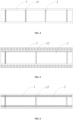
FIG. 1 is a schematic diagram of a noise reduction device according to an embodiment of the present disclosure; -
FIG. 2 is a schematic diagram of a trajectory of foams in a noise reduction device according to an embodiment of the present disclosure; -
FIG. 3 is a schematic diagram of a noise reduction device with different numbers of porous wire meshes according to an embodiment of the present disclosure; -
FIG. 4 is a schematic diagram of a noise reduction device with a limiting slot according to an embodiment of the present disclosure; -
FIGs. 5 and 6 are schematic diagrams of a noise reduction device with a sound-absorbing layer according to an embodiment of the present disclosure; -
FIG. 7 is a schematic diagram of a connecting device of a noise reduction device according to an embodiment of the present disclosure; and -
FIG. 8 is a schematic diagram of a connecting device of a noise reduction device according to another embodiment of the present disclosure. - In order to make objectives, technical solutions, and advantages of the present application clearer, the technical solutions of the present application will be clearly and completely described below in conjunction with the specific embodiments of the present application and the corresponding accompanying drawings. Obviously, the described embodiments are only a part of the embodiments of the present application, rather than all the embodiments. Based on the embodiments in present application, all other embodiments obtained by those of ordinary skill in the art without creative work shall fall within the protection scope of the present application.
- The following describes the embodiments of the present disclosure in detail. Examples of the embodiments are shown in the accompanying drawings, in which the same or similar reference numerals indicate the same or similar elements or elements with the same or similar functions through the whole text. The embodiments described below with reference to the accompanying drawings are exemplary, and are merely intended to explain the present disclosure and shall not be understood as a limitation to the present disclosure.
- For the convenience of description, the terms such as "upper", "lower", "rear" and "front" are used here, which denote spatial relative positions, describe the relationship of one unit or feature relative to another unit or feature in the accompanying drawings for description. The terms of the spatial relative positions may be intended to include different orientations of the equipment in use or operation other than the orientations shown in the accompanying drawings. For example, if a device in the accompanying drawings is turned upside down, the unit described as being located on "below" or "above" other units or features will be located "above" or "below" the other units or features. Therefore, the exemplary term "below" can encompass both spatial orientations of below and above.
- As shown in
FIG. 1 , the present disclosure provides a noise reduction device. The noise reduction device includes anouter connecting tube 1, and the outer connecting tube includes afirst end 11 connected to a capillary tube and asecond end 12 connected to an evaporator. A plurality ofporous wire meshes 2 arranged at intervals is deposed in the outer connecting tube, and side edges of theporous wire meshes 2 abut against an inner wall surface of the outer connectingtube 1. - Pore diameters of the plurality of
porous wire meshes 2 are reduced sequentially from thefirst end 11 to thesecond end 12. - An outer contour of the
porous wire mesh 2 is circular, and an outer diameter thereof is equal to an inner diameter of the outer connectingtube 1. That is, the plane in which theporous wire meshes 2 is disposed is perpendicular to an axis of the outer connectingtube 1. - Specifically, in this embodiment, there are three
porous wire meshes 2, which are a firstporous wire mesh 21 adjacent to thefirst end 11, a secondporous wire mesh 22 disposed in the middle of theouter connecting tube 1 and a thirdporous wire mesh 23 adjacent to thesecond end 12. The pore diameters of the firstporous wire mesh 21, the secondporous wire mesh 22 and the thirdporous wire mesh 23 are sequentially reduced. - As shown in
FIG. 2 , after a refrigerant forms bubbles at an ejection port of the capillary tube, the bubbles may be formed as bubbles large in volume due to the reduction in pressure. After passing through holes of theporous wire meshes 2, the large bubbles are dispersed and reconstituted to form small bubbles, such that the volume of the small bubbles can be gradually reduced after passing through theporous wire meshes 2 having gradually reduced pore diameters. Compared with large bubbles, small bubbles release less energy when broken, such that the vibration noise generated by the small bubbles when broken is much smaller than that of the large bubbles, thereby having an obvious noise reduction effect. In addition, the plurality ofporous wire meshes 2 enables the volume of the bubbles to be gradually changed in a gentle manner, which reduces the occurrence of situations in which the bubbles are suddenly broken while being in contact with theporous wire meshes 2 and being in movement. Thus, the large bubble can be transformed into bubbles small in volume as much as possible, thereby further improving the noise reduction effect. - Of course, the number of the
porous wire meshes 2 is not limited thereto, and the number of theporous wire meshes 2 can be adjusted according to the volume size of the refrigeration device, the diameter of the capillary tube, the type of the refrigerant, and other factors. As shown inFIG. 3 , in another embodiment of the disclosure, fourporous wire meshes 2 are evenly disposed inside the outer connectingtube 1 to further enable changes in volume of the bubbles to be gentle. - The
porous wire mesh 2 is made of a hydrophobic material to prevent the refrigerant from causing a destructive effect on the pore structure of theporous wire mesh 2. - Preferably, in this embodiment, the
porous wire mesh 2 is a metal wire mesh, such as a stainless-steel wire mesh and a copper wire mesh. Theporous wire mesh 2 made of metal has a higher structural strength, which can effectively prolong the service life of the noise reduction device. - According to some embodiments of the present disclosure, the outer connecting
tube 1 further sleeves a plurality of inner connectingtubes 3, and two adjacentinner connecting tubes 3 abut against two opposite end surfaces of each of theporous wire meshes 2, respectively. - Further, an outer diameter of the inner connecting
tube 3 is equal to an inner diameter of theouter connecting tube 1. - The plurality of inner connecting
tubes 3 matched with the outer connectingtube 1 in size is disposed in theouter connecting tube 1, theporous wire mesh 2 can be fixed and limited in position through theinner connecting tube 3, such that theporous wire mesh 2 can be prevented from deviating from its position under the impact of a large amount of foams, thereby keeping the structure of the noise reduction device stable. Moreover, the sleeving structure for the inner connectingtube 3 and the outer connectingtube 1 is simple and easy to implement. - Further, according to some embodiments of the present disclosure, the outer connecting
tube 1 and the inner connectingtube 3 are flexible tubes such as a flexible rubber tube, and can cooperate with the thin layer structure of theporous wire mesh 2 to enable the noise reduction device to be bent at will, such that the noise reduction device can be adapted to the internal structure of different refrigeration devices. - As shown in
FIG. 4 , according to some embodiments of the present disclosure, a plurality of limitingslots 11 may be provided on the inner wall surface of the outer connectingtube 1, and the diameter of theporous wire mesh 2 is an inner diameter of the limitingslot 11, such that the porous wire meshes 2 can be clamped in the limitingslots 11, and thus, the porous wire meshes 2 are fixed and limited in position. - As shown in
FIGs. 5 and 6 , according to some embodiments of the present disclosure, a sound-absorbinglayer 12 may also be provided on the outer side and/or inner side of the noise reduction device, and the sound-absorbinglayer 12 is filled with foams, porous material or the like, such that the noise reduction device can further play a role in noise reduction by absorbing noise. - As shown in
FIG. 7 , a plurality of connecting devices are provided at two ends of the noise reduction device, such that the noise reduction device can be connected and fixed to the capillary tube and the evaporator. - Each of the
first end 11 and thesecond end 12 sleeves aconnector 4, and theconnector 4 includes atubular fixing portion 41 disposed inside the inner connectingtube 3 and a flared connectingportion 42 protruding from the inner connectingtube 3. The outer wall surface of the fixingportion 41 abuts against the inner wall surface of the inner connectingtube 3. - Further, the outer connecting
tube 1 is further sleeved with alocking device 5 at an outer circumference corresponding to the fixingportion 41. Thelocking device 5 can be tightened inwards by an external force, such that thelocking device 5 and the fixingportion 41 can clamp the outer connectingtube 1 and the inner connectingtube 3 to achieve a tight connection between the noise reduction device and theconnector 4. - Furthermore, each of the
first end 11 and thesecond end 12 is further sleeved with a hollow bolt 6, and each of the capillary tube and the evaporator is provided with anut sleeve 7 matched with the hollow bolt 6. The hollow bolt 6 abutting against thelocking device 5 and pressing thelocking device 5 inwards. An outer diameter of the connectingportion 42 is smaller than an inner diameter of thenut sleeve 7. The connectingportion 42 abuts against the inner bottom surface of thenut sleeve 7, and its flared shape enables the connectingportion 42 to act like a funnel. Thenut sleeve 7 extends towards the middle of the noise reduction device to be connected to the hollow bolt 6 on the inner side of thelocking device 5. When the hollow bolt 6 is screwed in along the inner threads of thenut sleeve 7 and achieves a threaded tightening with thenut sleeve 7, the hollow bolt 6 exerts a force on thelocking device 5 to tighten thelocking device 5 inwards. - Specifically, according to this embodiment, the inner wall surface of the hollow bolt 6 is cylinder-shaped; the
locking device 5 is a frustum cone-shaped and low-stiffness metal structural member of which side surface facing the hollow bolt, and includes a first bottom surface 51 and a second bottom surface 52 opposite to each other. The first bottom surface 51 is close to the hollow bolt 6 and has a diameter smaller than an inner diameter of the hollow bolt 6, and a diameter of the second bottom surface 52 is larger than the inner diameter of the hollow bolt 6. An edge of an inner ring of the hollow bolt 6 abuts against to the side surface of thelocking device 5. When the hollow bolt 6 exerts a force on thelocking device 5, thelocking device 5 which is of a low-stiffness metal structure such as a copper structure may be deformed and tightened inwards, thereby achieving the tight locking function in conjunction with theconnector 4. - As shown in
FIG. 8 , according to another embodiment of the present disclosure, thelocking device 5 is a hollow cylinder-shaped metal structural member and provided with a plurality of notches at an end facing the hollow bolt 6. An inner wall surface of the hollow bolt 6 is frustum cone-shaped, and a side surface of the hollow bolt 6 faces thelocking device 5. An inner diameter of the end of the hollow bolt 6 close to thelocking device 5 is larger than an outer diameter of thelocking device 5, and a diameter of an opposite end of the hollow bolt 6 is smaller than the outer diameter of thelocking device 5. The edge of thelocking device 5 abuts against the inner wall surface of the hollow bolt 6. When the hollow bolt 6 exerts a force on thelocking device 5, the portion of the notches of thelocking device 5 contract, and thelocking device 5 is pressed inwards and thereby achieves the tight locking function in conjunction with theconnector 4. - The present disclosure further provides a refrigeration device, which includes a capillary tube and an evaporator. The refrigeration device further includes the noise reduction device as described above, and the noise reduction device is connected to the capillary tube and the evaporator.
- In summary, by providing the plurality of porous wire meshes having gradually changing pore diameters in the outer connecting tube to form the noise reduction device connected to the capillary tube and the evaporator according to the present disclosure, large bubbles formed at an ejection port of the capillary tube can be gradually dispersed and reconstituted to form small bubbles when passing through the noise reduction device, such that the noise generated when the bubbles are broken can be reduced, thereby playing a role in noise reduction.
- It should be understood that although the present disclosure is described in terms of embodiments in this Description, not every embodiment includes only one independent technical solution. The statement mode of the Description is merely for the sake of clarity, and those skilled in the art should regard the Description as a whole. The technical solutions in respective embodiments may also be combined properly to form other embodiments that can be understood by those skilled in the art.
- The series of detailed illustration listed above are merely specific illustrations of feasible embodiments of the present disclosure, and are not intended to limit the protection scope of the present disclosure. Any equivalent embodiments or modifications made without departing from the technical spirit of the present disclosure shall fall within the protection scope of the present disclosure.
Claims (10)
- A noise reduction device, comprising: an outer connecting tube, whereinthe outer connecting tube comprises a first end connected to a capillary tube and a second end connected to an evaporator, wherein a plurality of porous wire meshes arranged at an interval is disposed in the outer connecting tube, and side edges of the porous wire meshes abut against an inner wall surface of the outer connecting tube; andpore diameters of the plurality of porous wire meshes are gradually reduced from the first end to the second end.
- The noise reduction device according to claim 1, wherein the porous wire meshes comprise a first porous wire mesh adjacent to the first end, a second porous wire mesh disposed in a middle of the outer connecting tube and a third porous wire mesh adjacent to the second end; and pore diameters of the first porous wire mesh, the second porous wire mesh and the third porous wire mesh are sequentially reduced.
- The noise reduction device according to claim 1, wherein the outer connecting tube further sleeves a plurality of inner connecting tubes, and two adjacent inner connecting tubes abut against two opposite end surfaces of one of the porous wire meshes, respectively.
- The noise reduction device according to claim 3, wherein the outer connecting tube and the inner connecting tube are flexible tubes, and an outer diameter of the inner connecting tube is equal to an inner diameter of the outer connecting tube.
- The noise reduction device according to claim 3, wherein each of the first end and the second end further sleeves a connector, and the connector comprises a tubular fixing portion disposed inside the inner connecting tube and a flared connecting portion protruding from the inner connecting tube.
- The noise reduction device according to claim 5, wherein the outer connecting tube is further sleeved with a locking device at an outer circumference corresponding to the fixing portion.
- The noise reduction device according to claim 6, wherein each of the first end and the second end is further sleeved with a hollow bolt, and each of the capillary tube and the evaporator is provided with a nut sleeve matched with the hollow bolt, the hollow bolt abutting against the locking device to press the locking device inwards.
- The noise reduction device according to claim 7, wherein an inner wall surface of the hollow bolt is cylinder-shaped; the locking device is a frustum cone-shaped and low-stiffness metal structural member of which side surface faces the hollow bolt, and comprises a first bottom surface and a second bottom surface opposite to each other, wherein the first bottom surface is close to the hollow bolt and has a diameter smaller than an inner diameter of the hollow bolt, and a diameter of the second bottom surface is larger than the inner diameter of the hollow bolt.
- The noise reduction device according to claim 7, wherein the locking device is a hollow cylinder-shaped metal structural member and provided with a plurality of notches at an end facing the hollow bolt; an inner wall surface of the hollow bolt is frustum cone-shaped, and a side surface of the hollow bolt faces the locking device; and an inner diameter of an end of the hollow bolt close to the locking device is larger than an outer diameter of the locking device, and a diameter of an opposite end of the hollow bolt is smaller than the outer diameter of the locking device.
- A refrigeration device, comprising a capillary tube and an evaporator, wherein the refrigeration device further comprises the noise reduction device according to any one of claims 1 to 9, and the noise reduction device is connected to the capillary tube and the evaporator.
Applications Claiming Priority (2)
| Application Number | Priority Date | Filing Date | Title |
|---|---|---|---|
| CN202022344941.0U CN213778257U (en) | 2020-10-20 | 2020-10-20 | Noise reduction device and refrigerating device with same |
| PCT/CN2021/107023 WO2022083189A1 (en) | 2020-10-20 | 2021-07-19 | Noise reduction device and refrigeration device having same |
Publications (2)
| Publication Number | Publication Date |
|---|---|
| EP4206563A1 true EP4206563A1 (en) | 2023-07-05 |
| EP4206563A4 EP4206563A4 (en) | 2024-03-20 |
Family
ID=76909885
Family Applications (1)
| Application Number | Title | Priority Date | Filing Date |
|---|---|---|---|
| EP21881609.8A Pending EP4206563A4 (en) | 2020-10-20 | 2021-07-19 | Noise reduction device and refrigeration device having same |
Country Status (6)
| Country | Link |
|---|---|
| US (1) | US20230383888A1 (en) |
| EP (1) | EP4206563A4 (en) |
| JP (1) | JP7528381B2 (en) |
| CN (1) | CN213778257U (en) |
| AU (1) | AU2021363392B2 (en) |
| WO (1) | WO2022083189A1 (en) |
Families Citing this family (1)
| Publication number | Priority date | Publication date | Assignee | Title |
|---|---|---|---|---|
| CN114857666B (en) * | 2022-05-31 | 2023-08-01 | 青岛海信日立空调系统有限公司 | A multi-connected air conditioner |
Family Cites Families (21)
| Publication number | Priority date | Publication date | Assignee | Title |
|---|---|---|---|---|
| GB819402A (en) * | 1956-07-07 | 1959-09-02 | Electrolux Ltd | Improvements in or relating to absorption refrigerating apparatus |
| FR2055030A5 (en) * | 1969-07-15 | 1971-05-07 | Dunlop Co Ltd | Gas pressure reducing device |
| JP3554384B2 (en) * | 1994-12-09 | 2004-08-18 | 東芝キヤリア株式会社 | Indoor unit of air conditioner |
| JPH11325655A (en) * | 1998-05-14 | 1999-11-26 | Matsushita Seiko Co Ltd | Silencers and air conditioners |
| JP2006336992A (en) * | 2005-06-06 | 2006-12-14 | Matsushita Electric Ind Co Ltd | Air conditioner |
| KR101253634B1 (en) * | 2006-01-24 | 2013-04-10 | 엘지전자 주식회사 | air conditioner |
| US20100254758A1 (en) * | 2009-04-06 | 2010-10-07 | International Business Machines Corporation | Apparatus and method for forming a mechanical, fluid-tight connection |
| CN203436657U (en) * | 2013-08-20 | 2014-02-19 | 宁波圣宇瑞医疗器械有限公司 | Novel humidification bottle capable of eliminating noise by repeatedly cutting bubbles |
| CN203517046U (en) * | 2013-10-14 | 2014-04-02 | 宁海开泰管业科技有限公司 | Ripple type gas appliance stainless steel ripple hose |
| EP3064868B1 (en) * | 2013-10-29 | 2021-01-20 | Mitsubishi Electric Corporation | Expansion valve |
| EP2918952A1 (en) * | 2014-03-12 | 2015-09-16 | Whirlpool Corporation | Refrigerant circuit and refrigerator using such circuit |
| KR102257508B1 (en) * | 2014-06-24 | 2021-05-31 | 엘지전자 주식회사 | A linear compressor and a refrigerator including the same |
| CN204574646U (en) * | 2015-02-14 | 2015-08-19 | 浙江同星制冷有限公司 | A kind of choke valve with denoising structure |
| CN110068178A (en) * | 2018-01-24 | 2019-07-30 | 富泰华工业(深圳)有限公司 | Noise reduction device and refrigeration equipment with the noise reduction device |
| CN110296264B (en) * | 2018-03-23 | 2022-02-08 | 浙江三花智能控制股份有限公司 | Electronic expansion valve |
| KR101879248B1 (en) * | 2018-04-23 | 2018-07-17 | 오형동 | Connecting structure of refrigerant pipe |
| US11906081B2 (en) * | 2018-12-20 | 2024-02-20 | Mitsubishi Electric Corporation | Pipe joint structure and air conditioner |
| JP6678981B1 (en) * | 2019-12-23 | 2020-04-15 | 井上スダレ株式会社 | Refrigerant pipe joint structure |
| CN111664312A (en) * | 2020-04-17 | 2020-09-15 | 广东粤电靖海发电有限公司 | Multistage subdivision formula rivers straightening device |
| CN112082033A (en) * | 2020-08-24 | 2020-12-15 | 珠海格力电器股份有限公司 | Pipeline vibration damper and air conditioner |
| CN114636337A (en) * | 2020-12-15 | 2022-06-17 | 全亿大科技(佛山)有限公司 | Heat pipe, and manufacturing method and device of heat pipe |
-
2020
- 2020-10-20 CN CN202022344941.0U patent/CN213778257U/en active Active
-
2021
- 2021-07-19 US US18/032,803 patent/US20230383888A1/en active Pending
- 2021-07-19 JP JP2023548989A patent/JP7528381B2/en active Active
- 2021-07-19 EP EP21881609.8A patent/EP4206563A4/en active Pending
- 2021-07-19 WO PCT/CN2021/107023 patent/WO2022083189A1/en not_active Ceased
- 2021-07-19 AU AU2021363392A patent/AU2021363392B2/en active Active
Also Published As
| Publication number | Publication date |
|---|---|
| US20230383888A1 (en) | 2023-11-30 |
| AU2021363392A1 (en) | 2023-06-01 |
| EP4206563A4 (en) | 2024-03-20 |
| WO2022083189A1 (en) | 2022-04-28 |
| JP2023546738A (en) | 2023-11-07 |
| CN213778257U (en) | 2021-07-23 |
| JP7528381B2 (en) | 2024-08-05 |
| AU2021363392A9 (en) | 2024-09-12 |
| AU2021363392B2 (en) | 2024-07-18 |
| NZ799147A (en) | 2025-02-28 |
Similar Documents
| Publication | Publication Date | Title |
|---|---|---|
| US7331195B2 (en) | Refrigerant distribution device and method | |
| JP3376534B2 (en) | Refrigerant distributor | |
| EP1794513B1 (en) | Refrigerant distribution device and method | |
| US10228148B2 (en) | Methods and apparatuses to isolate vibration | |
| US9845973B2 (en) | Cascade refrigeration system | |
| EP4206563A1 (en) | Noise reduction device and refrigeration device having same | |
| EP4220039A1 (en) | Refrigeration system and refrigeration appliance having same | |
| WO2003038278A2 (en) | Multiple compressor common circuit structure design | |
| JP2827404B2 (en) | Refrigerant condenser | |
| KR101864279B1 (en) | Coolant distributor and Connecting tube for coolant distributor | |
| CN207778909U (en) | refrigerator | |
| NZ799147A9 (en) | Noise reduction device and refrigeration device having same | |
| CN209893691U (en) | Knockout and have its refrigerating system | |
| EP4105576B1 (en) | Economizer for refrigeration system and refrigeration system | |
| CN115218565A (en) | Throttling pipeline vibration damping fixtures, refrigeration systems and refrigeration appliances | |
| CN209706403U (en) | refrigerator | |
| CN215597889U (en) | Throttling pipeline vibration damping fixtures, refrigeration systems and refrigeration appliances | |
| CN207716692U (en) | A kind of qi leel, oil end cap | |
| KR20160058535A (en) | An outdoor unit for a an air conditioner | |
| WO2005008152A1 (en) | Evaporator for a refrigeration appliance | |
| CN215260738U (en) | Refrigeration system and refrigeration appliance with the same | |
| WO2021153244A1 (en) | Air conditioner sound muffler and air conditioner | |
| CN208419299U (en) | A kind of refrigeration equipment capillary | |
| CN207778910U (en) | Refrigerator | |
| JP2503138Y2 (en) | Refrigeration equipment |
Legal Events
| Date | Code | Title | Description |
|---|---|---|---|
| STAA | Information on the status of an ep patent application or granted ep patent |
Free format text: STATUS: THE INTERNATIONAL PUBLICATION HAS BEEN MADE |
|
| PUAI | Public reference made under article 153(3) epc to a published international application that has entered the european phase |
Free format text: ORIGINAL CODE: 0009012 |
|
| STAA | Information on the status of an ep patent application or granted ep patent |
Free format text: STATUS: REQUEST FOR EXAMINATION WAS MADE |
|
| 17P | Request for examination filed |
Effective date: 20230330 |
|
| AK | Designated contracting states |
Kind code of ref document: A1 Designated state(s): AL AT BE BG CH CY CZ DE DK EE ES FI FR GB GR HR HU IE IS IT LI LT LU LV MC MK MT NL NO PL PT RO RS SE SI SK SM TR |
|
| DAV | Request for validation of the european patent (deleted) | ||
| DAX | Request for extension of the european patent (deleted) | ||
| A4 | Supplementary search report drawn up and despatched |
Effective date: 20240219 |
|
| RIC1 | Information provided on ipc code assigned before grant |
Ipc: F01N 1/08 20060101ALI20240213BHEP Ipc: F25B 41/40 20210101ALI20240213BHEP Ipc: F16L 19/02 20060101ALI20240213BHEP Ipc: F25B 41/00 20210101AFI20240213BHEP |
|
| STAA | Information on the status of an ep patent application or granted ep patent |
Free format text: STATUS: EXAMINATION IS IN PROGRESS |
|
| 17Q | First examination report despatched |
Effective date: 20260223 |