EP4206561A1 - Gas bearing management for a compressor - Google Patents
Gas bearing management for a compressor Download PDFInfo
- Publication number
- EP4206561A1 EP4206561A1 EP22213795.2A EP22213795A EP4206561A1 EP 4206561 A1 EP4206561 A1 EP 4206561A1 EP 22213795 A EP22213795 A EP 22213795A EP 4206561 A1 EP4206561 A1 EP 4206561A1
- Authority
- EP
- European Patent Office
- Prior art keywords
- compressor
- pressure
- gas
- gas bearing
- speed limit
- Prior art date
- Legal status (The legal status is an assumption and is not a legal conclusion. Google has not performed a legal analysis and makes no representation as to the accuracy of the status listed.)
- Granted
Links
Images


Classifications
-
- F—MECHANICAL ENGINEERING; LIGHTING; HEATING; WEAPONS; BLASTING
- F04—POSITIVE - DISPLACEMENT MACHINES FOR LIQUIDS; PUMPS FOR LIQUIDS OR ELASTIC FLUIDS
- F04D—NON-POSITIVE-DISPLACEMENT PUMPS
- F04D25/00—Pumping installations or systems
- F04D25/02—Units comprising pumps and their driving means
- F04D25/06—Units comprising pumps and their driving means the pump being electrically driven
- F04D25/0606—Units comprising pumps and their driving means the pump being electrically driven the electric motor being specially adapted for integration in the pump
-
- F—MECHANICAL ENGINEERING; LIGHTING; HEATING; WEAPONS; BLASTING
- F25—REFRIGERATION OR COOLING; COMBINED HEATING AND REFRIGERATION SYSTEMS; HEAT PUMP SYSTEMS; MANUFACTURE OR STORAGE OF ICE; LIQUEFACTION SOLIDIFICATION OF GASES
- F25B—REFRIGERATION MACHINES, PLANTS OR SYSTEMS; COMBINED HEATING AND REFRIGERATION SYSTEMS; HEAT PUMP SYSTEMS
- F25B41/00—Fluid-circulation arrangements
- F25B41/20—Disposition of valves, e.g. of on-off valves or flow control valves
-
- F—MECHANICAL ENGINEERING; LIGHTING; HEATING; WEAPONS; BLASTING
- F25—REFRIGERATION OR COOLING; COMBINED HEATING AND REFRIGERATION SYSTEMS; HEAT PUMP SYSTEMS; MANUFACTURE OR STORAGE OF ICE; LIQUEFACTION SOLIDIFICATION OF GASES
- F25B—REFRIGERATION MACHINES, PLANTS OR SYSTEMS; COMBINED HEATING AND REFRIGERATION SYSTEMS; HEAT PUMP SYSTEMS
- F25B41/00—Fluid-circulation arrangements
- F25B41/40—Fluid line arrangements
-
- F—MECHANICAL ENGINEERING; LIGHTING; HEATING; WEAPONS; BLASTING
- F04—POSITIVE - DISPLACEMENT MACHINES FOR LIQUIDS; PUMPS FOR LIQUIDS OR ELASTIC FLUIDS
- F04D—NON-POSITIVE-DISPLACEMENT PUMPS
- F04D17/00—Radial-flow pumps, e.g. centrifugal pumps; Helico-centrifugal pumps
- F04D17/08—Centrifugal pumps
- F04D17/10—Centrifugal pumps for compressing or evacuating
- F04D17/12—Multi-stage pumps
- F04D17/122—Multi-stage pumps the individual rotor discs being, one for each stage, on a common shaft and axially spaced, e.g. conventional centrifugal multi- stage compressors
-
- F—MECHANICAL ENGINEERING; LIGHTING; HEATING; WEAPONS; BLASTING
- F04—POSITIVE - DISPLACEMENT MACHINES FOR LIQUIDS; PUMPS FOR LIQUIDS OR ELASTIC FLUIDS
- F04D—NON-POSITIVE-DISPLACEMENT PUMPS
- F04D27/00—Control, e.g. regulation, of pumps, pumping installations or pumping systems specially adapted for elastic fluids
-
- F—MECHANICAL ENGINEERING; LIGHTING; HEATING; WEAPONS; BLASTING
- F04—POSITIVE - DISPLACEMENT MACHINES FOR LIQUIDS; PUMPS FOR LIQUIDS OR ELASTIC FLUIDS
- F04D—NON-POSITIVE-DISPLACEMENT PUMPS
- F04D27/00—Control, e.g. regulation, of pumps, pumping installations or pumping systems specially adapted for elastic fluids
- F04D27/02—Surge control
- F04D27/0261—Surge control by varying driving speed
-
- F—MECHANICAL ENGINEERING; LIGHTING; HEATING; WEAPONS; BLASTING
- F04—POSITIVE - DISPLACEMENT MACHINES FOR LIQUIDS; PUMPS FOR LIQUIDS OR ELASTIC FLUIDS
- F04D—NON-POSITIVE-DISPLACEMENT PUMPS
- F04D29/00—Details, component parts, or accessories
- F04D29/05—Shafts or bearings, or assemblies thereof, specially adapted for elastic fluid pumps
- F04D29/051—Axial thrust balancing
- F04D29/0513—Axial thrust balancing hydrostatic; hydrodynamic thrust bearings
-
- F—MECHANICAL ENGINEERING; LIGHTING; HEATING; WEAPONS; BLASTING
- F04—POSITIVE - DISPLACEMENT MACHINES FOR LIQUIDS; PUMPS FOR LIQUIDS OR ELASTIC FLUIDS
- F04D—NON-POSITIVE-DISPLACEMENT PUMPS
- F04D29/00—Details, component parts, or accessories
- F04D29/05—Shafts or bearings, or assemblies thereof, specially adapted for elastic fluid pumps
- F04D29/056—Bearings
-
- F—MECHANICAL ENGINEERING; LIGHTING; HEATING; WEAPONS; BLASTING
- F04—POSITIVE - DISPLACEMENT MACHINES FOR LIQUIDS; PUMPS FOR LIQUIDS OR ELASTIC FLUIDS
- F04D—NON-POSITIVE-DISPLACEMENT PUMPS
- F04D29/00—Details, component parts, or accessories
- F04D29/05—Shafts or bearings, or assemblies thereof, specially adapted for elastic fluid pumps
- F04D29/056—Bearings
- F04D29/057—Bearings hydrostatic; hydrodynamic
-
- F—MECHANICAL ENGINEERING; LIGHTING; HEATING; WEAPONS; BLASTING
- F04—POSITIVE - DISPLACEMENT MACHINES FOR LIQUIDS; PUMPS FOR LIQUIDS OR ELASTIC FLUIDS
- F04D—NON-POSITIVE-DISPLACEMENT PUMPS
- F04D29/00—Details, component parts, or accessories
- F04D29/06—Lubrication
- F04D29/063—Lubrication specially adapted for elastic fluid pumps
-
- F—MECHANICAL ENGINEERING; LIGHTING; HEATING; WEAPONS; BLASTING
- F04—POSITIVE - DISPLACEMENT MACHINES FOR LIQUIDS; PUMPS FOR LIQUIDS OR ELASTIC FLUIDS
- F04D—NON-POSITIVE-DISPLACEMENT PUMPS
- F04D29/00—Details, component parts, or accessories
- F04D29/26—Rotors specially for elastic fluids
- F04D29/28—Rotors specially for elastic fluids for centrifugal or helico-centrifugal pumps for radial-flow or helico-centrifugal pumps
- F04D29/284—Rotors specially for elastic fluids for centrifugal or helico-centrifugal pumps for radial-flow or helico-centrifugal pumps for compressors
- F04D29/286—Rotors specially for elastic fluids for centrifugal or helico-centrifugal pumps for radial-flow or helico-centrifugal pumps for compressors multi-stage rotors
-
- F—MECHANICAL ENGINEERING; LIGHTING; HEATING; WEAPONS; BLASTING
- F04—POSITIVE - DISPLACEMENT MACHINES FOR LIQUIDS; PUMPS FOR LIQUIDS OR ELASTIC FLUIDS
- F04D—NON-POSITIVE-DISPLACEMENT PUMPS
- F04D29/00—Details, component parts, or accessories
- F04D29/40—Casings; Connections of working fluid
- F04D29/42—Casings; Connections of working fluid for radial or helico-centrifugal pumps
- F04D29/4206—Casings; Connections of working fluid for radial or helico-centrifugal pumps especially adapted for elastic fluid pumps
-
- F—MECHANICAL ENGINEERING; LIGHTING; HEATING; WEAPONS; BLASTING
- F04—POSITIVE - DISPLACEMENT MACHINES FOR LIQUIDS; PUMPS FOR LIQUIDS OR ELASTIC FLUIDS
- F04D—NON-POSITIVE-DISPLACEMENT PUMPS
- F04D29/00—Details, component parts, or accessories
- F04D29/58—Cooling; Heating; Diminishing heat transfer
- F04D29/5806—Cooling the drive system
-
- F—MECHANICAL ENGINEERING; LIGHTING; HEATING; WEAPONS; BLASTING
- F16—ENGINEERING ELEMENTS AND UNITS; GENERAL MEASURES FOR PRODUCING AND MAINTAINING EFFECTIVE FUNCTIONING OF MACHINES OR INSTALLATIONS; THERMAL INSULATION IN GENERAL
- F16C—SHAFTS; FLEXIBLE SHAFTS; ELEMENTS OR CRANKSHAFT MECHANISMS; ROTARY BODIES OTHER THAN GEARING ELEMENTS; BEARINGS
- F16C27/00—Elastic or yielding bearings or bearing supports, for exclusively rotary movement
-
- F—MECHANICAL ENGINEERING; LIGHTING; HEATING; WEAPONS; BLASTING
- F16—ENGINEERING ELEMENTS AND UNITS; GENERAL MEASURES FOR PRODUCING AND MAINTAINING EFFECTIVE FUNCTIONING OF MACHINES OR INSTALLATIONS; THERMAL INSULATION IN GENERAL
- F16C—SHAFTS; FLEXIBLE SHAFTS; ELEMENTS OR CRANKSHAFT MECHANISMS; ROTARY BODIES OTHER THAN GEARING ELEMENTS; BEARINGS
- F16C32/00—Bearings not otherwise provided for
- F16C32/06—Bearings not otherwise provided for with moving member supported by a fluid cushion formed, at least to a large extent, otherwise than by movement of the shaft, e.g. hydrostatic air-cushion bearings
- F16C32/0603—Bearings not otherwise provided for with moving member supported by a fluid cushion formed, at least to a large extent, otherwise than by movement of the shaft, e.g. hydrostatic air-cushion bearings supported by a gas cushion, e.g. an air cushion
- F16C32/0614—Bearings not otherwise provided for with moving member supported by a fluid cushion formed, at least to a large extent, otherwise than by movement of the shaft, e.g. hydrostatic air-cushion bearings supported by a gas cushion, e.g. an air cushion the gas being supplied under pressure, e.g. aerostatic bearings
-
- F—MECHANICAL ENGINEERING; LIGHTING; HEATING; WEAPONS; BLASTING
- F16—ENGINEERING ELEMENTS AND UNITS; GENERAL MEASURES FOR PRODUCING AND MAINTAINING EFFECTIVE FUNCTIONING OF MACHINES OR INSTALLATIONS; THERMAL INSULATION IN GENERAL
- F16C—SHAFTS; FLEXIBLE SHAFTS; ELEMENTS OR CRANKSHAFT MECHANISMS; ROTARY BODIES OTHER THAN GEARING ELEMENTS; BEARINGS
- F16C32/00—Bearings not otherwise provided for
- F16C32/06—Bearings not otherwise provided for with moving member supported by a fluid cushion formed, at least to a large extent, otherwise than by movement of the shaft, e.g. hydrostatic air-cushion bearings
- F16C32/0603—Bearings not otherwise provided for with moving member supported by a fluid cushion formed, at least to a large extent, otherwise than by movement of the shaft, e.g. hydrostatic air-cushion bearings supported by a gas cushion, e.g. an air cushion
- F16C32/0614—Bearings not otherwise provided for with moving member supported by a fluid cushion formed, at least to a large extent, otherwise than by movement of the shaft, e.g. hydrostatic air-cushion bearings supported by a gas cushion, e.g. an air cushion the gas being supplied under pressure, e.g. aerostatic bearings
- F16C32/0618—Bearings not otherwise provided for with moving member supported by a fluid cushion formed, at least to a large extent, otherwise than by movement of the shaft, e.g. hydrostatic air-cushion bearings supported by a gas cushion, e.g. an air cushion the gas being supplied under pressure, e.g. aerostatic bearings via porous material
-
- F—MECHANICAL ENGINEERING; LIGHTING; HEATING; WEAPONS; BLASTING
- F16—ENGINEERING ELEMENTS AND UNITS; GENERAL MEASURES FOR PRODUCING AND MAINTAINING EFFECTIVE FUNCTIONING OF MACHINES OR INSTALLATIONS; THERMAL INSULATION IN GENERAL
- F16C—SHAFTS; FLEXIBLE SHAFTS; ELEMENTS OR CRANKSHAFT MECHANISMS; ROTARY BODIES OTHER THAN GEARING ELEMENTS; BEARINGS
- F16C32/00—Bearings not otherwise provided for
- F16C32/06—Bearings not otherwise provided for with moving member supported by a fluid cushion formed, at least to a large extent, otherwise than by movement of the shaft, e.g. hydrostatic air-cushion bearings
- F16C32/0629—Bearings not otherwise provided for with moving member supported by a fluid cushion formed, at least to a large extent, otherwise than by movement of the shaft, e.g. hydrostatic air-cushion bearings supported by a liquid cushion, e.g. oil cushion
- F16C32/064—Bearings not otherwise provided for with moving member supported by a fluid cushion formed, at least to a large extent, otherwise than by movement of the shaft, e.g. hydrostatic air-cushion bearings supported by a liquid cushion, e.g. oil cushion the liquid being supplied under pressure
-
- F—MECHANICAL ENGINEERING; LIGHTING; HEATING; WEAPONS; BLASTING
- F16—ENGINEERING ELEMENTS AND UNITS; GENERAL MEASURES FOR PRODUCING AND MAINTAINING EFFECTIVE FUNCTIONING OF MACHINES OR INSTALLATIONS; THERMAL INSULATION IN GENERAL
- F16C—SHAFTS; FLEXIBLE SHAFTS; ELEMENTS OR CRANKSHAFT MECHANISMS; ROTARY BODIES OTHER THAN GEARING ELEMENTS; BEARINGS
- F16C32/00—Bearings not otherwise provided for
- F16C32/06—Bearings not otherwise provided for with moving member supported by a fluid cushion formed, at least to a large extent, otherwise than by movement of the shaft, e.g. hydrostatic air-cushion bearings
- F16C32/0662—Details of hydrostatic bearings independent of fluid supply or direction of load
-
- F—MECHANICAL ENGINEERING; LIGHTING; HEATING; WEAPONS; BLASTING
- F16—ENGINEERING ELEMENTS AND UNITS; GENERAL MEASURES FOR PRODUCING AND MAINTAINING EFFECTIVE FUNCTIONING OF MACHINES OR INSTALLATIONS; THERMAL INSULATION IN GENERAL
- F16C—SHAFTS; FLEXIBLE SHAFTS; ELEMENTS OR CRANKSHAFT MECHANISMS; ROTARY BODIES OTHER THAN GEARING ELEMENTS; BEARINGS
- F16C32/00—Bearings not otherwise provided for
- F16C32/06—Bearings not otherwise provided for with moving member supported by a fluid cushion formed, at least to a large extent, otherwise than by movement of the shaft, e.g. hydrostatic air-cushion bearings
- F16C32/0681—Construction or mounting aspects of hydrostatic bearings, for exclusively rotary movement, related to the direction of load
- F16C32/0696—Construction or mounting aspects of hydrostatic bearings, for exclusively rotary movement, related to the direction of load for both radial and axial load
-
- F—MECHANICAL ENGINEERING; LIGHTING; HEATING; WEAPONS; BLASTING
- F25—REFRIGERATION OR COOLING; COMBINED HEATING AND REFRIGERATION SYSTEMS; HEAT PUMP SYSTEMS; MANUFACTURE OR STORAGE OF ICE; LIQUEFACTION SOLIDIFICATION OF GASES
- F25B—REFRIGERATION MACHINES, PLANTS OR SYSTEMS; COMBINED HEATING AND REFRIGERATION SYSTEMS; HEAT PUMP SYSTEMS
- F25B31/00—Compressor arrangements
- F25B31/002—Lubrication
-
- F—MECHANICAL ENGINEERING; LIGHTING; HEATING; WEAPONS; BLASTING
- F25—REFRIGERATION OR COOLING; COMBINED HEATING AND REFRIGERATION SYSTEMS; HEAT PUMP SYSTEMS; MANUFACTURE OR STORAGE OF ICE; LIQUEFACTION SOLIDIFICATION OF GASES
- F25B—REFRIGERATION MACHINES, PLANTS OR SYSTEMS; COMBINED HEATING AND REFRIGERATION SYSTEMS; HEAT PUMP SYSTEMS
- F25B49/00—Arrangement or mounting of control or safety devices
- F25B49/005—Arrangement or mounting of control or safety devices of safety devices
-
- F—MECHANICAL ENGINEERING; LIGHTING; HEATING; WEAPONS; BLASTING
- F04—POSITIVE - DISPLACEMENT MACHINES FOR LIQUIDS; PUMPS FOR LIQUIDS OR ELASTIC FLUIDS
- F04D—NON-POSITIVE-DISPLACEMENT PUMPS
- F04D27/00—Control, e.g. regulation, of pumps, pumping installations or pumping systems specially adapted for elastic fluids
- F04D27/004—Control, e.g. regulation, of pumps, pumping installations or pumping systems specially adapted for elastic fluids by varying driving speed
-
- F—MECHANICAL ENGINEERING; LIGHTING; HEATING; WEAPONS; BLASTING
- F16—ENGINEERING ELEMENTS AND UNITS; GENERAL MEASURES FOR PRODUCING AND MAINTAINING EFFECTIVE FUNCTIONING OF MACHINES OR INSTALLATIONS; THERMAL INSULATION IN GENERAL
- F16C—SHAFTS; FLEXIBLE SHAFTS; ELEMENTS OR CRANKSHAFT MECHANISMS; ROTARY BODIES OTHER THAN GEARING ELEMENTS; BEARINGS
- F16C2360/00—Engines or pumps
- F16C2360/44—Centrifugal pumps
-
- F—MECHANICAL ENGINEERING; LIGHTING; HEATING; WEAPONS; BLASTING
- F25—REFRIGERATION OR COOLING; COMBINED HEATING AND REFRIGERATION SYSTEMS; HEAT PUMP SYSTEMS; MANUFACTURE OR STORAGE OF ICE; LIQUEFACTION SOLIDIFICATION OF GASES
- F25B—REFRIGERATION MACHINES, PLANTS OR SYSTEMS; COMBINED HEATING AND REFRIGERATION SYSTEMS; HEAT PUMP SYSTEMS
- F25B1/00—Compression machines, plants or systems with non-reversible cycle
- F25B1/04—Compression machines, plants or systems with non-reversible cycle with compressor of rotary type
- F25B1/047—Compression machines, plants or systems with non-reversible cycle with compressor of rotary type of screw type
-
- F—MECHANICAL ENGINEERING; LIGHTING; HEATING; WEAPONS; BLASTING
- F25—REFRIGERATION OR COOLING; COMBINED HEATING AND REFRIGERATION SYSTEMS; HEAT PUMP SYSTEMS; MANUFACTURE OR STORAGE OF ICE; LIQUEFACTION SOLIDIFICATION OF GASES
- F25B—REFRIGERATION MACHINES, PLANTS OR SYSTEMS; COMBINED HEATING AND REFRIGERATION SYSTEMS; HEAT PUMP SYSTEMS
- F25B1/00—Compression machines, plants or systems with non-reversible cycle
- F25B1/04—Compression machines, plants or systems with non-reversible cycle with compressor of rotary type
- F25B1/053—Compression machines, plants or systems with non-reversible cycle with compressor of rotary type of turbine type
-
- F—MECHANICAL ENGINEERING; LIGHTING; HEATING; WEAPONS; BLASTING
- F25—REFRIGERATION OR COOLING; COMBINED HEATING AND REFRIGERATION SYSTEMS; HEAT PUMP SYSTEMS; MANUFACTURE OR STORAGE OF ICE; LIQUEFACTION SOLIDIFICATION OF GASES
- F25B—REFRIGERATION MACHINES, PLANTS OR SYSTEMS; COMBINED HEATING AND REFRIGERATION SYSTEMS; HEAT PUMP SYSTEMS
- F25B2400/00—Component parts or details not otherwise provided for in this subclass
- F25B2400/07—Details of compressors or related parts
-
- F—MECHANICAL ENGINEERING; LIGHTING; HEATING; WEAPONS; BLASTING
- F25—REFRIGERATION OR COOLING; COMBINED HEATING AND REFRIGERATION SYSTEMS; HEAT PUMP SYSTEMS; MANUFACTURE OR STORAGE OF ICE; LIQUEFACTION SOLIDIFICATION OF GASES
- F25B—REFRIGERATION MACHINES, PLANTS OR SYSTEMS; COMBINED HEATING AND REFRIGERATION SYSTEMS; HEAT PUMP SYSTEMS
- F25B2600/00—Control issues
- F25B2600/02—Compressor control
- F25B2600/025—Compressor control by controlling speed
-
- F—MECHANICAL ENGINEERING; LIGHTING; HEATING; WEAPONS; BLASTING
- F25—REFRIGERATION OR COOLING; COMBINED HEATING AND REFRIGERATION SYSTEMS; HEAT PUMP SYSTEMS; MANUFACTURE OR STORAGE OF ICE; LIQUEFACTION SOLIDIFICATION OF GASES
- F25B—REFRIGERATION MACHINES, PLANTS OR SYSTEMS; COMBINED HEATING AND REFRIGERATION SYSTEMS; HEAT PUMP SYSTEMS
- F25B2600/00—Control issues
- F25B2600/25—Control of valves
- F25B2600/2515—Flow valves
-
- F—MECHANICAL ENGINEERING; LIGHTING; HEATING; WEAPONS; BLASTING
- F25—REFRIGERATION OR COOLING; COMBINED HEATING AND REFRIGERATION SYSTEMS; HEAT PUMP SYSTEMS; MANUFACTURE OR STORAGE OF ICE; LIQUEFACTION SOLIDIFICATION OF GASES
- F25B—REFRIGERATION MACHINES, PLANTS OR SYSTEMS; COMBINED HEATING AND REFRIGERATION SYSTEMS; HEAT PUMP SYSTEMS
- F25B2700/00—Sensing or detecting of parameters; Sensors therefor
- F25B2700/19—Pressures
- F25B2700/193—Pressures of the compressor
- F25B2700/1931—Discharge pressures
-
- F—MECHANICAL ENGINEERING; LIGHTING; HEATING; WEAPONS; BLASTING
- F25—REFRIGERATION OR COOLING; COMBINED HEATING AND REFRIGERATION SYSTEMS; HEAT PUMP SYSTEMS; MANUFACTURE OR STORAGE OF ICE; LIQUEFACTION SOLIDIFICATION OF GASES
- F25B—REFRIGERATION MACHINES, PLANTS OR SYSTEMS; COMBINED HEATING AND REFRIGERATION SYSTEMS; HEAT PUMP SYSTEMS
- F25B2700/00—Sensing or detecting of parameters; Sensors therefor
- F25B2700/19—Pressures
- F25B2700/193—Pressures of the compressor
- F25B2700/1933—Suction pressures
-
- F—MECHANICAL ENGINEERING; LIGHTING; HEATING; WEAPONS; BLASTING
- F25—REFRIGERATION OR COOLING; COMBINED HEATING AND REFRIGERATION SYSTEMS; HEAT PUMP SYSTEMS; MANUFACTURE OR STORAGE OF ICE; LIQUEFACTION SOLIDIFICATION OF GASES
- F25B—REFRIGERATION MACHINES, PLANTS OR SYSTEMS; COMBINED HEATING AND REFRIGERATION SYSTEMS; HEAT PUMP SYSTEMS
- F25B41/00—Fluid-circulation arrangements
- F25B41/20—Disposition of valves, e.g. of on-off valves or flow control valves
- F25B41/22—Disposition of valves, e.g. of on-off valves or flow control valves between evaporator and compressor
-
- F—MECHANICAL ENGINEERING; LIGHTING; HEATING; WEAPONS; BLASTING
- F25—REFRIGERATION OR COOLING; COMBINED HEATING AND REFRIGERATION SYSTEMS; HEAT PUMP SYSTEMS; MANUFACTURE OR STORAGE OF ICE; LIQUEFACTION SOLIDIFICATION OF GASES
- F25B—REFRIGERATION MACHINES, PLANTS OR SYSTEMS; COMBINED HEATING AND REFRIGERATION SYSTEMS; HEAT PUMP SYSTEMS
- F25B49/00—Arrangement or mounting of control or safety devices
- F25B49/02—Arrangement or mounting of control or safety devices for compression type machines, plants or systems
- F25B49/022—Compressor control arrangements
Definitions
- HVACR heating, ventilation, air conditioning, and refrigeration
- a heating, ventilation, air conditioning, and refrigeration (HVACR) system generally includes a compressor.
- Compressors include one or more bearings for supporting its moving/rotating components within the compressor, such as but not limited to, a rotating driveshaft.
- a bearing can be a gas bearing that utilizes compressed gas to provide support to its moving/rotating component.
- a heating, ventilation, air conditioning, and refrigeration (HVACR) system includes a heat transfer circuit and a controller.
- the heat transfer circuit includes a compressor, a condenser, an expander, and an evaporator that are fluidly connected.
- the compressor includes a gas bearing, and one or more of the compressor and an external gas source is configured to supply compressed gas to the gas bearing.
- the controller is electrically connected to the compressor. The controller is configured to determine an inlet pressure of the compressed gas supplied to the gas bearing and an outlet pressure of the compressed gas exiting the gas bearing, determine a maximum speed limit for the compressor based on the inlet pressure and the outlet pressure, and prevent the compressor from operating at a speed that is greater than the maximum speed limit.
- a method of controlling a compressor includes supplying compressed gas to a gas bearing of the compressor.
- the method also includes determining, using a controller of the compressor: a speed setting for the compressor based on a cooling requirement, an inlet pressure of the compressed gas supplied to the gas bearing, an outlet pressure of compressed gas exiting the gas bearing.
- the method also includes calculating, using the controller of the compressor, a maximum speed limit for the compressor based on the inlet pressure of the compressed gas and the outlet pressure of the gas bearing.
- the method further includes that in response to determining that the speed setting is greater than the maximum speed limit as calculated, the controller adjusts operation of the compressor such that a speed of the compressor is at or below the maximum speed limit.
- HVAC heating, ventilation, air conditioning, and refrigeration
- the HVACR system includes a heat transfer circuit that includes a compressor and a working fluid (e.g., a refrigerant, a refrigerant mixture, or the like) that circulates through the heat transfer circuit.
- the working fluid is utilized to heat or cool a process fluid (e.g., air, water and/or glycol, or the like).
- the compressor includes components (e.g., driveshaft, scroll, rotor, screws, impeller, or the like) that move relative to the housing of the compressor to compress the working fluid.
- One or more gas bearing(s) are provided to support said components within the compressor.
- a gas bearing can be aerodynamic gas bearing, an aerostatic bearing, or a hybrid gas bearing.
- An aerodynamic gas bearing is a gas bearing that relies upon being provided with a supply of compressed gas to operate and provide support.
- a hybrid gas bearing is a gas bearing that can provide support during normal operation and relies upon being provided with a supply of compressed gas during the startup and shutdown of the compressor to provide support.
- An aerodynamic gas bearing is a gas bearing that does not utilize a supply of compressed gas to provide its support.
- the aerostatic and hybrid gas bearings are supplied with compressed gas which is utilized by the gas bearing(s) to provide adequate support to the moving components of the compressor.
- the compressed gas supplied to the aerostatic and hybrid gas bearing(s) can be a portion of the working fluid compressed by the compressor.
- Some operating conditions of the compressor such as but not limited to, when operated at higher speeds and/or when the gas bearing vents to a higher pressure, can cause sub synchronous instabilities in the gas bearing(s) that utilize the working fluid causing the support provided by the gas bearing(s) to become unstable. This instability in the gas bearing(s) can lead to failure of the gas bearing(s) and damage to the compressor.
- Embodiment described herein are directed to HVACR systems, compressors of HVACR systems, and methods of controlling a compressor of an HVACR system that operate in a manner that ensures stable operation of the gas bearing(s) in the compressor.
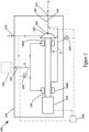
- FIG. 1 is a schematic diagram of a heat transfer circuit 1 of a HVACR system, according to an embodiment.
- the heat transfer circuit 1 includes a compressor 10, a condenser 20, an expansion device 30, and an evaporator 40.
- the heat transfer circuit 1 can be modified to include additional components.
- the heat transfer circuit 1 in an embodiment can include an economizer heat exchanger, one or more flow control devices, a receiver tank, a dryer, a suction-liquid heat exchanger, or the like.
- the components of the heat transfer circuit 1 are fluidly connected.
- the heat transfer circuit 1 can be configured as a cooling system (e.g., a fluid chiller of an HVACR, an air conditioning system, or the like) that can be operated in a cooling mode, and/or the heat transfer circuit 1 can be configured to operate as a heat pump system that can run in a cooling mode and a heating mode.
- a cooling system e.g., a fluid chiller of an HVACR, an air conditioning system, or the like
- the heat transfer circuit 1 can be configured to operate as a heat pump system that can run in a cooling mode and a heating mode.
- the heat transfer circuit 1 applies known principles of gas compression and heat transfer.
- the heat transfer circuit can be configured to heat or cool a process fluid (e.g., water, air, or the like).
- the heat transfer circuit 1 may represent a chiller that cools a process fluid such as water or the like.
- the heat transfer circuit 1 may represent an air conditioner and/or a heat pump that cools and/or heats a process fluid such as air, water, or the like.
- a working fluid e.g., refrigerant, refrigerant mixture, or the like
- a working fluid flows into the compressor 10 from the evaporator 40 in a gaseous state at a relatively lower pressure.
- the compressor 10 compresses the gas into a high pressure state, which also heats the gas.
- the relatively higher pressure and higher temperature gas flows from the compressor 10 to the condenser 20.
- a first process fluid PF 1 e.g., external air, external water, chiller water, or the like
- PF 1 also separately flows through the condenser 20.
- the HVACR system can include a condenser fan or pump 22 that blows/pumps the first process fluid PF 1 through the condenser 20.
- the HVCAR system can also include a pressure sensor 24 that senses a pressure Pc of the working fluid in the condenser 20.
- the first process fluid absorbs heat from the working fluid as the first process fluid PF 1 flows through the condenser 20, which cools the working fluid as it flows through the condenser.
- the working fluid condenses to liquid and then flows into the expansion device 30.
- the expansion device 30 allows the working fluid to expand, which converts the working fluid to a mixed vapor and liquid state.
- An "expansion device" as described herein may also be referred to as an expander.
- the expander may be an expansion valve, expansion plate, expansion vessel, orifice, or the like, or other such types of expansion mechanisms. It should be appreciated that the expander may be any type of expander used in the field for expanding a working fluid to cause the working fluid to decrease in pressure and temperature.
- the relatively lower temperature, vapor/liquid working fluid then flows into the evaporator 40.
- a second process fluid PF 2 (e.g., air, water, or the like) also flows through the evaporator 40.
- the HVACR system can include an evaporator fan or pump 42 that blows/pumps the second process fluid PF 2 through the evaporator 40.
- the HVCAR system can also include a pressure sensor 44 that senses a pressure Pc of the working fluid in the evaporator 44.
- the working fluid absorbs heat from the second process fluid PF 2 as it flows through the evaporator 40, which cools the second process fluid PF 2 as it flows through the evaporator 40. As the working fluid absorbs heat, the working fluid evaporates to vapor.
- the working fluid then returns to the compressor 10 from the evaporator 40.
- the above-described process continues while the heat transfer circuit 1 is operated, for example, in a cooling mode.
- FIG 2 is a schematic diagram of an embodiment of a compressor 100.
- the compressor 100 is included in a heat transfer circuit of an HVACR system.
- the compressor 100 may be the compressor 10 in Figure 1 .
- the compressor 100 includes a compression mechanism 102, an outer housing 110, a driveshaft 120, a motor 130, and gas bearings 140A, 140B.
- the gas bearings 140A, 140B are configured to support the driveshaft 120 within the housing 100 while the driveshaft 120 rotates.
- each of the gas bearing(s) 140A, 140B is one of an aerostatic bearings or a hybrid gas bearing.
- the gas bearing(s) are aerostatic bearings configured to be supplied with compressed gas at least during normal operation of the compressor 100.
- the compressor 100 may include one or more of the gas bearing(s) 140A, 140B for supporting the shaft 120.
- the compressor 100 is shown in Figure 1 as a single stage compressor. However, it should be appreciated that compressor 100 in an embodiment may be a multi-stage compressor having more than one compressor stage.
- the compression mechanism is configured to compress the gaseous working fluid f 1 .
- the compression mechanism 102 can generally be type selected from those used in compressors of HVACR systems.
- the compression mechanism 102 is affixed to the driveshaft 120 (e.g., to an end of the driveshaft 120) and rotates with the driveshaft 120.
- the motor 130 is configured to rotate the driveshaft 120, which rotates the affixed compression mechanism 102.
- the compression mechanism 102 is affixed to the driveshaft 120 (e.g., to an end of the driveshaft 120) and rotates with the driveshaft 120.
- the compression mechanism 102 may be for example, but is not limited to, an impeller, a pair of intermeshed scroll member (e.g., a moveable scroll member that is intermeshed with a second scroll member), intermeshed screw (e.g., a rotatable screw that is intermeshed with one or more other screws), or the like.
- the motor 130 rotates the driveshaft 120 which drives the compression mechanism 102 compressing the working fluid.
- the impeller, the moveable scroll member, or the rotatable screw is affixed to the driveshaft 120 and rotates with the driveshaft 120 to compress the working fluid.
- the compressor 100 is a variable speed compressor.
- the motor 130 is a variable speed motor that is configured to operate and rotate at multiple different speeds.
- the controller 190 is capable of adjusting/selecting a speed of the motor 130 based on the cooling requirement of the heat transfer circuit/HVACR system.
- the motor 130 may be an electric motor.
- the electric motor operates according to known principles.
- the motor 130 can be an electric motor that includes a rotor (not shown) affixed to the driveshaft 120 and a stator (not shown) that rotates the rotor and the driveshaft.
- the driveshaft 112 may be connected to and rotated by an external electric motor, an internal combustion engine (e.g., a diesel engine or a gasoline engine), or the like.
- the gaseous working fluid f 1 enters the compressor 100 through the suction inlet 112, is compressed by the compression mechanism 102, and the compressed gaseous working fluid f 2 is then discharged from the compressor 100 through the discharge outlet 114.
- a portion of the compressed gas f 3 is supplied to the gas bearings 140A, 140B of the compressor 110.
- the compressed gas is compressed gas utilized by each of the gas bearings 140A, 140B to provide support to the driveshaft 120.
- the gas bearings 140A, 140B are configured to form a layer of the compressed gas along the exterior of the driveshaft 120 that levitates the driveshaft 120 within the gas bearings 140A, 140B.
- a pressure sensor 192 senses the pressure P 2 of the compressed gas f 3 being supplied to the gas bearings 140A, 140B. This pressure of the compressed gas f 3 entering the gas bearing 140A, 140B may be also be referred to as the inlet pressure of the gas bearings 140A, 140B.
- the controller 190 can determine the inlet pressure P 1 of the gas bearings 140A, 140B using the pressure sensor 192.
- the compressed gas f 3 may be supplied from an external gas source 150.
- the external gas source 150 may be, for example, an auxiliary compressor a pressure storage tank with a heater (e.g., to generate compressed refrigerant by evaporating liquid refrigerant in the enclosed pressure storage tank).
- a supply valve 152 e.g., a throttling valve, a pressure regular valve, or the like
- the controller 190 may be configured to adjust the gas supply valve 152 (e.g., open it further, close it further, etc.) to increase and/or decrease the flow of compressed gas f 3 to the gas bearings 140A, 140B.
- the compressed gas flows through the gas bearings 140A, 140B and is discharged from the bearings 140A, 140B at an outlet pressure P 2 .
- the compressor 100 can be configured to vent the gas bearings 140A, 140B to the suction inlet 112.
- the gas bearings 140A, 140B are configured to discharge their compressed gas f 4 to an inlet passage 116 for the compressor mechanism 102 (e.g., an inlet passage/volume within the housing 100 through which the gas to be compressed f 1 passes to flow into the inlet 104 of compression mechanism 102).
- the gas f 3 discharged from the gas bearings 140A, 140B mixes with inlet gas f 1 and is then compressed again by the compression mechanism 102.
- the outlet pressure P 2 of the gas bearings 140A, 140B is at or about the suction pressure of the compressor 100 (e.g., the pressure of the fluid entering the suction inlet 112 of the compressor 110).
- a pressure sensor 194 senses the outlet pressure P 2 of the gas bearings 140A, 140B.
- the controller 190 can determine the outlet pressure P 2 of the gas bearings 140A, 140B using the pressure sensor 194.
- the compressor 100 may include a pressure reducer 118 that reduces the outlet pressure P 2 of the gas bearing 140A.
- the pressure reducer 118 can be a venturi, an eductor, an ejector, a vacuum pump, or similar device, or can utilize the components of the compressor 100 to reduce the outlet pressure P 2 (e.g., by adjusting the inlet guide vanes of a centrifugal compressor or suction inlet valve of a screw compressor).
- the pressure reducer 118 is one of inlet guide vanes and a suction inlet valve configured to be adjustable to controlling the flow rate of the gaseous working fluid into the compression mechanism 102.
- the position of the inlet guide vanes or suction inlet valve (e.g., amount/degree closed) is adjustable to change the flow rate through the inlet guides vanes or suction inlet valve and into the compression mechanism 102.
- the gas bearings 140A, 140B are configured to vent to location downstream of the inlet guide vanes or suction inlet valve (e.g., the pressure reducer 118 in Figure 2 )
- the position of the inlet guide vanes or suction can be adjusted to adjust the outlet pressure P 2 of the gas bearings 140A, 140B.
- the inlet guide vanes or suction inlet valve can be partially closed/closed further to decrease the outlet pressure P 2 of the gas bearings 140A, 140B.
- the inlet guide vanes or suction inlet valve can be opened further to increase the discharge pressure P 2 of the gas bearings 140A, 140B.
- the controller 190 may control the actuator (not shown) of the inlet guide vanes/suction inlet valve to adjust the position of the inlet guide vanes/suction inlet valve (e.g., to open/close the inlet guide vanes/suction inlet valve).
- a dashed dotted line extends from a controller 190 to a pressure sensor 192 as the controller 190 receives measurements (e.g., pressure measurements) from the pressure sensor 192.
- a dashed-dotted line extends from the controller 190 to the motor 130 as the controller 190 controls the speed of the motor 130 (e.g., controls the electrical power supplied to the motor 130, adjusts the electrical power drawn by the motor 130).
- the controller 190 includes memory for storing information and a processor. The controller 190 in Figure 2 and described below is described/shown as a single component.
- a "controller” as shown in the Figures and described herein may include multiple discrete or interconnected components that include a memory and a processor in an embodiment.
- the controller 190 may be a controller of the HVACR system of the compressor 100.
- the controller 190 may be the controller of the compressor 100.
- Figure 3 is a block flow diagram of an embodiment of a method 1000 of controlling a compressor.
- the method 1000 may be used for controlling the compressor 10 in Figure 1 .
- the method 1000 may be used for controlling the compressor 100 in Figure 2 .
- the method 1000 may be carried out by the controller 190 for the compressor 100 in Figure 2 . The method starts at 1100.
- compressed gas (e.g., compressed gas f 3 ) is supplied to a gas bearing of the compressor (e.g., gas bearing 140A, gas bearing 140B).
- supplying the gas to the gas bearing at 1010 can include a compression mechanism of the compressor (e.g., compression mechanism 102) compressing a gaseous working fluid (e.g., gaseous working fluid f 3 ) and supplying a portion of the compressed working fluid to the gas bearings.
- the portion of compressed working fluid being the compressed gas supplied to the gas bearings.
- the method 1000 then proceeds from 1010 to 1020.
- a controller determines an inlet pressure of the gas bearing (e.g., inlet pressure P 1 ) and an outlet pressure of the gas bearing (e.g., outlet pressure P 2 ). Determining the inlet pressure of the gas bearing at 1020 may include the controller using a pressure sensor (e.g., pressure sensor 192) to detect the pressure of the compressed gas supplied to the gas bearing. Determining the outlet pressure of the gas bearing at 1020 may include the controller using a pressure sensor (e.g., pressure sensor 194) to detect the pressure of the gas discharged from the gas bearing. For example, detecting the pressure of the gas discharged from the gas bearing may be detecting a pressure of the volume into which the gas is discharged into. For example, the gas bearings may vent to the suction inlet of the compressor such that the outlet pressure is at or about the suction pressure of the compressor. The method 1000 then proceeds from 1020 to 1030.
- a pressure sensor e.g., pressure sensor 192
- a pressure sensor e.g., pressure sensor 194
- the controller determines a speed setting for the compressor based on a cooling requirement.
- the speed setting is a speed setting for the motor of the compressor (e.g., motor 130).
- the cooling requirement may be received by the controller or determined by the controller.
- the controller may be a compressor controller that receives the cooling requirement from a controller of the HVACR system.
- the controller may be the controller of the HVACR system and may determine the cooling requirement based on a temperature set point for and a current temperature of the building/room being conditioned by the HVACR system.
- the method 1000 then proceeds from 1030 to 1040.
- previous testing and/or computational modeling for the compressor e.g., testing and/or modeling of the actual compressor, its model, or a similar model
- the controller can use previous testing and/or computational modeling for the compressor to generate the relationship between the maximum speed and different operation parameters of the compressor to generate the relationship between the maximum speed and different operation parameters of the compressor, and said relationship can then be used by the controller to determine a maximum speed limit for the current operation parameters of the compressor.
- the basis for the calculation of the maximum speed limit at 1040 may also include one or more of a speed of the compressor, a speed setting for the compressor based on a cooling requirement, an evaporator pressure (e.g., P E in Figure 1 ), and/or a condenser pressure (e.g., P E in Figure 1 ).
- the controller may know the speed of the compressor based on the controller determining a speed for the compressor previously (e.g., the speed setting at 1030).
- the speed of the motor of the compressor may be detected using a voltage sensor that senses the electrical power being supplied to/used by the motor.
- the method 1000 then proceeds from 1050 to 1040.
- the determining at 1020 may also include the controller determining a condenser pressure and/or the evaporator pressure, respectively.
- the controller may determine the condenser pressure using a pressure sensor (e.g., pressure sensor 24) to detect the pressure of the working fluid flowing through the condenser (e.g., condenser 20).
- the controller may determine the evaporator pressure using a pressure sensor (e.g., pressure sensor 44) to detect a pressure of the working fluid flowing through the evaporator (e.g., evaporator 40).
- the controller responds to the speed setting being greater than the maximum speed limit by adjusting the operation of the compressor so that the maximum the speed of the compressor is at or below the maximum speed limit.
- Adjusting operation of the compressor at 1050 can include overriding the speed setting based on the cooling requirement 1052. For example, the controller overrides the speed setting and operates the compressor at the maximum speed limit.
- Adjusting operation of the compressor at 1050 can also additionally or alternatively include one or more of increasing the pressure of the compressed gas supplied to the gas bearing 1054 (e.g., increasing inlet pressure P 1 ) and decreasing the outlet pressure of the gas bearing 1056 (e.g., decreasing outlet pressure P 2 ).
- increasing the pressure of the supplied compressed gas at 1054 can include the controller further opening a gas supply valve (e.g., gas supply valve 152), the external pressure source (e.g., external gas source 150) supplying the compressed gas to the gas bearings (e.g., the external pressure source supplying compressed gas at a higher pressure than the outlet pressure of the compression mechanism).
- increasing the pressure of the supplied compressed gas at 1054 can include the controller decreasing an operating speed of the condenser fan/pump (e.g., condenser fan or pump 22) to increase the condenser pressure.
- decreasing the outlet pressure of the gas bearing 1054 can include controller adjusting a pressure reducer (e.g., pressure reducer 118) to decrease the outlet pressure of the gas bearing.
- adjusting the pressure reducer can include adjusting a position of inlet guide vanes or a suction inlet valve of the compressor.
- the inlet guide vanes or suction inlet valve can be closed (e.g., partially closed/further closed) to decrease the outlet pressure of the gas bearing.
- the method 1000 in an embodiment may include features as show and/or discussed above for the heat transfer circuit 1 of Figure 1 and/or the compressor 100 in Figure 2 .
- Aspects 1 - 9 can be combined with any of Aspects 10 - 16.
- a heating, ventilation, air conditioning, and refrigeration (HVACR) system comprising: a heat transfer circuit including a compressor, a condenser, an expander, and an evaporator fluidly connected, the compressor including a gas bearing, and one or more of the compressor and an external gas source configured to supply compressed gas to the gas bearing; and a controller electrically connected to the compressor, the controller configured to: determine an inlet pressure of the compressed gas supplied to the gas bearing and an outlet pressure of the compressed gas exiting the gas bearing, determine a maximum speed limit for the compressor based on the supply pressure of the working fluid and the outlet pressure of the gas bearing, and preventing the compressor from operating at a speed that is greater than the maximum speed limit.
- HVACR heating, ventilation, air conditioning, and refrigeration
- Aspect 2 The HVACR system of Aspect 1, wherein the compressed gas is a portion of the gaseous working fluid that has been compressed by the compressor, the gaseous working fluid including refrigerant.
- Aspect 3 The HVACR system of any one of Aspects 1-2, wherein the controller prevents the compressor from operating at the speed that is greater than the maximum speed limit includes at least one of: operating the compressor at or below the maximum speed limit, and increasing the maximum speed limit by one or more of: increasing the inlet pressure of the compressed gas supplied to the gas bearing, and decreasing the outlet pressure of compressed gas exiting the gas bearing.
- Aspect 4 The HVACR system of any one of Aspects 1-3, wherein the compressor includes a pressure reducer for an outlet of the gas bearing, and the controller is configured to operate the pressure reducer to decrease the outlet pressure, such that the maximum speed limit is increased.
- Aspect 5 The HVACR system of Aspect 4, wherein the pressure reducer is inlet guide vanes or a suction inlet valve for the compressor, and operating the pressure reducer is adjusting a position of the inlet guide vanes or suction inlet valve.
- Aspect 6 The HVACR system of any one of Aspects 1-5, wherein the compressor is a variable speed compressor.
- Aspect 7 The HVACR system of Aspect 6, wherein the controller is configured to determine a speed setting for the variable speed compressor based on a cooling requirement for the heat transfer circuit, and to override the speed setting when the speed setting is greater than the maximum speed limit.
- Aspect 8 The HVACR system of any one of Aspects 1 - 7, wherein the gas bearing vents the compressed gas to a suction inlet of the compressor, and the outlet pressure is at or about a suction pressure of the compressor.
- Aspect 9 The HVACR system of any one of Aspects 1 - 8, wherein the compressed gas includes refrigerant.
- a method of controlling a compressor comprising: supplying compressed gas to a gas bearing of the compressor; determining, using a controller of the compressor, an inlet pressure of the compressed gas supplied to the gas bearing and an outlet pressure of the gas bearing; calculating, using the controller, a maximum speed limit for the compressor based on the inlet pressure of the compressed gas and the outlet pressure of the gas bearing; determining a speed setting for the compressor based on a cooling requirement; and in response to determining that the speed setting is greater than the maximum speed limit as calculated, adjusting operation of the compressor such that a speed of the compressor is at or below the maximum speed limit.
- Aspect 11 The method of Aspect 10, further comprising: compressing, with a compression mechanism of the compressor, a gaseous working fluid that includes refrigerant, wherein the supplying of the compressed gas to the gas bearing includes supplying a portion of the gaseous working fluid compressed by the compressor to the gas bearing.
- Aspect 12 The method of any one of Aspects 10 - 11, wherein the adjusting of the operation of the compressor such that the speed of the compressor is at or below the maximum speed limit includes at least one of: operating the compressor at or below the maximum speed limit, and increasing the maximum speed limit by one or more of: increasing the inlet pressure of the compressed gas supplied to the gas bearing, and decreasing the outlet pressure of the gas bearing.
- Aspect 13 The method of any one of Aspects 10 - 12, wherein the compressor includes a pressure reducer for an outlet of the gas bearing, and adjusting of the operation of the compressor such that the speed of the compressor is at or below the maximum speed limit includes operating the pressure reducer to decrease the outlet pressure of the gas bearing, the decrease in the outlet pressure of the gas bearing increasing the maximum speed limit.
- Aspect 14 The method system of Aspect 13, wherein the pressure reducer is inlet guide vanes or a suction inlet valve for the compressor, and the operating of the pressure reducer is adjusting a position of the inlet guide vanes or suction inlet valve.
- Aspect 15 The method of any one of Aspects 10 - 14, wherein the compressor is a variable speed compressor.
- Aspect 16 The method of any one of Aspects 10 - 15, wherein the gas bearing vents the compressed gas to a suction inlet of the compressor, and the outlet pressure of the aerostatic gas bearing is at or about a suction pressure of the compressor.
Landscapes
- Engineering & Computer Science (AREA)
- General Engineering & Computer Science (AREA)
- Mechanical Engineering (AREA)
- Physics & Mathematics (AREA)
- Thermal Sciences (AREA)
- Fluid Mechanics (AREA)
- Chemical & Material Sciences (AREA)
- Dispersion Chemistry (AREA)
- Control Of Positive-Displacement Air Blowers (AREA)
Abstract
Description
- This disclosure generally relates to heating, ventilation, air conditioning, and refrigeration (HVACR) systems. More specifically, this disclosure relates to managing the operation of gas bearings in compressors of HVACR systems.
- A heating, ventilation, air conditioning, and refrigeration (HVACR) system generally includes a compressor. Compressors include one or more bearings for supporting its moving/rotating components within the compressor, such as but not limited to, a rotating driveshaft. A bearing can be a gas bearing that utilizes compressed gas to provide support to its moving/rotating component.
- A heating, ventilation, air conditioning, and refrigeration (HVACR) system includes a heat transfer circuit and a controller. The heat transfer circuit includes a compressor, a condenser, an expander, and an evaporator that are fluidly connected. The compressor includes a gas bearing, and one or more of the compressor and an external gas source is configured to supply compressed gas to the gas bearing. The controller is electrically connected to the compressor. The controller is configured to determine an inlet pressure of the compressed gas supplied to the gas bearing and an outlet pressure of the compressed gas exiting the gas bearing, determine a maximum speed limit for the compressor based on the inlet pressure and the outlet pressure, and prevent the compressor from operating at a speed that is greater than the maximum speed limit.
- A method of controlling a compressor includes supplying compressed gas to a gas bearing of the compressor. The method also includes determining, using a controller of the compressor: a speed setting for the compressor based on a cooling requirement, an inlet pressure of the compressed gas supplied to the gas bearing, an outlet pressure of compressed gas exiting the gas bearing. The method also includes calculating, using the controller of the compressor, a maximum speed limit for the compressor based on the inlet pressure of the compressed gas and the outlet pressure of the gas bearing. The method further includes that in response to determining that the speed setting is greater than the maximum speed limit as calculated, the controller adjusts operation of the compressor such that a speed of the compressor is at or below the maximum speed limit.
-
-
Figure 1 is a schematic diagram of an embodiment of a heat transfer circuit of a HVACR system. -
Figure 2 is schematic diagram of an embodiment of a compressor. -
Figure 3 is a block flow diagram of a method of controller a compressor. - Like numbers represent like features.
- A heating, ventilation, air conditioning, and refrigeration ("HVACR") system is generally configured to heat and/or cool an enclosed space (e.g., an interior space of a commercial or residential building, an interior space of a refrigerated transport unit, or the like). The HVACR system includes a heat transfer circuit that includes a compressor and a working fluid (e.g., a refrigerant, a refrigerant mixture, or the like) that circulates through the heat transfer circuit. The working fluid is utilized to heat or cool a process fluid (e.g., air, water and/or glycol, or the like).
- The compressor includes components (e.g., driveshaft, scroll, rotor, screws, impeller, or the like) that move relative to the housing of the compressor to compress the working fluid. One or more gas bearing(s) are provided to support said components within the compressor. A gas bearing can be aerodynamic gas bearing, an aerostatic bearing, or a hybrid gas bearing. An aerodynamic gas bearing is a gas bearing that relies upon being provided with a supply of compressed gas to operate and provide support. A hybrid gas bearing is a gas bearing that can provide support during normal operation and relies upon being provided with a supply of compressed gas during the startup and shutdown of the compressor to provide support. An aerodynamic gas bearing is a gas bearing that does not utilize a supply of compressed gas to provide its support. The aerostatic and hybrid gas bearings are supplied with compressed gas which is utilized by the gas bearing(s) to provide adequate support to the moving components of the compressor. The compressed gas supplied to the aerostatic and hybrid gas bearing(s) can be a portion of the working fluid compressed by the compressor. Some operating conditions of the compressor, such as but not limited to, when operated at higher speeds and/or when the gas bearing vents to a higher pressure, can cause sub synchronous instabilities in the gas bearing(s) that utilize the working fluid causing the support provided by the gas bearing(s) to become unstable. This instability in the gas bearing(s) can lead to failure of the gas bearing(s) and damage to the compressor.
- Embodiment described herein are directed to HVACR systems, compressors of HVACR systems, and methods of controlling a compressor of an HVACR system that operate in a manner that ensures stable operation of the gas bearing(s) in the compressor.
-
Figure 1 is a schematic diagram of aheat transfer circuit 1 of a HVACR system, according to an embodiment. Theheat transfer circuit 1 includes acompressor 10, acondenser 20, anexpansion device 30, and anevaporator 40. In an embodiment, theheat transfer circuit 1 can be modified to include additional components. For example, theheat transfer circuit 1 in an embodiment can include an economizer heat exchanger, one or more flow control devices, a receiver tank, a dryer, a suction-liquid heat exchanger, or the like. - The components of the
heat transfer circuit 1 are fluidly connected. Theheat transfer circuit 1 can be configured as a cooling system (e.g., a fluid chiller of an HVACR, an air conditioning system, or the like) that can be operated in a cooling mode, and/or theheat transfer circuit 1 can be configured to operate as a heat pump system that can run in a cooling mode and a heating mode. - The
heat transfer circuit 1 applies known principles of gas compression and heat transfer. The heat transfer circuit can be configured to heat or cool a process fluid (e.g., water, air, or the like). In an embodiment, theheat transfer circuit 1 may represent a chiller that cools a process fluid such as water or the like. In an embodiment, theheat transfer circuit 1 may represent an air conditioner and/or a heat pump that cools and/or heats a process fluid such as air, water, or the like. - During the operation of the
heat transfer circuit 1, a working fluid (e.g., refrigerant, refrigerant mixture, or the like) flows into thecompressor 10 from theevaporator 40 in a gaseous state at a relatively lower pressure. Thecompressor 10 compresses the gas into a high pressure state, which also heats the gas. After being compressed, the relatively higher pressure and higher temperature gas flows from thecompressor 10 to thecondenser 20. In addition to the working fluid flowing through thecondenser 20, a first process fluid PF1 (e.g., external air, external water, chiller water, or the like) also separately flows through thecondenser 20. The HVACR system can include a condenser fan orpump 22 that blows/pumps the first process fluid PF1 through thecondenser 20. The HVCAR system can also include apressure sensor 24 that senses a pressure Pc of the working fluid in thecondenser 20. The first process fluid absorbs heat from the working fluid as the first process fluid PF1 flows through thecondenser 20, which cools the working fluid as it flows through the condenser. The working fluid condenses to liquid and then flows into theexpansion device 30. - The
expansion device 30 allows the working fluid to expand, which converts the working fluid to a mixed vapor and liquid state. An "expansion device" as described herein may also be referred to as an expander. In an embodiment, the expander may be an expansion valve, expansion plate, expansion vessel, orifice, or the like, or other such types of expansion mechanisms. It should be appreciated that the expander may be any type of expander used in the field for expanding a working fluid to cause the working fluid to decrease in pressure and temperature. - The relatively lower temperature, vapor/liquid working fluid then flows into the
evaporator 40. A second process fluid PF2 (e.g., air, water, or the like) also flows through theevaporator 40. The HVACR system can include an evaporator fan orpump 42 that blows/pumps the second process fluid PF2 through theevaporator 40. The HVCAR system can also include apressure sensor 44 that senses a pressure Pc of the working fluid in theevaporator 44. The working fluid absorbs heat from the second process fluid PF2 as it flows through theevaporator 40, which cools the second process fluid PF2 as it flows through theevaporator 40. As the working fluid absorbs heat, the working fluid evaporates to vapor. The working fluid then returns to thecompressor 10 from theevaporator 40. The above-described process continues while theheat transfer circuit 1 is operated, for example, in a cooling mode. -
Figure 2 is a schematic diagram of an embodiment of acompressor 100. Thecompressor 100 is included in a heat transfer circuit of an HVACR system. For example, thecompressor 100 may be thecompressor 10 inFigure 1 . Thecompressor 100 includes acompression mechanism 102, anouter housing 110, adriveshaft 120, amotor 130, andgas bearings gas bearings driveshaft 120 within thehousing 100 while thedriveshaft 120 rotates. In an embodiment, each of the gas bearing(s) 140A, 140B is one of an aerostatic bearings or a hybrid gas bearing. In an embodiment, the gas bearing(s) are aerostatic bearings configured to be supplied with compressed gas at least during normal operation of thecompressor 100. In an embodiment, thecompressor 100 may include one or more of the gas bearing(s) 140A, 140B for supporting theshaft 120. Thecompressor 100 is shown inFigure 1 as a single stage compressor. However, it should be appreciated thatcompressor 100 in an embodiment may be a multi-stage compressor having more than one compressor stage. - The compression mechanism is configured to compress the gaseous working fluid f 1. The
compression mechanism 102 can generally be type selected from those used in compressors of HVACR systems. Thecompression mechanism 102 is affixed to the driveshaft 120 (e.g., to an end of the driveshaft 120) and rotates with thedriveshaft 120. Themotor 130 is configured to rotate thedriveshaft 120, which rotates the affixedcompression mechanism 102. Thecompression mechanism 102 is affixed to the driveshaft 120 (e.g., to an end of the driveshaft 120) and rotates with thedriveshaft 120. Thecompression mechanism 102 may be for example, but is not limited to, an impeller, a pair of intermeshed scroll member (e.g., a moveable scroll member that is intermeshed with a second scroll member), intermeshed screw (e.g., a rotatable screw that is intermeshed with one or more other screws), or the like. Themotor 130 rotates thedriveshaft 120 which drives thecompression mechanism 102 compressing the working fluid. For example, the impeller, the moveable scroll member, or the rotatable screw is affixed to thedriveshaft 120 and rotates with thedriveshaft 120 to compress the working fluid. - In an embodiment, the
compressor 100 is a variable speed compressor. For example, themotor 130 is a variable speed motor that is configured to operate and rotate at multiple different speeds. Thecontroller 190 is capable of adjusting/selecting a speed of themotor 130 based on the cooling requirement of the heat transfer circuit/HVACR system. In an embodiment, themotor 130 may be an electric motor. The electric motor operates according to known principles. For example, themotor 130 can be an electric motor that includes a rotor (not shown) affixed to thedriveshaft 120 and a stator (not shown) that rotates the rotor and the driveshaft. In another embodiment, thedriveshaft 112 may be connected to and rotated by an external electric motor, an internal combustion engine (e.g., a diesel engine or a gasoline engine), or the like. - The gaseous working fluid f 1 enters the
compressor 100 through thesuction inlet 112, is compressed by thecompression mechanism 102, and the compressed gaseous working fluid f 2 is then discharged from thecompressor 100 through thedischarge outlet 114. As shown inFigure 2 , a portion of the compressed gas f 3 is supplied to thegas bearings compressor 110. The compressed gas is compressed gas utilized by each of thegas bearings driveshaft 120. For example, thegas bearings driveshaft 120 that levitates thedriveshaft 120 within thegas bearings pressure sensor 192 senses the pressure P2 of the compressed gas f 3 being supplied to thegas bearings gas bearings controller 190 can determine the inlet pressure P1 of thegas bearings pressure sensor 192. - In another embodiment, the compressed gas f 3 may be supplied from an
external gas source 150. Theexternal gas source 150 may be, for example, an auxiliary compressor a pressure storage tank with a heater (e.g., to generate compressed refrigerant by evaporating liquid refrigerant in the enclosed pressure storage tank). In an embodiment, a supply valve 152 (e.g., a throttling valve, a pressure regular valve, or the like) may be used to control the flow rate and/or the pressure P1 of the compressed gas f 3 supplied to thegas bearings compression mechanism 102 or from theexternal pressure source 150. Thecontroller 190 may be configured to adjust the gas supply valve 152 (e.g., open it further, close it further, etc.) to increase and/or decrease the flow of compressed gas f 3 to thegas bearings - The compressed gas flows through the
gas bearings bearings Figure 2 , thecompressor 100 can be configured to vent thegas bearings suction inlet 112. For example, thegas bearings inlet passage 116 for the compressor mechanism 102 (e.g., an inlet passage/volume within thehousing 100 through which the gas to be compressed f 1 passes to flow into theinlet 104 of compression mechanism 102). The gas f 3 discharged from thegas bearings compression mechanism 102. In the illustrated embodiment, the outlet pressure P2 of thegas bearings suction inlet 112 of the compressor 110). Apressure sensor 194 senses the outlet pressure P2 of thegas bearings controller 190 can determine the outlet pressure P2 of thegas bearings pressure sensor 194. - In an embodiment, the
compressor 100 may include apressure reducer 118 that reduces the outlet pressure P2 of thegas bearing 140A. Thepressure reducer 118 can be a venturi, an eductor, an ejector, a vacuum pump, or similar device, or can utilize the components of thecompressor 100 to reduce the outlet pressure P2 (e.g., by adjusting the inlet guide vanes of a centrifugal compressor or suction inlet valve of a screw compressor). In an embodiment, thepressure reducer 118 is one of inlet guide vanes and a suction inlet valve configured to be adjustable to controlling the flow rate of the gaseous working fluid into thecompression mechanism 102. The position of the inlet guide vanes or suction inlet valve (e.g., amount/degree closed) is adjustable to change the flow rate through the inlet guides vanes or suction inlet valve and into thecompression mechanism 102. As shown inFigure 2 , as thegas bearings pressure reducer 118 inFigure 2 ), the position of the inlet guide vanes or suction can be adjusted to adjust the outlet pressure P2 of thegas bearings gas bearings gas bearings controller 190 may control the actuator (not shown) of the inlet guide vanes/suction inlet valve to adjust the position of the inlet guide vanes/suction inlet valve (e.g., to open/close the inlet guide vanes/suction inlet valve). - Dashed dotted lines are provided in the Figures to illustrate electronic communications between different features. For example, in
Figure 2 , a dashed dotted line extends from acontroller 190 to apressure sensor 192 as thecontroller 190 receives measurements (e.g., pressure measurements) from thepressure sensor 192. For example, a dashed-dotted line extends from thecontroller 190 to themotor 130 as thecontroller 190 controls the speed of the motor 130 (e.g., controls the electrical power supplied to themotor 130, adjusts the electrical power drawn by the motor 130). In an embodiment, thecontroller 190 includes memory for storing information and a processor. Thecontroller 190 inFigure 2 and described below is described/shown as a single component. However, it should be appreciated that a "controller" as shown in the Figures and described herein may include multiple discrete or interconnected components that include a memory and a processor in an embodiment. In an embodiment, thecontroller 190 may be a controller of the HVACR system of thecompressor 100. In an embodiment, thecontroller 190 may be the controller of thecompressor 100. -
Figure 3 is a block flow diagram of an embodiment of amethod 1000 of controlling a compressor. In an embodiment, themethod 1000 may be used for controlling thecompressor 10 inFigure 1 . In an embodiment, themethod 1000 may be used for controlling thecompressor 100 inFigure 2 . For example, themethod 1000 may be carried out by thecontroller 190 for thecompressor 100 inFigure 2 . The method starts at 1100. - At 1010, compressed gas (e.g., compressed gas f 3) is supplied to a gas bearing of the compressor (e.g., gas bearing 140A, gas bearing 140B). In an embodiment, supplying the gas to the gas bearing at 1010 can include a compression mechanism of the compressor (e.g., compression mechanism 102) compressing a gaseous working fluid (e.g., gaseous working fluid f 3) and supplying a portion of the compressed working fluid to the gas bearings. The portion of compressed working fluid being the compressed gas supplied to the gas bearings. The
method 1000 then proceeds from 1010 to 1020. - At 1020, a controller (e.g., controller 190) determines an inlet pressure of the gas bearing (e.g., inlet pressure P1) and an outlet pressure of the gas bearing (e.g., outlet pressure P2). Determining the inlet pressure of the gas bearing at 1020 may include the controller using a pressure sensor (e.g., pressure sensor 192) to detect the pressure of the compressed gas supplied to the gas bearing. Determining the outlet pressure of the gas bearing at 1020 may include the controller using a pressure sensor (e.g., pressure sensor 194) to detect the pressure of the gas discharged from the gas bearing. For example, detecting the pressure of the gas discharged from the gas bearing may be detecting a pressure of the volume into which the gas is discharged into. For example, the gas bearings may vent to the suction inlet of the compressor such that the outlet pressure is at or about the suction pressure of the compressor. The
method 1000 then proceeds from 1020 to 1030. - At 1030, the controller determines a speed setting for the compressor based on a cooling requirement. The speed setting is a speed setting for the motor of the compressor (e.g., motor 130). The cooling requirement may be received by the controller or determined by the controller. In an embodiment, the controller may be a compressor controller that receives the cooling requirement from a controller of the HVACR system. In another embodiment, the controller may be the controller of the HVACR system and may determine the cooling requirement based on a temperature set point for and a current temperature of the building/room being conditioned by the HVACR system. The
method 1000 then proceeds from 1030 to 1040. - At 1040, the controller calculates a maximum speed limit for the compressor based on the inlet pressure and the outlet pressure of the gas bearing. More specifically, the maximum speed limit is a speed limit for the motor of the compressor (e.g., motor 130). For example, the maximum speed limit at 1040 is calculated based on the minimum pressure difference across the gas bearing (e.g., pressure difference = P1 - P2) for the gas bearing to provide stable support of the
driveshaft 120. For example, previous testing and/or computational modeling for the compressor (e.g., testing and/or modeling of the actual compressor, its model, or a similar model) and/or for the working fluid being used can be used to generate the relationship between the maximum speed and different operation parameters of the compressor, and said relationship can then be used by the controller to determine a maximum speed limit for the current operation parameters of the compressor. - In an embodiment, the basis for the calculation of the maximum speed limit at 1040 may also include one or more of a speed of the compressor, a speed setting for the compressor based on a cooling requirement, an evaporator pressure (e.g., PE in
Figure 1 ), and/or a condenser pressure (e.g., PE inFigure 1 ). The controller may know the speed of the compressor based on the controller determining a speed for the compressor previously (e.g., the speed setting at 1030). Alternatively, the speed of the motor of the compressor may be detected using a voltage sensor that senses the electrical power being supplied to/used by the motor. Themethod 1000 then proceeds from 1050 to 1040. When evaporator pressure and/or the condenser pressure are used for calculating the maximum speed limit at 1040, the determining at 1020 may also include the controller determining a condenser pressure and/or the evaporator pressure, respectively. For example, the controller may determine the condenser pressure using a pressure sensor (e.g., pressure sensor 24) to detect the pressure of the working fluid flowing through the condenser (e.g., condenser 20). For example, the controller may determine the evaporator pressure using a pressure sensor (e.g., pressure sensor 44) to detect a pressure of the working fluid flowing through the evaporator (e.g., evaporator 40). - At 1050, the controller responds to the speed setting being greater than the maximum speed limit by adjusting the operation of the compressor so that the maximum the speed of the compressor is at or below the maximum speed limit. Adjusting operation of the compressor at 1050 can include overriding the speed setting based on the
cooling requirement 1052. For example, the controller overrides the speed setting and operates the compressor at the maximum speed limit. Adjusting operation of the compressor at 1050 can also additionally or alternatively include one or more of increasing the pressure of the compressed gas supplied to the gas bearing 1054 (e.g., increasing inlet pressure P1) and decreasing the outlet pressure of the gas bearing 1056 (e.g., decreasing outlet pressure P2). For example, increasing the pressure of the supplied compressed gas at 1054 can include the controller further opening a gas supply valve (e.g., gas supply valve 152), the external pressure source (e.g., external gas source 150) supplying the compressed gas to the gas bearings (e.g., the external pressure source supplying compressed gas at a higher pressure than the outlet pressure of the compression mechanism). For example, increasing the pressure of the supplied compressed gas at 1054 can include the controller decreasing an operating speed of the condenser fan/pump (e.g., condenser fan or pump 22) to increase the condenser pressure. For example, decreasing the outlet pressure of thegas bearing 1054 can include controller adjusting a pressure reducer (e.g., pressure reducer 118) to decrease the outlet pressure of the gas bearing. In an embodiment, adjusting the pressure reducer can include adjusting a position of inlet guide vanes or a suction inlet valve of the compressor. The inlet guide vanes or suction inlet valve can be closed (e.g., partially closed/further closed) to decrease the outlet pressure of the gas bearing. - It should be appreciated that the
method 1000 in an embodiment may include features as show and/or discussed above for theheat transfer circuit 1 ofFigure 1 and/or thecompressor 100 inFigure 2 . - Any of Aspects 1 - 9 can be combined with any of Aspects 10 - 16.
-
Aspect 1. A heating, ventilation, air conditioning, and refrigeration (HVACR) system, comprising: a heat transfer circuit including a compressor, a condenser, an expander, and an evaporator fluidly connected, the compressor including a gas bearing, and one or more of the compressor and an external gas source configured to supply compressed gas to the gas bearing; and a controller electrically connected to the compressor, the controller configured to: determine an inlet pressure of the compressed gas supplied to the gas bearing and an outlet pressure of the compressed gas exiting the gas bearing, determine a maximum speed limit for the compressor based on the supply pressure of the working fluid and the outlet pressure of the gas bearing, and preventing the compressor from operating at a speed that is greater than the maximum speed limit. - Aspect 2. The HVACR system of
Aspect 1, wherein the compressed gas is a portion of the gaseous working fluid that has been compressed by the compressor, the gaseous working fluid including refrigerant. - Aspect 3. The HVACR system of any one of Aspects 1-2, wherein the controller prevents the compressor from operating at the speed that is greater than the maximum speed limit includes at least one of: operating the compressor at or below the maximum speed limit, and increasing the maximum speed limit by one or more of: increasing the inlet pressure of the compressed gas supplied to the gas bearing, and decreasing the outlet pressure of compressed gas exiting the gas bearing.
- Aspect 4. The HVACR system of any one of Aspects 1-3, wherein the compressor includes a pressure reducer for an outlet of the gas bearing, and the controller is configured to operate the pressure reducer to decrease the outlet pressure, such that the maximum speed limit is increased.
- Aspect 5. The HVACR system of Aspect 4, wherein the pressure reducer is inlet guide vanes or a suction inlet valve for the compressor, and operating the pressure reducer is adjusting a position of the inlet guide vanes or suction inlet valve.
- Aspect 6. The HVACR system of any one of Aspects 1-5, wherein the compressor is a variable speed compressor.
-
Aspect 7. The HVACR system of Aspect 6, wherein the controller is configured to determine a speed setting for the variable speed compressor based on a cooling requirement for the heat transfer circuit, and to override the speed setting when the speed setting is greater than the maximum speed limit. - Aspect 8. The HVACR system of any one of Aspects 1 - 7, wherein the gas bearing vents the compressed gas to a suction inlet of the compressor, and the outlet pressure is at or about a suction pressure of the compressor.
- Aspect 9. The HVACR system of any one of Aspects 1 - 8, wherein the compressed gas includes refrigerant.
-
Aspect 10. A method of controlling a compressor, comprising: supplying compressed gas to a gas bearing of the compressor; determining, using a controller of the compressor, an inlet pressure of the compressed gas supplied to the gas bearing and an outlet pressure of the gas bearing; calculating, using the controller, a maximum speed limit for the compressor based on the inlet pressure of the compressed gas and the outlet pressure of the gas bearing; determining a speed setting for the compressor based on a cooling requirement; and in response to determining that the speed setting is greater than the maximum speed limit as calculated, adjusting operation of the compressor such that a speed of the compressor is at or below the maximum speed limit. - Aspect 11. The method of
Aspect 10, further comprising: compressing, with a compression mechanism of the compressor, a gaseous working fluid that includes refrigerant, wherein the supplying of the compressed gas to the gas bearing includes supplying a portion of the gaseous working fluid compressed by the compressor to the gas bearing. - Aspect 12. The method of any one of Aspects 10 - 11, wherein the adjusting of the operation of the compressor such that the speed of the compressor is at or below the maximum speed limit includes at least one of: operating the compressor at or below the maximum speed limit, and increasing the maximum speed limit by one or more of: increasing the inlet pressure of the compressed gas supplied to the gas bearing, and decreasing the outlet pressure of the gas bearing.
- Aspect 13. The method of any one of Aspects 10 - 12, wherein the compressor includes a pressure reducer for an outlet of the gas bearing, and adjusting of the operation of the compressor such that the speed of the compressor is at or below the maximum speed limit includes operating the pressure reducer to decrease the outlet pressure of the gas bearing, the decrease in the outlet pressure of the gas bearing increasing the maximum speed limit.
- Aspect 14. The method system of Aspect 13, wherein the pressure reducer is inlet guide vanes or a suction inlet valve for the compressor, and the operating of the pressure reducer is adjusting a position of the inlet guide vanes or suction inlet valve.
- Aspect 15. The method of any one of Aspects 10 - 14, wherein the compressor is a variable speed compressor.
- Aspect 16. The method of any one of Aspects 10 - 15, wherein the gas bearing vents the compressed gas to a suction inlet of the compressor, and the outlet pressure of the aerostatic gas bearing is at or about a suction pressure of the compressor.
- The terminology used herein is intended to describe particular embodiments and is not intended to be limiting. The terms "a," "an," and "the" include the plural forms as well, unless clearly indicated otherwise. The terms "comprises" and/or "comprising," when used in this Specification, specify the presence of the stated features, integers, steps, operations, elements, and/or components, but do not preclude the presence or addition of one or more other features, integers, steps, operations, elements, and/or components.
- With regard to the preceding description, it is to be understood that changes may be made in detail, especially in matters of the construction materials employed and the shape, size, and arrangement of parts without departing from the scope of the present disclosure. This Specification and the embodiments described are exemplary only, with the true scope and spirit of the disclosure being indicated by the claims that follow.
Claims (15)
- A heating, ventilation, air conditioning, and refrigeration (HVACR) system, comprising:a heat transfer circuit including a compressor, a condenser, an expander, and an evaporator fluidly connected, the compressor including a gas bearing, and one or more of the compressor and an external gas source configured to supply compressed gas to the gas bearing; anda controller electrically connected to the compressor, the controller configured to:determine an inlet pressure of the compressed gas supplied to the gas bearing and an outlet pressure of the compressed gas exiting the gas bearing,determine a maximum speed limit for the compressor based on the inlet pressure and the outlet pressure, andpreventing the compressor from operating at a speed that is greater than the maximum speed limit.
- The HVACR system of claim 1, wherein the compressed gas is a portion of the gaseous working fluid that has been compressed by the compressor.
- The HVACR system of any one of claims 1 and 2, wherein the controller prevents the compressor from operating at the speed that is greater than the maximum speed limit includes at least one of:operating the compressor at or below the maximum speed limit, andincreasing the maximum speed limit by one or more of:increasing the inlet pressure of the compressed gas supplied to the gas bearing, anddecreasing the outlet pressure of the compressed gas exiting the gas bearing.
- The HVACR system of any one of claims 1-3, whereinthe compressor includes a pressure reducer for an outlet of the gas bearing, andthe controller is configured to operate the pressure reducer to decrease the outlet pressure, such that the maximum speed limit is increased.
- The HVACR system of claim 4, wherein the pressure reducer is inlet guide vanes or a suction inlet valve for the compressor, and operating the pressure reducer is adjusting a position of the inlet guide vanes or suction inlet valve.
- The HVACR system of any one of claims 1-5, wherein the compressor is a variable speed compressor.
- The HVACR system of claim 6, wherein the controller is configured to determine a speed setting for the variable speed compressor based on a cooling requirement for the heat transfer circuit, and to override the speed setting when the speed setting is greater than the maximum speed limit.
- The HVACR system of any one of claims 1-6, wherein the gas bearing vents the compressed gas to a suction inlet of the compressor, and the outlet pressure is at or about a suction pressure of the compressor.
- The HVACR system of claim 1, wherein the compressed gas includes refrigerant.
- A method of controlling a compressor, comprising:supplying compressed gas to a gas bearing of the compressor;determining, using a controller of the compressor, an inlet pressure of the compressed gas supplied to the gas bearing and an outlet pressure of the gas bearing;calculating, using the controller, a maximum speed limit for the compressor based on the inlet pressure of the compressed gas and the outlet pressure of the gas bearing;determining a speed setting for the compressor based on a cooling requirement; andin response to determining that the speed setting is greater than the maximum speed limit as calculated, adjusting operation of the compressor such that a speed of the compressor is at or below the maximum speed limit.
- The method of claim 10, further comprising:compressing, with a compression mechanism of the compressor, a gaseous working fluid that includes refrigerant,wherein the supplying of the compressed gas to the gas bearing includes supplying a portion of the gaseous working fluid compressed by the compressor to the gas bearing.
- The method of any one of claims 10 and 11, wherein the adjusting of the operation of the compressor such that the speed of the compressor is at or below the maximum speed limit includes at least one of:operating the compressor at or below the maximum speed limit, andincreasing the maximum speed limit by one or more of:increasing the inlet pressure of the compressed gas supplied to the gas bearing, anddecreasing the outlet pressure of the compressed gas exiting the gas bearing.
- The method of any one of claims 10 - 12, whereinthe compressor includes a pressure reducer for an outlet of the gas bearing, andadjusting of the operation of the compressor such that the speed of the compressor is at or below the maximum speed limit includes operating the pressure reducer to decrease the outlet pressure of the gas bearing, the decrease in the outlet pressure of the gas bearing increasing the maximum speed limit.
- The method system of claim 13, wherein the pressure reducer is inlet guide vanes or a suction inlet valve for the compressor, and the operating of the pressure reducer is adjusting a position of the inlet guide vanes or suction inlet valve.
- The method of any one of claims 10 - 14, wherein the gas bearing vents the compressed gas to a suction inlet of the compressor, and the outlet pressure is at or about a suction pressure of the compressor.
Applications Claiming Priority (1)
| Application Number | Priority Date | Filing Date | Title |
|---|---|---|---|
| US17/646,669 US11852150B2 (en) | 2021-12-30 | 2021-12-30 | Gas bearing management for a compressor |
Publications (2)
| Publication Number | Publication Date |
|---|---|
| EP4206561A1 true EP4206561A1 (en) | 2023-07-05 |
| EP4206561B1 EP4206561B1 (en) | 2026-01-28 |
Family
ID=84537085
Family Applications (1)
| Application Number | Title | Priority Date | Filing Date |
|---|---|---|---|
| EP22213795.2A Active EP4206561B1 (en) | 2021-12-30 | 2022-12-15 | Gas bearing management for a compressor |
Country Status (3)
| Country | Link |
|---|---|
| US (3) | US11852150B2 (en) |
| EP (1) | EP4206561B1 (en) |
| CN (1) | CN116378992A (en) |
Families Citing this family (2)
| Publication number | Priority date | Publication date | Assignee | Title |
|---|---|---|---|---|
| CN117419068A (en) * | 2023-11-30 | 2024-01-19 | 珠海格力电器股份有限公司 | A bearing air supply system and bearing air supply control method for an air suspension compressor |
| CN118855860B (en) * | 2024-07-25 | 2026-02-13 | 中国船舶集团有限公司第七一九研究所 | Air supply system and control method for air bearings |
Citations (2)
| Publication number | Priority date | Publication date | Assignee | Title |
|---|---|---|---|---|
| US5066197A (en) * | 1990-07-10 | 1991-11-19 | Sundstrand Corporation | Hydrodynamic bearing protection system and method |
| US20210095682A1 (en) * | 2019-09-30 | 2021-04-01 | Trane International Inc. | Cooling of a compressor shaft gas bearing |
Family Cites Families (11)
| Publication number | Priority date | Publication date | Assignee | Title |
|---|---|---|---|---|
| BRPI0504326A (en) | 2005-10-11 | 2007-06-26 | Brasil Compressores Sa | aerostatic bearing fluid compressor, aerostatic bearing compressor control system and aerostatic bearing compressor control method |
| GB201122142D0 (en) * | 2011-12-21 | 2012-02-01 | Venus Systems Ltd | Centrifugal compressors |
| JP6487163B2 (en) * | 2014-07-31 | 2019-03-20 | 三菱重工サーマルシステムズ株式会社 | Turbo refrigerator |
| US10390363B2 (en) | 2015-09-15 | 2019-08-20 | Telefonaktiebolaget Lm Ericsson (Publ) | Uplink scheduling in wireless communication networks |
| GB201517770D0 (en) * | 2015-10-08 | 2015-11-25 | Birmingham High Performance Turbomachinery Ltd | Improvements in or relating to gas bearings |
| EP3187768B1 (en) | 2015-12-17 | 2023-03-15 | Trane International Inc. | System and method for dynamically determining refrigerant film thickness and dynamically controlling refrigerant film thickness at rolling-element bearing of an oil free chiller |
| US9784312B1 (en) | 2016-05-16 | 2017-10-10 | Hangzhou Stellar Mechanical & Electrical Technology, Inc. | Method for increasing load capacity on a porous aerostatic bearing with a two-phase fluid |
| CN106015032B (en) * | 2016-06-28 | 2018-05-22 | 杭州万辰机电科技有限公司 | Centrifugal compressor |
| US10634154B2 (en) * | 2016-07-25 | 2020-04-28 | Daikin Applied Americas Inc. | Centrifugal compressor and magnetic bearing backup system for centrifugal compressor |
| EP3579390B1 (en) * | 2017-05-09 | 2024-08-28 | Daikin Industries, Ltd. | Turbo compressor |
| US12188478B2 (en) * | 2021-12-30 | 2025-01-07 | Trane International Inc. | Method and system for controlling differential pressure for an externally pressurized gas bearing apparatus |
-
2021
- 2021-12-30 US US17/646,669 patent/US11852150B2/en active Active
-
2022
- 2022-12-15 EP EP22213795.2A patent/EP4206561B1/en active Active
- 2022-12-30 CN CN202211723850.5A patent/CN116378992A/en active Pending
-
2023
- 2023-12-26 US US18/396,316 patent/US12146497B2/en active Active
-
2024
- 2024-11-18 US US18/950,763 patent/US12410803B2/en active Active
Patent Citations (2)
| Publication number | Priority date | Publication date | Assignee | Title |
|---|---|---|---|---|
| US5066197A (en) * | 1990-07-10 | 1991-11-19 | Sundstrand Corporation | Hydrodynamic bearing protection system and method |
| US20210095682A1 (en) * | 2019-09-30 | 2021-04-01 | Trane International Inc. | Cooling of a compressor shaft gas bearing |
Also Published As
| Publication number | Publication date |
|---|---|
| US12146497B2 (en) | 2024-11-19 |
| US20240133390A1 (en) | 2024-04-25 |
| US20230213038A1 (en) | 2023-07-06 |
| CN116378992A (en) | 2023-07-04 |
| EP4206561B1 (en) | 2026-01-28 |
| US11852150B2 (en) | 2023-12-26 |
| US12410803B2 (en) | 2025-09-09 |
| US20250146497A1 (en) | 2025-05-08 |
Similar Documents
| Publication | Publication Date | Title |
|---|---|---|
| US12410803B2 (en) | Gas bearing management for a compressor | |
| US5537830A (en) | Control method and appartus for a centrifugal chiller using a variable speed impeller motor drive | |
| KR100824945B1 (en) | Integrated adaptive capacity control for a steam turbine powered chiller unit | |
| KR101602741B1 (en) | Constant temperature liquid circulating device and operation method thereof | |
| US20170260987A1 (en) | Centrifugal compressor with casing treatment bypass | |
| EP3488112A1 (en) | Centrifugal compressor and magnetic bearing backup system for centrifugal compressor | |
| CN104838213A (en) | Heat source system, and device and method for controlling cooling water supply device | |
| CN101454576A (en) | Turbo refrigerator and control method thereof | |
| KR101596671B1 (en) | Control method of air conditioner | |
| CN113446238B (en) | Method and apparatus for compressor | |
| JP2019184232A (en) | Cooling device | |
| CN118265882A (en) | Air conditioning | |
| US11879468B2 (en) | Control method for centrifugal compressor and air conditioning system | |
| KR20100128955A (en) | Air conditioner and its operation method | |
| CN114353390B (en) | Double-evaporator system for realizing constant temperature and constant humidity and temperature and humidity adjusting method thereof | |
| JP2024039765A (en) | Turbo chiller, chiller control device, turbo chiller control method, program | |
| CN113374712B (en) | compressor | |
| CN117627928A (en) | Feed of the gas bearings of the compressor of the refrigerant circuit | |
| KR102292393B1 (en) | Compressor and Chiller system having the same | |
| CN114857761A (en) | Air conditioning system | |
| CN117836569A (en) | Air conditioning unit | |
| JP2022162266A (en) | Air conditioning device | |
| US20250027503A1 (en) | Compresssor driveshaft magnetic support | |
| CN119642293B (en) | Air conditioner and control method thereof | |
| JP2014202463A (en) | Air conditioner |
Legal Events
| Date | Code | Title | Description |
|---|---|---|---|
| PUAI | Public reference made under article 153(3) epc to a published international application that has entered the european phase |
Free format text: ORIGINAL CODE: 0009012 |
|
| STAA | Information on the status of an ep patent application or granted ep patent |
Free format text: STATUS: THE APPLICATION HAS BEEN PUBLISHED |
|
| AK | Designated contracting states |
Kind code of ref document: A1 Designated state(s): AL AT BE BG CH CY CZ DE DK EE ES FI FR GB GR HR HU IE IS IT LI LT LU LV MC ME MK MT NL NO PL PT RO RS SE SI SK SM TR |
|
| STAA | Information on the status of an ep patent application or granted ep patent |
Free format text: STATUS: REQUEST FOR EXAMINATION WAS MADE |
|
| 17P | Request for examination filed |
Effective date: 20240104 |
|
| RBV | Designated contracting states (corrected) |
Designated state(s): AL AT BE BG CH CY CZ DE DK EE ES FI FR GB GR HR HU IE IS IT LI LT LU LV MC ME MK MT NL NO PL PT RO RS SE SI SK SM TR |
|
| P01 | Opt-out of the competence of the unified patent court (upc) registered |
Effective date: 20240112 |
|
| GRAP | Despatch of communication of intention to grant a patent |
Free format text: ORIGINAL CODE: EPIDOSNIGR1 |
|
| STAA | Information on the status of an ep patent application or granted ep patent |
Free format text: STATUS: GRANT OF PATENT IS INTENDED |
|
| INTG | Intention to grant announced |
Effective date: 20250320 |
|
| GRAJ | Information related to disapproval of communication of intention to grant by the applicant or resumption of examination proceedings by the epo deleted |
Free format text: ORIGINAL CODE: EPIDOSDIGR1 |
|
| STAA | Information on the status of an ep patent application or granted ep patent |
Free format text: STATUS: REQUEST FOR EXAMINATION WAS MADE |
|
| GRAP | Despatch of communication of intention to grant a patent |
Free format text: ORIGINAL CODE: EPIDOSNIGR1 |
|
| STAA | Information on the status of an ep patent application or granted ep patent |
Free format text: STATUS: GRANT OF PATENT IS INTENDED |
|
| INTC | Intention to grant announced (deleted) | ||
| INTG | Intention to grant announced |
Effective date: 20250801 |
|
| GRAS | Grant fee paid |
Free format text: ORIGINAL CODE: EPIDOSNIGR3 |
|
| GRAA | (expected) grant |
Free format text: ORIGINAL CODE: 0009210 |
|
| STAA | Information on the status of an ep patent application or granted ep patent |
Free format text: STATUS: THE PATENT HAS BEEN GRANTED |
|
| AK | Designated contracting states |
Kind code of ref document: B1 Designated state(s): AL AT BE BG CH CY CZ DE DK EE ES FI FR GB GR HR HU IE IS IT LI LT LU LV MC ME MK MT NL NO PL PT RO RS SE SI SK SM TR |
|
| REG | Reference to a national code |
Ref country code: CH Ref legal event code: F10 Free format text: ST27 STATUS EVENT CODE: U-0-0-F10-F00 (AS PROVIDED BY THE NATIONAL OFFICE) Effective date: 20260128 Ref country code: GB Ref legal event code: FG4D |
|
| REG | Reference to a national code |
Ref country code: DE Ref legal event code: R096 Ref document number: 602022029248 Country of ref document: DE |
|
| REG | Reference to a national code |
Ref country code: IE Ref legal event code: FG4D |