EP4206538A1 - Gas turbine engine with selected combustor outlet temperature measurements and a method of operating a gas turbine engine - Google Patents
Gas turbine engine with selected combustor outlet temperature measurements and a method of operating a gas turbine engine Download PDFInfo
- Publication number
- EP4206538A1 EP4206538A1 EP21218292.7A EP21218292A EP4206538A1 EP 4206538 A1 EP4206538 A1 EP 4206538A1 EP 21218292 A EP21218292 A EP 21218292A EP 4206538 A1 EP4206538 A1 EP 4206538A1
- Authority
- EP
- European Patent Office
- Prior art keywords
- temperature
- temperature measurements
- combustor
- location
- stna
- Prior art date
- Legal status (The legal status is an assumption and is not a legal conclusion. Google has not performed a legal analysis and makes no representation as to the accuracy of the status listed.)
- Granted
Links
Images

Classifications
-
- F—MECHANICAL ENGINEERING; LIGHTING; HEATING; WEAPONS; BLASTING
- F02—COMBUSTION ENGINES; HOT-GAS OR COMBUSTION-PRODUCT ENGINE PLANTS
- F02C—GAS-TURBINE PLANTS; AIR INTAKES FOR JET-PROPULSION PLANTS; CONTROLLING FUEL SUPPLY IN AIR-BREATHING JET-PROPULSION PLANTS
- F02C3/00—Gas-turbine plants characterised by the use of combustion products as the working fluid
- F02C3/14—Gas-turbine plants characterised by the use of combustion products as the working fluid characterised by the arrangement of the combustion chamber in the plant
-
- F—MECHANICAL ENGINEERING; LIGHTING; HEATING; WEAPONS; BLASTING
- F23—COMBUSTION APPARATUS; COMBUSTION PROCESSES
- F23R—GENERATING COMBUSTION PRODUCTS OF HIGH PRESSURE OR HIGH VELOCITY, e.g. GAS-TURBINE COMBUSTION CHAMBERS
- F23R3/00—Continuous combustion chambers using liquid or gaseous fuel
- F23R3/28—Continuous combustion chambers using liquid or gaseous fuel characterised by the fuel supply
- F23R3/34—Feeding into different combustion zones
- F23R3/346—Feeding into different combustion zones for staged combustion
-
- F—MECHANICAL ENGINEERING; LIGHTING; HEATING; WEAPONS; BLASTING
- F02—COMBUSTION ENGINES; HOT-GAS OR COMBUSTION-PRODUCT ENGINE PLANTS
- F02C—GAS-TURBINE PLANTS; AIR INTAKES FOR JET-PROPULSION PLANTS; CONTROLLING FUEL SUPPLY IN AIR-BREATHING JET-PROPULSION PLANTS
- F02C9/00—Controlling gas-turbine plants; Controlling fuel supply in air- breathing jet-propulsion plants
- F02C9/16—Control of working fluid flow
-
- F—MECHANICAL ENGINEERING; LIGHTING; HEATING; WEAPONS; BLASTING
- F02—COMBUSTION ENGINES; HOT-GAS OR COMBUSTION-PRODUCT ENGINE PLANTS
- F02C—GAS-TURBINE PLANTS; AIR INTAKES FOR JET-PROPULSION PLANTS; CONTROLLING FUEL SUPPLY IN AIR-BREATHING JET-PROPULSION PLANTS
- F02C9/00—Controlling gas-turbine plants; Controlling fuel supply in air- breathing jet-propulsion plants
- F02C9/26—Control of fuel supply
- F02C9/28—Regulating systems responsive to plant or ambient parameters, e.g. temperature, pressure, rotor speed
-
- F—MECHANICAL ENGINEERING; LIGHTING; HEATING; WEAPONS; BLASTING
- F02—COMBUSTION ENGINES; HOT-GAS OR COMBUSTION-PRODUCT ENGINE PLANTS
- F02C—GAS-TURBINE PLANTS; AIR INTAKES FOR JET-PROPULSION PLANTS; CONTROLLING FUEL SUPPLY IN AIR-BREATHING JET-PROPULSION PLANTS
- F02C9/00—Controlling gas-turbine plants; Controlling fuel supply in air- breathing jet-propulsion plants
- F02C9/48—Control of fuel supply conjointly with another control of the plant
- F02C9/50—Control of fuel supply conjointly with another control of the plant with control of working fluid flow
-
- F—MECHANICAL ENGINEERING; LIGHTING; HEATING; WEAPONS; BLASTING
- F23—COMBUSTION APPARATUS; COMBUSTION PROCESSES
- F23R—GENERATING COMBUSTION PRODUCTS OF HIGH PRESSURE OR HIGH VELOCITY, e.g. GAS-TURBINE COMBUSTION CHAMBERS
- F23R3/00—Continuous combustion chambers using liquid or gaseous fuel
- F23R3/42—Continuous combustion chambers using liquid or gaseous fuel characterised by the arrangement or form of the flame tubes or combustion chambers
-
- F—MECHANICAL ENGINEERING; LIGHTING; HEATING; WEAPONS; BLASTING
- F23—COMBUSTION APPARATUS; COMBUSTION PROCESSES
- F23R—GENERATING COMBUSTION PRODUCTS OF HIGH PRESSURE OR HIGH VELOCITY, e.g. GAS-TURBINE COMBUSTION CHAMBERS
- F23R3/00—Continuous combustion chambers using liquid or gaseous fuel
- F23R3/42—Continuous combustion chambers using liquid or gaseous fuel characterised by the arrangement or form of the flame tubes or combustion chambers
- F23R3/46—Combustion chambers comprising an annular arrangement of several essentially tubular flame tubes within a common annular casing or within individual casings
-
- F—MECHANICAL ENGINEERING; LIGHTING; HEATING; WEAPONS; BLASTING
- F05—INDEXING SCHEMES RELATING TO ENGINES OR PUMPS IN VARIOUS SUBCLASSES OF CLASSES F01-F04
- F05D—INDEXING SCHEME FOR ASPECTS RELATING TO NON-POSITIVE-DISPLACEMENT MACHINES OR ENGINES, GAS-TURBINES OR JET-PROPULSION PLANTS
- F05D2270/00—Control
- F05D2270/30—Control parameters, e.g. input parameters
- F05D2270/303—Temperature
-
- F—MECHANICAL ENGINEERING; LIGHTING; HEATING; WEAPONS; BLASTING
- F23—COMBUSTION APPARATUS; COMBUSTION PROCESSES
- F23R—GENERATING COMBUSTION PRODUCTS OF HIGH PRESSURE OR HIGH VELOCITY, e.g. GAS-TURBINE COMBUSTION CHAMBERS
- F23R2900/00—Special features of, or arrangements for continuous combustion chambers; Combustion processes therefor
- F23R2900/03341—Sequential combustion chambers or burners
Definitions
- the present invention relates to a gas turbine engine with selected outlet temperature measurements and to a method of operating a gas turbine engine.
- temperature of hot gas flowing through gas flow path is an important parameter in control of gas turbine engines.
- sensors for measuring temperature are available and may be arranged at various locations along the flow path as required.
- Gas turbine engine operation is normally controlled using, among other quantities, also an average hot gas temperature to determine a set-point.
- ageing of the gas turbine engine and stressing events such as trips and fast transients may lead to degradation of the gas turbine engine to some extent.
- degradation over time requires adjustment of the operation parameters of the gas turbine engine, because the spread of the sensors measurements around the target average value increases. The problem is made worse in case the sensors become less reliable.
- the increased spread and parameter adjustment may cause some can combustors to drift towards operation at colder conditions, reducing the margin to the combustion dynamics and lean blow off limits, while some other can combustors may shift towards operation at higher temperature, thus increasing NOx emissions and effectively reducing the existing operational window over the whole load range.
- Tight control of can-to-can scatter during manufacturing prevents the can combustors from departing too far from the average and thus deteriorating the engine operation.
- This solution is effective when the can combustors are new and clean, but, as deterioration becomes appreciable, tight can-to-can scatter may not prove sufficient to ensure efficient operation once the cans are installed in an engine and have been in use for some time.
- a gas turbine engine comprising:
- a method of operating a gas turbine comprising a combustor assembly, having a plurality of combustor units of a can type, wherein each combustor unit comprises a first-stage combustor and a second-stage combustor, that define a hot gas path, and a mixer, arranged along the hot gas path between the first-stage combustor and the second-stage combustor; the method comprising:
- number 1 defines a gas turbine plant as a whole comprising a gas turbine engine 2 and a control system 3.
- the gas turbine engine 2 comprises a compressor 4, a combustor assembly 5 and an expansion section or turbine 6, all extending about an axis A.
- the compressor 4 and the turbine 6 share a common rotor 7.
- the compressor 4 feeds the combustor assembly 5 with an airflow drawn from outside. Air supply to the compressor 4 is controllable by the control system 3 by adjusting orientation of inlet guide vanes 6 of the compressor 4.
- the combustor assembly 5 mixes air from the compressor 4 and fuel from a fuel supply line 9 to form a mixture for combustion.
- the fuel may be gaseous, for example natural gas or syngas, or liquid, for example gasoil.
- the gas turbine engine 2 can be structured to use different types of fuel, both gaseous and liquid.
- Fuel supply is controllable by the control system 3 through a fuel valve system 10.
- the turbine 6 receives and expands a flow of hot gas from the combustor assembly 5 to extract mechanical work, which is transferred to an external user, typically an electric generator, here not shown.
- the combustor assembly 5 is a two-stage or sequential can combustor and is provided with a plurality of combustor units 8 of a can type, which are circumferentially distributed about the axis A, as schematically illustrated in figure 2 .
- One of the combustor units 8 is shown in greater detail in figure 3 and comprises a first-stage combustor 12 and a second (or sequential) combustor 13, that define a hot gas path 14.
- the combustor unit 8 also comprises a mixer 15, arranged along the hot gas path 14 between the first-stage combustor 12 and the second-stage combustor 13.
- the mixer 15 is configured to add dilution air and/or fuel to hot gas flowing from the first-stage combustor 12 in the hot gas path, in accordance with design preferences.
- a first temperature sensor 17a and a second temperature sensor 17b are arranged in the hot gas path 14 at the mixer and are configured to sense respective temperatures of hot gas flowing around.
- the first temperature sensor 17a and the second temperature sensor 17b may be thermocouples in use in contact with hot gas flowing through the mixer 15 and are arranged at a same axial location at an outer boundary of the hot gas path 14 and are diametrally opposite to each other, respectively.
- Other arrangements of the first temperature sensor 17a and the second temperature sensor 17b may selected both for axial and angular positions, however, in accordance with design preferences.
- the first temperature sensor 17a and the second temperature sensor 17b may be placed at any angular location on the periphery of a mixer exit plane at the same axial location. Specific angular locations may be selected based on configurations of the first-stage combustor 12 and of the mixer 15.
- the first temperature sensors 17a provide respective first temperature measurements ST1a, ..., STNa and the second temperature sensors 17b provide respective second temperature measurements ST1b, ..., STNb, N being a number of combustors units 8.
- the control system 3 ( figure 5 ) comprises a control unit 20 configured to determine a mixer exit temperature command METC for the gas turbine engine 1 based on the first temperature measurements ST1a, ..., STNa and the second temperature measurements ST1b, ..., STNb.
- the control unit 20 receives the first temperature measurements ST1a, ..., STNa and the second temperature measurements ST1b, ..., STNb and selects a first set Sa of intermediate first temperature measurements ST1a, ..., STNa and a second set Sb of intermediate second temperature measurements ST1b, ..., STNb and determines the mixer exit temperature command METC based on a combination of the selected first temperature measurements ST1a, ..., STNa and second temperature measurements ST1b, ..., STNb.
- control unit 20 excludes the highest and the lowest first temperature measurements ST1a, ..., STNa and second temperature measurements ST1b, ..., STNb and includes the remaining intermediate first temperature measurements ST1a, ..., STNa in the first set Sa and the remaining intermediate second temperature measurements ST1b, ..., STNb in the second set Sb.
- a first number NHa of highest first temperature measurements ST1a, ..., STNa and a second number NLa of lowest first temperature measurements ST1a, ..., STNa are excluded from the first set Sa ( figure 6 ) and a third number NHb of highest second temperature measurements ST1b, ..., STNb and a fourth number NLb of lowest second temperature measurements ST1b, ..., STNb are excluded from the second set Sb ( figure 7 ).
- the third highest to the sixth highest first temperature measurements ST1a, ..., STNa and second temperature measurements ST1b, ..., STNb are included in the first group Sa and in the second group Sb, respectively; the two highest first temperature measurements ST1a, ..., STNa and second temperature measurements ST1b, ..., STNb and the lowest first temperature measurements ST1a, ..., STNa and second temperature measurements ST1b, ..., STNb. i.e. lower than the sixth highest, are excluded from the first group Sa and second group Sb.
- the first temperature measurements ST1a, ..., STNa of the first set Sa and the second temperature measurements ST1b, ..., STNb of the second set Sb need not be symmetrically selected with respect to the extreme first temperature measurements ST1a, ..., STNa and the second temperature measurements ST1b, ..., STNb, respectively.
- the first group Sa and the second group Sb need not contain the same number of first temperature measurements ST1a, ..., STNa and second temperature measurements ST1b, ..., STNb and/or first temperature measurements ST1a, ..., STNa and second temperature measurements ST1b, ..., STNb of corresponding position when ordered form the highest to the lowest.
- the third highest to the sixth highest first temperature measurements ST1a, ..., STNa are included in the first group Sa and the fourth highest to the eight highest first temperature measurements ST1a, ..., STNa are included in the second group Sb.
- the control unit 20 calculates a first average temperature METa of the first temperature measurements ST1a, ..., STNa of the first set Sa; and a second average temperature METb of the second temperature measurements ST1b, ..., STNb obtained from the second set Sb. Finally, the control unit 20 determines the mixer exit temperature command METC as a function of the first average temperature METa and of the second average temperature METb.
- the mixer exit temperature command METC is used by the control system 3 to control the gas turbine engine 1, e.g. by determining a set-point of the gas turbine engine 1 and by controlling fuel and/or air supply to the combustor units 8 of the combustor assembly 3.
- control unit 20 is configured to allow modification of the criteria for selecting the first temperature measurements ST1a, ..., STNa and second temperature measurements ST1b, ..., STNb to be included in the first set Sa and second set Sb, respectively.
- the control unit 20 allows to modify the first number NHa of highest first temperature measurements ST1a, ..., STNa, the second number NLa of lowest first temperature measurements ST1a, ..., STNa, the third number NHb of highest second temperature measurements ST1b, ..., STNb and the fourth number NLb of lowest second temperature measurements ST1b, ..., STNb, thus modifying the composition of the first set Sa and of the second set Sb.
- the process of identifying the highest and lowest temperature measurements may be iteratively carried out by the control unit 5 during operation of the gas turbine engine 1 at every reading from the first temperature sensor 17a and second temperature sensor 17b or by averaging each first temperature measurement ST1a, ..., STNa and second temperature measurement ST1b, ..., STNb over a test interval.
- the composition of the first set Sa and of the second set Sb used to determine the first average temperature METa, the second average temperature METb and the mixer exit temperature command METC remains unchanged between test intervals.
Landscapes
- Engineering & Computer Science (AREA)
- Chemical & Material Sciences (AREA)
- Combustion & Propulsion (AREA)
- Mechanical Engineering (AREA)
- General Engineering & Computer Science (AREA)
- Physics & Mathematics (AREA)
- Fluid Mechanics (AREA)
- Regulation And Control Of Combustion (AREA)
- Control Of Turbines (AREA)
Abstract
Description
- The present invention relates to a gas turbine engine with selected outlet temperature measurements and to a method of operating a gas turbine engine.
- As known, temperature of hot gas flowing through gas flow path is an important parameter in control of gas turbine engines. Despite adverse conditions, sensors for measuring temperature are available and may be arranged at various locations along the flow path as required.
- Gas turbine engine operation is normally controlled using, among other quantities, also an average hot gas temperature to determine a set-point. However, ageing of the gas turbine engine and stressing events such as trips and fast transients may lead to degradation of the gas turbine engine to some extent. In turn, degradation over time requires adjustment of the operation parameters of the gas turbine engine, because the spread of the sensors measurements around the target average value increases. The problem is made worse in case the sensors become less reliable. Especially in can combustor gas turbine engines, the increased spread and parameter adjustment may cause some can combustors to drift towards operation at colder conditions, reducing the margin to the combustion dynamics and lean blow off limits, while some other can combustors may shift towards operation at higher temperature, thus increasing NOx emissions and effectively reducing the existing operational window over the whole load range.
- Tight control of can-to-can scatter during manufacturing prevents the can combustors from departing too far from the average and thus deteriorating the engine operation. This solution is effective when the can combustors are new and clean, but, as deterioration becomes appreciable, tight can-to-can scatter may not prove sufficient to ensure efficient operation once the cans are installed in an engine and have been in use for some time.
- It is thus an object of the present invention to provide a gas turbine engine and a method of operating a gas turbine that allow to overcome or at least attenuate the above described limitations.
- According to the present invention, there is provided a gas turbine engine comprising:
- a combustor assembly having a plurality of combustor units of a can type; and
- a control system;
- wherein each combustor unit comprises:
- a first-stage combustor and a second-stage combustor, that define a hot gas path;
- a mixer, arranged along the hot gas path between the first-stage combustor and the second-stage combustor;
- a first temperature sensor configured to provide respective first temperature measurements of hot gas flowing through the mixer of the respective combustor unit at a respective first location; and
- a second temperature sensor configured to provide respective second temperature measurements of hot gas flowing through the mixer of the respective combustor unit at a respective second location;
- wherein the control unit is configured to calculate a first average temperature of a first set of the first temperature measurements and a second average temperature of a second set of the second temperature measurements and to determine a mixer exit temperature command as a function of the first average temperature and of the second average temperature;
- and wherein highest first temperature measurements and lowest first temperature measurements are excluded from the first set and highest second temperature measurements and lowest second temperature measurements are excluded from the second set.
- The selection and combination of intermediate measurement avoids that control of the gas turbine engine is affected by combustor units operating in extreme (hot or cold) temperature conditions due to cumulated operation time and ageing or by malfunctioning of some temperature sensors. Drift in operation temperature of individual combustors units (specifically, first-stage combustors), in fact, would be included in the overall average and introduce a bias in control of the gas turbine engine. In turn, inaccurate control may strengthen operation in non-optimal conditions and lead to exceed admissible level of pollutant emissions, decay in performance, high combustion dynamics and also to lean blow off for certain combustor units. Exclusion of highest and lowest temperature measurements reduces dependency on unpredictable changes, including time and intensity of drift of combustor units or malfunctioning of components such as thermocouples.
- According to the present invention, there is also provided a method of operating a gas turbine comprising a combustor assembly, having a plurality of combustor units of a can type, wherein each combustor unit comprises a first-stage combustor and a second-stage combustor, that define a hot gas path, and a mixer, arranged along the hot gas path between the first-stage combustor and the second-stage combustor;
the method comprising: - sensing first temperatures of hot gas flowing through the mixer of each combustor unit at a respective first location;
- sensing second temperatures of hot gas flowing through the mixer of each combustor unit at a respective second location;
- calculating a first average temperature of a first set of the first temperature measurements and a second average temperature of a second set of the second temperature measurements; and
- determining a mixer exit temperature command as a function of the first average temperature and of the second average temperature;
- wherein highest first temperature measurements and lowest first temperature measurements are excluded from the first set and highest second temperature measurements and lowest second temperature measurements are excluded from the second set.
- The present invention will now be described with reference to the accompanying drawings, which illustrate some non-limitative embodiments thereof, in which:
-
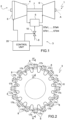
figure 1 is a simplified block diagram of a gas turbine engine in accordance with an embodiment of the present invention; -
figure 2 is a schematic front view of a combustor assembly of the gas turbine engine offigure 1 , made in accordance with an embodiment of the present invention; -
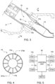
figure 3 is a cross-sectional lateral view of a combustor unit of the combustor assembly offigure 2 , cut along the line III-III offigure 2 ; -
figure 4 is a cross-sectional front view of a mixer of the combustor unitfigure 3 , cut along the line IV-IV offigure 3 ; -
figure 5 is a more detailed block diagram of component of the gas turbine engine offigure 1 ; and -
figure 6 are graphs showing quantities used in the gas turbine engine ofe 7figure 1 . - In
Figure 1 ,number 1 defines a gas turbine plant as a whole comprising agas turbine engine 2 and acontrol system 3. Thegas turbine engine 2, in turn, comprises acompressor 4, acombustor assembly 5 and an expansion section orturbine 6, all extending about an axis A. Thecompressor 4 and theturbine 6 share acommon rotor 7. - The
compressor 4 feeds thecombustor assembly 5 with an airflow drawn from outside. Air supply to thecompressor 4 is controllable by thecontrol system 3 by adjusting orientation ofinlet guide vanes 6 of thecompressor 4. - The
combustor assembly 5 mixes air from thecompressor 4 and fuel from a fuel supply line 9 to form a mixture for combustion. The fuel may be gaseous, for example natural gas or syngas, or liquid, for example gasoil. Thegas turbine engine 2 can be structured to use different types of fuel, both gaseous and liquid. Fuel supply is controllable by thecontrol system 3 through afuel valve system 10. - The
turbine 6 receives and expands a flow of hot gas from thecombustor assembly 5 to extract mechanical work, which is transferred to an external user, typically an electric generator, here not shown. - The
combustor assembly 5 is a two-stage or sequential can combustor and is provided with a plurality ofcombustor units 8 of a can type, which are circumferentially distributed about the axis A, as schematically illustrated infigure 2 . - One of the
combustor units 8 is shown in greater detail infigure 3 and comprises a first-stage combustor 12 and a second (or sequential)combustor 13, that define ahot gas path 14. Thecombustor unit 8 also comprises amixer 15, arranged along thehot gas path 14 between the first-stage combustor 12 and the second-stage combustor 13. Themixer 15 is configured to add dilution air and/or fuel to hot gas flowing from the first-stage combustor 12 in the hot gas path, in accordance with design preferences. - A
first temperature sensor 17a and asecond temperature sensor 17b are arranged in thehot gas path 14 at the mixer and are configured to sense respective temperatures of hot gas flowing around. In one embodiment, thefirst temperature sensor 17a and thesecond temperature sensor 17b may be thermocouples in use in contact with hot gas flowing through themixer 15 and are arranged at a same axial location at an outer boundary of thehot gas path 14 and are diametrally opposite to each other, respectively. Other arrangements of thefirst temperature sensor 17a and thesecond temperature sensor 17b may selected both for axial and angular positions, however, in accordance with design preferences. For example, thefirst temperature sensor 17a and thesecond temperature sensor 17b may be placed at any angular location on the periphery of a mixer exit plane at the same axial location. Specific angular locations may be selected based on configurations of the first-stage combustor 12 and of themixer 15. - The
first temperature sensors 17a provide respective first temperature measurements ST1a, ..., STNa and thesecond temperature sensors 17b provide respective second temperature measurements ST1b, ..., STNb, N being a number ofcombustors units 8. - The control system 3 (
figure 5 ) comprises acontrol unit 20 configured to determine a mixer exit temperature command METC for thegas turbine engine 1 based on the first temperature measurements ST1a, ..., STNa and the second temperature measurements ST1b, ..., STNb. Thecontrol unit 20 receives the first temperature measurements ST1a, ..., STNa and the second temperature measurements ST1b, ..., STNb and selects a first set Sa of intermediate first temperature measurements ST1a, ..., STNa and a second set Sb of intermediate second temperature measurements ST1b, ..., STNb and determines the mixer exit temperature command METC based on a combination of the selected first temperature measurements ST1a, ..., STNa and second temperature measurements ST1b, ..., STNb. Specifically, thecontrol unit 20 excludes the highest and the lowest first temperature measurements ST1a, ..., STNa and second temperature measurements ST1b, ..., STNb and includes the remaining intermediate first temperature measurements ST1a, ..., STNa in the first set Sa and the remaining intermediate second temperature measurements ST1b, ..., STNb in the second set Sb. More precisely, a first number NHa of highest first temperature measurements ST1a, ..., STNa and a second number NLa of lowest first temperature measurements ST1a, ..., STNa are excluded from the first set Sa (figure 6 ) and a third number NHb of highest second temperature measurements ST1b, ..., STNb and a fourth number NLb of lowest second temperature measurements ST1b, ..., STNb are excluded from the second set Sb (figure 7 ). - In one embodiment, for example, the third highest to the sixth highest first temperature measurements ST1a, ..., STNa and second temperature measurements ST1b, ..., STNb are included in the first group Sa and in the second group Sb, respectively; the two highest first temperature measurements ST1a, ..., STNa and second temperature measurements ST1b, ..., STNb and the lowest first temperature measurements ST1a, ..., STNa and second temperature measurements ST1b, ..., STNb. i.e. lower than the sixth highest, are excluded from the first group Sa and second group Sb.
- The first temperature measurements ST1a, ..., STNa of the first set Sa and the second temperature measurements ST1b, ..., STNb of the second set Sb need not be symmetrically selected with respect to the extreme first temperature measurements ST1a, ..., STNa and the second temperature measurements ST1b, ..., STNb, respectively. Also, the first group Sa and the second group Sb need not contain the same number of first temperature measurements ST1a, ..., STNa and second temperature measurements ST1b, ..., STNb and/or first temperature measurements ST1a, ..., STNa and second temperature measurements ST1b, ..., STNb of corresponding position when ordered form the highest to the lowest. In one embodiment, for example, the third highest to the sixth highest first temperature measurements ST1a, ..., STNa are included in the first group Sa and the fourth highest to the eight highest first temperature measurements ST1a, ..., STNa are included in the second group Sb.
- Then, the
control unit 20 calculates a first average temperature METa of the first temperature measurements ST1a, ..., STNa of the first set Sa; and a second average temperature METb of the second temperature measurements ST1b, ..., STNb obtained from the second set Sb. Finally, thecontrol unit 20 determines the mixer exit temperature command METC as a function of the first average temperature METa and of the second average temperature METb. In one embodiment, the mixer exit temperature command METC is defined as:
- The mixer exit temperature command METC is used by the
control system 3 to control thegas turbine engine 1, e.g. by determining a set-point of thegas turbine engine 1 and by controlling fuel and/or air supply to thecombustor units 8 of thecombustor assembly 3. - In one embodiment, the
control unit 20 is configured to allow modification of the criteria for selecting the first temperature measurements ST1a, ..., STNa and second temperature measurements ST1b, ..., STNb to be included in the first set Sa and second set Sb, respectively. For example, thecontrol unit 20 allows to modify the first number NHa of highest first temperature measurements ST1a, ..., STNa, the second number NLa of lowest first temperature measurements ST1a, ..., STNa, the third number NHb of highest second temperature measurements ST1b, ..., STNb and the fourth number NLb of lowest second temperature measurements ST1b, ..., STNb, thus modifying the composition of the first set Sa and of the second set Sb. - The process of identifying the highest and lowest temperature measurements may be iteratively carried out by the
control unit 5 during operation of thegas turbine engine 1 at every reading from thefirst temperature sensor 17a andsecond temperature sensor 17b or by averaging each first temperature measurement ST1a, ..., STNa and second temperature measurement ST1b, ..., STNb over a test interval. In the latter case, the composition of the first set Sa and of the second set Sb used to determine the first average temperature METa, the second average temperature METb and the mixer exit temperature command METC remains unchanged between test intervals. - It is finally apparent that changes and variations may be made to the gas turbine and method described and illustrated without departing from the scope of protection
of the accompanying claims.
Claims (15)
- A gas turbine engine comprising:a combustor assembly (5) having a plurality of combustor units (8) of a can type; anda control system (3) comprising a control unit (20);wherein each combustor unit (8) comprises:a first-stage combustor (12) and a second-stage combustor (13), that define a hot gas path (14);a mixer (15), arranged along the hot gas path (14) between the first-stage combustor (12) and the second-stage combustor (13);a first temperature sensor (17a) configured to provide respective first temperature measurements (ST1a, ..., STNa) of hot gas flowing through the mixer (15) of the respective combustor unit (8) at a respective first location; anda second temperature sensor (17b) configured to provide respective second temperature measurements (ST1b, ..., STNb) of hot gas flowing through the mixer (15) of the respective combustor unit (8) at a respective second location;wherein the control unit (20) is configured to calculate a first average temperature (METa) of a first set (Sa) of the first temperature measurements (ST1a, ..., STNa) and a second average temperature (METb) of a second set (Sb) of the second temperature measurements (ST1b, ..., STNb) and to determine a mixer exit temperature command (METC) as a function of the first average temperature (METa) and of the second average temperature (METb);and wherein highest first temperature measurements (ST1a, ..., STNa) and lowest first temperature measurements (ST1a, ..., STNa) are excluded from the first set (Sa) and highest second temperature measurements (ST1b, ..., STNb) and lowest second temperature measurements (ST1b, ..., STNb) are excluded from the second set (Sb).
- The gas turbine engine according to claim 1, wherein the control system (3) includes a control unit (20) configured to exclude a first number (NHa) of the highest first temperature measurements (ST1a, ..., STNa) and a second number (NLa) of the lowest first temperature measurements (ST1a, ..., STNa) from the first set (Sa) and to exclude a third number (NHb) of the highest second temperature measurements (ST1b, ..., STNb) and a fourth number (NLb) of the lowest second temperature measurements (ST1b, ..., STNb) from the second set (Sb).
- The gas turbine engine according to claim 2, wherein the first number (NHa) of the highest first temperature measurements (ST1a, ..., STNa) is equal to the third number (NHb) of the highest second temperature measurements (ST1b, ..., STNb) and the second number (NLa) of the lowest first temperature measurements (ST1a, ..., STNa) is equal to the fourth number (NLb) of the lowest second temperature measurements (ST1b, ..., STNb).
- The gas turbine engine according to any one of the preceding claims, wherein the control unit (20) is configured to determine the exit temperature command (METC) as:

- The gas turbine engine according to any one of the preceding claims, wherein the control system (3) is configured to control fuel and/or air supply to the combustor units (8) based on the exit temperature command (METC).
- The gas turbine engine according to any one of the preceding claims, wherein, in each combustor unit (8), the first location of the first temperature sensor (17a) and the second location of the second temperature sensor (17b) include a first axial location and a second axial location, respectively, and preferably the first axial location is equal to the second axial location.
- The gas turbine engine according to claim 6, wherein the first temperature sensor (17a) and the second temperature sensor (17b) are at an outlet of the mixer (15).
- The gas turbine engine according to any one of the preceding claims, wherein, in each combustor unit (8), the first location of the first temperature sensor (17a) and the second location of the second temperature sensor (17b) include a first angular location and a second angular location, respectively, and preferably the first angular location is diametrally opposite to the second angular location.
- The gas turbine engine according to any one of the preceding claims, wherein, in each combustor unit (8), the first temperature sensor (17a) and the second temperature sensor (17b) include respective thermocouples in use in contact with hot gas flowing through the mixer (15).
- A method of operating a gas turbine comprising a combustor assembly (5), having a plurality of combustor units (8) of a can type, wherein each combustor unit (8) comprises a first-stage combustor (12) and a second-stage combustor (13), that define a hot gas path (14), and a mixer (15), arranged along the hot gas path (14) between the first-stage combustor (12) and the second-stage combustor (13);
the method comprising:sensing first temperatures (ST1a, ..., STNa) of hot gas flowing through the mixer (15) of each combustor unit (8) at a respective first location (17a);sensing second temperatures (ST1b, ..., STNb) of hot gas flowing through the mixer (15) of each combustor unit (8) at a respective second location (17b);calculating a first average temperature (METa) of a first set (Sa) of the first temperature measurements (ST1a, ..., STNa) and a second average temperature (METb) of a second set (Sb) of the second temperature measurements (ST1b, ..., STNb); anddetermining a mixer exit temperature command (METC) as a function of the first average temperature (METa) and of the second average temperature (METb);wherein highest first temperature measurements (ST1a, ..., STNa) and lowest first temperature measurements (ST1a, ..., STNa) are excluded from the first set (Sa) and highest second temperature measurements (ST1b, ..., STNb) and lowest second temperature measurements (ST1b, ..., STNb) are excluded from the second set (Sb). - The method according to claim 10, comprising excluding a first number (NHa) of the highest first temperature measurements (ST1a, ..., STNa) and a second number (NLa) of the lowest first temperature measurements (ST1a, ..., STNa) from the first set (Sa) and excluding a third number (NHb) of the highest second temperature measurements (ST1b, ..., STNb) and a fourth number (NLb) of the lowest second temperature measurements (ST1b, ..., STNb) from the second set (Sb).
- The method according to claim 11, wherein the first number (NHa) of the highest first temperature measurements (ST1a, ..., STNa) is equal to the third number (NHb) of the highest second temperature measurements (ST1b, ..., STNb) and the second number (NLa) of the lowest first temperature measurements (ST1a, ..., STNa) is equal to the fourth number (NLb) of the lowest second temperature measurements (ST1b, ..., STNb).
- The method according to any one of claims 10 to 12, wherein the exit temperature command (METC) is determined as:

- The method according to any one of claims 10 to 13, wherein, in each combustor unit (8), the first location of the first temperature sensor (17a) and the second location of the second temperature sensor (17b) include a first axial location and a second axial location, respectively, at an outlet of the mixer (15) and preferably the first axial location is equal to the second axial location.
- The method according to claim 14, wherein, in each combustor unit (8), the first location of the first temperature sensor (17a) and the second location of the second temperature sensor (17b) include a first angular location and a second angular location, respectively, and preferably the first angular location is diametrally opposite to the second angular location.
Priority Applications (2)
| Application Number | Priority Date | Filing Date | Title |
|---|---|---|---|
| EP21218292.7A EP4206538B1 (en) | 2021-12-30 | 2021-12-30 | Gas turbine engine with selected combustor outlet temperature measurements and a method of operating a gas turbine engine |
| CN202211611896.8A CN116378824A (en) | 2021-12-30 | 2022-12-15 | Gas turbine engine and method of operating a gas turbine engine |
Applications Claiming Priority (1)
| Application Number | Priority Date | Filing Date | Title |
|---|---|---|---|
| EP21218292.7A EP4206538B1 (en) | 2021-12-30 | 2021-12-30 | Gas turbine engine with selected combustor outlet temperature measurements and a method of operating a gas turbine engine |
Publications (2)
| Publication Number | Publication Date |
|---|---|
| EP4206538A1 true EP4206538A1 (en) | 2023-07-05 |
| EP4206538B1 EP4206538B1 (en) | 2026-02-18 |
Family
ID=79164632
Family Applications (1)
| Application Number | Title | Priority Date | Filing Date |
|---|---|---|---|
| EP21218292.7A Active EP4206538B1 (en) | 2021-12-30 | 2021-12-30 | Gas turbine engine with selected combustor outlet temperature measurements and a method of operating a gas turbine engine |
Country Status (2)
| Country | Link |
|---|---|
| EP (1) | EP4206538B1 (en) |
| CN (1) | CN116378824A (en) |
Citations (4)
| Publication number | Priority date | Publication date | Assignee | Title |
|---|---|---|---|---|
| US4058975A (en) * | 1975-12-08 | 1977-11-22 | General Electric Company | Gas turbine temperature sensor validation apparatus and method |
| US20140144156A1 (en) * | 2012-11-29 | 2014-05-29 | Alstom Technology Ltd | Gas turbine temperature measurement |
| US20170138273A1 (en) * | 2015-11-13 | 2017-05-18 | Ansaldo Energia Switzerland AG | Method for controlling the operation of a gas turbine with an averaged turbine outlet temperature |
| US20170211487A1 (en) * | 2016-01-27 | 2017-07-27 | Ansaldo Energia Ip Uk Limited | Method for controlling a gas turbine operation with selected turbine outlet temperature measurements |
-
2021
- 2021-12-30 EP EP21218292.7A patent/EP4206538B1/en active Active
-
2022
- 2022-12-15 CN CN202211611896.8A patent/CN116378824A/en active Pending
Patent Citations (4)
| Publication number | Priority date | Publication date | Assignee | Title |
|---|---|---|---|---|
| US4058975A (en) * | 1975-12-08 | 1977-11-22 | General Electric Company | Gas turbine temperature sensor validation apparatus and method |
| US20140144156A1 (en) * | 2012-11-29 | 2014-05-29 | Alstom Technology Ltd | Gas turbine temperature measurement |
| US20170138273A1 (en) * | 2015-11-13 | 2017-05-18 | Ansaldo Energia Switzerland AG | Method for controlling the operation of a gas turbine with an averaged turbine outlet temperature |
| US20170211487A1 (en) * | 2016-01-27 | 2017-07-27 | Ansaldo Energia Ip Uk Limited | Method for controlling a gas turbine operation with selected turbine outlet temperature measurements |
Also Published As
| Publication number | Publication date |
|---|---|
| CN116378824A (en) | 2023-07-04 |
| EP4206538B1 (en) | 2026-02-18 |
Similar Documents
| Publication | Publication Date | Title |
|---|---|---|
| EP3069083B1 (en) | Intelligent control method with predictive emissions monitoring ability | |
| US20090222187A1 (en) | Gas turbine engine controls for minimizing combustion dynamics and emissions | |
| CN102996424B (en) | For simulating the system and method for gas-turbine compressor | |
| EP1387062B1 (en) | Method/system for mapping a combustor in a gas turbine engine | |
| US6778937B2 (en) | Method and system for identifying malfunctioning combustion chambers in a gas turbine | |
| US20110142602A1 (en) | Methods of determining variable element settings for a turbine engine | |
| US6003296A (en) | Flashback event monitoring (FEM) process | |
| EP2256301B1 (en) | Systems and methods for modifying the performance of a gas turbine | |
| US20180223743A1 (en) | Fuel control device, combustor, gas turbine, control method, and program | |
| JP2009047164A (en) | Method for mitigating undesirable gas turbine transient response using event-based operation | |
| EP4116561A1 (en) | Model based fuel-air ratio control | |
| US20220220905A1 (en) | Gas turbine engine fuel control system and method | |
| US20160069271A1 (en) | Bulk Flame Temperature Regulator for Dry Low Emission Engines | |
| EP3199781B1 (en) | A gas turbine and a corresponding method for controlling a gas turbine operation with seleceted turbine outlet temperature sensors | |
| EP4206538B1 (en) | Gas turbine engine with selected combustor outlet temperature measurements and a method of operating a gas turbine engine | |
| CN109210572B (en) | Second stage combustor for sequential combustor of gas turbine | |
| US20160356495A1 (en) | Method and system for operating a combustion device | |
| US10767569B2 (en) | Method for controlling the operation of a gas turbine with an averaged turbine outlet temperature | |
| US20140182297A1 (en) | Gas turbine and method of controlling a gas turbine at part-load condition | |
| EP3436180B1 (en) | Methods and systems for optimizing filter change interval | |
| EP4372210A1 (en) | Tuning engine parameter estimator using gas path analysis data | |
| Benvenuti | Innovative Gas Turbine Performance Diagnostics And Hot Parts Life Assessment Techniques. | |
| EP3543608A1 (en) | Burner for a gas turbine and method for operating the burner | |
| Cowell et al. | Field Qualification of an Improved DLE Gas Turbine Control Algorithm to Reduce Part Load Emissions | |
| EP4524386A1 (en) | Built-in test of actively controlled fuel nozzles |
Legal Events
| Date | Code | Title | Description |
|---|---|---|---|
| PUAI | Public reference made under article 153(3) epc to a published international application that has entered the european phase |
Free format text: ORIGINAL CODE: 0009012 |
|
| STAA | Information on the status of an ep patent application or granted ep patent |
Free format text: STATUS: THE APPLICATION HAS BEEN PUBLISHED |
|
| AK | Designated contracting states |
Kind code of ref document: A1 Designated state(s): AL AT BE BG CH CY CZ DE DK EE ES FI FR GB GR HR HU IE IS IT LI LT LU LV MC MK MT NL NO PL PT RO RS SE SI SK SM TR |
|
| STAA | Information on the status of an ep patent application or granted ep patent |
Free format text: STATUS: REQUEST FOR EXAMINATION WAS MADE |
|
| 17P | Request for examination filed |
Effective date: 20240103 |
|
| RBV | Designated contracting states (corrected) |
Designated state(s): AL AT BE BG CH CY CZ DE DK EE ES FI FR GB GR HR HU IE IS IT LI LT LU LV MC MK MT NL NO PL PT RO RS SE SI SK SM TR |
|
| P01 | Opt-out of the competence of the unified patent court (upc) registered |
Effective date: 20240430 |
|
| GRAP | Despatch of communication of intention to grant a patent |
Free format text: ORIGINAL CODE: EPIDOSNIGR1 |
|
| STAA | Information on the status of an ep patent application or granted ep patent |
Free format text: STATUS: GRANT OF PATENT IS INTENDED |
|
| INTG | Intention to grant announced |
Effective date: 20250915 |
|
| GRAS | Grant fee paid |
Free format text: ORIGINAL CODE: EPIDOSNIGR3 |
|
| GRAA | (expected) grant |
Free format text: ORIGINAL CODE: 0009210 |
|
| STAA | Information on the status of an ep patent application or granted ep patent |
Free format text: STATUS: THE PATENT HAS BEEN GRANTED |
|
| AK | Designated contracting states |
Kind code of ref document: B1 Designated state(s): AL AT BE BG CH CY CZ DE DK EE ES FI FR GB GR HR HU IE IS IT LI LT LU LV MC MK MT NL NO PL PT RO RS SE SI SK SM TR |
|
| REG | Reference to a national code |
Ref country code: CH Ref legal event code: F10 Free format text: ST27 STATUS EVENT CODE: U-0-0-F10-F00 (AS PROVIDED BY THE NATIONAL OFFICE) Effective date: 20260218 Ref country code: GB Ref legal event code: FG4D |
|
| REG | Reference to a national code |
Ref country code: DE Ref legal event code: R096 Ref document number: 602021048101 Country of ref document: DE |
|
| REG | Reference to a national code |
Ref country code: IE Ref legal event code: FG4D |
|
| REG | Reference to a national code |
Ref country code: NL Ref legal event code: MP Effective date: 20260218 |
|
| PG25 | Lapsed in a contracting state [announced via postgrant information from national office to epo] |
Ref country code: RS Free format text: LAPSE BECAUSE OF FAILURE TO SUBMIT A TRANSLATION OF THE DESCRIPTION OR TO PAY THE FEE WITHIN THE PRESCRIBED TIME-LIMIT Effective date: 20260518 |
|
| PG25 | Lapsed in a contracting state [announced via postgrant information from national office to epo] |
Ref country code: ES Free format text: LAPSE BECAUSE OF FAILURE TO SUBMIT A TRANSLATION OF THE DESCRIPTION OR TO PAY THE FEE WITHIN THE PRESCRIBED TIME-LIMIT Effective date: 20260218 |
|
| PG25 | Lapsed in a contracting state [announced via postgrant information from national office to epo] |
Ref country code: PL Free format text: LAPSE BECAUSE OF FAILURE TO SUBMIT A TRANSLATION OF THE DESCRIPTION OR TO PAY THE FEE WITHIN THE PRESCRIBED TIME-LIMIT Effective date: 20260218 |
|
| PG25 | Lapsed in a contracting state [announced via postgrant information from national office to epo] |
Ref country code: GR Free format text: LAPSE BECAUSE OF FAILURE TO SUBMIT A TRANSLATION OF THE DESCRIPTION OR TO PAY THE FEE WITHIN THE PRESCRIBED TIME-LIMIT Effective date: 20260519 |
|
| REG | Reference to a national code |
Ref country code: LT Ref legal event code: MG9D |
|
| PG25 | Lapsed in a contracting state [announced via postgrant information from national office to epo] |
Ref country code: LT Free format text: LAPSE BECAUSE OF FAILURE TO SUBMIT A TRANSLATION OF THE DESCRIPTION OR TO PAY THE FEE WITHIN THE PRESCRIBED TIME-LIMIT Effective date: 20260218 |
|
| PG25 | Lapsed in a contracting state [announced via postgrant information from national office to epo] |
Ref country code: NO Free format text: LAPSE BECAUSE OF FAILURE TO SUBMIT A TRANSLATION OF THE DESCRIPTION OR TO PAY THE FEE WITHIN THE PRESCRIBED TIME-LIMIT Effective date: 20260518 |
|
| PG25 | Lapsed in a contracting state [announced via postgrant information from national office to epo] |
Ref country code: FI Free format text: LAPSE BECAUSE OF FAILURE TO SUBMIT A TRANSLATION OF THE DESCRIPTION OR TO PAY THE FEE WITHIN THE PRESCRIBED TIME-LIMIT Effective date: 20260218 Ref country code: AT Free format text: LAPSE BECAUSE OF FAILURE TO SUBMIT A TRANSLATION OF THE DESCRIPTION OR TO PAY THE FEE WITHIN THE PRESCRIBED TIME-LIMIT Effective date: 20260218 Ref country code: SE Free format text: LAPSE BECAUSE OF FAILURE TO SUBMIT A TRANSLATION OF THE DESCRIPTION OR TO PAY THE FEE WITHIN THE PRESCRIBED TIME-LIMIT Effective date: 20260218 |
|
| REG | Reference to a national code |
Ref country code: AT Ref legal event code: MK05 Ref document number: 1888388 Country of ref document: AT Kind code of ref document: T Effective date: 20260218 |
|
| PG25 | Lapsed in a contracting state [announced via postgrant information from national office to epo] |
Ref country code: HR Free format text: LAPSE BECAUSE OF FAILURE TO SUBMIT A TRANSLATION OF THE DESCRIPTION OR TO PAY THE FEE WITHIN THE PRESCRIBED TIME-LIMIT Effective date: 20260218 |
|
| PG25 | Lapsed in a contracting state [announced via postgrant information from national office to epo] |
Ref country code: IS Free format text: LAPSE BECAUSE OF FAILURE TO SUBMIT A TRANSLATION OF THE DESCRIPTION OR TO PAY THE FEE WITHIN THE PRESCRIBED TIME-LIMIT Effective date: 20260618 Ref country code: PT Free format text: LAPSE BECAUSE OF FAILURE TO SUBMIT A TRANSLATION OF THE DESCRIPTION OR TO PAY THE FEE WITHIN THE PRESCRIBED TIME-LIMIT Effective date: 20260618 |
|
| PG25 | Lapsed in a contracting state [announced via postgrant information from national office to epo] |
Ref country code: NL Free format text: LAPSE BECAUSE OF FAILURE TO SUBMIT A TRANSLATION OF THE DESCRIPTION OR TO PAY THE FEE WITHIN THE PRESCRIBED TIME-LIMIT Effective date: 20260218 |
|
| PG25 | Lapsed in a contracting state [announced via postgrant information from national office to epo] |
Ref country code: LV Free format text: LAPSE BECAUSE OF FAILURE TO SUBMIT A TRANSLATION OF THE DESCRIPTION OR TO PAY THE FEE WITHIN THE PRESCRIBED TIME-LIMIT Effective date: 20260218 |
|
| PG25 | Lapsed in a contracting state [announced via postgrant information from national office to epo] |
Ref country code: BG Free format text: LAPSE BECAUSE OF FAILURE TO SUBMIT A TRANSLATION OF THE DESCRIPTION OR TO PAY THE FEE WITHIN THE PRESCRIBED TIME-LIMIT Effective date: 20260218 |