EP4206532A1 - Combustion chamber for a gas turbine engine - Google Patents
Combustion chamber for a gas turbine engine Download PDFInfo
- Publication number
- EP4206532A1 EP4206532A1 EP21425076.3A EP21425076A EP4206532A1 EP 4206532 A1 EP4206532 A1 EP 4206532A1 EP 21425076 A EP21425076 A EP 21425076A EP 4206532 A1 EP4206532 A1 EP 4206532A1
- Authority
- EP
- European Patent Office
- Prior art keywords
- cooling
- combustion chamber
- tile
- casing
- supporting devices
- Prior art date
- Legal status (The legal status is an assumption and is not a legal conclusion. Google has not performed a legal analysis and makes no representation as to the accuracy of the status listed.)
- Granted
Links
Images


Classifications
-
- F—MECHANICAL ENGINEERING; LIGHTING; HEATING; WEAPONS; BLASTING
- F23—COMBUSTION APPARATUS; COMBUSTION PROCESSES
- F23R—GENERATING COMBUSTION PRODUCTS OF HIGH PRESSURE OR HIGH VELOCITY, e.g. GAS-TURBINE COMBUSTION CHAMBERS
- F23R3/00—Continuous combustion chambers using liquid or gaseous fuel
-
- F—MECHANICAL ENGINEERING; LIGHTING; HEATING; WEAPONS; BLASTING
- F23—COMBUSTION APPARATUS; COMBUSTION PROCESSES
- F23R—GENERATING COMBUSTION PRODUCTS OF HIGH PRESSURE OR HIGH VELOCITY, e.g. GAS-TURBINE COMBUSTION CHAMBERS
- F23R3/00—Continuous combustion chambers using liquid or gaseous fuel
- F23R3/007—Continuous combustion chambers using liquid or gaseous fuel constructed mainly of ceramic components
-
- F—MECHANICAL ENGINEERING; LIGHTING; HEATING; WEAPONS; BLASTING
- F23—COMBUSTION APPARATUS; COMBUSTION PROCESSES
- F23R—GENERATING COMBUSTION PRODUCTS OF HIGH PRESSURE OR HIGH VELOCITY, e.g. GAS-TURBINE COMBUSTION CHAMBERS
- F23R3/00—Continuous combustion chambers using liquid or gaseous fuel
- F23R3/42—Continuous combustion chambers using liquid or gaseous fuel characterised by the arrangement or form of the flame tubes or combustion chambers
- F23R3/60—Support structures; Attaching or mounting means
-
- F—MECHANICAL ENGINEERING; LIGHTING; HEATING; WEAPONS; BLASTING
- F23—COMBUSTION APPARATUS; COMBUSTION PROCESSES
- F23R—GENERATING COMBUSTION PRODUCTS OF HIGH PRESSURE OR HIGH VELOCITY, e.g. GAS-TURBINE COMBUSTION CHAMBERS
- F23R2900/00—Special features of, or arrangements for continuous combustion chambers; Combustion processes therefor
- F23R2900/00017—Assembling combustion chamber liners or subparts
-
- F—MECHANICAL ENGINEERING; LIGHTING; HEATING; WEAPONS; BLASTING
- F23—COMBUSTION APPARATUS; COMBUSTION PROCESSES
- F23R—GENERATING COMBUSTION PRODUCTS OF HIGH PRESSURE OR HIGH VELOCITY, e.g. GAS-TURBINE COMBUSTION CHAMBERS
- F23R2900/00—Special features of, or arrangements for continuous combustion chambers; Combustion processes therefor
- F23R2900/03044—Impingement cooled combustion chamber walls or subassemblies
-
- F—MECHANICAL ENGINEERING; LIGHTING; HEATING; WEAPONS; BLASTING
- F23—COMBUSTION APPARATUS; COMBUSTION PROCESSES
- F23R—GENERATING COMBUSTION PRODUCTS OF HIGH PRESSURE OR HIGH VELOCITY, e.g. GAS-TURBINE COMBUSTION CHAMBERS
- F23R2900/00—Special features of, or arrangements for continuous combustion chambers; Combustion processes therefor
- F23R2900/03045—Convection cooled combustion chamber walls provided with turbolators or means for creating turbulences to increase cooling
Definitions
- the present invention relates to a gas turbine engine with selected outlet temperature measurements and to a method of operating a gas turbine engine.
- thermoinsulating shield generally consists of a plurality of tiles of ceramic material arranged in contiguous rows on the inner surface of the casing of the combustion chamber, so as to define a substantially continuous surface.
- the tiles are arranged to form circles around the (horizontal) rotor axis.
- the rows may still form circles, yet around vertical axes, or vertical columns.
- a supporting device comprises a plate, configured to engage a corresponding groove in the casing of the combustion chamber, and a hooked head, protruding outside the groove and configured to be coupled to an edge of the tile.
- the hooked head has a first portion extending orthogonally from the plate and a second portion parallel to the plate.
- the edges of the tiles are normally provided with seats configured to receive the second portion of the hooked head.
- the supporting devices are elastic and, are loaded to ensure stable mounting, once the tiles are placed in their seats.
- the supporting devices may be subject to sever thermal stress, because of thermal conduction with the ceramic material ingestion of hot gas that may penetrate between adjacent tiles of the same row or of contiguous rows. In fact, gaps between adjacent tiles are not sealed and hot gas may reach the supporting devices.
- high temperature and mechanical stress due to vibrations may induce creeping and cause the elastic material forming the supporting devices to exceed the fatigue threshold.
- a combustion chamber for a gas turbine engine comprising:
- the configuration of the supporting device allows introduction of the first cooling jets directly into the channel so that the hooked head may be reached by impingement flow.
- the first cooling holes and the second cooling holes provide protection of the supporting devices, specifically directed to the plates (first portions) and to the hooking heads (second portions), which are mostly exposed to hot gas.
- An impingement scheme is used, thus taking advantage from the associated efficiency.
- the risk of creeping and of exceeding the fatigue threshold of the material forming the supporting devices is avoided or at least substantially mitigated.
- the channel may be defined in practice in the supporting device and the respective tile only delimits one side. No special shape of the coupling sides of the tiles is required and, in particular, there is no need to create recesses in the tiles to allow passage of air.
- the combustion chamber comprises a plurality of second cooling holes configured to direct respective second cooling jets against the second portion of the supporting device.
- the combustion chamber comprises a plurality of first cooling holes configured to direct respective first cooling jets against respective portions of the first portion of the supporting device.
- the first cooling holes associated with supporting devices of adjacent tiles of the same row of tiles are configured to deliver the respective first cooling jets so that the respective first cooling jets flow along the first portions of the respective supporting devices and interact with each other at a gap between the respective supporting devices, thereby sealing the gap.
- Cooling air supplied by the first cooling holes flows along the plates toward the spaces between adjacent tiles. Opposite flows interact in such space and help seal gaps, further reducing the risk of hot gas ingestion.
- the second cooling holes are aligned with the through openings and the channels of the respective supporting devices, whereby the second cooling jets are directed into the through openings and the channels of the respective supporting devices.
- the second portion of each supporting device is T-shaped and has a stem projecting perpendicularly from the respective first portion and a hook, extending transversely to the stem and wherein the second cooling jets are directed against the hooks of the respective supporting devices through the respective channels.
- the spacers are L-shaped and have respective first legs, parallel to the stem and defining the channel, and respective second legs, parallel to the hook and extending in opposite directions from the respective first legs.
- each supporting device in each supporting device, the respective channel is split into two opposite branches each defined between the hook and the second leg of a respective one of the spacers, the branches discharging on opposite sides of the hook.
- the coupling structures comprise continuous ribs extending along respective coupling sides of the tiles.
- the ribs have respective flat faces resting against the second portions of the respective supporting devices.
- the casing has a plurality of sealing holes in the grooves at the separation regions and the sealing holes are configured to direct respective sealing jets of cooling air through the separation regions to impinge on the central portions of respective tiles, thereby sealing a space between the respective tile and the casing.
- sealing holes avoids ingestion of hot gas in the space between the tiles and the casing of the combustion chamber, thus allowing additional protection against high temperature.
- the sealing holes are also configured to cause cooling of the central portions of the tiles by impingement of the respective sealing jets. In addition to sealing action, therefore, also in this case an impingement cooling scheme is exploited, which is particularly effective.
- the sealing holes associated with each tile are organized in rows extending longitudinally in the respective grooves.
- the casing has a plurality of parallel rows of sealing holes at each separation region.
- the arrangement of the sealing holes may be flexibly selected in accordance with design preferences to obtain the desired effect, also in consideration of the specific position in the combustion chamber.
- the number, size and location of the sealing holes may vary from a groove to another in order to optimize protection of the supporting elements and consumption of cooling air.
- the sealing holes are configured to direct the respective sealing jets perpendicularly to the tiles.
- the sealing holes are also configured to cause cooling of the central portions of the tiles by impingement of the respective sealing jets.
- an impingement cooling scheme is exploited, which is particularly effective.
- FIGS 1-3 illustrate a combustion chamber 1 of a gas turbine engine, not shown in its entirety, in accordance with a non-limiting embodiment of the present invention.
- the combustion chamber is of the annular type. It is however understood that the invention may be exploited also in combustion chambers of different type, such as silo combustion chambers.
- the combustion chamber 1 comprises an annular casing 2 extending around an axis R and is provided with a heat shield 3 that covers internally the casing 2.
- the heat shield 3 comprises a plurality of thermoinsulating tiles 4 of a ceramic material, fastened to the casein arranged in adjacent rows, along circumferences, around the axis R of the combustion chamber 1.
- the tiles 4 are fastened to the casing 2 by respective supporting devices 5.
- the supporting devices 5 engage circumferential grooves 7, which are formed on an inner face of the casing 2 around the axis R and are configured to receive the supporting devices 5 of a respective row of tiles 4 at respective locations.
- the tiles 4 have a quadrangular shape and have, respective ribs 8 extending along opposite coupling sides for coupling with the supporting devices 5.
- the ribs 8 define coupling structures of the tiles 4 and have flat and continuous faces resting against the respective supporting devices 5.
- Each tile 4 is fastened by two pairs of respective supporting devices 5.
- Each pair of supporting devices 5 engage a respective one of two adjacent grooves 7 and the supporting devices 5 of each pair are coupled to opposite coupling sides of the tile 4.
- the tile 4 is placed in its seat and the supporting devices 5 for the other coupling side of the tile 4 are fitted.
- the supporting devices 5 for the other coupling side of the tile 4 are not secured to the casing to accommodate thermal expansion.
- the supporting device 5 has a first portion in the form of a plate 10 configured to engage a respective groove 7 and a second portion in the form of a hooked head 12 configured to couple to the rib 8 on one of the coupling sides of a respective tile 4.
- the hooked head 12 of the supporting device 5 is T-shaped and has a stem 12a projecting perpendicularly from the respective plate 10 and a hook 12b, extending transversely to the stem 12a. Spacers 15 are provided on a face 12c of the hooked head 12 oriented toward the respective tile 4.
- the spacers 15 are interposed between the face 12c of the hooked head 12 and the respective tile 4 and a channel 16 is defined between the face 12c of the hooked head 12, the spacers 15 and the tile 4.
- the channel 16 is also aligned with a through opening 17 formed at a connection 14 of the plate 10 and the hooked head 12.
- the spacers 15 are L-shaped and have respective first legs 15a, parallel to the stem 12a and defining the channel 16, and respective second legs 15b, parallel to the hook 12b and extending in opposite directions from the respective first legs 15a.
- the channel 16 is split into two opposite branches 16a, each defined between the hook 12b and the second leg 15b of a respective one of the spacers 15.
- the branches are open and discharge on opposite sides of the hook 12b.
- the plates 10 of each pair of supporting devices 5, which are coupled to the same tile 4 and engage the same groove 7, are separated from each other by a respective separation region 19 at a central portion of the respective tile 4.
- the casing 2 has a plurality of sealing holes 20 in the grooves 7 at the separation regions 19.
- the sealing holes 20 are configured to create and direct respective sealing jets 21 of cooling air through the separation regions 19 perpendicularly to the tiles 4.
- the sealing jets 21 are mixed in a cross or transverse flow thereby sealing the separation region 19 and, in general, a space between the respective tile 4 and the casing 2. More precisely, the sealing holes 20 are configured to direct the respective sealing jets 21 perpendicularly to the tiles 4.
- the sealing holes 20 associated with each tile 4 are organized in rows extending longitudinally in the respective grooves 7.
- the casing 2 may have one or more parallel rows of sealing holes 20 at each separation region (two in the embodiment of figure 4 ).
- the casing 2 has at least one head cooling hole 23, configured to direct a head cooling jet 25 of cooling air against the hooking head 12 and at least one plate cooling hole 27 configured to direct a plate cooling jet 28 of cooling air against the plate 10 of the supporting device.
- the head cooling holes 23 are aligned with the through openings 17 and the channels 16 of the respective supporting devices 5. Thus, the head cooling jets 25 delivered by the head cooling holes 23 are directed against the hooks of 12b the respective supporting devices 5 through the respective through openings 17 and channels 16.
- the plate cooling holes 27 are configured to deliver the respective plate cooling jets 28 so that the respective plate cooling jets 28 impinge on the plates 10 of the respective supporting devices 5 and flow along the plates 10 toward the respective hooked heads 12, thus also providing a convective cooling effect. Moreover, plate cooling jets 28 delivered by the plate cooling holes 27 associated with supporting devices of adjacent tiles 4 of the same row of tiles 4 interact with each other at a gap 30 between the respective supporting devices 5. The gap 30 is therefore sealed by the interacting plate cooling jets 28.
- one head cooling hole 23 and one plate cooling holes 27 are provided for each supporting device 5.
- Other configurations are possible, however, as illustrated e.g. in figures 8 and 9 .
- the casing 2 has one head cooling hole 23 as already described and a plurality of plate cooling holes 27, all aligned in a single row.
- the casing 2 has a plurality of head cooling holes 23 (four), arranged in a matrix and directing the respective head cooling jets 25 against the hook 12b of the respective supporting device 5, and a plurality of plate cooling holes 27, arranged in parallel rows.
- the number, size and location of the sealing holes 20, of the head cooling holes 23 and of the plate cooling holes 27 may be selected in accordance with design preferences and may be different as required in distinct grooves 7.
Landscapes
- Engineering & Computer Science (AREA)
- Chemical & Material Sciences (AREA)
- Combustion & Propulsion (AREA)
- Mechanical Engineering (AREA)
- General Engineering & Computer Science (AREA)
- Ceramic Engineering (AREA)
- Turbine Rotor Nozzle Sealing (AREA)
- Cylinder Crankcases Of Internal Combustion Engines (AREA)
Abstract
Description
- The present invention relates to a gas turbine engine with selected outlet temperature measurements and to a method of operating a gas turbine engine.
- As known, the combustion chamber of a gas turbine engines need be internally protected by a thermoinsulating shield of ceramic material, due to the high temperatures reached during the operation. The thermoinsulating shield generally consists of a plurality of tiles of ceramic material arranged in contiguous rows on the inner surface of the casing of the combustion chamber, so as to define a substantially continuous surface. In annular combustion chambers, for example, the tiles are arranged to form circles around the (horizontal) rotor axis. In combustion chambers of the silo type, the rows may still form circles, yet around vertical axes, or vertical columns.
- Normally, the tiles are fastened to the casing by supporting devices which couple to seats on the sides of the tiles themselves. More precisely, a supporting device comprises a plate, configured to engage a corresponding groove in the casing of the combustion chamber, and a hooked head, protruding outside the groove and configured to be coupled to an edge of the tile. The hooked head has a first portion extending orthogonally from the plate and a second portion parallel to the plate. The edges of the tiles are normally provided with seats configured to receive the second portion of the hooked head. The supporting devices are elastic and, are loaded to ensure stable mounting, once the tiles are placed in their seats.
- The supporting devices may be subject to sever thermal stress, because of thermal conduction with the ceramic material ingestion of hot gas that may penetrate between adjacent tiles of the same row or of contiguous rows. In fact, gaps between adjacent tiles are not sealed and hot gas may reach the supporting devices.
- In particular, high temperature and mechanical stress due to vibrations may induce creeping and cause the elastic material forming the supporting devices to exceed the fatigue threshold.
- It is thus an object of the present invention to provide combustion chamber that allow to overcome or at least attenuate the above described limitations.
- According to the present invention, there is provided a combustion chamber for a gas turbine engine comprising:
- a casing; and
- a heat shield comprising a plurality of ceramic tiles arranged in rows and removably fastened to the casing by respective supporting devices;
- wherein the casing has grooves configured to receive the supporting devices of a respective row of tiles at respective locations;
- wherein each tile has opposite coupling sides with respective coupling structures;
- wherein each supporting device has a respective first portion in the form of a plate configured to engage a respective groove and a respective second portion in the form of a hooked head configured to couple to the coupling structure on one of the coupling sides of a respective tile;
- wherein each tile is fastened to the casing by at least one pair of supporting devices, which engage the same groove and are coupled to opposite coupling sides of the tile;
- wherein the first portions of the supporting devices of each tile are separated from each other by a respective separation region at a central portion of the respective tile;
- wherein, for each supporting device, the casing has at least one first cooling hole at least one first cooling hole in the respective groove, the at least one first cooling hole being configured to direct a first cooling jet of cooling air against the second portion of the supporting device and the at least one first cooling hole being configured to direct a first cooling jet of cooling air against the first portion of the supporting device;
- wherein each supporting device has a through opening at a connection of the first portion and the second portion and spacers on a face of the respective second portion, wherein the spacers are interposed between the face and the respective tile and wherein a channel aligned with the through opening is defined between the face, the spacers and the tile.
- The configuration of the supporting device allows introduction of the first cooling jets directly into the channel so that the hooked head may be reached by impingement flow. The first cooling holes and the second cooling holes provide protection of the supporting devices, specifically directed to the plates (first portions) and to the hooking heads (second portions), which are mostly exposed to hot gas. An impingement scheme is used, thus taking advantage from the associated efficiency. The risk of creeping and of exceeding the fatigue threshold of the material forming the supporting devices is avoided or at least substantially mitigated. Due to the provision of the spacers, moreover, the channel may be defined in practice in the supporting device and the respective tile only delimits one side. No special shape of the coupling sides of the tiles is required and, in particular, there is no need to create recesses in the tiles to allow passage of air.
- According to an aspect of the invention, the combustion chamber comprises a plurality of second cooling holes configured to direct respective second cooling jets against the second portion of the supporting device.
- According to an aspect of the invention, the combustion chamber comprises a plurality of first cooling holes configured to direct respective first cooling jets against respective portions of the first portion of the supporting device.
- According to an aspect of the invention, the first cooling holes associated with supporting devices of adjacent tiles of the same row of tiles are configured to deliver the respective first cooling jets so that the respective first cooling jets flow along the first portions of the respective supporting devices and interact with each other at a gap between the respective supporting devices, thereby sealing the gap.
- Cooling air supplied by the first cooling holes flows along the plates toward the spaces between adjacent tiles. Opposite flows interact in such space and help seal gaps, further reducing the risk of hot gas ingestion.
- According to an aspect of the invention, the second cooling holes are aligned with the through openings and the channels of the respective supporting devices, whereby the second cooling jets are directed into the through openings and the channels of the respective supporting devices.
- According to an aspect of the invention, the second portion of each supporting device is T-shaped and has a stem projecting perpendicularly from the respective first portion and a hook, extending transversely to the stem and wherein the second cooling jets are directed against the hooks of the respective supporting devices through the respective channels.
- According to an aspect of the invention, wherein, in each supporting device, the spacers are L-shaped and have respective first legs, parallel to the stem and defining the channel, and respective second legs, parallel to the hook and extending in opposite directions from the respective first legs.
- According to an aspect of the invention, in each supporting device, the respective channel is split into two opposite branches each defined between the hook and the second leg of a respective one of the spacers, the branches discharging on opposite sides of the hook.
- According to an aspect of the invention, wherein the coupling structures comprise continuous ribs extending along respective coupling sides of the tiles.
- According to an aspect of the invention, the ribs have respective flat faces resting against the second portions of the respective supporting devices.
- According to an aspect of the invention, the casing has a plurality of sealing holes in the grooves at the separation regions and the sealing holes are configured to direct respective sealing jets of cooling air through the separation regions to impinge on the central portions of respective tiles, thereby sealing a space between the respective tile and the casing.
- The sealing action provided by the sealing holes avoids ingestion of hot gas in the space between the tiles and the casing of the combustion chamber, thus allowing additional protection against high temperature. The sealing holes are also configured to cause cooling of the central portions of the tiles by impingement of the respective sealing jets. In addition to sealing action, therefore, also in this case an impingement cooling scheme is exploited, which is particularly effective.
- According to an aspect of the invention, the sealing holes associated with each tile are organized in rows extending longitudinally in the respective grooves.
- According to an aspect of the invention, the casing has a plurality of parallel rows of sealing holes at each separation region.
- The arrangement of the sealing holes may be flexibly selected in accordance with design preferences to obtain the desired effect, also in consideration of the specific position in the combustion chamber. For example, the number, size and location of the sealing holes may vary from a groove to another in order to optimize protection of the supporting elements and consumption of cooling air.
- According to an aspect of the invention, the sealing holes are configured to direct the respective sealing jets perpendicularly to the tiles.
- The sealing holes are also configured to cause cooling of the central portions of the tiles by impingement of the respective sealing jets. In addition to sealing action, therefore, an impingement cooling scheme is exploited, which is particularly effective.
- The present invention will now be described with reference to the accompanying drawings, which illustrate some non-limitative embodiments thereof, in which:
-
figure 1 is a side view, cut along a vertical axial plane, of a combustion chamber for a gas turbine engine in accordance with an embodiment of the present invention; -
figure 2 is a rear view of the combustion chamber offigure 1 , cut along the plane A-A offigure 1 , with parts removed for clarity; -
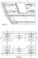
figure 3 is a perspective view of an enlarged detail of the combustion chamber offigure 1 , partly exploded and with parts removed for clarity; -
figure 4 is a top plan view of a portion of the combustion chamber offigure 1 ; -
figure 5 is a front perspective view of a supporting device for thermoinsulating tiles of the combustion chamber offigure 1 ; -
figure 6 shows a first enlarged detail of the combustion chamber offigure 1 , cut along the plane B-B offigure 4 ; -
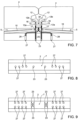
figure 7 shows a second enlarged detail of the combustion chamber offigure 1 , cut along the plane B-B offigure 4 ; -
figure 8 is a simplified top plan view with parts removed for clarity of a detail of a combustion chamber in accordance with a different embodiment of the present invention; and -
figure 9 is a simplified top plan view with parts removed for clarity of a detail of a combustion chamber in accordance with another embodiment of the present invention. -
Figures 1-3 illustrate acombustion chamber 1 of a gas turbine engine, not shown in its entirety, in accordance with a non-limiting embodiment of the present invention. In the embodiment herein described, in particular, the combustion chamber is of the annular type. It is however understood that the invention may be exploited also in combustion chambers of different type, such as silo combustion chambers. - The
combustion chamber 1 comprises anannular casing 2 extending around an axis R and is provided with a heat shield 3 that covers internally thecasing 2. The heat shield 3 comprises a plurality ofthermoinsulating tiles 4 of a ceramic material, fastened to the casein arranged in adjacent rows, along circumferences, around the axis R of thecombustion chamber 1. - With reference to
figures 3 and 4 , thetiles 4 are fastened to thecasing 2 by respective supportingdevices 5. The supportingdevices 5 engagecircumferential grooves 7, which are formed on an inner face of thecasing 2 around the axis R and are configured to receive the supportingdevices 5 of a respective row oftiles 4 at respective locations. More in detail, thetiles 4 have a quadrangular shape and have,respective ribs 8 extending along opposite coupling sides for coupling with the supportingdevices 5. Theribs 8 define coupling structures of thetiles 4 and have flat and continuous faces resting against the respective supportingdevices 5. Eachtile 4 is fastened by two pairs of respective supportingdevices 5. Each pair of supportingdevices 5 engage a respective one of twoadjacent grooves 7 and the supportingdevices 5 of each pair are coupled to opposite coupling sides of thetile 4. - Once the supporting
devices 5 for a coupling side of atile 4 have been slidingly inserted inadjacent grooves 7 and secured to thecasing 2 byscrews 9, thetile 4 is placed in its seat and the supportingdevices 5 for the other coupling side of thetile 4 are fitted. Preferably, the supportingdevices 5 for the other coupling side of thetile 4 are not secured to the casing to accommodate thermal expansion. - One of the supporting
devices 5 is illustrated with more detail infigure 5 . The supportingdevice 5 has a first portion in the form of aplate 10 configured to engage arespective groove 7 and a second portion in the form of a hookedhead 12 configured to couple to therib 8 on one of the coupling sides of arespective tile 4. The hookedhead 12 of the supportingdevice 5 is T-shaped and has astem 12a projecting perpendicularly from therespective plate 10 and ahook 12b, extending transversely to thestem 12a.Spacers 15 are provided on aface 12c of the hookedhead 12 oriented toward therespective tile 4. In use, thespacers 15 are interposed between theface 12c of the hookedhead 12 and therespective tile 4 and achannel 16 is defined between theface 12c of the hookedhead 12, thespacers 15 and thetile 4. Thechannel 16 is also aligned with a throughopening 17 formed at aconnection 14 of theplate 10 and the hookedhead 12. Thespacers 15 are L-shaped and have respectivefirst legs 15a, parallel to thestem 12a and defining thechannel 16, and respectivesecond legs 15b, parallel to thehook 12b and extending in opposite directions from the respectivefirst legs 15a. Thus, thechannel 16 is split into twoopposite branches 16a, each defined between thehook 12b and thesecond leg 15b of a respective one of thespacers 15. The branches are open and discharge on opposite sides of thehook 12b. - With reference again to
figure 3 and 4 , theplates 10 of each pair of supportingdevices 5, which are coupled to thesame tile 4 and engage thesame groove 7, are separated from each other by arespective separation region 19 at a central portion of therespective tile 4. - The
casing 2 has a plurality of sealingholes 20 in thegrooves 7 at theseparation regions 19. The sealing holes 20 are configured to create and directrespective sealing jets 21 of cooling air through theseparation regions 19 perpendicularly to thetiles 4. The sealingjets 21 are mixed in a cross or transverse flow thereby sealing theseparation region 19 and, in general, a space between therespective tile 4 and thecasing 2. More precisely, the sealing holes 20 are configured to direct therespective sealing jets 21 perpendicularly to thetiles 4. The sealing holes 20 associated with eachtile 4 are organized in rows extending longitudinally in therespective grooves 7. Thecasing 2 may have one or more parallel rows of sealingholes 20 at each separation region (two in the embodiment offigure 4 ). - For each supporting device, the
casing 2 has at least onehead cooling hole 23, configured to direct ahead cooling jet 25 of cooling air against the hookinghead 12 and at least oneplate cooling hole 27 configured to direct aplate cooling jet 28 of cooling air against theplate 10 of the supporting device. - The head cooling holes 23 are aligned with the through
openings 17 and thechannels 16 of the respective supportingdevices 5. Thus, thehead cooling jets 25 delivered by the head cooling holes 23 are directed against the hooks of 12b the respective supportingdevices 5 through the respective throughopenings 17 andchannels 16. - The plate cooling holes 27 are configured to deliver the respective
plate cooling jets 28 so that the respectiveplate cooling jets 28 impinge on theplates 10 of the respective supportingdevices 5 and flow along theplates 10 toward the respectivehooked heads 12, thus also providing a convective cooling effect. Moreover,plate cooling jets 28 delivered by the plate cooling holes 27 associated with supporting devices ofadjacent tiles 4 of the same row oftiles 4 interact with each other at agap 30 between the respective supportingdevices 5. Thegap 30 is therefore sealed by the interactingplate cooling jets 28. - As illustrated in
figures 4 and7 , onehead cooling hole 23 and one plate cooling holes 27 are provided for each supportingdevice 5. Other configurations are possible, however, as illustrated e.g. infigures 8 and 9 . - In the embodiment of
figure 8 , thecasing 2 has onehead cooling hole 23 as already described and a plurality of plate cooling holes 27, all aligned in a single row. - In the embodiment of
figure 9 , thecasing 2 has a plurality of head cooling holes 23 (four), arranged in a matrix and directing the respectivehead cooling jets 25 against thehook 12b of the respective supportingdevice 5, and a plurality of plate cooling holes 27, arranged in parallel rows. - In general, the number, size and location of the sealing holes 20, of the head cooling holes 23 and of the plate cooling holes 27 may be selected in accordance with design preferences and may be different as required in
distinct grooves 7. - It is finally apparent that changes and variations may be made to the combustion chamber described and illustrated without departing from the scope of protection of the accompanying claims.
Claims (14)
- A combustion chamber for a gas turbine engine comprising:a casing (2); anda heat shield (3) comprising a plurality of ceramic tiles (4) arranged in rows and removably fastened to the casing (2) by respective supporting devices (5);wherein the casing (2) has grooves (7) configured to receive the supporting devices (5) of a respective row of tiles (4) at respective locations;wherein each tile (4) has opposite coupling sides with respective coupling structures (8);wherein each supporting device (5) has a respective first portion (10) in the form of a plate configured to engage a respective groove (7) and a respective second portion (12) in the form of a hooked head configured to couple to the coupling structure (8) on one of the coupling sides of a respective tile (4);wherein each tile (4) is fastened to the casing (2) by at least one pair of supporting devices (5), which engage the same groove (7) and are coupled to opposite coupling sides of the tile (4);wherein, for each supporting device (5), the casing (2) has at least one first cooling hole (27) at least one second cooling hole (23) in the respective groove (7), the at least one first cooling hole (27) being configured to direct a first cooling jet (28) of cooling air against the first portion (10) of the supporting device (5) and the at least one second cooling hole (23) being configured to direct a second cooling jet (25) of cooling air against the second portion (12) of the supporting device (5);wherein each supporting device (5) has a through opening at a connection of the first portion (10) and the second portion (12) and spacers (15) on a face (12c) of the respective second portion (12), wherein the spacers (15) are interposed between the face (12c) and the respective tile (4) and wherein a channel (16) aligned with the through opening (17) is defined between the face (12c), the spacers (15) and the tile (4).
- The combustion chamber according to claim 1, comprising a plurality of second cooling holes (23) configured to direct respective second cooling jets (25) against the second portion (12) of the supporting device (5) .
- The combustion chamber according to claim 1 or 2, comprising a plurality of first cooling holes (27) configured to direct respective first cooling jets (28) against respective portions of the first portion (10) of the supporting device (5).
- The combustion chamber according to claim 3, wherein the first cooling holes (27) associated with supporting devices (5) of adjacent tiles (4) of the same row of tiles (4) are configured to deliver the respective first cooling jets (28) so that the respective first cooling jets (28) impinge on and flow along the first portions (10) of the respective supporting devices (5) and interact with each other at a gap (30) between the respective supporting devices (5), thereby sealing the gap (30).
- The combustion chamber according to any one of the preceding claims, wherein the second cooling holes (23) are aligned with the through openings (17) and the channels (16) of the respective supporting devices (5), whereby the second cooling jets (25) are directed into the through openings (17) and the channels (16) of the respective supporting devices (5).
- The combustion chamber according to claim 5, wherein the second portion (12) of each supporting device (5) is T-shaped and has a stem (12a) projecting perpendicularly from the respective first portion (10) and a hook (12b), extending transversely to the stem (12a) and wherein the second cooling jets (25) are directed against the hooks of (12b) the respective supporting devices (5) through the respective channels (16).
- The combustion chamber according to claim 6, wherein, in each supporting device (5), the spacers (15) are L-shaped and have respective first legs (15a), parallel to the stem (12a) and defining the channel (16) between each other, and respective second legs (12b), parallel to the hook (12b) and extending in opposite directions from the respective first legs (15a).
- The combustion chamber according to claim 7, wherein, in each supporting device (5), the respective channel (16) is split into two opposite branches (16a) each defined between the hook (12b) and the second leg (15b) of a respective one of the spacers (15), the branches (16a) discharging on opposite sides of the hook (12b).
- The combustion chamber according to any one of the preceding claims, wherein the coupling structures (8) comprise continuous ribs extending along respective coupling sides of the tiles (4).
- The combustion chamber according to claim 9, wherein the ribs have respective flat faces (12c) resting against the second portions (12) of the respective supporting devices (5) .
- The combustion chamber according to any one of the preceding claims, wherein the first portions (10) of the supporting devices (5) of each tile (4) are separated from each other by a respective separation region at a central portion of the respective tile (4);
and wherein the casing (2) has a plurality of sealing holes (20) in the grooves (7) at the separation regions and the sealing holes (20) are configured to direct respective sealing jets (21) of cooling air through the separation regions to impinge on the central portions of respective tiles (4), thereby sealing a space between the respective tile (4) and the casing (2). - The combustion chamber according to claim 11, wherein the sealing holes (20) associated with each tile (4) are organized in rows extending longitudinally in the respective grooves (7).
- The combustion chamber according to claim 12, wherein the casing (2) has a plurality of parallel rows of sealing holes (20) at each separation region.
- The combustion chamber according to any one of claims 11 to 13, wherein the sealing holes (20) are configured to direct the respective sealing jets (21) perpendicularly to the tiles (4).
Priority Applications (2)
| Application Number | Priority Date | Filing Date | Title |
|---|---|---|---|
| EP21425076.3A EP4206532B1 (en) | 2021-12-30 | 2021-12-30 | Combustion chamber for a gas turbine engine |
| CN202211716986.3A CN116379468A (en) | 2021-12-30 | 2022-12-30 | Combustion chambers for gas turbine engines |
Applications Claiming Priority (1)
| Application Number | Priority Date | Filing Date | Title |
|---|---|---|---|
| EP21425076.3A EP4206532B1 (en) | 2021-12-30 | 2021-12-30 | Combustion chamber for a gas turbine engine |
Publications (2)
| Publication Number | Publication Date |
|---|---|
| EP4206532A1 true EP4206532A1 (en) | 2023-07-05 |
| EP4206532B1 EP4206532B1 (en) | 2026-02-18 |
Family
ID=80119335
Family Applications (1)
| Application Number | Title | Priority Date | Filing Date |
|---|---|---|---|
| EP21425076.3A Active EP4206532B1 (en) | 2021-12-30 | 2021-12-30 | Combustion chamber for a gas turbine engine |
Country Status (2)
| Country | Link |
|---|---|
| EP (1) | EP4206532B1 (en) |
| CN (1) | CN116379468A (en) |
Cited By (1)
| Publication number | Priority date | Publication date | Assignee | Title |
|---|---|---|---|---|
| WO2025082662A1 (en) * | 2023-10-19 | 2025-04-24 | Siemens Energy Global GmbH & Co. KG | Combustion chamber of a gas turbine with optimised cooling |
Citations (4)
| Publication number | Priority date | Publication date | Assignee | Title |
|---|---|---|---|---|
| US20060176671A1 (en) * | 2005-02-07 | 2006-08-10 | Siemens Aktiengesellschaft | Heat shield |
| US20150241061A1 (en) * | 2012-09-21 | 2015-08-27 | Siemens Aktiengesellschaft | Heat shield with a supporting structure and method for cooling the supporting structure |
| DE102015206033A1 (en) * | 2015-04-02 | 2016-10-06 | Siemens Aktiengesellschaft | stone holder |
| EP3845810A1 (en) * | 2019-12-31 | 2021-07-07 | ANSALDO ENERGIA S.p.A. | Supporting device for a heat-insulating tiles of a combustion chamber of a gas turbine assembly for power plants and a gas turbine assembly |
Family Cites Families (1)
| Publication number | Priority date | Publication date | Assignee | Title |
|---|---|---|---|---|
| DE102017206502A1 (en) * | 2017-04-18 | 2018-10-18 | Siemens Aktiengesellschaft | Holding element for fixing a heat shield element and combustion chamber with heat shield, which comprises such a holding element |
-
2021
- 2021-12-30 EP EP21425076.3A patent/EP4206532B1/en active Active
-
2022
- 2022-12-30 CN CN202211716986.3A patent/CN116379468A/en active Pending
Patent Citations (4)
| Publication number | Priority date | Publication date | Assignee | Title |
|---|---|---|---|---|
| US20060176671A1 (en) * | 2005-02-07 | 2006-08-10 | Siemens Aktiengesellschaft | Heat shield |
| US20150241061A1 (en) * | 2012-09-21 | 2015-08-27 | Siemens Aktiengesellschaft | Heat shield with a supporting structure and method for cooling the supporting structure |
| DE102015206033A1 (en) * | 2015-04-02 | 2016-10-06 | Siemens Aktiengesellschaft | stone holder |
| EP3845810A1 (en) * | 2019-12-31 | 2021-07-07 | ANSALDO ENERGIA S.p.A. | Supporting device for a heat-insulating tiles of a combustion chamber of a gas turbine assembly for power plants and a gas turbine assembly |
Cited By (1)
| Publication number | Priority date | Publication date | Assignee | Title |
|---|---|---|---|---|
| WO2025082662A1 (en) * | 2023-10-19 | 2025-04-24 | Siemens Energy Global GmbH & Co. KG | Combustion chamber of a gas turbine with optimised cooling |
Also Published As
| Publication number | Publication date |
|---|---|
| EP4206532B1 (en) | 2026-02-18 |
| CN116379468A (en) | 2023-07-04 |
Similar Documents
| Publication | Publication Date | Title |
|---|---|---|
| EP1162346B1 (en) | Cooled turbine component, shroud segment, and corresponding assemblies | |
| JP5821550B2 (en) | Combustor liner | |
| US8096772B2 (en) | Turbine vane for a gas turbine engine having serpentine cooling channels within the inner endwall | |
| CN104769362B (en) | For keeping the holding element of heat screen block and for the method cooling down the supporting structure of heat screen | |
| US8596963B1 (en) | BOAS for a turbine | |
| EP3155233B1 (en) | Gas turbine engine with rotor centering cooling system in an exhaust diffuser | |
| US7779637B2 (en) | Heat shield | |
| EP2402557B1 (en) | Turbine rotor assembly | |
| US20090202956A1 (en) | Combustion chamber of a combustion system | |
| US10100737B2 (en) | Impingement cooling arrangement having a snap-in plate | |
| JP2015532411A (en) | Combustor bulkhead assembly | |
| EP4206532B1 (en) | Combustion chamber for a gas turbine engine | |
| GB2074656A (en) | Stationary-air-cooled turbine rotor shroud | |
| US9933161B1 (en) | Combustor dome heat shield | |
| US20160237840A1 (en) | Rotary assembly for a turbomachine | |
| US2858673A (en) | Sectional liner structure for combustor | |
| CN104662367B (en) | There is the heat screen of supporting construction and for the method cooling down supporting construction | |
| CN112855285B (en) | Turbine blade and aircraft engine | |
| CN107003000B (en) | The heat insulating element of heat shield for combustion chamber | |
| CN106247400B (en) | Fixing device for heat-insulating tiles of a combustion chamber of a gas turbine | |
| EP3117147B1 (en) | Combustion chamber of a gas turbine assembly | |
| CN114829843A (en) | Heat-insulating tile for combustion chamber and combustion chamber | |
| EP3104077A1 (en) | Heat-insulating ceramic tile with low thickness for a combustion chamber of a gas turbine | |
| RU101087U1 (en) | GAS TURBINE STATOR | |
| EP2741001A1 (en) | Supporting structure for gas turbine combustion chamber heat-insulating tiles, heat-insulating module, and gas turbine combustion chamber |
Legal Events
| Date | Code | Title | Description |
|---|---|---|---|
| PUAI | Public reference made under article 153(3) epc to a published international application that has entered the european phase |
Free format text: ORIGINAL CODE: 0009012 |
|
| STAA | Information on the status of an ep patent application or granted ep patent |
Free format text: STATUS: THE APPLICATION HAS BEEN PUBLISHED |
|
| AK | Designated contracting states |
Kind code of ref document: A1 Designated state(s): AL AT BE BG CH CY CZ DE DK EE ES FI FR GB GR HR HU IE IS IT LI LT LU LV MC MK MT NL NO PL PT RO RS SE SI SK SM TR |
|
| STAA | Information on the status of an ep patent application or granted ep patent |
Free format text: STATUS: REQUEST FOR EXAMINATION WAS MADE |
|
| 17P | Request for examination filed |
Effective date: 20240103 |
|
| RBV | Designated contracting states (corrected) |
Designated state(s): AL AT BE BG CH CY CZ DE DK EE ES FI FR GB GR HR HU IE IS IT LI LT LU LV MC MK MT NL NO PL PT RO RS SE SI SK SM TR |
|
| P01 | Opt-out of the competence of the unified patent court (upc) registered |
Effective date: 20240430 |
|
| GRAP | Despatch of communication of intention to grant a patent |
Free format text: ORIGINAL CODE: EPIDOSNIGR1 |
|
| STAA | Information on the status of an ep patent application or granted ep patent |
Free format text: STATUS: GRANT OF PATENT IS INTENDED |
|
| INTG | Intention to grant announced |
Effective date: 20250916 |
|
| GRAS | Grant fee paid |
Free format text: ORIGINAL CODE: EPIDOSNIGR3 |
|
| GRAA | (expected) grant |
Free format text: ORIGINAL CODE: 0009210 |
|
| STAA | Information on the status of an ep patent application or granted ep patent |
Free format text: STATUS: THE PATENT HAS BEEN GRANTED |
|
| AK | Designated contracting states |
Kind code of ref document: B1 Designated state(s): AL AT BE BG CH CY CZ DE DK EE ES FI FR GB GR HR HU IE IS IT LI LT LU LV MC MK MT NL NO PL PT RO RS SE SI SK SM TR |
|
| REG | Reference to a national code |
Ref country code: CH Ref legal event code: F10 Free format text: ST27 STATUS EVENT CODE: U-0-0-F10-F00 (AS PROVIDED BY THE NATIONAL OFFICE) Effective date: 20260218 Ref country code: GB Ref legal event code: FG4D |
|
| REG | Reference to a national code |
Ref country code: IE Ref legal event code: FG4D |
|
| REG | Reference to a national code |
Ref country code: DE Ref legal event code: R096 Ref document number: 602021048109 Country of ref document: DE |
|
| REG | Reference to a national code |
Ref country code: NL Ref legal event code: MP Effective date: 20260218 |
|
| PG25 | Lapsed in a contracting state [announced via postgrant information from national office to epo] |
Ref country code: RS Free format text: LAPSE BECAUSE OF FAILURE TO SUBMIT A TRANSLATION OF THE DESCRIPTION OR TO PAY THE FEE WITHIN THE PRESCRIBED TIME-LIMIT Effective date: 20260518 |
|
| PG25 | Lapsed in a contracting state [announced via postgrant information from national office to epo] |
Ref country code: ES Free format text: LAPSE BECAUSE OF FAILURE TO SUBMIT A TRANSLATION OF THE DESCRIPTION OR TO PAY THE FEE WITHIN THE PRESCRIBED TIME-LIMIT Effective date: 20260218 |
|
| PG25 | Lapsed in a contracting state [announced via postgrant information from national office to epo] |
Ref country code: PL Free format text: LAPSE BECAUSE OF FAILURE TO SUBMIT A TRANSLATION OF THE DESCRIPTION OR TO PAY THE FEE WITHIN THE PRESCRIBED TIME-LIMIT Effective date: 20260218 |
|
| PG25 | Lapsed in a contracting state [announced via postgrant information from national office to epo] |
Ref country code: GR Free format text: LAPSE BECAUSE OF FAILURE TO SUBMIT A TRANSLATION OF THE DESCRIPTION OR TO PAY THE FEE WITHIN THE PRESCRIBED TIME-LIMIT Effective date: 20260519 |
|
| REG | Reference to a national code |
Ref country code: LT Ref legal event code: MG9D |
|
| PG25 | Lapsed in a contracting state [announced via postgrant information from national office to epo] |
Ref country code: LT Free format text: LAPSE BECAUSE OF FAILURE TO SUBMIT A TRANSLATION OF THE DESCRIPTION OR TO PAY THE FEE WITHIN THE PRESCRIBED TIME-LIMIT Effective date: 20260218 |
|
| PG25 | Lapsed in a contracting state [announced via postgrant information from national office to epo] |
Ref country code: NO Free format text: LAPSE BECAUSE OF FAILURE TO SUBMIT A TRANSLATION OF THE DESCRIPTION OR TO PAY THE FEE WITHIN THE PRESCRIBED TIME-LIMIT Effective date: 20260518 |
|
| PG25 | Lapsed in a contracting state [announced via postgrant information from national office to epo] |
Ref country code: FI Free format text: LAPSE BECAUSE OF FAILURE TO SUBMIT A TRANSLATION OF THE DESCRIPTION OR TO PAY THE FEE WITHIN THE PRESCRIBED TIME-LIMIT Effective date: 20260218 Ref country code: AT Free format text: LAPSE BECAUSE OF FAILURE TO SUBMIT A TRANSLATION OF THE DESCRIPTION OR TO PAY THE FEE WITHIN THE PRESCRIBED TIME-LIMIT Effective date: 20260218 Ref country code: SE Free format text: LAPSE BECAUSE OF FAILURE TO SUBMIT A TRANSLATION OF THE DESCRIPTION OR TO PAY THE FEE WITHIN THE PRESCRIBED TIME-LIMIT Effective date: 20260218 |
|
| REG | Reference to a national code |
Ref country code: AT Ref legal event code: MK05 Ref document number: 1888385 Country of ref document: AT Kind code of ref document: T Effective date: 20260218 |
|
| PG25 | Lapsed in a contracting state [announced via postgrant information from national office to epo] |
Ref country code: HR Free format text: LAPSE BECAUSE OF FAILURE TO SUBMIT A TRANSLATION OF THE DESCRIPTION OR TO PAY THE FEE WITHIN THE PRESCRIBED TIME-LIMIT Effective date: 20260218 |
|
| PG25 | Lapsed in a contracting state [announced via postgrant information from national office to epo] |
Ref country code: IS Free format text: LAPSE BECAUSE OF FAILURE TO SUBMIT A TRANSLATION OF THE DESCRIPTION OR TO PAY THE FEE WITHIN THE PRESCRIBED TIME-LIMIT Effective date: 20260618 Ref country code: PT Free format text: LAPSE BECAUSE OF FAILURE TO SUBMIT A TRANSLATION OF THE DESCRIPTION OR TO PAY THE FEE WITHIN THE PRESCRIBED TIME-LIMIT Effective date: 20260618 |
|
| PG25 | Lapsed in a contracting state [announced via postgrant information from national office to epo] |
Ref country code: NL Free format text: LAPSE BECAUSE OF FAILURE TO SUBMIT A TRANSLATION OF THE DESCRIPTION OR TO PAY THE FEE WITHIN THE PRESCRIBED TIME-LIMIT Effective date: 20260218 |
|
| PG25 | Lapsed in a contracting state [announced via postgrant information from national office to epo] |
Ref country code: LV Free format text: LAPSE BECAUSE OF FAILURE TO SUBMIT A TRANSLATION OF THE DESCRIPTION OR TO PAY THE FEE WITHIN THE PRESCRIBED TIME-LIMIT Effective date: 20260218 |
|
| PG25 | Lapsed in a contracting state [announced via postgrant information from national office to epo] |
Ref country code: BG Free format text: LAPSE BECAUSE OF FAILURE TO SUBMIT A TRANSLATION OF THE DESCRIPTION OR TO PAY THE FEE WITHIN THE PRESCRIBED TIME-LIMIT Effective date: 20260218 |