EP4206441A1 - Stator assembly for a compressor of a gas turbine assembly and compressor - Google Patents
Stator assembly for a compressor of a gas turbine assembly and compressor Download PDFInfo
- Publication number
- EP4206441A1 EP4206441A1 EP21425077.1A EP21425077A EP4206441A1 EP 4206441 A1 EP4206441 A1 EP 4206441A1 EP 21425077 A EP21425077 A EP 21425077A EP 4206441 A1 EP4206441 A1 EP 4206441A1
- Authority
- EP
- European Patent Office
- Prior art keywords
- stator
- cavity
- wall
- trailing
- stator assembly
- Prior art date
- Legal status (The legal status is an assumption and is not a legal conclusion. Google has not performed a legal analysis and makes no representation as to the accuracy of the status listed.)
- Granted
Links
Images


Classifications
-
- F—MECHANICAL ENGINEERING; LIGHTING; HEATING; WEAPONS; BLASTING
- F01—MACHINES OR ENGINES IN GENERAL; ENGINE PLANTS IN GENERAL; STEAM ENGINES
- F01D—NON-POSITIVE DISPLACEMENT MACHINES OR ENGINES, e.g. STEAM TURBINES
- F01D9/00—Stators
- F01D9/02—Nozzles; Nozzle boxes; Stator blades; Guide conduits, e.g. individual nozzles
- F01D9/04—Nozzles; Nozzle boxes; Stator blades; Guide conduits, e.g. individual nozzles forming ring or sector
- F01D9/041—Nozzles; Nozzle boxes; Stator blades; Guide conduits, e.g. individual nozzles forming ring or sector using blades
-
- F—MECHANICAL ENGINEERING; LIGHTING; HEATING; WEAPONS; BLASTING
- F01—MACHINES OR ENGINES IN GENERAL; ENGINE PLANTS IN GENERAL; STEAM ENGINES
- F01D—NON-POSITIVE DISPLACEMENT MACHINES OR ENGINES, e.g. STEAM TURBINES
- F01D11/00—Preventing or minimising internal leakage of working-fluid, e.g. between stages
- F01D11/001—Preventing or minimising internal leakage of working-fluid, e.g. between stages for sealing space between stator blade and rotor
-
- F—MECHANICAL ENGINEERING; LIGHTING; HEATING; WEAPONS; BLASTING
- F02—COMBUSTION ENGINES; HOT-GAS OR COMBUSTION-PRODUCT ENGINE PLANTS
- F02C—GAS-TURBINE PLANTS; AIR INTAKES FOR JET-PROPULSION PLANTS; CONTROLLING FUEL SUPPLY IN AIR-BREATHING JET-PROPULSION PLANTS
- F02C3/00—Gas-turbine plants characterised by the use of combustion products as the working fluid
- F02C3/04—Gas-turbine plants characterised by the use of combustion products as the working fluid having a turbine driving a compressor
-
- F—MECHANICAL ENGINEERING; LIGHTING; HEATING; WEAPONS; BLASTING
- F02—COMBUSTION ENGINES; HOT-GAS OR COMBUSTION-PRODUCT ENGINE PLANTS
- F02C—GAS-TURBINE PLANTS; AIR INTAKES FOR JET-PROPULSION PLANTS; CONTROLLING FUEL SUPPLY IN AIR-BREATHING JET-PROPULSION PLANTS
- F02C6/00—Plural gas-turbine plants; Combinations of gas-turbine plants with other apparatus; Adaptations of gas-turbine plants for special use
-
- F—MECHANICAL ENGINEERING; LIGHTING; HEATING; WEAPONS; BLASTING
- F02—COMBUSTION ENGINES; HOT-GAS OR COMBUSTION-PRODUCT ENGINE PLANTS
- F02C—GAS-TURBINE PLANTS; AIR INTAKES FOR JET-PROPULSION PLANTS; CONTROLLING FUEL SUPPLY IN AIR-BREATHING JET-PROPULSION PLANTS
- F02C7/00—Features, components parts, details or accessories, not provided for in, or of interest apart form groups F02C1/00 - F02C6/00; Air intakes for jet-propulsion plants
-
- F—MECHANICAL ENGINEERING; LIGHTING; HEATING; WEAPONS; BLASTING
- F05—INDEXING SCHEMES RELATING TO ENGINES OR PUMPS IN VARIOUS SUBCLASSES OF CLASSES F01-F04
- F05D—INDEXING SCHEME FOR ASPECTS RELATING TO NON-POSITIVE-DISPLACEMENT MACHINES OR ENGINES, GAS-TURBINES OR JET-PROPULSION PLANTS
- F05D2240/00—Components
- F05D2240/10—Stators
- F05D2240/12—Fluid guiding means, e.g. vanes
- F05D2240/127—Vortex generators, turbulators, or the like, for mixing
-
- F—MECHANICAL ENGINEERING; LIGHTING; HEATING; WEAPONS; BLASTING
- F05—INDEXING SCHEMES RELATING TO ENGINES OR PUMPS IN VARIOUS SUBCLASSES OF CLASSES F01-F04
- F05D—INDEXING SCHEME FOR ASPECTS RELATING TO NON-POSITIVE-DISPLACEMENT MACHINES OR ENGINES, GAS-TURBINES OR JET-PROPULSION PLANTS
- F05D2250/00—Geometry
- F05D2250/10—Two-dimensional
- F05D2250/14—Two-dimensional elliptical
- F05D2250/141—Two-dimensional elliptical circular
-
- F—MECHANICAL ENGINEERING; LIGHTING; HEATING; WEAPONS; BLASTING
- F05—INDEXING SCHEMES RELATING TO ENGINES OR PUMPS IN VARIOUS SUBCLASSES OF CLASSES F01-F04
- F05D—INDEXING SCHEME FOR ASPECTS RELATING TO NON-POSITIVE-DISPLACEMENT MACHINES OR ENGINES, GAS-TURBINES OR JET-PROPULSION PLANTS
- F05D2250/00—Geometry
- F05D2250/20—Three-dimensional
- F05D2250/23—Three-dimensional prismatic
- F05D2250/231—Three-dimensional prismatic cylindrical
-
- F—MECHANICAL ENGINEERING; LIGHTING; HEATING; WEAPONS; BLASTING
- F05—INDEXING SCHEMES RELATING TO ENGINES OR PUMPS IN VARIOUS SUBCLASSES OF CLASSES F01-F04
- F05D—INDEXING SCHEME FOR ASPECTS RELATING TO NON-POSITIVE-DISPLACEMENT MACHINES OR ENGINES, GAS-TURBINES OR JET-PROPULSION PLANTS
- F05D2250/00—Geometry
- F05D2250/70—Shape
- F05D2250/71—Shape curved
- F05D2250/712—Shape curved concave
Definitions
- the present invention relates to a stator assembly for a compressor of a gas turbine assembly and to a gas turbine assembly comprising said stator assembly.
- the gas turbine assembly of the present invention is part of a plant for the production of electrical energy.
- a gas turbine assembly for power plants comprises a compressor, a combustor and a turbine.
- the compressor comprises an inlet supplied with air and a plurality of rotating blades compressing the passing air.
- the compressed air leaving the compressor flows into a plenum, i.e. a closed volume delimited by an outer casing, and from there into the combustor.
- a plenum i.e. a closed volume delimited by an outer casing
- the compressed air is mixed with at least one fuel and combusted.
- the resulting hot gas leaves the combustor and expands in the turbine. In the turbine the hot gas expansion moves rotating blades connected to a rotor, performing work.
- Both the compressor and the turbine comprise a plurality of stator assemblies axially interposed between rotor assemblies.
- a plurality of inter-assembly cavities is defined between the stator assemblies and the rotor assemblies.
- Each rotor assembly comprises a rotor disk rotating about a main axis and a plurality of blades supported by the rotor disk.
- Each stator assembly comprises a plurality of stator vanes supported by a respective vane carrier and a stator ring arranged about the rotor without touching it.
- part of the compressed air flow enters the downstream inter-assembly cavity of the stator assembly, pass through the axial gap between the stator ring and the rotor and come back to the upstream inter-assembly cavity of the stator assembly (being at a pressure lower than the pressure of the downstream inter-assembly cavity) and finally is injected again in the main air flow upstream of the vane (see the arrows in fig.4 showing schematically a prior art solution).
- the discharge of said recirculated air flow upstream of the vane leading edge may induce flow separation at the vane leading edge, affecting also the compressor stability and operability.
- a solution to reduce said backward recirculation is to arrange a labyrinth seal between the rotor and the stator ring to avoid communication between the inter-assembly cavities (see fig 4 showing a prior art solution).
- the efficiency of this device is strongly affected by the clearance gap variation between the labyrinth seal teeth.
- such clearance is quite high, and the labyrinth seal cannot avoid the backward flow recirculation.
- the object of the present invention is therefore to provide a stator assembly for a compressor of a gas turbine assembly, which enables avoiding or at least mitigating the described drawbacks.
- stator assembly having an improved structure able to minimize the amount of air recirculating about the stator ring through the inter-assembly cavities.
- the present invention relates to a stator assembly for a compressor of a gas turbine assembly wherein air flows along a direction D;
- the stator assembly comprising a stator ring, which extends about a longitudinal axis and comprises a leading wall and a trailing wall; the leading wall being arranged upstream the trailing wall along the air flow direction; the trailing wall being is shaped so as to define an open cavity.
- the open cavity in the trailing wall prevents the backward recirculation around the stator ring of the compressor.
- the cavity promote local vorticity inside blocking the air flowing towards the axial gap.
- the generated vorticity acts also as an aero-dynamical barrier to limit itself the quantity of air entering the trailing inter-assembly cavity.
- reference numeral 1 indicates a gas turbine assembly (schematically shown in Figure 1 ).
- the gas turbine assembly 1 comprises a compressor 3, a combustion chamber 4, a gas turbine 5 and a generator (for simplicity, not shown in the attached figures).
- the compressor 3, turbine 5 and generator (not shown) are mounted on the same shaft to form a rotor 8, which is housed in stator casings 9 and extends along an axis A.
- the rotor 8 comprises a front shaft 10, a plurality of rotor assemblies 11 and a rear shaft 13.
- Each rotor assembly 11 comprises a rotor disk 15 and a plurality of rotor blades 16 coupled to the rotor disk 15 and radially arranged.
- the plurality of rotor disks 15 are arranged in succession between the front shaft 10 and the rear shaft 13 and preferably clamped as a pack by a central tie rod 14. As an alternative, the rotor disks may be welded together.
- a central shaft 17 separates the rotor disks 15 of the compressor 3 from the rotor disks 15 of the turbine 5 and extends through the combustion chamber 4.
- stator assemblies 22 are alternated with the compressor rotor assemblies 11.
- Each stator assembly 22 comprises a stator ring 24 and a plurality of stator vanes 25, which are radially arranged and coupled to the stator ring 24 and to the respective stator casing 9.
- FIG 2 an enlarged view of a stator assembly 22 between two rotor assemblies 11 in the compressor 3 is shown.
- Arrow D indicates the direction of the air flow flowing in a compression channel 26 of the compressor 3.
- inter-assembly cavities 27 are arranged.
- each stator assembly 22 defines a leading inter-assembly cavity 27a and a trailing inter-assembly cavity 27b, wherein the leading inter-assembly cavity 27a is upstream the trailing inter-assembly cavity 27b along the hot gas flow direction D.
- stator ring 24 extends about the respective rotor disk 15 without touching it.
- stator ring 24 comprises a leading wall 30, a trailing wall 31 and an axial wall 32 extending between the leading wall 30 and the trailing wall 31.
- the leading wall 30 is upstream the trailing wall 31 along the air flow direction D.
- leading wall 30 and trailing wall 31 are radially arranged with respect to axis A.
- the leading wall 30 is provided with an annular leading face 33a and the trailing wall 31 is provided with an annular trailing face 33b.
- the labyrinth seal 35 is defined by a plurality of teeth 36 protruding from the axial wall 32 and a plurality of opposite and staggered teeth 37 protruding from the respective rotor disk 15.
- the plurality of stator vanes 25 are coupled alongside one another to the stator ring 24.
- the trailing wall 31 is shaped so as to define a cavity 40 which has at least one opening 41 facing a rotating part of the rotor assembly 11.
- the rotating part of the rotor assembly can be a rotor disk 15 or a portion of a root of a rotor blade 16.
- the cavity 40 is shaped so as to obtain a recirculation of the air entering the trailing inter-assembly cavity 27b.
- the cavity 40 is an open cavity extending along an annular path on the annular trailing radial face 33b of the trailing wall 31.
- the annular trailing face 33b is provided with an outer planar portion 42 at the outer edge facing the inlet of the trailing inter-assembly cavity 27b and an inner planar portion 43 at the inner edge in contact with the axial wall 32.
- the outer planar portion 42 and the inner planar portion 43 are radially arranged.
- the radial length of the outer planar portion 42 is preferably lower than the radial length of the inner planar portion 43.
- the radial length of the outer planar portion 42 can be substantially equal to the radial length of the inner planar portion 43.
- the cavity 40 is arranged between the outer planar portion 42 and the inner planar portion 43.
- the cavity 40 is defined by a concave portion 45 having at least one radius of curvature R1 and a convex portion 46 having at least one radius of curvature R2.
- the concave portion 45 preferably extends so as to subtend an angle ⁇ comprised between 10°- 60°.
- the convex portion 46 preferably extends so as to subtend an angle ⁇ comprised between 90° - 270°.
- the convex portion 46 extends so to define a rounded section 47 of the cavity 40 for allowing air recirculating.
- a kick-out edge 48 is defined.
- the kick-out edge 48 has a radial height (intended as the measure from the axis A along a radial direction) greater than the radial height of the innest point P of the convex portion 46.
- a further planar portion can be arranged, preferably radially arranged.
- the air coming from the compression channel 26 enters the trailing inter-assembly cavity 27b and is guided in the cavity 40 where circulates and is swirled towards the compression channel 26 as shown by the arrows in figure 3A and 3B .
- the air coming from the compression channel 26 enters the trailing inter-assembly cavity 27b and is firstly deflected inward by the concave portion 45, then it is recirculated by the convex portion 46 to generate a vortex inside the rounded section 47 and finally it is ejected again in the trailing inter-assembly cavity 27b with a direction mostly opposite to the entering direction.
- the cavity 40 is not involved in any variation of the clearance in the axial gap 34. Therefore, it provides a constant and reliable sealing effectiveness during all operating conditions of the gas turbine assembly.
- the shape and the dimensions of the cavity 40 do not affect the mechanical reliability of the stator ring 24 and, if needed, it can be also used to improve the static and modal response of the ring stator by modifying its mass.
Landscapes
- Engineering & Computer Science (AREA)
- Mechanical Engineering (AREA)
- General Engineering & Computer Science (AREA)
- Chemical & Material Sciences (AREA)
- Combustion & Propulsion (AREA)
- Structures Of Non-Positive Displacement Pumps (AREA)
Abstract
Description
- The present invention relates to a stator assembly for a compressor of a gas turbine assembly and to a gas turbine assembly comprising said stator assembly. In particular, the gas turbine assembly of the present invention is part of a plant for the production of electrical energy.
- As is known, a gas turbine assembly for power plants comprises a compressor, a combustor and a turbine.
- In particular, the compressor comprises an inlet supplied with air and a plurality of rotating blades compressing the passing air. The compressed air leaving the compressor flows into a plenum, i.e. a closed volume delimited by an outer casing, and from there into the combustor. Inside the combustor, the compressed air is mixed with at least one fuel and combusted. The resulting hot gas leaves the combustor and expands in the turbine. In the turbine the hot gas expansion moves rotating blades connected to a rotor, performing work.
- Both the compressor and the turbine comprise a plurality of stator assemblies axially interposed between rotor assemblies.
- A plurality of inter-assembly cavities is defined between the stator assemblies and the rotor assemblies.
- Each rotor assembly comprises a rotor disk rotating about a main axis and a plurality of blades supported by the rotor disk.
- Each stator assembly comprises a plurality of stator vanes supported by a respective vane carrier and a stator ring arranged about the rotor without touching it.
- However, as the compressor provides positive pressure gradients along the main air flow direction, part of the compressed air flow enters the downstream inter-assembly cavity of the stator assembly, pass through the axial gap between the stator ring and the rotor and come back to the upstream inter-assembly cavity of the stator assembly (being at a pressure lower than the pressure of the downstream inter-assembly cavity) and finally is injected again in the main air flow upstream of the vane (see the arrows in
fig.4 showing schematically a prior art solution). - The above backward recirculation negatively affects the compressor efficiency, generates pressure losses, and also deflects the main flow towards the leading edge of the vanes creating additional dangerous vorticity.
- Sometimes, the discharge of said recirculated air flow upstream of the vane leading edge may induce flow separation at the vane leading edge, affecting also the compressor stability and operability.
- A solution to reduce said backward recirculation is to arrange a labyrinth seal between the rotor and the stator ring to avoid communication between the inter-assembly cavities (see
fig 4 showing a prior art solution). However, the efficiency of this device is strongly affected by the clearance gap variation between the labyrinth seal teeth. In general, in order to satisfy all transient condition during the engine operation preventing teeth rubbing, such clearance is quite high, and the labyrinth seal cannot avoid the backward flow recirculation. - The object of the present invention is therefore to provide a stator assembly for a compressor of a gas turbine assembly, which enables avoiding or at least mitigating the described drawbacks.
- In particular, it is an object of the present invention to provide a stator assembly having an improved structure able to minimize the amount of air recirculating about the stator ring through the inter-assembly cavities.
- According to said objects the present invention relates to a stator assembly for a compressor of a gas turbine assembly wherein air flows along a direction D; the stator assembly comprising a stator ring, which extends about a longitudinal axis and comprises a leading wall and a trailing wall; the leading wall being arranged upstream the trailing wall along the air flow direction; the trailing wall being is shaped so as to define an open cavity.
- Advantageously, the open cavity in the trailing wall prevents the backward recirculation around the stator ring of the compressor.
- The cavity promote local vorticity inside blocking the air flowing towards the axial gap. The generated vorticity acts also as an aero-dynamical barrier to limit itself the quantity of air entering the trailing inter-assembly cavity.
- It is also an object of the present invention to provide an efficient compressor for a gas turbine assembly, wherein the amount of air recirculating about the stator ring through the inter-assembly cavities is minimized. According to said objects the present invention relates to a compressor of a gas turbine assembly as claimed in
claim 11. - The present invention will now be described with reference to the accompanying drawings, which illustrate some non-limitative embodiment, in which:
-
Figure 1 is a schematic sectional front view, with parts removed for clarity, of a gas turbine assembly comprising a compressor according to the present invention; -
Figure 2 is a schematic sectional front view, with parts removed for clarity, of a stator assembly according to the present invention; -
Figure 3A is a schematic sectional front view, with parts removed for clarity, of a detail of the stator assembly ofFigure 2 ; -
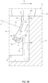
Figure 3B is a schematic sectional front view, with parts removed for clarity, of an enlarged portion of the detail ofFigure 3A ; -
Figure 4 is a schematic sectional front view, with parts removed for clarity, of the detail offigure 3 according a prior art solution not part of the present invention. - In
figure 1 reference numeral 1 indicates a gas turbine assembly (schematically shown inFigure 1 ). - The gas turbine assembly 1 comprises a
compressor 3, acombustion chamber 4, a gas turbine 5 and a generator (for simplicity, not shown in the attached figures). - The
compressor 3, turbine 5 and generator (not shown) are mounted on the same shaft to form a rotor 8, which is housed instator casings 9 and extends along an axis A. - In greater detail, the rotor 8 comprises a
front shaft 10, a plurality ofrotor assemblies 11 and arear shaft 13. - Each
rotor assembly 11 comprises arotor disk 15 and a plurality ofrotor blades 16 coupled to therotor disk 15 and radially arranged. - The plurality of
rotor disks 15 are arranged in succession between thefront shaft 10 and therear shaft 13 and preferably clamped as a pack by acentral tie rod 14. As an alternative, the rotor disks may be welded together. - A
central shaft 17 separates therotor disks 15 of thecompressor 3 from therotor disks 15 of the turbine 5 and extends through thecombustion chamber 4. - Further,
stator assemblies 22 are alternated with thecompressor rotor assemblies 11. - Each
stator assembly 22 comprises astator ring 24 and a plurality ofstator vanes 25, which are radially arranged and coupled to thestator ring 24 and to therespective stator casing 9. - In
figure 2 an enlarged view of astator assembly 22 between tworotor assemblies 11 in thecompressor 3 is shown. - Arrow D indicates the direction of the air flow flowing in a
compression channel 26 of thecompressor 3. - Between the
rotor assemblies 11 and thestator assembly 22 inter-assembly cavities 27 are arranged. - In particular, each
stator assembly 22 defines a leadinginter-assembly cavity 27a and a trailinginter-assembly cavity 27b, wherein the leadinginter-assembly cavity 27a is upstream the trailinginter-assembly cavity 27b along the hot gas flow direction D. - With reference to
figure 2 andfigure 3 , thestator ring 24 extends about therespective rotor disk 15 without touching it. - In particular, the
stator ring 24 comprises a leadingwall 30, atrailing wall 31 and anaxial wall 32 extending between the leadingwall 30 and thetrailing wall 31. The leadingwall 30 is upstream thetrailing wall 31 along the air flow direction D. - Preferably, leading
wall 30 and trailingwall 31 are radially arranged with respect to axis A. The leadingwall 30 is provided with an annular leadingface 33a and thetrailing wall 31 is provided with an annular trailingface 33b. - Between the
axial wall 32 of thestator ring 24 and therespective rotor disk 15 anaxial gap 34 is present. - In said axial gap 34 a
labyrinth seal 35 is arranged. - As schematically shown in
figure 3A , thelabyrinth seal 35 is defined by a plurality ofteeth 36 protruding from theaxial wall 32 and a plurality of opposite and staggeredteeth 37 protruding from therespective rotor disk 15. - The plurality of
stator vanes 25 are coupled alongside one another to thestator ring 24. - According to the invention, the
trailing wall 31 is shaped so as to define acavity 40 which has at least one opening 41 facing a rotating part of therotor assembly 11. The rotating part of the rotor assembly can be arotor disk 15 or a portion of a root of arotor blade 16. - The
cavity 40 is shaped so as to obtain a recirculation of the air entering the trailinginter-assembly cavity 27b. - In particular, the
cavity 40 is an open cavity extending along an annular path on the annular trailingradial face 33b of thetrailing wall 31. - With reference to the enlarged view of
figure 3B , the annulartrailing face 33b is provided with an outerplanar portion 42 at the outer edge facing the inlet of the trailinginter-assembly cavity 27b and an innerplanar portion 43 at the inner edge in contact with theaxial wall 32. The outerplanar portion 42 and the innerplanar portion 43 are radially arranged. - The radial length of the outer
planar portion 42 is preferably lower than the radial length of the innerplanar portion 43. - According to a variant not shown, the radial length of the outer
planar portion 42 can be substantially equal to the radial length of the innerplanar portion 43. - The
cavity 40 is arranged between the outerplanar portion 42 and the innerplanar portion 43. - In particular, the
cavity 40 is defined by aconcave portion 45 having at least one radius of curvature R1 and aconvex portion 46 having at least one radius of curvature R2. - The
concave portion 45 preferably extends so as to subtend an angle α comprised between 10°- 60°. - The
convex portion 46 preferably extends so as to subtend an angle β comprised between 90° - 270°. - The
convex portion 46 extends so to define arounded section 47 of thecavity 40 for allowing air recirculating. - At the meeting between the inner
planar portion 43 and the convex portion 46 a kick-out edge 48 is defined. - The kick-
out edge 48 has a radial height (intended as the measure from the axis A along a radial direction) greater than the radial height of the innest point P of theconvex portion 46. - While the
concave portion 45 defines aninlet edge 49. - According to a variant not shown, between the
concave portion 45 and the convex portion 46 a further planar portion can be arranged, preferably radially arranged. - In use, the air coming from the
compression channel 26 enters the trailinginter-assembly cavity 27b and is guided in thecavity 40 where circulates and is swirled towards thecompression channel 26 as shown by the arrows infigure 3A and3B . - In particular, the air coming from the
compression channel 26 enters the trailinginter-assembly cavity 27b and is firstly deflected inward by theconcave portion 45, then it is recirculated by theconvex portion 46 to generate a vortex inside therounded section 47 and finally it is ejected again in the trailinginter-assembly cavity 27b with a direction mostly opposite to the entering direction. - Eventually, it may happen that a small amount of air ejected from the
cavity 40 impacts the rotating part of therotor assembly 11 facing it and it is directed at lower radius towards theair gap 34. In this case, however, the strong pressure losses provided by the vortexes inside thecavity 40 and by thelabyrinth seal 35 prevents the airflow to reach the leadinginter-assembly cavity 27a and so to be ejected upstream thevane 25. - In this way, an aerodynamic sealing barrier against back-flow recirculation around the
compressor stator ring 24 is obtained. The sealing effect is stronger than the one obtained by traditional devices currently used as labyrinth seals (seefig. 4 ). - Moreover, the
cavity 40 is not involved in any variation of the clearance in theaxial gap 34. Therefore, it provides a constant and reliable sealing effectiveness during all operating conditions of the gas turbine assembly. - Finally, the shape and the dimensions of the
cavity 40 do not affect the mechanical reliability of thestator ring 24 and, if needed, it can be also used to improve the static and modal response of the ring stator by modifying its mass. - Finally, it is clear that modifications and variants can be made to the stator assembly and to the compressor described herein without departing from the scope of the present invention, as defined in the appended claims.
Claims (13)
- Stator assembly (22) for a compressor of a gas turbine assembly wherein air flows along a direction (D); the stator assembly comprising a stator ring (24), which extends about a longitudinal axis (A) and comprises a leading wall (30) and a trailing wall (31); the leading wall (30) being arranged upstream the trailing wall (31) along the air flow direction (D); the trailing wall (31) being is shaped so as to define an open cavity (40).
- Stator assembly according to claim 1, wherein trailing wall (31) defines an annular trailing face (33b); the open cavity (40) extending along an annular path on the annular trailing face (33b) of the trailing wall (31).
- Stator assembly according to any of the foregoing claims, wherein the cavity (40) comprises a rounded section (47) for promoting air recirculation.
- Stator assembly according to claim 3, wherein the cavity (40) is defined by a concave portion (45) having at least one radius of curvature (R1) and at least one convex portion (46) having a radius of curvature (R2); the convex portion (46) comprises the rounded section (47).
- Stator assembly according to claim 4, wherein the concave portion (45) extends so as to subtend an angle (α) comprised between 10°- 60°.
- Stator assembly according to claim 4 or 5, wherein the convex portion (46) extends so as to subtend an angle (β) comprised between 90° - 270°.
- Stator assembly according to any of claims 4-6, wherein the cavity (40) is provided with a kick-out edge (48); the kick-out edge (48) has a radial height greater than the radial height of the innest point (P) of the convex portion (46).
- Stator assembly according to any of claims 3-7, wherein the annular trailing face (33b) is provided with an outer planar portion (42) and an inner planar portion (43); the cavity (40) being arranged between the outer planar portion (42) and the inner planar portion (43).
- Stator assembly according to claim 8, wherein the outer planar portion (42) and the inner planar portion (43) are radially arranged.
- Stator assembly according to claim 8 or 9, wherein the radial length of the outer planar portion (42) is lower or equal than the radial length of the inner planar portion (43) .
- Compressor extending along a longitudinal axis (A) and comprising:- a compression channel (26) along which air flows in a direction (D);- a plurality of rotor assemblies (11), each of which comprises a rotor disk (15) and a plurality of rotor blades (16) radially arranged and coupled to the rotor disk (15);- a plurality of stator assemblies (22); the stator assemblies (22) and the rotor assemblies (11) being alternated along the axial direction (A) and spaced out from each other so as to define, for each stator assembly (22), a leading inter-assembly cavity (27a) and a trailing inter-assembly cavity (27b); wherein the leading inter-assembly cavity (27a) is upstream the trailing inter-assembly cavity (27b) along the hot gas flow direction (D);- at least one of the stator assemblies (22) being of the type claimed in anyone of the foregoing claims.
- Compressor according to claim 11, wherein the stator ring (34) comprises an axial wall (32) extending between the leading wall (30) and the trailing wall (31); the stator ring (34) being arranged about a respective rotor disk (15) so as to leave an axial gap (34), between the axial wall (32) of the stator ring (24) and the respective rotor disk (15) .
- Compressor according to claim 12, comprising at least one labyrinth seal (35) in the axial gap (34).
Priority Applications (2)
| Application Number | Priority Date | Filing Date | Title |
|---|---|---|---|
| EP21425077.1A EP4206441B1 (en) | 2021-12-30 | 2021-12-30 | Stator assembly for a compressor of a gas turbine assembly and compressor for a gas turbine assembly |
| CN202211611875.6A CN116378779A (en) | 2021-12-30 | 2022-12-15 | Stator assembly and gas turbine assembly including the same |
Applications Claiming Priority (1)
| Application Number | Priority Date | Filing Date | Title |
|---|---|---|---|
| EP21425077.1A EP4206441B1 (en) | 2021-12-30 | 2021-12-30 | Stator assembly for a compressor of a gas turbine assembly and compressor for a gas turbine assembly |
Publications (2)
| Publication Number | Publication Date |
|---|---|
| EP4206441A1 true EP4206441A1 (en) | 2023-07-05 |
| EP4206441B1 EP4206441B1 (en) | 2024-11-27 |
Family
ID=80119299
Family Applications (1)
| Application Number | Title | Priority Date | Filing Date |
|---|---|---|---|
| EP21425077.1A Active EP4206441B1 (en) | 2021-12-30 | 2021-12-30 | Stator assembly for a compressor of a gas turbine assembly and compressor for a gas turbine assembly |
Country Status (2)
| Country | Link |
|---|---|
| EP (1) | EP4206441B1 (en) |
| CN (1) | CN116378779A (en) |
Citations (4)
| Publication number | Priority date | Publication date | Assignee | Title |
|---|---|---|---|---|
| US8075256B2 (en) * | 2008-09-25 | 2011-12-13 | Siemens Energy, Inc. | Ingestion resistant seal assembly |
| US8388310B1 (en) * | 2008-01-30 | 2013-03-05 | Siemens Energy, Inc. | Turbine disc sealing assembly |
| US20190360350A1 (en) * | 2017-02-17 | 2019-11-28 | Mitsubishi Heavy Industries, Ltd. | Axial flow rotating machine, and rotor blade member |
| US10851662B2 (en) * | 2017-08-17 | 2020-12-01 | DOOSAN Heavy Industries Construction Co., LTD | Sealing structure for turbines, and turbine and gas turbine having the same |
-
2021
- 2021-12-30 EP EP21425077.1A patent/EP4206441B1/en active Active
-
2022
- 2022-12-15 CN CN202211611875.6A patent/CN116378779A/en active Pending
Patent Citations (4)
| Publication number | Priority date | Publication date | Assignee | Title |
|---|---|---|---|---|
| US8388310B1 (en) * | 2008-01-30 | 2013-03-05 | Siemens Energy, Inc. | Turbine disc sealing assembly |
| US8075256B2 (en) * | 2008-09-25 | 2011-12-13 | Siemens Energy, Inc. | Ingestion resistant seal assembly |
| US20190360350A1 (en) * | 2017-02-17 | 2019-11-28 | Mitsubishi Heavy Industries, Ltd. | Axial flow rotating machine, and rotor blade member |
| US10851662B2 (en) * | 2017-08-17 | 2020-12-01 | DOOSAN Heavy Industries Construction Co., LTD | Sealing structure for turbines, and turbine and gas turbine having the same |
Also Published As
| Publication number | Publication date |
|---|---|
| EP4206441B1 (en) | 2024-11-27 |
| CN116378779A (en) | 2023-07-04 |
Similar Documents
| Publication | Publication Date | Title |
|---|---|---|
| CA2688099C (en) | Centrifugal compressor forward thrust and turbine cooling apparatus | |
| CN102187061B (en) | Gas turbine | |
| JP5879084B2 (en) | Turbomachine seal assembly | |
| EP2206902A2 (en) | Turbine cooling air from a centrifugal compressor | |
| KR20140052864A (en) | Axial flow turbine | |
| JP2016125486A (en) | Gas turbine sealing | |
| US20090123275A1 (en) | Apparatus for eliminating compressor stator vibration induced by TIP leakage vortex bursting | |
| KR20200045817A (en) | Ring segment and gas turbine having the same | |
| CN110431286A (en) | Tip Balance Slots for Turbines | |
| US3756740A (en) | Turbine stage | |
| CN111878451A (en) | Axial compressor sealing device, axial compressor and gas turbine | |
| EP4206441B1 (en) | Stator assembly for a compressor of a gas turbine assembly and compressor for a gas turbine assembly | |
| EP3663522B1 (en) | Stator assembly for a gas turbine and gas turbine comprising said stator assembly | |
| EP3287605B1 (en) | Rim seal for gas turbine engine | |
| KR102659819B1 (en) | Sealing assembly and turbo-machine comprising the same | |
| JP5439164B2 (en) | Gas turbine cooling channel structure, gas turbine, and adjustment method of gas turbine cooling channel structure | |
| EP4230844B1 (en) | Stator assembly for a gas turbine and gas turbine comprising said stator assembly | |
| EP3816402B1 (en) | Stator assembly for a gas turbine and gas turbine comprising said stator assembly | |
| KR20220035649A (en) | Stator and turbo-machine comprising the same | |
| US20250003347A1 (en) | High-pressure gas turbine for turbomachine and turbomachine | |
| US12624639B2 (en) | Turbine module for a turbomachine | |
| US11536158B2 (en) | Turbomachine | |
| US12486773B2 (en) | Radial turbine impeller | |
| CN209800031U (en) | Labyrinth seal system and aeroengine | |
| US20260110251A1 (en) | Air injection casing for a turbomachine |
Legal Events
| Date | Code | Title | Description |
|---|---|---|---|
| PUAI | Public reference made under article 153(3) epc to a published international application that has entered the european phase |
Free format text: ORIGINAL CODE: 0009012 |
|
| STAA | Information on the status of an ep patent application or granted ep patent |
Free format text: STATUS: THE APPLICATION HAS BEEN PUBLISHED |
|
| AK | Designated contracting states |
Kind code of ref document: A1 Designated state(s): AL AT BE BG CH CY CZ DE DK EE ES FI FR GB GR HR HU IE IS IT LI LT LU LV MC MK MT NL NO PL PT RO RS SE SI SK SM TR |
|
| STAA | Information on the status of an ep patent application or granted ep patent |
Free format text: STATUS: REQUEST FOR EXAMINATION WAS MADE |
|
| 17P | Request for examination filed |
Effective date: 20231211 |
|
| RBV | Designated contracting states (corrected) |
Designated state(s): AL AT BE BG CH CY CZ DE DK EE ES FI FR GB GR HR HU IE IS IT LI LT LU LV MC MK MT NL NO PL PT RO RS SE SI SK SM TR |
|
| GRAP | Despatch of communication of intention to grant a patent |
Free format text: ORIGINAL CODE: EPIDOSNIGR1 |
|
| STAA | Information on the status of an ep patent application or granted ep patent |
Free format text: STATUS: GRANT OF PATENT IS INTENDED |
|
| RIC1 | Information provided on ipc code assigned before grant |
Ipc: F01D 11/00 20060101AFI20240111BHEP |
|
| INTG | Intention to grant announced |
Effective date: 20240214 |
|
| P01 | Opt-out of the competence of the unified patent court (upc) registered |
Effective date: 20240430 |
|
| GRAJ | Information related to disapproval of communication of intention to grant by the applicant or resumption of examination proceedings by the epo deleted |
Free format text: ORIGINAL CODE: EPIDOSDIGR1 |
|
| STAA | Information on the status of an ep patent application or granted ep patent |
Free format text: STATUS: REQUEST FOR EXAMINATION WAS MADE |
|
| INTC | Intention to grant announced (deleted) | ||
| GRAP | Despatch of communication of intention to grant a patent |
Free format text: ORIGINAL CODE: EPIDOSNIGR1 |
|
| STAA | Information on the status of an ep patent application or granted ep patent |
Free format text: STATUS: GRANT OF PATENT IS INTENDED |
|
| INTG | Intention to grant announced |
Effective date: 20240726 |
|
| GRAS | Grant fee paid |
Free format text: ORIGINAL CODE: EPIDOSNIGR3 |
|
| GRAA | (expected) grant |
Free format text: ORIGINAL CODE: 0009210 |
|
| STAA | Information on the status of an ep patent application or granted ep patent |
Free format text: STATUS: THE PATENT HAS BEEN GRANTED |
|
| AK | Designated contracting states |
Kind code of ref document: B1 Designated state(s): AL AT BE BG CH CY CZ DE DK EE ES FI FR GB GR HR HU IE IS IT LI LT LU LV MC MK MT NL NO PL PT RO RS SE SI SK SM TR |
|
| REG | Reference to a national code |
Ref country code: GB Ref legal event code: FG4D |
|
| REG | Reference to a national code |
Ref country code: CH Ref legal event code: EP |
|
| REG | Reference to a national code |
Ref country code: IE Ref legal event code: FG4D |
|
| REG | Reference to a national code |
Ref country code: DE Ref legal event code: R096 Ref document number: 602021022372 Country of ref document: DE |
|
| REG | Reference to a national code |
Ref country code: LT Ref legal event code: MG9D |
|
| REG | Reference to a national code |
Ref country code: NL Ref legal event code: MP Effective date: 20241127 |
|
| PG25 | Lapsed in a contracting state [announced via postgrant information from national office to epo] |
Ref country code: IS Free format text: LAPSE BECAUSE OF FAILURE TO SUBMIT A TRANSLATION OF THE DESCRIPTION OR TO PAY THE FEE WITHIN THE PRESCRIBED TIME-LIMIT Effective date: 20250327 Ref country code: PT Free format text: LAPSE BECAUSE OF FAILURE TO SUBMIT A TRANSLATION OF THE DESCRIPTION OR TO PAY THE FEE WITHIN THE PRESCRIBED TIME-LIMIT Effective date: 20250327 Ref country code: HR Free format text: LAPSE BECAUSE OF FAILURE TO SUBMIT A TRANSLATION OF THE DESCRIPTION OR TO PAY THE FEE WITHIN THE PRESCRIBED TIME-LIMIT Effective date: 20241127 |
|
| PG25 | Lapsed in a contracting state [announced via postgrant information from national office to epo] |
Ref country code: FI Free format text: LAPSE BECAUSE OF FAILURE TO SUBMIT A TRANSLATION OF THE DESCRIPTION OR TO PAY THE FEE WITHIN THE PRESCRIBED TIME-LIMIT Effective date: 20241127 Ref country code: NL Free format text: LAPSE BECAUSE OF FAILURE TO SUBMIT A TRANSLATION OF THE DESCRIPTION OR TO PAY THE FEE WITHIN THE PRESCRIBED TIME-LIMIT Effective date: 20241127 |
|
| REG | Reference to a national code |
Ref country code: AT Ref legal event code: MK05 Ref document number: 1745887 Country of ref document: AT Kind code of ref document: T Effective date: 20241127 |
|
| PG25 | Lapsed in a contracting state [announced via postgrant information from national office to epo] |
Ref country code: BG Free format text: LAPSE BECAUSE OF FAILURE TO SUBMIT A TRANSLATION OF THE DESCRIPTION OR TO PAY THE FEE WITHIN THE PRESCRIBED TIME-LIMIT Effective date: 20241127 |
|
| PG25 | Lapsed in a contracting state [announced via postgrant information from national office to epo] |
Ref country code: ES Free format text: LAPSE BECAUSE OF FAILURE TO SUBMIT A TRANSLATION OF THE DESCRIPTION OR TO PAY THE FEE WITHIN THE PRESCRIBED TIME-LIMIT Effective date: 20241127 |
|
| PG25 | Lapsed in a contracting state [announced via postgrant information from national office to epo] |
Ref country code: NO Free format text: LAPSE BECAUSE OF FAILURE TO SUBMIT A TRANSLATION OF THE DESCRIPTION OR TO PAY THE FEE WITHIN THE PRESCRIBED TIME-LIMIT Effective date: 20250227 |
|
| PG25 | Lapsed in a contracting state [announced via postgrant information from national office to epo] |
Ref country code: AT Free format text: LAPSE BECAUSE OF FAILURE TO SUBMIT A TRANSLATION OF THE DESCRIPTION OR TO PAY THE FEE WITHIN THE PRESCRIBED TIME-LIMIT Effective date: 20241127 Ref country code: GR Free format text: LAPSE BECAUSE OF FAILURE TO SUBMIT A TRANSLATION OF THE DESCRIPTION OR TO PAY THE FEE WITHIN THE PRESCRIBED TIME-LIMIT Effective date: 20250228 Ref country code: LV Free format text: LAPSE BECAUSE OF FAILURE TO SUBMIT A TRANSLATION OF THE DESCRIPTION OR TO PAY THE FEE WITHIN THE PRESCRIBED TIME-LIMIT Effective date: 20241127 |
|
| PG25 | Lapsed in a contracting state [announced via postgrant information from national office to epo] |
Ref country code: PL Free format text: LAPSE BECAUSE OF FAILURE TO SUBMIT A TRANSLATION OF THE DESCRIPTION OR TO PAY THE FEE WITHIN THE PRESCRIBED TIME-LIMIT Effective date: 20241127 |
|
| PG25 | Lapsed in a contracting state [announced via postgrant information from national office to epo] |
Ref country code: RS Free format text: LAPSE BECAUSE OF FAILURE TO SUBMIT A TRANSLATION OF THE DESCRIPTION OR TO PAY THE FEE WITHIN THE PRESCRIBED TIME-LIMIT Effective date: 20250227 |
|
| PG25 | Lapsed in a contracting state [announced via postgrant information from national office to epo] |
Ref country code: SM Free format text: LAPSE BECAUSE OF FAILURE TO SUBMIT A TRANSLATION OF THE DESCRIPTION OR TO PAY THE FEE WITHIN THE PRESCRIBED TIME-LIMIT Effective date: 20241127 |
|
| PG25 | Lapsed in a contracting state [announced via postgrant information from national office to epo] |
Ref country code: DK Free format text: LAPSE BECAUSE OF FAILURE TO SUBMIT A TRANSLATION OF THE DESCRIPTION OR TO PAY THE FEE WITHIN THE PRESCRIBED TIME-LIMIT Effective date: 20241127 |
|
| PG25 | Lapsed in a contracting state [announced via postgrant information from national office to epo] |
Ref country code: EE Free format text: LAPSE BECAUSE OF FAILURE TO SUBMIT A TRANSLATION OF THE DESCRIPTION OR TO PAY THE FEE WITHIN THE PRESCRIBED TIME-LIMIT Effective date: 20241127 |
|
| PG25 | Lapsed in a contracting state [announced via postgrant information from national office to epo] |
Ref country code: RO Free format text: LAPSE BECAUSE OF FAILURE TO SUBMIT A TRANSLATION OF THE DESCRIPTION OR TO PAY THE FEE WITHIN THE PRESCRIBED TIME-LIMIT Effective date: 20241127 |
|
| PG25 | Lapsed in a contracting state [announced via postgrant information from national office to epo] |
Ref country code: SK Free format text: LAPSE BECAUSE OF FAILURE TO SUBMIT A TRANSLATION OF THE DESCRIPTION OR TO PAY THE FEE WITHIN THE PRESCRIBED TIME-LIMIT Effective date: 20241127 |
|
| PG25 | Lapsed in a contracting state [announced via postgrant information from national office to epo] |
Ref country code: CZ Free format text: LAPSE BECAUSE OF FAILURE TO SUBMIT A TRANSLATION OF THE DESCRIPTION OR TO PAY THE FEE WITHIN THE PRESCRIBED TIME-LIMIT Effective date: 20241127 |
|
| REG | Reference to a national code |
Ref country code: CH Ref legal event code: PL |
|
| PG25 | Lapsed in a contracting state [announced via postgrant information from national office to epo] |
Ref country code: LU Free format text: LAPSE BECAUSE OF NON-PAYMENT OF DUE FEES Effective date: 20241230 |
|
| REG | Reference to a national code |
Ref country code: DE Ref legal event code: R097 Ref document number: 602021022372 Country of ref document: DE |
|
| PG25 | Lapsed in a contracting state [announced via postgrant information from national office to epo] |
Ref country code: SE Free format text: LAPSE BECAUSE OF FAILURE TO SUBMIT A TRANSLATION OF THE DESCRIPTION OR TO PAY THE FEE WITHIN THE PRESCRIBED TIME-LIMIT Effective date: 20241127 |
|
| PG25 | Lapsed in a contracting state [announced via postgrant information from national office to epo] |
Ref country code: MC Free format text: LAPSE BECAUSE OF FAILURE TO SUBMIT A TRANSLATION OF THE DESCRIPTION OR TO PAY THE FEE WITHIN THE PRESCRIBED TIME-LIMIT Effective date: 20241127 |
|
| PLBE | No opposition filed within time limit |
Free format text: ORIGINAL CODE: 0009261 |
|
| STAA | Information on the status of an ep patent application or granted ep patent |
Free format text: STATUS: NO OPPOSITION FILED WITHIN TIME LIMIT |
|
| REG | Reference to a national code |
Ref country code: BE Ref legal event code: MM Effective date: 20241231 |
|
| PG25 | Lapsed in a contracting state [announced via postgrant information from national office to epo] |
Ref country code: BE Free format text: LAPSE BECAUSE OF NON-PAYMENT OF DUE FEES Effective date: 20241231 |
|
| PG25 | Lapsed in a contracting state [announced via postgrant information from national office to epo] |
Ref country code: FR Free format text: LAPSE BECAUSE OF NON-PAYMENT OF DUE FEES Effective date: 20250127 |
|
| PG25 | Lapsed in a contracting state [announced via postgrant information from national office to epo] |
Ref country code: CH Free format text: LAPSE BECAUSE OF NON-PAYMENT OF DUE FEES Effective date: 20241231 |
|
| PG25 | Lapsed in a contracting state [announced via postgrant information from national office to epo] |
Ref country code: IE Free format text: LAPSE BECAUSE OF NON-PAYMENT OF DUE FEES Effective date: 20241230 |
|
| 26N | No opposition filed |
Effective date: 20250828 |
|
| PGFP | Annual fee paid to national office [announced via postgrant information from national office to epo] |
Ref country code: DE Payment date: 20251222 Year of fee payment: 5 |
|
| PGFP | Annual fee paid to national office [announced via postgrant information from national office to epo] |
Ref country code: IT Payment date: 20251231 Year of fee payment: 5 |
|
| PG25 | Lapsed in a contracting state [announced via postgrant information from national office to epo] |
Ref country code: CY Free format text: LAPSE BECAUSE OF FAILURE TO SUBMIT A TRANSLATION OF THE DESCRIPTION OR TO PAY THE FEE WITHIN THE PRESCRIBED TIME-LIMIT Effective date: 20241127 |
|
| PG25 | Lapsed in a contracting state [announced via postgrant information from national office to epo] |
Ref country code: TR Free format text: LAPSE BECAUSE OF FAILURE TO SUBMIT A TRANSLATION OF THE DESCRIPTION OR TO PAY THE FEE WITHIN THE PRESCRIBED TIME-LIMIT Effective date: 20241127 |
|
| PG25 | Lapsed in a contracting state [announced via postgrant information from national office to epo] |
Ref country code: HU Free format text: LAPSE BECAUSE OF FAILURE TO SUBMIT A TRANSLATION OF THE DESCRIPTION OR TO PAY THE FEE WITHIN THE PRESCRIBED TIME-LIMIT; INVALID AB INITIO Effective date: 20211230 |
|
| PG25 | Lapsed in a contracting state [announced via postgrant information from national office to epo] |
Ref country code: SI Free format text: LAPSE BECAUSE OF FAILURE TO SUBMIT A TRANSLATION OF THE DESCRIPTION OR TO PAY THE FEE WITHIN THE PRESCRIBED TIME-LIMIT Effective date: 20241127 |
|
| PG25 | Lapsed in a contracting state [announced via postgrant information from national office to epo] |
Ref country code: LT Free format text: LAPSE BECAUSE OF FAILURE TO SUBMIT A TRANSLATION OF THE DESCRIPTION OR TO PAY THE FEE WITHIN THE PRESCRIBED TIME-LIMIT Effective date: 20241127 |