EP4206404A1 - Holding device and disassembly method for aquatic structure - Google Patents
Holding device and disassembly method for aquatic structure Download PDFInfo
- Publication number
- EP4206404A1 EP4206404A1 EP22211596.6A EP22211596A EP4206404A1 EP 4206404 A1 EP4206404 A1 EP 4206404A1 EP 22211596 A EP22211596 A EP 22211596A EP 4206404 A1 EP4206404 A1 EP 4206404A1
- Authority
- EP
- European Patent Office
- Prior art keywords
- holding
- aquatic structure
- aquatic
- water
- holding device
- Prior art date
- Legal status (The legal status is an assumption and is not a legal conclusion. Google has not performed a legal analysis and makes no representation as to the accuracy of the status listed.)
- Granted
Links
Images






Classifications
-
- E—FIXED CONSTRUCTIONS
- E02—HYDRAULIC ENGINEERING; FOUNDATIONS; SOIL SHIFTING
- E02B—HYDRAULIC ENGINEERING
- E02B17/00—Artificial islands mounted on piles or like supports, e.g. platforms on raisable legs or offshore constructions; Construction methods therefor
-
- B—PERFORMING OPERATIONS; TRANSPORTING
- B63—SHIPS OR OTHER WATERBORNE VESSELS; RELATED EQUIPMENT
- B63B—SHIPS OR OTHER WATERBORNE VESSELS; EQUIPMENT FOR SHIPPING
- B63B35/00—Vessels or similar floating structures specially adapted for specific purposes and not otherwise provided for
- B63B35/003—Vessels or similar floating structures specially adapted for specific purposes and not otherwise provided for for transporting very large loads, e.g. offshore structure modules
-
- B—PERFORMING OPERATIONS; TRANSPORTING
- B63—SHIPS OR OTHER WATERBORNE VESSELS; RELATED EQUIPMENT
- B63B—SHIPS OR OTHER WATERBORNE VESSELS; EQUIPMENT FOR SHIPPING
- B63B77/00—Transporting or installing offshore structures on site using buoyancy forces, e.g. using semi-submersible barges, ballasting the structure or transporting of oil-and-gas platforms
-
- E—FIXED CONSTRUCTIONS
- E02—HYDRAULIC ENGINEERING; FOUNDATIONS; SOIL SHIFTING
- E02B—HYDRAULIC ENGINEERING
- E02B17/00—Artificial islands mounted on piles or like supports, e.g. platforms on raisable legs or offshore constructions; Construction methods therefor
- E02B2017/0052—Removal or dismantling of offshore structures from their offshore location
-
- Y—GENERAL TAGGING OF NEW TECHNOLOGICAL DEVELOPMENTS; GENERAL TAGGING OF CROSS-SECTIONAL TECHNOLOGIES SPANNING OVER SEVERAL SECTIONS OF THE IPC; TECHNICAL SUBJECTS COVERED BY FORMER USPC CROSS-REFERENCE ART COLLECTIONS [XRACs] AND DIGESTS
- Y02—TECHNOLOGIES OR APPLICATIONS FOR MITIGATION OR ADAPTATION AGAINST CLIMATE CHANGE
- Y02E—REDUCTION OF GREENHOUSE GAS [GHG] EMISSIONS, RELATED TO ENERGY GENERATION, TRANSMISSION OR DISTRIBUTION
- Y02E10/00—Energy generation through renewable energy sources
- Y02E10/70—Wind energy
- Y02E10/727—Offshore wind turbines
Definitions
- the present disclosure relates to a holding device and a disassembly method for an aquatic structure.
- an inexpensive disassembly method avoiding high-place work as much as possible may include a method in which the root of the structure is cut to topple the structure before disassembling the structure (as in Patent Document 1, for example).
- the structure is cut by using, for example, explosives or other mechanical cutting methods.
- Patent Document 1 JP 4828314 B
- the present disclosure has been made in view of such circumstances, and an object of the present disclosure is to provide a holding device and a disassembly method by which an aquatic structure can be detached from the bottom of water before disassembly without posing a danger to surroundings and without causing contaminants attached to the aquatic structure and contaminants contained in the aquatic structure to scatter or flow out into water.
- the holding device and the disassembly method of the present disclosure adopt the following means.
- a holding device for holding a bottom-mounted type aquatic structure extending from a bottom of water to above the water, and includes a floating body floating on the water, a holding portion configured to hold the aquatic structure, and a supporting portion disposed at the floating body and configured to rotatably support the holding portion about an axis. The holding portion is rotated so as to tilt over the aquatic structure.
- a disassembly method is a disassembly method for disassembling a bottom-mounted type aquatic structure using a holding device including a floating body floating on water, a holding portion configured to hold the aquatic structure, and a supporting portion disposed at the floating body and configured to rotatably support the holding portion about an axis, and includes steps of holding the aquatic structure with the holding portion, detaching the aquatic structure held by the holding portion from a bottom of water, and tilting the aquatic structure by rotating the holding portion holding the aquatic structure detached from the bottom of water about the axis on the floating body.
- an aquatic structure can be detached from the bottom of water and disassembled without posing a danger to surroundings and without causing contaminants attached to the aquatic structure and contaminants contained in the aquatic structure to scatter or flow out into water.
- a holding device and a disassembly method are a device and a method used in disassembling an aquatic structure 200.
- disassembling here means not an operation of disassembling the aquatic structure 200 itself, but an operation of detaching the aquatic structure 200 from a water bottom 303 and making the aquatic structure 200 ready for transfer from an installation location.
- the aquatic structure 200 is a bottom-mounted structure extending from the water bottom 303 to above the water when mounted on the water bottom 303.
- the aquatic structure 200 is a bottom-mounted structure extending in the vertical direction (that is, having a longitudinal direction along the vertical direction) when mounted on the water bottom 303.
- Examples of the aquatic structure 200 include a meteorological tower, a leg structure for an offshore facility, a lighthouse, a power transmission tower, and a windmill for power generation.
- the aquatic structure 200 includes a foundation 210 and a structure body 220.
- the foundation 210 extends in the vertical direction and a lower portion of the foundation 210 is driven into the water bottom 303.
- the foundation 210 may be a jacket-type foundation, a tripot-type foundation, or a tripile-type foundation, in addition to the illustrated monopile-type foundation.
- the specific form of the structure of the foundation 210 is not limited as long as the foundation 210 is a bottom-mounted type foundation.
- the structure body 220 is provided at an upper portion of the foundation 210 in the vertical direction, and a portion including an upper end of the structure body 220 is exposed above a water surface 301.
- the structure body 220 is a part that performs the substantial function of the aquatic structure 200. Since the structure body 220 includes equipment necessary for performing this function, the weight of the structure body 220 is often heavier than the weight of the foundation 210.
- a holding device and a disassembly method according to a first embodiment of the present disclosure will be described below with reference to FIGS. 2 to 5 .
- a holding device 101 includes a floating body structure (floating body) 110, a holding mechanism (holding portion) 120, and a supporting mechanism (supporting portion) 130.
- the floating body structure 110 is a part that floats in water (on water) by a buoyant force.
- the floating body structure 110 is designed to generate a sufficient buoyant force so as not to sink even when the entire weight of the disassembled aquatic structure 200 is applied.
- the floating body structure 110 includes a recess 111 extending in a predetermined direction. Due to the recess 111, the floating body structure 110 has a U-shape in a plan view.
- the recess 111 is a space or a gap into which the aquatic structure 200 and the holding mechanism 120 enter when the aquatic structure 200 is disassembled.
- the floating body structure 110 is not limited to the above-described configuration (U-shape).
- the configuration of the floating body structure 110 may be changed by providing a mechanism configured to open and close an opening of the recess 111 such that the opening of the recess 111 is closed when the floating body structure 110 is in transit and the opening opens when the aquatic structure 200 is tilted.
- Two supporting mechanisms 130 are disposed at an upper surface of the floating body structure 110.
- the two supporting mechanisms 130 are disposed opposing each other across the recess 111.
- the supporting mechanism 130 is a part that rotatably supports a support shaft 121a included in the holding mechanism 120.
- the holding mechanism 120 is a part that holds and grips the aquatic structure 200.
- the holding mechanism 120 is disposed between the supporting mechanisms 130 that oppose each other.
- the holding mechanism 120 includes a rotating portion 121 and a holding arm 122.
- the rotating portion 121 is a long structure extending in a predetermined direction.
- the rotating portion 121 includes the support shaft 121a having an axis of rotation (axis) X along the horizontal direction.
- the support shaft 121a protrudes on both sides of the rotating portion 121.
- the support shaft 121a of the rotating portion 121 is supported by the supporting mechanisms 130. Accordingly, the rotating portion 121 and thus the holding mechanism 120 are rotatably supported by the supporting mechanisms 130.
- the holding arm 122 is a mechanism that holds and grips the aquatic structure 200.
- the holding arm 122 is provided at a plurality of locations along an extending direction of the rotating portion 121. Accordingly, the long aquatic structure 200 can be stably held at a plurality of locations. In the case of FIG. 2 , a total of three holding arms 122 are provided: two hold the structure body 220, and one holds the foundation 210.
- the holding arm 122 and the rotating portion 121 may be configured such that the holding arm 122 moves in the extending direction of the rotating portion 121 according to the dimension (height) of the aquatic structure 200.
- an extending direction of the holding mechanism 120 coincides with an extending direction of the aquatic structure 200.
- the holding mechanism 120 holds/is holding the aquatic structure 200, which is driven into the water bottom 303 and extends in the vertical direction, the extending direction of the holding mechanism 120 coincides with the vertical direction, similar to the aquatic structure 200.
- the holding mechanism 120 is disposed between the supporting mechanisms 130, and a lower portion of the holding mechanism 120 is located in the recess 111.
- the holding mechanism 120 when the holding mechanism 120 is not holding the aquatic structure 200, the extending direction of the holding mechanism 120 need not coincide with the extending direction of the aquatic structure 200, and the holding mechanism 120 may be positioned such that the extending direction of the holding mechanism 120 coincides with the horizontal direction, for example.
- the time when the holding mechanism 120 is not holding the aquatic structure 200 refers to, for example, a time when the holding device 101 is transferred to the vicinity of the aquatic structure 200 before the start of a disassembling operation.
- the holding mechanism 120 rotatably supported by the supporting mechanisms 130 is rotated about the axis of rotation X of the support shaft 121a by a drive unit (not illustrated).
- the drive unit includes, for example, an electric motor and a reducer including a plurality of gears.
- the holding device 101 is moved such that the aquatic structure 200 enters the recess 111 of the floating body structure 110.
- the holding device 101 is moved by, for example, towing by a ship.
- the holding device 101 may be provided with power so as to be self-propelled.
- the angle of the holding mechanism 120 is controlled such that the extending direction of the holding mechanism 120 coincides with the extending direction of the aquatic structure 200.
- This angle is controlled by using the drive unit described above.
- the aquatic structure 200 is held by the holding arms 122 of the holding mechanism 120 (holding step). Accordingly, the aquatic structure 200 is secured to the holding mechanism 120.
- contamination control measures such as covering a portion of the foundation 210, which has a cut surface 211, with a cover may be taken.
- the position of the cut surface 211 is as close to the water bottom 303 as possible.
- the weight of the structure body 220 is heavier than the weight of the foundation 210, and the position of the center of gravity G of the aquatic structure 200 tends to be located above the axis of rotation X in the vertical direction.
- the position of the cut surface 211 has been contrived such that the center of gravity G of the aquatic structure 200 after being detached from the water bottom 303 is located as close to the axis of rotation X as possible to reduce the torque required for rotating the holding mechanism 120.
- the cutting operation of the foundation 210 may be started before the holding step, and the aquatic structure 200 may be held by the holding mechanism 120 in the middle of the cutting operation.
- the aquatic structure 200 only needs to be held by the holding mechanism 120 before the aquatic structure 200 is completely detached from the water bottom 303.
- the cutting operation of the aquatic structure 200 is completed, and the aquatic structure 200 held by the holding mechanism 120 is completely detached from the water bottom 303 (cutting step). Accordingly, the system of the holding device 101 holding the aquatic structure 200 is completely separated from the water bottom 303.
- the holding mechanism 120 is rotated by using the drive unit (not illustrated) so as to tilt the aquatic structure 200 in a direction along which a cut end of the aquatic structure 200 passes through the recess 111 (a direction in which the cut end is lifted up) (tilting step).
- the holding mechanism 120 is rotated by the drive unit at a low speed in order to safely tilt the aquatic structure 200.
- the aquatic structure 200 is tilted until the aquatic structure 200 is placed on the floating body structure 110 with the extending direction of the aquatic structure 200 coincident with the horizontal direction.
- the aquatic structure 200 can be moved to the vicinity of land together with the holding device 101.
- the aquatic structure 200 placed on the holding device 101 is pulled up to land by, for example, a crane installed on land, so that the aquatic structure 200 can be safely disassembled on land.
- the holding device 101 includes the floating body structure 110 floating on the water, the holding mechanism 120 configured to hold the aquatic structure 200, and the supporting mechanisms 130 disposed at the floating body structure 110 and configured to rotatably support the holding mechanism 120 about an axis.
- the holding mechanism 120 is rotated such that the aquatic structure 200 is tilted, and thus, for example, the aquatic structure 200 extending in the vertical direction can be detached from the water bottom 303 and laid down on the floating body structure 110 while being held by the holding mechanism 120.
- the aquatic structure 200 can be detached from the water bottom 303 in a stable state, and the detached aquatic structure 200 can be stably tilted and laid down on the floating body structure 200.
- the aquatic structure 200 can be moved to land in a stable state, and then disassembled on land.
- the aquatic structure 200 can be detached from the water bottom 303 and disassembled without posing a danger to neighboring ships or the like and without causing contaminants attached to the aquatic structure 200 and contaminants contained in the aquatic structure 200 to scatter or flow out into water.
- the holding device 101 includes a drive unit configured to rotate the holding mechanism 120 rotatably supported by the supporting mechanisms 130, the holding mechanism 120 holding the aquatic structure 200 detached from the water bottom 303 can be freely rotated about the axis.
- the holding device and the disassembly method according to the present embodiment differ from those of the first embodiment in the structure of the floating body structure 110 and the structure of the supporting mechanism 130, but are identical to those of the first embodiment in other respects. Therefore, the same components are denoted by the same reference signs, and description thereof will be omitted.
- the holding device denoted by the reference sign 101 in the first embodiment is denoted by the reference sign 102 in the present embodiment.
- the supporting mechanism 130 is configured to temporarily release the rotatable support of the support shaft 121a.
- wheels 132 are provided at a lower portion of the supporting mechanism 130. Also, two rails 112 are laid parallel on the floating body structure 110.
- the supporting mechanisms 130 are placed movably along the rails 112 on the floating body structure 110 via the wheels 132.
- a supporting cutout 131 is formed in the supporting mechanism 130.
- the supporting cutout 131 is a U-shaped cutout extending in the horizontal direction.
- a semi-circular arc-shaped end of the supporting cutout 131 corresponds to the shape of the support axis 121a.
- the support shaft 121a When the support shaft 121a is held by the supporting cutout 131, the support shaft 121a is rotatably supported by the supporting mechanism 130.
- the system of the holding mechanism 120 holding the aquatic structure 200 is separated from the system of the floating body structure 110 including the supporting mechanisms 130.
- rocking motions of the floating body structure 110 can be prevented from being transmitted to the holding mechanism 120, and vibrations of the holding mechanism 120 can be prevented from being transmitted to the floating body structure 110.
- each inside surface of the recess 111 may be provided with a cushioning member 113 protruding toward the holding mechanism 120 (rotating portion 121).
- the material of the cushioning member 113 examples include a rubber material such as chloroprene, and a rubber material that is commercially-available as a fender.
- mechanical shock absorbing means such as a hydraulic damper or a metal spring can be used, or can be used in combination with the cushioning member 113.
- the cushioning member 113 is disposed with a slight gap from the rotating portion 121, or is disposed in slight contact with the rotating portion 121.
- the system of the holding mechanism 120 is lightly secured to the system of the floating body structure 110 even after the supporting mechanism 130 releases the rotatable support of the support shaft 121a.
- the system of the holding mechanism 120 and the system of the floating body structure 110 can be prevented from being easily separated from each other by the effect of wind or waves, for example.
- vibrations between the respective systems are mitigated by the cushioning members 113.
- the steps up to the holding step are similar to those in the first embodiment. Accordingly, the aquatic structure 200 is secured to the holding mechanism 120.
- the supporting mechanisms 130 are moved along the rails 112 to release the rotatable support of the holding mechanism 120.
- the cutting operation of the aquatic structure 200 is completed, and the aquatic structure 200 held by the holding mechanism 120 is completely detached from the water bottom 303 (cutting step). Accordingly, the system of the holding device 101 holding the aquatic structure 200 is completely separated from the water bottom 303.
- the supporting mechanisms 130 can release the rotatable support of the holding mechanism 120 to detach the holding mechanism 120, the mechanical connection between the floating body structure 110 and the holding mechanism 120 can be temporarily released. Accordingly, the rocking motions of the floating body structure 110 can be prevented from being transmitted to the holding mechanism 120. Thus, the aquatic structure 200 can be safely detached from the water bottom 303.
- the holding device and the disassembly method according to the present embodiment include a winch (towing means) 140 and differ in this respect from the first embodiment and the second embodiment, but are identical the first embodiment and the second embodiment in other respects. Therefore, the same components are denoted by the same reference signs, and description thereof will be omitted.
- the holding device denoted by the reference sign 101 in the first embodiment is denoted by the reference sign 103 in the present embodiment.
- the holding device 103 includes the winch 140 including a winch body 141 and a wire 142.
- the winch body 141 is a part that reels in/out the wire 142.
- the winch body 141 is disposed at an upper surface of the floating body structure 110.
- Two winch bodies 141 are disposed opposing each other across the recess 111 at a leading end side of the floating body structure 110.
- One end of the wire 142 is connected to the winch body 141.
- connection point 121b of the rotating portion 121.
- connection point 121b is located above the support shaft 121a in the vertical direction.
- a pulley 143 is disposed between the winch body 141 and the connection point 121b and above the connection point 121b in the vertical direction. The position of the pulley 143 is fixed with respect to the floating body structure 110.
- the wire 142 is hooked onto the pulley 143. That is, the wire 142 exerts tension between the winch body 141 and the rotating portion 121 with the pulley 143 as an apex.
- the holding device 130 can slow down the rotational speed of the holding mechanism 120 and reduce the output of the drive unit (not illustrated) required for rotating the holding mechanism 120.
- the drive unit may be omitted, and the orientation of the holding mechanism 120 may be changed by the winch 140 only.
- the holding device and the disassembly method according to the present embodiment include a counterweight 150 and differ in this respect from the first to the third embodiments, but are identical to the first to the third embodiments in other respects. Therefore, the same components are denoted by the same reference signs, and description thereof will be omitted.
- the holding device denoted by the reference sign 101 in the first embodiment is denoted by the reference sign 104 in the present embodiment.
- the holding device 104 includes the counterweight 150 including a ballast tank 151.
- the counterweight 150 is disposed at an end portion of the rotating portion 121 located on the foundation 210 side of the aquatic structure 200.
- the ballast tank 151 has a space formed inside and is configured such that water can be poured into and drained from the space.
- Water is poured and drained by, for example, a pump (not illustrated). With this configuration, the weight of the counterweight 150 can be changed.
- the counterweight 150 excluding the ballast tank 151 may be a simple mass body (for example, a concrete mass or a metal mass).
- the ballast tank 151 is disposed facing upward in the vertical direction as the aquatic structure 200 is tilted.
- Water may be drained from the ballast tank 151 by gravity instead of a pump (not illustrated).
- the ballast tank 151 may be provided with a drainage hole to cause water to naturally flow out from the drainage hole as the aquatic structure 200 is tilted.
- the holding device 104 includes the counterweight 150 disposed at the holding mechanism 120, the holding device 104 can control the position of a combined center of gravity of the aquatic structure 200 and the holding mechanism 120. Accordingly, the aquatic structure 200 can be safely tilted over.
- the position of the combined center of gravity can be controlled instantaneously while the aquatic structure 200 is being tilted. Accordingly, the aquatic structure 200 can be safely tilted over.
- the rotational speed of the holding mechanism 120 can be slowed down, and the output of the drive unit (not illustrated) required for rotating the holding mechanism 120 can be reduced.
- the counterweight 150 may be disposed at the aquatic structure 200 (for example, at an end portion of the foundation 210) instead of at the rotating portion 121, or may be disposed at both the aquatic structure 200 and the rotating portion 121.
- the holding device and the disassembly method according to the present embodiment differ from the first to the fourth embodiments in the structure of the holding mechanism 120, but are identical to the first to the fourth embodiments in other respects. Therefore, the same components are denoted by the same reference signs, and description thereof will be omitted.
- the holding device denoted by the reference sign 101 in the first embodiment is denoted by the reference sign 105 in the present embodiment.
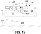
- the holding mechanism 120 of a holding device 105 includes a slide portion 123 in addition to the rotating portion 121 and the holding arm 122.
- the rotating portion 121 is a long structure extending in a predetermined direction.
- the holding arm 122 is not directly disposed with respect to the rotating portion 121.
- the slide portion 123 is a long structure extending in the same direction as the rotating portion 121.
- the slide portion 123 is supported by the rotating portion 121 to be slidable along the extending direction of the rotating portion 121.
- the holding arm 122 is disposed at a plurality of locations along the extending direction the slide portion 123. Accordingly, the long aquatic structure 200 can be stably held at a plurality of locations.
- a total of three holding arms 122 are provided: two hold the structure body 220, and one holds the foundation 210.
- the slide portion 123 is slid with respect to the rotating portion 121 such that the center of gravity G of the aquatic structure 200 detached from the water bottom 303 is positioned directly above the support shaft 121a.
- the slide portion 123 is slid to the water bottom 303 side of the holding mechanism 120 being tilted.
- the holding mechanism 120 of the holding device 105 includes the slide portion 123 in addition to the rotating portion 121 and the holding arm 122, the center of gravity G of the aquatic structure 200 can be positioned directly above the support shaft 121a while the aquatic structure 200 is tilted. Accordingly, the aquatic structure 200 can be safely tilted over.
- the rotational speed of the holding mechanism 120 can be slowed down, and the output of the drive unit (not illustrated) required for rotating the holding mechanism 120 can be reduced.
- a large-sized aquatic structure 200 can be also disassembled.
- the supporting mechanism 130 according to the second embodiment may be applied to the holding devices 103, 104, and 105
- the winch 140 according to the third embodiment may be applied to the holding devices 102, 104, and 105
- the counterweight 150 according to the fourth embodiment may be applied to the holding devices 102, 103, and 105
- the holding mechanism 120 according to the fifth embodiment may be applied to the holding devices 102, 103, and 104.
- a holding device (101, 102, 103, 104, or 105) is a holding device for holding a bottom-mounted aquatic structure (200) extending from a water bottom (303) to above the water, and includes a floating body (110) floating on the water, a holding portion (120) configured to hold the aquatic structure, and a supporting portion (130) disposed at the floating body and configured to rotatably support the aquatic structure about an axis (121a). The holding portion is rotated such that the aquatic structure is tilted over.
- the holding device includes the floating body floating on the water, the holding portion configured to hold the aquatic structure, and the supporting portion disposed at the floating body and configured to rotatably support the holding portion about the axis, and the holding portion is rotated such that the aquatic structure is tilted over.
- the aquatic structure extending in the vertical direction can be detached from the water bottom and laid down on the floating body while being held by the holding portion.
- the aquatic structure can be detached from the water bottom in a stable state, and the cut aquatic structure can be stably tilted over and laid down on the floating body.
- the aquatic structure can be moved to land in a stable state, and then disassembled on land.
- the aquatic structure can be detached from the water bottom and disassembled without posing a danger to neighboring ships or the like and without causing contaminants attached to the aquatic structure and contaminants contained in the aquatic structure to scatter or flow out into water.
- Examples of the aquatic structure include a meteorological tower, a leg structure of an offshore facility, a lighthouse, a power transmission tower, and a windmill.
- Examples of the contaminants include broken pieces of the aquatic structure, dust, and oil.
- a holding device includes a drive unit configured to rotate the holding portion rotatably supported by the supporting portion.
- the holding device includes the drive unit configured to rotate the holding portion rotatably supported by the supporting portion, and thus the holding portion holding the aquatic structure detached from the water bottom can be freely rotated about the axis.
- the drive unit includes, for example, an electric motor, and a reducer including a plurality of gears.
- the supporting portion can release the rotatable support of the holding portion to detach the holding portion.
- the supporting portion can release the rotatable support of the holding portion to detach the holding portion, and thus the mechanical connection between the floating body and the holding portion can be temporarily released.
- the rocking motions of the floating body can be prevented from being transmitted to the holding portion.
- the aquatic structure can be safely detached from the water bottom even when the floating body is rocking.
- the floating body can be prevented from being rocked by the vibration of the holding portion.
- a holding device (103) includes a towing means (140) including a wire (142) connected to the holding portion.
- the holding device includes the towing means including the wire connected to the holding portion, and thus can slow down the rotational speed of the holding portion and reduce the output of the drive unit (a motor or the like) required for rotating the holding portion.
- the towing means including the wire connected to the holding portion, and thus can slow down the rotational speed of the holding portion and reduce the output of the drive unit (a motor or the like) required for rotating the holding portion.
- a holding device (104) includes a counterweight (150) disposed at the holding portion.
- the holding device includes the counterweight disposed at the holding portion, and thus can control the position of a combined center of gravity of the aquatic structure and the holding portion.
- the aquatic structure can be safely tilted over.
- the rotational speed of the holding portion can be slowed down, and the output of the drive unit (a motor or the like) required for rotating the holding portion can be reduced.
- the weight of the counterweight can be changed by pouring and draining water.
- the weight of the counterweight can be changed by pouring and draining water, and thus the position of the center of gravity can be controlled instantaneously while the aquatic structure is being tilted.
- the aquatic structure can be safely tilted over.
- the rotational speed of the holding portion can be slowed down, and the output of the drive unit (a motor or the like) required for rotating the holding portion can be reduced.
- the holding portion includes a rotating portion (121) rotatably supported by the supporting portion, and a slide portion (123) slidably supported with respect to the rotating portion and configured to hold the aquatic structure.
- the holding portion includes the rotating portion rotatably supported by the supporting portion and the slide portion slidably supported with respect to the rotating portion and configured to hold the aquatic structure, and thus the center of gravity of the aquatic structure can be positioned directly above the axis while the aquatic structure is being tilted.
- the aquatic structure can be safely tilted over.
- the rotational speed of the holding portion can be slowed down, and the output of the drive unit (a motor or the like) required for rotating the holding portion can be reduced.
- a disassembly method is a disassembly method for disassembling a bottom-mounted type aquatic structure using a holding device including a floating body floating on water, a holding portion configured to hold the aquatic structure, and a supporting portion disposed at the floating body and configured to rotatably support the holding portion about an axis, and includes steps of holding the aquatic structure with the holding portion, detaching the aquatic structure held by the holding portion from a bottom of water, and tilting the aquatic structure by rotating the holding portion holding the aquatic structure detached from the bottom of water about the axis on the floating body.
- the rotatable support of the holding portion by the supporting portion is released after the step of holding and before the step of cutting, and the holding portion is rotatably supported by the supporting portion immediately before the aquatic structure is detached from the bottom of water in the step of cutting.
- the holding device includes a counterweight disposed at the holding portion, and the weight of the counterweight is controlled in the step of tilting.
- a counterweight is disposed at the aquatic structure, and the weight of the counterweight is controlled in the step of tilting.
- the holding portion includes a rotating portion rotatably supported by the supporting portion, and a slide portion slidably supported with respect to the rotating portion and configured to hold the aquatic structure.
- the slide portion is slid with respect to the rotating portion such that the center of gravity of the aquatic structure is positioned directly above an axis.
- the aquatic structure is detached from the water bottom by cutting an underwater portion of the aquatic structure in the step of cutting.
Landscapes
- Engineering & Computer Science (AREA)
- Mechanical Engineering (AREA)
- Transportation (AREA)
- Chemical & Material Sciences (AREA)
- Combustion & Propulsion (AREA)
- Ocean & Marine Engineering (AREA)
- General Engineering & Computer Science (AREA)
- Civil Engineering (AREA)
- Structural Engineering (AREA)
- Working Measures On Existing Buildindgs (AREA)
- Placing Or Removing Of Piles Or Sheet Piles, Or Accessories Thereof (AREA)
- Cleaning Or Clearing Of The Surface Of Open Water (AREA)
Abstract
Description
- The present disclosure relates to a holding device and a disassembly method for an aquatic structure.
- For example, in disassembling a land structure extending in the vertical direction such as a tower-type structure, an inexpensive disassembly method avoiding high-place work as much as possible may include a method in which the root of the structure is cut to topple the structure before disassembling the structure (as in
Patent Document 1, for example). The structure is cut by using, for example, explosives or other mechanical cutting methods. - Patent Document 1:
JP 4828314 B - However, when such a disassembly method is applied to a bottom-mounted aquatic structure, there is a possibility that (1) waves on the water surface generated when the structure falls down may pose a danger to surrounding ships or the like, (2) contaminants attached to the structure (e.g., broken pieces of the structure, dust, and oil) and contaminants contained in the structure may scatter or flow out into the water when and after the structure falls down and become a source of pollution, and/or (3) the fallen structure may sink into the water and cannot be recovered.
- The present disclosure has been made in view of such circumstances, and an object of the present disclosure is to provide a holding device and a disassembly method by which an aquatic structure can be detached from the bottom of water before disassembly without posing a danger to surroundings and without causing contaminants attached to the aquatic structure and contaminants contained in the aquatic structure to scatter or flow out into water.
- In order to solve the problems described above, the holding device and the disassembly method of the present disclosure adopt the following means.
- A holding device according to one aspect of the present disclosure is a holding device for holding a bottom-mounted type aquatic structure extending from a bottom of water to above the water, and includes a floating body floating on the water, a holding portion configured to hold the aquatic structure, and a supporting portion disposed at the floating body and configured to rotatably support the holding portion about an axis. The holding portion is rotated so as to tilt over the aquatic structure.
- A disassembly method according to one aspect of the present disclosure is a disassembly method for disassembling a bottom-mounted type aquatic structure using a holding device including a floating body floating on water, a holding portion configured to hold the aquatic structure, and a supporting portion disposed at the floating body and configured to rotatably support the holding portion about an axis, and includes steps of holding the aquatic structure with the holding portion, detaching the aquatic structure held by the holding portion from a bottom of water, and tilting the aquatic structure by rotating the holding portion holding the aquatic structure detached from the bottom of water about the axis on the floating body.
- According to the present disclosure, an aquatic structure can be detached from the bottom of water and disassembled without posing a danger to surroundings and without causing contaminants attached to the aquatic structure and contaminants contained in the aquatic structure to scatter or flow out into water.
-
-
FIG. 1 is a diagram illustrating states before and after the removal of an aquatic structure. -
FIG. 2 is a side view illustrating a state before a tilting step in a holding device according to a first embodiment of the present invention. -
FIG. 3 is a plan view illustrating a state before the tilting step in the holding device according to the first embodiment of the present invention. -
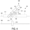
FIG. 4 is a side view illustrating a state during the tilting step in the holding device according to the first embodiment of the present invention. -
FIG. 5 is a side view illustrating a state after the tilting step in the holding device according to the first embodiment of the present invention. -
FIG. 6 is a side view illustrating a state during a holding step in a holding device according to a second embodiment of the present invention. -
FIG. 7 is a plan view illustrating a state during the holding step in the holding device according to the second embodiment of the present invention. -
FIG. 8 is a side view illustrating a state during a cutting operation in the holding device according to the second embodiment of the present invention. -
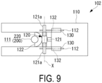
FIG. 9 is a plan view illustrating a state during the cutting operation in the holding device according to the second embodiment of the present invention. -
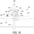
FIG. 10 is a side view illustrating a state before a tilting step in a holding device according to a third embodiment of the present invention. -
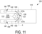
FIG. 11 is a plan view illustrating a state before the tilting step in the holding device according to the third embodiment of the present invention. -
FIG. 12 is a side view illustrating a state during a tilting step in a holding device according to a fourth embodiment of the present invention. -
FIG. 13 is a partially enlarged view of the vicinity of a counterweight in the holding device according to the fourth embodiment of the present invention. -
FIG. 14 is a side view illustrating a state during a tilting step in a holding device according to a fifth embodiment of the present invention. -
FIG. 15 is a side view illustrating a state after the tilting step in the holding device according to the fifth embodiment of the present invention. - As illustrated in
FIG. 1 , a holding device and a disassembly method according to each embodiment of the present disclosure are a device and a method used in disassembling anaquatic structure 200. - Note that "disassembling" here means not an operation of disassembling the
aquatic structure 200 itself, but an operation of detaching theaquatic structure 200 from awater bottom 303 and making theaquatic structure 200 ready for transfer from an installation location. - The
aquatic structure 200 is a bottom-mounted structure extending from thewater bottom 303 to above the water when mounted on thewater bottom 303. - Specifically, the
aquatic structure 200 is a bottom-mounted structure extending in the vertical direction (that is, having a longitudinal direction along the vertical direction) when mounted on thewater bottom 303. - Examples of the
aquatic structure 200 include a meteorological tower, a leg structure for an offshore facility, a lighthouse, a power transmission tower, and a windmill for power generation. - The
aquatic structure 200 includes afoundation 210 and astructure body 220. - The
foundation 210 extends in the vertical direction and a lower portion of thefoundation 210 is driven into thewater bottom 303. Thefoundation 210 may be a jacket-type foundation, a tripot-type foundation, or a tripile-type foundation, in addition to the illustrated monopile-type foundation. The specific form of the structure of thefoundation 210 is not limited as long as thefoundation 210 is a bottom-mounted type foundation. - The
structure body 220 is provided at an upper portion of thefoundation 210 in the vertical direction, and a portion including an upper end of thestructure body 220 is exposed above awater surface 301. - The
structure body 220 is a part that performs the substantial function of theaquatic structure 200. Since thestructure body 220 includes equipment necessary for performing this function, the weight of thestructure body 220 is often heavier than the weight of thefoundation 210. - Note that in the
aquatic structure 200, a boundary between thefoundation 210 and thestructure body 220 need not be clearly delimited. - In the following, a holding device and a disassembly method will be described in detail using a plurality of embodiments as examples.
- A holding device and a disassembly method according to a first embodiment of the present disclosure will be described below with reference to
FIGS. 2 to 5 . - As illustrated in
FIG. 2 andFIG. 3 , aholding device 101 includes a floating body structure (floating body) 110, a holding mechanism (holding portion) 120, and a supporting mechanism (supporting portion) 130. - The
floating body structure 110 is a part that floats in water (on water) by a buoyant force. Thefloating body structure 110 is designed to generate a sufficient buoyant force so as not to sink even when the entire weight of the disassembledaquatic structure 200 is applied. - As illustrated in
FIG. 3 , thefloating body structure 110 includes arecess 111 extending in a predetermined direction. Due to therecess 111, thefloating body structure 110 has a U-shape in a plan view. - As illustrated in
FIG. 2 andFIG. 3 , therecess 111 is a space or a gap into which theaquatic structure 200 and theholding mechanism 120 enter when theaquatic structure 200 is disassembled. - Note that the
floating body structure 110 is not limited to the above-described configuration (U-shape). For example, the configuration of thefloating body structure 110 may be changed by providing a mechanism configured to open and close an opening of therecess 111 such that the opening of therecess 111 is closed when thefloating body structure 110 is in transit and the opening opens when theaquatic structure 200 is tilted. - Two supporting
mechanisms 130 are disposed at an upper surface of thefloating body structure 110. - The two supporting
mechanisms 130 are disposed opposing each other across therecess 111. - The supporting
mechanism 130 is a part that rotatably supports asupport shaft 121a included in theholding mechanism 120. - The
holding mechanism 120 is a part that holds and grips theaquatic structure 200. - As illustrated in
FIG. 3 , theholding mechanism 120 is disposed between the supportingmechanisms 130 that oppose each other. - As illustrated in
FIG. 2 andFIG. 3 , theholding mechanism 120 includes a rotatingportion 121 and aholding arm 122. - The rotating
portion 121 is a long structure extending in a predetermined direction. - The rotating
portion 121 includes thesupport shaft 121a having an axis of rotation (axis) X along the horizontal direction. Thesupport shaft 121a protrudes on both sides of therotating portion 121. - The
support shaft 121a of therotating portion 121 is supported by the supportingmechanisms 130. Accordingly, the rotatingportion 121 and thus theholding mechanism 120 are rotatably supported by the supportingmechanisms 130. - The holding
arm 122 is a mechanism that holds and grips theaquatic structure 200. - The holding
arm 122 is provided at a plurality of locations along an extending direction of therotating portion 121. Accordingly, the longaquatic structure 200 can be stably held at a plurality of locations. In the case ofFIG. 2 , a total of three holdingarms 122 are provided: two hold thestructure body 220, and one holds thefoundation 210. - Note that the holding
arm 122 and therotating portion 121 may be configured such that the holdingarm 122 moves in the extending direction of therotating portion 121 according to the dimension (height) of theaquatic structure 200. - As illustrated in
FIG. 2 , when theholding mechanism 120 holds/is holding theaquatic structure 200, an extending direction of the holding mechanism 120 (that is, the extending direction of the rotating portion 121) coincides with an extending direction of theaquatic structure 200. - For example, when the
holding mechanism 120 holds/is holding theaquatic structure 200, which is driven into thewater bottom 303 and extends in the vertical direction, the extending direction of theholding mechanism 120 coincides with the vertical direction, similar to theaquatic structure 200. - At this time, the
holding mechanism 120 is disposed between the supportingmechanisms 130, and a lower portion of theholding mechanism 120 is located in therecess 111. - On the other hand, when the
holding mechanism 120 is not holding theaquatic structure 200, the extending direction of theholding mechanism 120 need not coincide with the extending direction of theaquatic structure 200, and theholding mechanism 120 may be positioned such that the extending direction of theholding mechanism 120 coincides with the horizontal direction, for example. - The time when the
holding mechanism 120 is not holding theaquatic structure 200 refers to, for example, a time when the holdingdevice 101 is transferred to the vicinity of theaquatic structure 200 before the start of a disassembling operation. - In the
holding device 101 configured as described above, theholding mechanism 120 rotatably supported by the supportingmechanisms 130 is rotated about the axis of rotation X of thesupport shaft 121a by a drive unit (not illustrated). - The drive unit includes, for example, an electric motor and a reducer including a plurality of gears.
- First, as illustrated in
FIG. 2 andFIG. 3 , the holdingdevice 101 is moved such that theaquatic structure 200 enters therecess 111 of the floatingbody structure 110. - The holding
device 101 is moved by, for example, towing by a ship. Alternatively, the holdingdevice 101 may be provided with power so as to be self-propelled. - Next, the angle of the
holding mechanism 120 is controlled such that the extending direction of theholding mechanism 120 coincides with the extending direction of theaquatic structure 200. - This angle is controlled by using the drive unit described above.
- Next, the
aquatic structure 200 is held by the holdingarms 122 of the holding mechanism 120 (holding step). Accordingly, theaquatic structure 200 is secured to theholding mechanism 120. - Next, as illustrated in
FIG. 2 , a cutting operation of cutting thefoundation 210 of theaquatic structure 200 is started. - During cutting, contamination control measures such as covering a portion of the
foundation 210, which has acut surface 211, with a cover may be taken. - Preferably, the position of the
cut surface 211 is as close to thewater bottom 303 as possible. - The reason for this is as follows. Ordinarily, the weight of the
structure body 220 is heavier than the weight of thefoundation 210, and the position of the center of gravity G of theaquatic structure 200 tends to be located above the axis of rotation X in the vertical direction. Thus, the position of thecut surface 211 has been contrived such that the center of gravity G of theaquatic structure 200 after being detached from thewater bottom 303 is located as close to the axis of rotation X as possible to reduce the torque required for rotating theholding mechanism 120. - Note that the cutting operation of the
foundation 210 may be started before the holding step, and theaquatic structure 200 may be held by theholding mechanism 120 in the middle of the cutting operation. In short, theaquatic structure 200 only needs to be held by theholding mechanism 120 before theaquatic structure 200 is completely detached from thewater bottom 303. - Next, the cutting operation of the
aquatic structure 200 is completed, and theaquatic structure 200 held by theholding mechanism 120 is completely detached from the water bottom 303 (cutting step). Accordingly, the system of the holdingdevice 101 holding theaquatic structure 200 is completely separated from thewater bottom 303. - Next, as illustrated in
FIG. 4 , theholding mechanism 120 is rotated by using the drive unit (not illustrated) so as to tilt theaquatic structure 200 in a direction along which a cut end of theaquatic structure 200 passes through the recess 111 (a direction in which the cut end is lifted up) (tilting step). - At this time, preferably, the
holding mechanism 120 is rotated by the drive unit at a low speed in order to safely tilt theaquatic structure 200. - Finally, as illustrated in
FIG. 5 , theaquatic structure 200 is tilted until theaquatic structure 200 is placed on the floatingbody structure 110 with the extending direction of theaquatic structure 200 coincident with the horizontal direction. - Since the system of the holding
device 101 including theaquatic structure 200 is completely separated from thewater bottom 303 in a state where theaquatic structure 200 is laid down, theaquatic structure 200 can be moved to the vicinity of land together with the holdingdevice 101. - Then, the
aquatic structure 200 placed on theholding device 101 is pulled up to land by, for example, a crane installed on land, so that theaquatic structure 200 can be safely disassembled on land. - According to the present embodiment, the following effects are obtained.
- That is, the holding
device 101 includes the floatingbody structure 110 floating on the water, theholding mechanism 120 configured to hold theaquatic structure 200, and the supportingmechanisms 130 disposed at the floatingbody structure 110 and configured to rotatably support theholding mechanism 120 about an axis. Theholding mechanism 120 is rotated such that theaquatic structure 200 is tilted, and thus, for example, theaquatic structure 200 extending in the vertical direction can be detached from thewater bottom 303 and laid down on the floatingbody structure 110 while being held by theholding mechanism 120. - Thus, the
aquatic structure 200 can be detached from thewater bottom 303 in a stable state, and the detachedaquatic structure 200 can be stably tilted and laid down on the floatingbody structure 200. In addition, for example, by placing theaquatic structure 200 on the floatingbody structure 110 in a laid-down state, theaquatic structure 200 can be moved to land in a stable state, and then disassembled on land. - Accordingly, the
aquatic structure 200 can be detached from thewater bottom 303 and disassembled without posing a danger to neighboring ships or the like and without causing contaminants attached to theaquatic structure 200 and contaminants contained in theaquatic structure 200 to scatter or flow out into water. - In addition, when the holding
device 101 includes a drive unit configured to rotate theholding mechanism 120 rotatably supported by the supportingmechanisms 130, theholding mechanism 120 holding theaquatic structure 200 detached from thewater bottom 303 can be freely rotated about the axis. - Next, a holding device and a disassembly method according to a second embodiment of the present disclosure will be described below with reference to
FIGS. 6 to 9 . - Note that the holding device and the disassembly method according to the present embodiment differ from those of the first embodiment in the structure of the floating
body structure 110 and the structure of the supportingmechanism 130, but are identical to those of the first embodiment in other respects. Therefore, the same components are denoted by the same reference signs, and description thereof will be omitted. - Note that the holding device denoted by the
reference sign 101 in the first embodiment is denoted by thereference sign 102 in the present embodiment. - As illustrated in
FIGS. 6 to 9 , in aholding device 102, the supportingmechanism 130 is configured to temporarily release the rotatable support of thesupport shaft 121a. - This configuration will be described in detail below.
- As illustrated in
FIG. 6 andFIG. 7 ,wheels 132 are provided at a lower portion of the supportingmechanism 130. Also, tworails 112 are laid parallel on the floatingbody structure 110. - The supporting
mechanisms 130 are placed movably along therails 112 on the floatingbody structure 110 via thewheels 132. - A supporting
cutout 131 is formed in the supportingmechanism 130. - The supporting
cutout 131 is a U-shaped cutout extending in the horizontal direction. A semi-circular arc-shaped end of the supportingcutout 131 corresponds to the shape of thesupport axis 121a. - When the
support shaft 121a is held by the supportingcutout 131, thesupport shaft 121a is rotatably supported by the supportingmechanism 130. - As illustrated in
FIG. 8 andFIG. 9 , when the supportingmechanisms 130 are moved along therails 112, the supportingcutouts 131 also move, and thus thesupport shaft 121a is disengaged from the supportingcutouts 131. - This means that the supporting
mechanisms 130 release the rotatable support of thesupport shaft 121a. That is, the supportingmechanisms 130 and theholding mechanism 120 are mechanically separated. - When the supporting
mechanisms 130 and theholding mechanism 120 are mechanically separated, the system of theholding mechanism 120 holding theaquatic structure 200 is separated from the system of the floatingbody structure 110 including the supportingmechanisms 130. - Accordingly, rocking motions of the floating
body structure 110 can be prevented from being transmitted to theholding mechanism 120, and vibrations of theholding mechanism 120 can be prevented from being transmitted to the floatingbody structure 110. - Note that each inside surface of the recess 111 (three surfaces in total) may be provided with a cushioning
member 113 protruding toward the holding mechanism 120 (rotating portion 121). - Examples of the material of the cushioning
member 113 include a rubber material such as chloroprene, and a rubber material that is commercially-available as a fender. In addition, mechanical shock absorbing means such as a hydraulic damper or a metal spring can be used, or can be used in combination with the cushioningmember 113. - The cushioning
member 113 is disposed with a slight gap from the rotatingportion 121, or is disposed in slight contact with therotating portion 121. - Accordingly, the system of the
holding mechanism 120 is lightly secured to the system of the floatingbody structure 110 even after the supportingmechanism 130 releases the rotatable support of thesupport shaft 121a. Thus, the system of theholding mechanism 120 and the system of the floatingbody structure 110 can be prevented from being easily separated from each other by the effect of wind or waves, for example. In addition, vibrations between the respective systems are mitigated by thecushioning members 113. - First, as illustrated in
FIG. 6 andFIG. 7 , the steps up to the holding step are similar to those in the first embodiment. Accordingly, theaquatic structure 200 is secured to theholding mechanism 120. - Next, as illustrated in
FIG. 8 andFIG. 9 , the supportingmechanisms 130 are moved along therails 112 to release the rotatable support of theholding mechanism 120. - Next, a cutting operation of cutting the
foundation 210 of theaquatic structure 200 is started. - At this time, since the system of the
holding mechanism 120 holding theaquatic structure 200 and the system of the floatingbody structure 110 including the supportingmechanisms 130 are separated from each other, rocking motions of the floatingbody structure 110 are not transmitted to theholding mechanism 120, and vibrations of theholding mechanism 120 are not transmitted to the floatingbody structure 110. Accordingly, the cutting operation can be performed safely. - When the cutting operation proceeds until just before the
aquatic structure 200 is completely detached from thewater bottom 303, it is confirmed that the rocking motions of the floatingbody structure 110 are small enough not to affect the cutting operation, and then the supportingmechanisms 130 are moved along therails 112 to rotatably support theholding mechanism 120, as illustrated inFIG. 6 andFIG. 7 . - Next, the cutting operation of the
aquatic structure 200 is completed, and theaquatic structure 200 held by theholding mechanism 120 is completely detached from the water bottom 303 (cutting step). Accordingly, the system of the holdingdevice 101 holding theaquatic structure 200 is completely separated from thewater bottom 303. - The steps after the cutting step are similar to those in the first embodiment, and thus descriptions thereof are omitted.
- According to the present embodiment, the following effect is obtained.
- Since the supporting
mechanisms 130 can release the rotatable support of theholding mechanism 120 to detach theholding mechanism 120, the mechanical connection between the floatingbody structure 110 and theholding mechanism 120 can be temporarily released. Accordingly, the rocking motions of the floatingbody structure 110 can be prevented from being transmitted to theholding mechanism 120. Thus, theaquatic structure 200 can be safely detached from thewater bottom 303. - Next, a holding device and a disassembly method according to a third embodiment of the present disclosure will be described below with reference to
FIG. 10 andFIG. 11 . - Note that the holding device and the disassembly method according to the present embodiment include a winch (towing means) 140 and differ in this respect from the first embodiment and the second embodiment, but are identical the first embodiment and the second embodiment in other respects. Therefore, the same components are denoted by the same reference signs, and description thereof will be omitted.
- Note that the holding device denoted by the
reference sign 101 in the first embodiment is denoted by thereference sign 103 in the present embodiment. - As illustrated in
FIG. 10 andFIG. 11 , the holdingdevice 103 includes thewinch 140 including awinch body 141 and awire 142. - The
winch body 141 is a part that reels in/out thewire 142. - The
winch body 141 is disposed at an upper surface of the floatingbody structure 110. - Two
winch bodies 141 are disposed opposing each other across therecess 111 at a leading end side of the floatingbody structure 110. - One end of the
wire 142 is connected to thewinch body 141. - The other end of the
wire 142 is connected to aconnection point 121b of therotating portion 121. When theholding mechanism 120 extends in the vertical direction, theconnection point 121b is located above thesupport shaft 121a in the vertical direction. - A
pulley 143 is disposed between thewinch body 141 and theconnection point 121b and above theconnection point 121b in the vertical direction. The position of thepulley 143 is fixed with respect to the floatingbody structure 110. - The
wire 142 is hooked onto thepulley 143. That is, thewire 142 exerts tension between thewinch body 141 and therotating portion 121 with thepulley 143 as an apex. - According to the present embodiment, the following effect is obtained.
- Since the holding
device 103 includes thewinch 140, the holdingdevice 130 can slow down the rotational speed of theholding mechanism 120 and reduce the output of the drive unit (not illustrated) required for rotating theholding mechanism 120. - Note that the drive unit may be omitted, and the orientation of the
holding mechanism 120 may be changed by thewinch 140 only. - Next, a holding device and a disassembly method according to a fourth embodiment of the present disclosure will be described below with reference to
FIG. 12 andFIG. 13 . - Note that the holding device and the disassembly method according to the present embodiment include a
counterweight 150 and differ in this respect from the first to the third embodiments, but are identical to the first to the third embodiments in other respects. Therefore, the same components are denoted by the same reference signs, and description thereof will be omitted. - Note that the holding device denoted by the
reference sign 101 in the first embodiment is denoted by thereference sign 104 in the present embodiment. - As illustrated in
FIG. 12 andFIG. 13 , the holdingdevice 104 includes thecounterweight 150 including aballast tank 151. - The
counterweight 150 is disposed at an end portion of therotating portion 121 located on thefoundation 210 side of theaquatic structure 200. - As illustrated in
FIG. 13 , theballast tank 151 has a space formed inside and is configured such that water can be poured into and drained from the space. - Water is poured and drained by, for example, a pump (not illustrated). With this configuration, the weight of the
counterweight 150 can be changed. - Note that the
counterweight 150 excluding theballast tank 151 may be a simple mass body (for example, a concrete mass or a metal mass). - Preferably, the
ballast tank 151 is disposed facing upward in the vertical direction as theaquatic structure 200 is tilted. - Water may be drained from the
ballast tank 151 by gravity instead of a pump (not illustrated). Specifically, theballast tank 151 may be provided with a drainage hole to cause water to naturally flow out from the drainage hole as theaquatic structure 200 is tilted. - According to the present embodiment, the following effects are obtained.
- Since the holding
device 104 includes thecounterweight 150 disposed at theholding mechanism 120, the holdingdevice 104 can control the position of a combined center of gravity of theaquatic structure 200 and theholding mechanism 120. Accordingly, theaquatic structure 200 can be safely tilted over. - Further, since the weight of the
counterweight 150 can be changed by pouring and draining water, the position of the combined center of gravity can be controlled instantaneously while theaquatic structure 200 is being tilted. Accordingly, theaquatic structure 200 can be safely tilted over. - In addition, the rotational speed of the
holding mechanism 120 can be slowed down, and the output of the drive unit (not illustrated) required for rotating theholding mechanism 120 can be reduced. - Note that the
counterweight 150 may be disposed at the aquatic structure 200 (for example, at an end portion of the foundation 210) instead of at therotating portion 121, or may be disposed at both theaquatic structure 200 and therotating portion 121. - Next, a holding device and a disassembly method according to a fifth embodiment of the present disclosure will be described below with reference to
FIG. 14 andFIG. 15 . - Note that the holding device and the disassembly method according to the present embodiment differ from the first to the fourth embodiments in the structure of the
holding mechanism 120, but are identical to the first to the fourth embodiments in other respects. Therefore, the same components are denoted by the same reference signs, and description thereof will be omitted. - Note that the holding device denoted by the
reference sign 101 in the first embodiment is denoted by thereference sign 105 in the present embodiment. - As illustrated in
FIG. 14 , theholding mechanism 120 of aholding device 105 includes aslide portion 123 in addition to therotating portion 121 and the holdingarm 122. - As in the first to fourth embodiments, the rotating
portion 121 is a long structure extending in a predetermined direction. - However, unlike the first to fourth embodiments, the holding
arm 122 is not directly disposed with respect to therotating portion 121. - The
slide portion 123 is a long structure extending in the same direction as the rotatingportion 121. - The
slide portion 123 is supported by the rotatingportion 121 to be slidable along the extending direction of therotating portion 121. - The holding
arm 122 is disposed at a plurality of locations along the extending direction theslide portion 123. Accordingly, the longaquatic structure 200 can be stably held at a plurality of locations. In the case ofFIG. 14 , a total of three holdingarms 122 are provided: two hold thestructure body 220, and one holds thefoundation 210. - The steps up to the cutting step are similar to those in the first embodiment, and thus descriptions thereof are omitted.
- As illustrated in
FIG. 14 andFIG. 15 , in the tilting step, theslide portion 123 is slid with respect to therotating portion 121 such that the center of gravity G of theaquatic structure 200 detached from thewater bottom 303 is positioned directly above thesupport shaft 121a. In the case of these drawings, theslide portion 123 is slid to thewater bottom 303 side of theholding mechanism 120 being tilted. - According to the present embodiment, the following effects are obtained.
- Since the
holding mechanism 120 of the holdingdevice 105 includes theslide portion 123 in addition to therotating portion 121 and the holdingarm 122, the center of gravity G of theaquatic structure 200 can be positioned directly above thesupport shaft 121a while theaquatic structure 200 is tilted. Accordingly, theaquatic structure 200 can be safely tilted over. - In addition, the rotational speed of the
holding mechanism 120 can be slowed down, and the output of the drive unit (not illustrated) required for rotating theholding mechanism 120 can be reduced. - Note that, when the
slide portion 123 is configured to extend in the extending direction thereof, a large-sizedaquatic structure 200 can be also disassembled. - The embodiments described above can be combined as appropriate.
- For example, the supporting
mechanism 130 according to the second embodiment may be applied to the holdingdevices winch 140 according to the third embodiment may be applied to the holdingdevices counterweight 150 according to the fourth embodiment may be applied to the holdingdevices holding mechanism 120 according to the fifth embodiment may be applied to the holdingdevices - The holding devices and the disassembly methods according to the embodiments described above can be understood, for example, as follows.
- A holding device (101, 102, 103, 104, or 105) according to one aspect of the present disclosure is a holding device for holding a bottom-mounted aquatic structure (200) extending from a water bottom (303) to above the water, and includes a floating body (110) floating on the water, a holding portion (120) configured to hold the aquatic structure, and a supporting portion (130) disposed at the floating body and configured to rotatably support the aquatic structure about an axis (121a). The holding portion is rotated such that the aquatic structure is tilted over.
- The holding device according to the present aspect includes the floating body floating on the water, the holding portion configured to hold the aquatic structure, and the supporting portion disposed at the floating body and configured to rotatably support the holding portion about the axis, and the holding portion is rotated such that the aquatic structure is tilted over. Thus, for example, the aquatic structure extending in the vertical direction can be detached from the water bottom and laid down on the floating body while being held by the holding portion. Accordingly, the aquatic structure can be detached from the water bottom in a stable state, and the cut aquatic structure can be stably tilted over and laid down on the floating body. In addition, for example, by placing the aquatic structure, which has extended in the vertical direction, on the floating body in a laid-down state, the aquatic structure can be moved to land in a stable state, and then disassembled on land.
- Accordingly, the aquatic structure can be detached from the water bottom and disassembled without posing a danger to neighboring ships or the like and without causing contaminants attached to the aquatic structure and contaminants contained in the aquatic structure to scatter or flow out into water.
- Examples of the aquatic structure include a meteorological tower, a leg structure of an offshore facility, a lighthouse, a power transmission tower, and a windmill.
- Examples of the contaminants include broken pieces of the aquatic structure, dust, and oil.
- A holding device according to one aspect of the present disclosure includes a drive unit configured to rotate the holding portion rotatably supported by the supporting portion.
- The holding device according to the present aspect includes the drive unit configured to rotate the holding portion rotatably supported by the supporting portion, and thus the holding portion holding the aquatic structure detached from the water bottom can be freely rotated about the axis.
- The drive unit includes, for example, an electric motor, and a reducer including a plurality of gears.
- In a holding device (102) according to one aspect of the present disclosure, the supporting portion can release the rotatable support of the holding portion to detach the holding portion.
- In the holding device according to the present aspect, the supporting portion can release the rotatable support of the holding portion to detach the holding portion, and thus the mechanical connection between the floating body and the holding portion can be temporarily released.
- Accordingly, the rocking motions of the floating body can be prevented from being transmitted to the holding portion. Thus, the aquatic structure can be safely detached from the water bottom even when the floating body is rocking. On the other hand, even when the holding portion vibrates, the floating body can be prevented from being rocked by the vibration of the holding portion.
- A holding device (103) according to one aspect of the present disclosure includes a towing means (140) including a wire (142) connected to the holding portion.
- The holding device according to the present aspect includes the towing means including the wire connected to the holding portion, and thus can slow down the rotational speed of the holding portion and reduce the output of the drive unit (a motor or the like) required for rotating the holding portion.
- A holding device (104) according to one aspect of the present disclosure includes a counterweight (150) disposed at the holding portion.
- The holding device according to the present aspect includes the counterweight disposed at the holding portion, and thus can control the position of a combined center of gravity of the aquatic structure and the holding portion.
- Accordingly, the aquatic structure can be safely tilted over. In addition, the rotational speed of the holding portion can be slowed down, and the output of the drive unit (a motor or the like) required for rotating the holding portion can be reduced.
- In a holding device according to one aspect of the present disclosure, the weight of the counterweight can be changed by pouring and draining water.
- In the holding device according to the present aspect, the weight of the counterweight can be changed by pouring and draining water, and thus the position of the center of gravity can be controlled instantaneously while the aquatic structure is being tilted.
- Accordingly, the aquatic structure can be safely tilted over. In addition, the rotational speed of the holding portion can be slowed down, and the output of the drive unit (a motor or the like) required for rotating the holding portion can be reduced.
- In a holding device (105) according to one aspect of the present disclosure, the holding portion includes a rotating portion (121) rotatably supported by the supporting portion, and a slide portion (123) slidably supported with respect to the rotating portion and configured to hold the aquatic structure.
- In the holding device according to the present aspect, the holding portion includes the rotating portion rotatably supported by the supporting portion and the slide portion slidably supported with respect to the rotating portion and configured to hold the aquatic structure, and thus the center of gravity of the aquatic structure can be positioned directly above the axis while the aquatic structure is being tilted.
- Accordingly, the aquatic structure can be safely tilted over. In addition, the rotational speed of the holding portion can be slowed down, and the output of the drive unit (a motor or the like) required for rotating the holding portion can be reduced.
- A disassembly method according to one aspect of the present disclosure is a disassembly method for disassembling a bottom-mounted type aquatic structure using a holding device including a floating body floating on water, a holding portion configured to hold the aquatic structure, and a supporting portion disposed at the floating body and configured to rotatably support the holding portion about an axis, and includes steps of holding the aquatic structure with the holding portion, detaching the aquatic structure held by the holding portion from a bottom of water, and tilting the aquatic structure by rotating the holding portion holding the aquatic structure detached from the bottom of water about the axis on the floating body.
- In a disassembly method according to one aspect of the present disclosure, the rotatable support of the holding portion by the supporting portion is released after the step of holding and before the step of cutting, and the holding portion is rotatably supported by the supporting portion immediately before the aquatic structure is detached from the bottom of water in the step of cutting.
- In a disassembly method according to one aspect of the present disclosure, the holding device includes a counterweight disposed at the holding portion, and the weight of the counterweight is controlled in the step of tilting.
- In a disassembly method according to one aspect of the present disclosure, a counterweight is disposed at the aquatic structure, and the weight of the counterweight is controlled in the step of tilting.
- In a disassembly method according to one aspect of the present disclosure, the holding portion includes a rotating portion rotatably supported by the supporting portion, and a slide portion slidably supported with respect to the rotating portion and configured to hold the aquatic structure. In the step of tilting, the slide portion is slid with respect to the rotating portion such that the center of gravity of the aquatic structure is positioned directly above an axis.
- In a disassembly method according to one aspect of the present disclosure, the aquatic structure is detached from the water bottom by cutting an underwater portion of the aquatic structure in the step of cutting.
-
- 101, 102, 103, 104, 105 Holding device
- 110 Floating body structure (floating body)
- 111 Recess
- 112 Rail
- 113 Cushioning member
- 120 Holding mechanism (holding portion)
- 121 Rotating portion
- 121a Support shaft
- 121b Connection point
- 122 Holding arm
- 123 Slide portion
- 130 Supporting mechanism (supporting portion)
- 131 Supporting cutout
- 132 Wheel
- 140 Winch (towing means)
- 141 Winch body
- 142 Wire
- 143 Pulley
- 150 Counterweight
- 151 Ballast tank
- 200 Aquatic structure
- 210 Foundation
- 211 Cut surface
- 220 Structure body
- 301 Water surface
- 303 Water bottom
Claims (13)
- A holding device for holding a bottom-mounted type aquatic structure extending from a bottom of water to above the water, the holding device comprising:a floating body floating on the water;a holding portion configured to hold the aquatic structure; anda supporting portion disposed at the floating body, the supporting portion being configured to rotatably support the holding portion about an axis,the holding portion being configured to rotate such that the aquatic structure is tilted over.
- The holding device according to claim 1, further comprising a drive unit configured to rotate the holding portion rotatably supported by the supporting portion.
- The holding device according to claim 1 or 2, wherein the supporting portion can release rotatable support of the holding portion to detach the holding portion.
- The holding device according to any one of claims 1 to 3, further comprising a towing means including a wire connected to the holding portion.
- The holding device according to any one of claims 1 to 4, further comprising a counterweight disposed at the holding portion.
- The holding device according to claim 5, wherein weight of the counterweight can be changed by pouring and draining water.
- The holding device according to any one of claims 1 to 6, wherein the holding portion comprisesa rotating portion rotatably supported by the supporting portion; anda slide portion slidably supported with respect to the rotating portion and configured to hold the aquatic structure.
- A disassembly method for disassembling a bottom-mounted type aquatic structure using a holding device including a floating body floating on water, a holding portion configured to hold the aquatic structure, and a supporting portion disposed at the floating body and configured to rotatably support the holding portion about an axis, the disassembly method comprising:holding the aquatic structure with the holding portion;detaching the aquatic structure held by the holding portion from a bottom of water; andtilting the aquatic structure by rotating the holding portion holding the aquatic structure detached from the bottom of water about the axis on the floating body.
- The disassembly method according to claim 8, whereinafter the holding and before the detaching, rotatable support of the holding portion by the supporting portion is released, andin the detaching, the holding portion is rotatably supported by the supporting portion immediately before the aquatic structure is detached from the bottom of water.
- The disassembly method according to claim 8 or 9, whereinthe holding device comprises a counterweight disposed at the holding portion, andweight of the counterweight is controlled in the tilting.
- The disassembly method according to claim 8 or 9, wherein a counterweight is disposed at the aquatic structure, and weight of the counterweight is controlled in the tilting.
- The disassembly method according to any one of claims 8 to 11, whereinthe holding portion comprises a rotating portion rotatably supported by the supporting portion, and a slide portion slidably supported with respect to the rotating portion and configured to hold the aquatic structure, andin the tilting, the slide portion is slid with respect to the rotating portion such that a center of gravity of the aquatic structure is positioned directly above the axis.
- The disassembly method according to any one of claims 8 to 12, wherein the aquatic structure is detached from the bottom of water by cutting an underwater portion of the aquatic structure in the cutting.
Applications Claiming Priority (1)
| Application Number | Priority Date | Filing Date | Title |
|---|---|---|---|
| JP2021214531A JP7753090B2 (en) | 2021-12-28 | 2021-12-28 | Disassembly method |
Publications (2)
| Publication Number | Publication Date |
|---|---|
| EP4206404A1 true EP4206404A1 (en) | 2023-07-05 |
| EP4206404B1 EP4206404B1 (en) | 2025-11-19 |
Family
ID=84688978
Family Applications (1)
| Application Number | Title | Priority Date | Filing Date |
|---|---|---|---|
| EP22211596.6A Active EP4206404B1 (en) | 2021-12-28 | 2022-12-06 | Holding device and disassembly method for aquatic structure |
Country Status (2)
| Country | Link |
|---|---|
| EP (1) | EP4206404B1 (en) |
| JP (1) | JP7753090B2 (en) |
Cited By (1)
| Publication number | Priority date | Publication date | Assignee | Title |
|---|---|---|---|---|
| CN116853431A (en) * | 2023-07-28 | 2023-10-10 | 杭州华能工程安全科技股份有限公司 | Deployment device and method of floating measuring instruments on water surface |
Citations (4)
| Publication number | Priority date | Publication date | Assignee | Title |
|---|---|---|---|---|
| NO322435B1 (en) * | 2005-01-28 | 2006-10-02 | Mpu Entpr As | Device for transporting objects to water |
| US20110119889A1 (en) * | 2008-08-28 | 2011-05-26 | Mitsubish Heavy Industies, Ltd. | Construction method and construction apparatus for offshore wind turbine generator |
| JP4828314B2 (en) | 2006-06-09 | 2011-11-30 | ベステラ株式会社 | Method of defeating steel tower supported chimney structure |
| EP3674199A1 (en) * | 2018-12-24 | 2020-07-01 | UK Decom Limited | Decommissioning of offshore structures |
Family Cites Families (5)
| Publication number | Priority date | Publication date | Assignee | Title |
|---|---|---|---|---|
| US4683832A (en) * | 1984-07-30 | 1987-08-04 | Dysarz Edward D | Device and method to set and salvage structures |
| NL191995C (en) * | 1988-10-04 | 1996-12-03 | Allseas Eng Bv | Method and device for moving a support construction of an artificial island relative to an underwater bottom. |
| JPH0841873A (en) * | 1994-07-27 | 1996-02-13 | Mitsubishi Heavy Ind Ltd | Pile driving boat |
| NL1012314C2 (en) * | 1999-06-14 | 2000-12-15 | Excalibur Engineering B V | Method for removing a substructure from a drilling or production platform and vessel provided with a device therefor. |
| JP5264853B2 (en) * | 2010-10-01 | 2013-08-14 | 第一建設機工株式会社 | Construction method of deck lifting work platform ship and offshore wind power generation facility |
-
2021
- 2021-12-28 JP JP2021214531A patent/JP7753090B2/en active Active
-
2022
- 2022-12-06 EP EP22211596.6A patent/EP4206404B1/en active Active
Patent Citations (4)
| Publication number | Priority date | Publication date | Assignee | Title |
|---|---|---|---|---|
| NO322435B1 (en) * | 2005-01-28 | 2006-10-02 | Mpu Entpr As | Device for transporting objects to water |
| JP4828314B2 (en) | 2006-06-09 | 2011-11-30 | ベステラ株式会社 | Method of defeating steel tower supported chimney structure |
| US20110119889A1 (en) * | 2008-08-28 | 2011-05-26 | Mitsubish Heavy Industies, Ltd. | Construction method and construction apparatus for offshore wind turbine generator |
| EP3674199A1 (en) * | 2018-12-24 | 2020-07-01 | UK Decom Limited | Decommissioning of offshore structures |
Cited By (1)
| Publication number | Priority date | Publication date | Assignee | Title |
|---|---|---|---|---|
| CN116853431A (en) * | 2023-07-28 | 2023-10-10 | 杭州华能工程安全科技股份有限公司 | Deployment device and method of floating measuring instruments on water surface |
Also Published As
| Publication number | Publication date |
|---|---|
| JP2023098044A (en) | 2023-07-10 |
| EP4206404B1 (en) | 2025-11-19 |
| JP7753090B2 (en) | 2025-10-14 |
Similar Documents
| Publication | Publication Date | Title |
|---|---|---|
| CN104903572B (en) | The component moving method of float type wind power generation plant and the device | |
| JP5750537B1 (en) | Offshore structure construction method | |
| JP5736133B2 (en) | Floating structure work system, work boat, and floating structure work method | |
| JP7252857B2 (en) | FLOATING STRUCTURE INSTALLATION SYSTEM AND FLOATING STRUCTURE INSTALLATION METHOD | |
| US12195305B2 (en) | Vessel and method for installation of a pile adapted to support an offshore wind turbine | |
| GB2174648A (en) | Installation and removal vessel | |
| EP2818703B1 (en) | Ship for installing offshore wind turbine and method for installing offshore wind turbine | |
| EP4206404B1 (en) | Holding device and disassembly method for aquatic structure | |
| CA2569004A1 (en) | Water current turbine with improved method of access | |
| JP5690116B2 (en) | Hydroelectric power generation equipment | |
| EP4298046A1 (en) | Arrangement of a crane on a floating wind power station | |
| CN207972752U (en) | A kind of oceanographic buoy lowering equipment | |
| CN103274023A (en) | Simple-erecting access board between offshore floats | |
| CN101337575A (en) | Anchor handling device | |
| EP4251875B1 (en) | Device and method for mounting a wind turbine component on a wind turbine tower | |
| CN203095441U (en) | Combined floating crane for mud flats | |
| JP2021151800A (en) | Construction method for floating body type on-water structure and floating body for mooring used for the same | |
| KR102735611B1 (en) | Portable anchoring device | |
| CN222022848U (en) | A semi-submersible wind power installation vessel with a fully revolving crane | |
| JP2023111211A (en) | Structure tilting method and structure for tilting | |
| JP7752215B1 (en) | Installation method | |
| JP2000265485A (en) | Sinking device for underwater structure | |
| CN216580913U (en) | Large-gradient reverse-slope drainage tunnel water pump quick-moving installation device | |
| CN118242228A (en) | Floating fan and installation method thereof | |
| KR101866972B1 (en) | Variable foundation structure of offshore support structure and construction method of offshore support structure thereof |
Legal Events
| Date | Code | Title | Description |
|---|---|---|---|
| PUAI | Public reference made under article 153(3) epc to a published international application that has entered the european phase |
Free format text: ORIGINAL CODE: 0009012 |
|
| STAA | Information on the status of an ep patent application or granted ep patent |
Free format text: STATUS: THE APPLICATION HAS BEEN PUBLISHED |
|
| AK | Designated contracting states |
Kind code of ref document: A1 Designated state(s): AL AT BE BG CH CY CZ DE DK EE ES FI FR GB GR HR HU IE IS IT LI LT LU LV MC ME MK MT NL NO PL PT RO RS SE SI SK SM TR |
|
| STAA | Information on the status of an ep patent application or granted ep patent |
Free format text: STATUS: REQUEST FOR EXAMINATION WAS MADE |
|
| 17P | Request for examination filed |
Effective date: 20240103 |
|
| RBV | Designated contracting states (corrected) |
Designated state(s): AL AT BE BG CH CY CZ DE DK EE ES FI FR GB GR HR HU IE IS IT LI LT LU LV MC ME MK MT NL NO PL PT RO RS SE SI SK SM TR |
|
| RAP3 | Party data changed (applicant data changed or rights of an application transferred) |
Owner name: MITSUBISHI HEAVY INDUSTRIES, LTD. |
|
| RIN1 | Information on inventor provided before grant (corrected) |
Inventor name: YUGE, ATSUSHI Inventor name: NISHIGAKI, MAKOTO Inventor name: INOUE, TOMOAKI Inventor name: SUZUKI, AKIHITO Inventor name: KANEMASU, MASAYUKI Inventor name: SHINDO, KENTARO |
|
| GRAP | Despatch of communication of intention to grant a patent |
Free format text: ORIGINAL CODE: EPIDOSNIGR1 |
|
| STAA | Information on the status of an ep patent application or granted ep patent |
Free format text: STATUS: GRANT OF PATENT IS INTENDED |
|
| RIC1 | Information provided on ipc code assigned before grant |
Ipc: B63B 77/00 20200101ALI20250605BHEP Ipc: B63B 35/00 20200101ALI20250605BHEP Ipc: B63B 27/30 20060101ALI20250605BHEP Ipc: B63B 27/00 20060101ALI20250605BHEP Ipc: E02B 17/00 20060101AFI20250605BHEP |
|
| INTG | Intention to grant announced |
Effective date: 20250617 |
|
| GRAS | Grant fee paid |
Free format text: ORIGINAL CODE: EPIDOSNIGR3 |
|
| GRAA | (expected) grant |
Free format text: ORIGINAL CODE: 0009210 |
|
| STAA | Information on the status of an ep patent application or granted ep patent |
Free format text: STATUS: THE PATENT HAS BEEN GRANTED |
|
| AK | Designated contracting states |
Kind code of ref document: B1 Designated state(s): AL AT BE BG CH CY CZ DE DK EE ES FI FR GB GR HR HU IE IS IT LI LT LU LV MC ME MK MT NL NO PL PT RO RS SE SI SK SM TR |
|
| REG | Reference to a national code |
Ref country code: CH Ref legal event code: F10 Free format text: ST27 STATUS EVENT CODE: U-0-0-F10-F00 (AS PROVIDED BY THE NATIONAL OFFICE) Effective date: 20251119 Ref country code: GB Ref legal event code: FG4D |
|
| REG | Reference to a national code |
Ref country code: DE Ref legal event code: R096 Ref document number: 602022025175 Country of ref document: DE |
|
| REG | Reference to a national code |
Ref country code: IE Ref legal event code: FG4D |
|
| PGFP | Annual fee paid to national office [announced via postgrant information from national office to epo] |
Ref country code: AT Payment date: 20260113 Year of fee payment: 4 |
|
| REG | Reference to a national code |
Ref country code: NL Ref legal event code: MP Effective date: 20251119 |
|
| PG25 | Lapsed in a contracting state [announced via postgrant information from national office to epo] |
Ref country code: ES Free format text: LAPSE BECAUSE OF FAILURE TO SUBMIT A TRANSLATION OF THE DESCRIPTION OR TO PAY THE FEE WITHIN THE PRESCRIBED TIME-LIMIT Effective date: 20251119 |
|
| REG | Reference to a national code |
Ref country code: LT Ref legal event code: MG9D |
|
| PG25 | Lapsed in a contracting state [announced via postgrant information from national office to epo] |
Ref country code: NO Free format text: LAPSE BECAUSE OF FAILURE TO SUBMIT A TRANSLATION OF THE DESCRIPTION OR TO PAY THE FEE WITHIN THE PRESCRIBED TIME-LIMIT Effective date: 20260219 |
|
| PGFP | Annual fee paid to national office [announced via postgrant information from national office to epo] |
Ref country code: DE Payment date: 20251229 Year of fee payment: 4 |
|
| PG25 | Lapsed in a contracting state [announced via postgrant information from national office to epo] |
Ref country code: AT Free format text: LAPSE BECAUSE OF FAILURE TO SUBMIT A TRANSLATION OF THE DESCRIPTION OR TO PAY THE FEE WITHIN THE PRESCRIBED TIME-LIMIT Effective date: 20251119 Ref country code: FI Free format text: LAPSE BECAUSE OF FAILURE TO SUBMIT A TRANSLATION OF THE DESCRIPTION OR TO PAY THE FEE WITHIN THE PRESCRIBED TIME-LIMIT Effective date: 20251119 Ref country code: HR Free format text: LAPSE BECAUSE OF FAILURE TO SUBMIT A TRANSLATION OF THE DESCRIPTION OR TO PAY THE FEE WITHIN THE PRESCRIBED TIME-LIMIT Effective date: 20251119 |
|
| REG | Reference to a national code |
Ref country code: AT Ref legal event code: MK05 Ref document number: 1858919 Country of ref document: AT Kind code of ref document: T Effective date: 20251119 |
|
| PG25 | Lapsed in a contracting state [announced via postgrant information from national office to epo] |
Ref country code: NL Free format text: LAPSE BECAUSE OF FAILURE TO SUBMIT A TRANSLATION OF THE DESCRIPTION OR TO PAY THE FEE WITHIN THE PRESCRIBED TIME-LIMIT Effective date: 20251119 |
|
| PG25 | Lapsed in a contracting state [announced via postgrant information from national office to epo] |
Ref country code: RS Free format text: LAPSE BECAUSE OF FAILURE TO SUBMIT A TRANSLATION OF THE DESCRIPTION OR TO PAY THE FEE WITHIN THE PRESCRIBED TIME-LIMIT Effective date: 20260219 |
|
| PG25 | Lapsed in a contracting state [announced via postgrant information from national office to epo] |
Ref country code: IS Free format text: LAPSE BECAUSE OF FAILURE TO SUBMIT A TRANSLATION OF THE DESCRIPTION OR TO PAY THE FEE WITHIN THE PRESCRIBED TIME-LIMIT Effective date: 20260319 |
|
| PG25 | Lapsed in a contracting state [announced via postgrant information from national office to epo] |
Ref country code: PT Free format text: LAPSE BECAUSE OF FAILURE TO SUBMIT A TRANSLATION OF THE DESCRIPTION OR TO PAY THE FEE WITHIN THE PRESCRIBED TIME-LIMIT Effective date: 20260319 |
|
| PG25 | Lapsed in a contracting state [announced via postgrant information from national office to epo] |
Ref country code: PL Free format text: LAPSE BECAUSE OF FAILURE TO SUBMIT A TRANSLATION OF THE DESCRIPTION OR TO PAY THE FEE WITHIN THE PRESCRIBED TIME-LIMIT Effective date: 20251119 |
|
| PG25 | Lapsed in a contracting state [announced via postgrant information from national office to epo] |
Ref country code: LV Free format text: LAPSE BECAUSE OF FAILURE TO SUBMIT A TRANSLATION OF THE DESCRIPTION OR TO PAY THE FEE WITHIN THE PRESCRIBED TIME-LIMIT Effective date: 20251119 |
|
| PG25 | Lapsed in a contracting state [announced via postgrant information from national office to epo] |
Ref country code: BG Free format text: LAPSE BECAUSE OF FAILURE TO SUBMIT A TRANSLATION OF THE DESCRIPTION OR TO PAY THE FEE WITHIN THE PRESCRIBED TIME-LIMIT Effective date: 20251119 |